- 2013 Chrysler TOWN and Country Owners Manuals
- Chrysler TOWN and Country Owners Manuals
- 2006 Chrysler TOWN and Country Owners Manuals
- Chrysler TOWN and Country Owners Manuals
- 2011 Chrysler TOWN and Country Owners Manuals
- Chrysler TOWN and Country Owners Manuals
- 2007 Chrysler TOWN and Country Owners Manuals
- Chrysler TOWN and Country Owners Manuals
- 2010 Chrysler TOWN and Country Owners Manuals
- Chrysler TOWN and Country Owners Manuals
- 2005 Chrysler TOWN and Country Owners Manuals
- Chrysler TOWN and Country Owners Manuals
- 2009 Chrysler TOWN and Country Owners Manuals
- Chrysler TOWN and Country Owners Manuals
- 2004 Chrysler TOWN and Country Owners Manuals
- Chrysler TOWN and Country Owners Manuals
- 2012 Chrysler TOWN and Country Owners Manuals
- Chrysler TOWN and Country Owners Manuals
- 2008 Chrysler TOWN and Country Owners Manuals
- Chrysler TOWN and Country Owners Manuals
- Download PDF Manual
-
of trucks with dual rear wheels). Never combine them with other types of tires.
Cuts and punctures in radial tires are repairable only in the tread area because of sidewall flexing. Consult your authorized tire dealer for radial tire repairs.
Compact Spare Tire — If Equipped The compact spare is for temporary emergency use with radial tires. It is engineered to be used on your style vehicle only. Since this tire has limited tread life, the original tire should be repaired (or replaced) and rein- stalled at the first opportunity.
WARNING!
Temporary use spare tires are for emergency use only. With these tires, do not drive more than 50 mph (80 km/h). Temporary-use spare tires have limited tread life. When two or more tread wear indicators appear in adjacent grooves, the temporary use spare tire needs to be replaced. Be sure to follow the warnings which apply to your spare. Failure to do so could result in spare tire failure and loss of vehicle control.
Do not install a wheel cover or attempt to mount a conventional tire on the compact spare wheel, since the wheel is designed specifically for the compact spare. Do not install more than one compact spare tire/wheel on the vehicle at any given time.
CAUTION!
Because of the reduced ground clearance, do not take your vehicle through an automatic car wash with the compact spare installed. Damage to the vehicle may result.
STARTING AND OPERATING 323
Limited Use Spare — If Equipped The limited use spare tire is for temporary emergency use on your vehicle. This tire is identified by a limited use spare tire warning label located on the limited use spare tire and wheel assembly. This tire may look like the original equipped tire on the front or rear axle of your vehicle, but it is not. Installation of this limited use spare tire affects vehicle handling. Since it is not the same tire, replace (or repair) the original tire and reinstall on vehicle at the first opportunity.
324 STARTING AND OPERATING
WARNING!
WARNING!
The limited use spare tires are for emergency use only. Installation of this limited use spare tire affects vehicle handling. With this tire, do not drive more than 60 mph (100 km/h). Keep inflated to the cold tire inflation pressure listed on either your tire placard or limited use spare tire and wheel assembly. Replace (or repair) the original tire at the first opportunity and reinstall it on your vehicle. Failure to do so could result in loss of vehicle control.
Tire Spinning When stuck in mud, sand, snow, or ice conditions, do not spin your vehicle’s wheels above 35 mph (55 km/h). See the paragraph on Freeing A Stuck Vehicle in Section 6 of this manual.
Fast spinning tires can be dangerous. Forces gener- ated by excessive wheel speeds may cause tire dam- age or failure. A tire could explode and injure someone. Do not spin your vehicle’s wheels faster than 35 mph (55 km/h) when you are stuck. And don’t let anyone near a spinning wheel, no matter what the speed.
Tread Wear Indicators Tread wear indicators are in the original equipment tires to help you in determining when your tires should be replaced.
STARTING AND OPERATING 325
Replacement Tires The tires on your new vehicle provide a balance of many characteristics. They should be inspected regularly for wear and correct cold tire inflation pressure. The manu- facturer strongly recommends that you use tires equiva- lent to the originals in size, quality and performance when replacement is needed (see the paragraph on tread wear indicators). Refer to the Tire and Loading Informa- tion placard for the size designation of your tire. The service description and load identification will be found on the original equipment tire. Failure to use equivalent replacement tires may adversely affect the safety, han- dling, and ride of your vehicle. We recommend that you contact your original equipment or an authorized tire dealer with any questions you may have on tire specifi- cations or capability.
These indicators are molded into the bottom of the tread grooves and will appear as bands when the tread depth becomes 1/16 inch (2 mm). When the indicators appear in 2 or more adjacent grooves, the tire should be replaced. Many states have laws requiring tire replacement at this point.
326 STARTING AND OPERATING
WARNING!
• Do not use a tire, wheel size or rating other than that specified for your vehicle. Some combinations of unapproved tires and wheels may change suspen- sion dimensions and performance characteristics, resulting in changes to steering, handling, and brak- ing of your vehicle. This can cause unpredictable handling and stress to steering and suspension com- ponents. You could lose control and have an accident resulting in serious injury or death. Use only the tire and wheel sizes with load ratings approved for your vehicle. • Never use a tire with a smaller load index or capacity, other than what was originally equipped on your vehicle. Using a tire with a smaller load index could result in tire overloading and failure. You could lose control and have an accident. • Failure to equip your vehicle with tires having adequate speed capability can result in sudden tire failure and loss of vehicle control.
CAUTION!
Replacing original tires with tires of a different size may result in false speedometer and odometer read- ings.
Alignment And Balance Poor suspension alignment may result in: • Fast tire wear. • Uneven tire wear, such as feathering and one-sided • Vehicle pull to right or left. Tires may also cause the vehicle to pull to the left or right. Alignment will not correct this condition. See your dealer for proper diagnosis.
wear.
Improper alignment will not cause vehicle vibration. Vibration may be a result of tire and wheel out-of- balance. Proper balancing will reduce vibration and avoid tire cupping and spotty wear.
TIRE PRESSURE MONITOR SYSTEM — IF EQUIPPED The Tire Pressure Monitor System (TPM) system uses wireless technology with wheel rim mounted electronic sensors to monitor tire pressure levels (EXCLUDING THE SPARE TIRE). Sensors, mounted to each wheel as part of the valve stem, transmit tire pressure readings to a receiver located in the instrument panel. NOTE: The tire pressure monitoring system on your vehicle will warn you when one of your tires is signifi- cantly underinflated and when some combinations of your tires are significantly underinflated. It is particularly important, therefore, for you to check the tire pressure in all of your tires regularly and maintain proper pressure.
STARTING AND OPERATING 327
1,2,3, OR 4 TIRE(S) LOW PRESSURE Low tire pressure levels of 28 psi [1.9 bars] (193 kPa) or less detected in one or more tires. Inspect all tires for proper inflation pressure, once proper tire pressure has been set the TPM system warning will reset automatically once ignition switch has been turned ON. 1,2,3, OR 4 TIRE(S) HIGH PRESSURE High tire pressure levels of 48 psi [3.3 bars] (330 kPa) or more detected in one or more tires. Inspect all tires for proper inflation pressure, once proper tire pressure has been set the TPM system warning will reset automatically once ignition switch has been turned ON.
328 STARTING AND OPERATING
CHECK TPM SYSTEM The Tire Pressure Monitor System (TPM) system requires service. See your authorized dealer for service.
CAUTION!
The TPM system has been optimized for the original equipment tires and wheels. TPM system pressures have been established for the tire size equipped on your vehicle. Undesirable operation or sensor dam- age may result when using replacement equipment that is not of the same size, type, and/or style. After-market wheels can cause sensor damage. Do not use tire sealant or balance beads if your vehicle is equipped with TPM system as damage to the sensors may result.
NOTE: • The TPM system can inform the driver of a low tire pressure condition of 28 psi [1.9 bars] (193 kPa) or less, or high a tire pressure condition of 48 psi [3.3 bars] (330 kPa) or more. • The TPM system is not intended to replace normal tire care and maintenance, nor to provide warning of a tire failure or condition. • The TPM system should not be used as a tire pressure
gauge while adjusting your tire pressure.
CAUTION!
After inspecting or adjusting the tire pressure al- ways reinstall the valve stem cap. This will prevent moisture and dirt entry into the valve stem, which could damage the wheel rim sensor.
General Information This device complies with part 15 of the FCC rules and RSS 210 of Industry Canada. Operation is subject to the following conditions: • This device may not cause harmful interference. • This device must accept any interference received, including interference that may cause undesired op- eration.
STARTING AND OPERATING 329
The tire pressure sensors are covered under one of the following licenses:
United States . . . . . . . . . . . . . . . . . . . . . KR5S120123
Canada . . . . . . . . . . . . . . . . . . . . . . . . 2671-S120123330 STARTING AND OPERATING
TIRE CHAINS Use only compact chains, or other traction aids that meet SAE type “Class S” specifications. Chains must be the proper size for the vehicle, as recommended by the chain manufacturer. NOTE: Do not use tire chains on a compact spare tire.
CAUTION!
To avoid damage to your vehicle or tires, observe the following precautions:
• Because of restricted chain clearance between tires and other sus-
pension components, it is important that only chains in good condition are used. Broken chains can cause serious damage. Stop the vehicle immediately if noise occurs that could indicate chain breakage. Remove the damaged parts of the chain before further use.
retighten after driving about 1⁄2 mile (0.8 km).
• Install chains on the front wheels as tightly as possible and then • Do not exceed 45 mph (70 km/h). • Drive cautiously and avoid severe turns and large bumps, especially • Do not use on rear wheels of All Wheel Drive (AWD) vehicles. • Do not drive for prolonged period on dry pavement. • Observe the tire chain manufacturer’s instructions on the method of
with a loaded vehicle.
installation, operating speed, and conditions for use. Always use the lower suggested operating speed of the chain manufacturer if different than the speed recommended by the manufacture.
In order to avoid damage to tires, chains, and NOTE: your vehicle do not drive for a prolonged period of time on dry pavement. Observe the tire chain manufacturer’s instructions on method of installation, operating speed, and conditions for usage. Always use the lower suggested operating speed if both the chain manufacturer and vehicle manufacture suggest a maximum speed. This notice applies to all chain traction devices, including link and cable (radial) chains.
SNOW TIRES Some areas of the country require the use of snow tires during winter. Standard tires are of the all season type and satisfy this requirement as indicated by the M+S designation on the tire side wall. If you need snow tires, select tires equivalent in size and type to the original equipment tires. Use snow tires only in sets of 4, failure to do so may adversely affect the safety and handling of your vehicle.
STARTING AND OPERATING 331
Snow tires generally have lower speed ratings than what was originally equipped with your vehicle and should not be operated at sustained speeds over 75 mph (120
km/h).TIRE ROTATION RECOMMENDATIONS Tires on the front and rear axles of vehicles operate at different loads and perform different steering, driving, and braking functions. For these reasons, they wear at unequal rates, and tend to develop irregular wear pat- terns. These effects can be reduced by timely rotation of tires. The benefits of rotation are especially worthwhile with aggressive tread designs such as those on all season type tires. Rotation will increase tread life, help to maintain mud, snow, and wet traction levels, and contribute to a smooth, quiet ride. Follow the recommended tire rotation frequency for your type of driving found in the “Maintenance Schedules”
332 STARTING AND OPERATING
Section of this manual. More frequent rotation is permis- sible if desired. The reasons for any rapid or unusual wear should be corrected prior to rotation being per- formed. The suggested rotation method is the “forward-cross” shown in the following diagram.
FUEL REQUIREMENTS
Your vehicle is designed to meet all emis- sion regulations and provide excellent fuel economy when using high quality regular unleaded gasoline with an octane rating of 87. The use of premium gasoline is not recommended. The use of premium gaso- line will provide no benefit over high quality regular gasolines, and in some circumstances, may result in poorer performance. Light spark knock at low engine speeds is not harmful to your engine. However, continued heavy spark knock at high speeds can cause damage and immediate service is required. Poor quality gasoline can cause problems such as hard starting, stalling and hesitations. If you experience these symptoms, try another brand of “regular” gasoline be- fore considering service for the vehicle.
Over 40 automobile manufacturers around the world have issued and endorsed consistent gasoline specifica- tions (the World Wide Fuel Charter, WWFC) to define fuel properties necessary to deliver enhanced emissions, engine performance, and durability for your vehicle. The manufacturer recommends the use of gasolines that meet the WWFC specifications if they are available. Reformulated Gasoline Many areas of the country require the use of cleaner burning gasoline referred to as “Reformulated Gasoline”. Reformulated gasolines contain oxygenates, and are spe- cifically blended to reduce vehicle emissions and im- prove air quality. The manufacturer supports the use of reformulated gaso- lines. Properly blended reformulated gasolines will pro- vide excellent performance and durability of engine and fuel system components.
STARTING AND OPERATING 333
Gasoline/Oxygenate Blends Some fuel suppliers blend unleaded gasoline with oxy- genates such as 10% ethanol, MTBE, and ETBE. Oxygen- ates are required in some areas of the country during the winter months to reduce carbon monoxide emissions. Fuels blended with these oxygenates may be used in your vehicle.
CAUTION!
DO NOT use gasolines containing Methanol. Use of these blends may result in starting and driveability problems and may damage critical fuel system com- ponents.
Problems that result from using methanol/gasoline blends are not the responsibility of the manufacturer. While MTBE is an oxygenate made from Methanol, it does not have the negative effects of Methanol.
334 STARTING AND OPERATING
MMT In Gasoline MMT is a manganese containing metallic additive that is blended into some gasoline to increase the octane num- ber. Gasolines blended with MMT offer no performance advantage beyond gasolines of the same octane number without MMT. Gasolines blended with MMT have shown to reduce spark plug life and reduce emission system performance in some vehicles. The manufacturer recom- mends using gasolines without MMT. Since the MMT content of gasoline may not be indicated on the pump, you should ask your gasoline retailer whether or not his/her gasoline contains MMT. It is even more important to look for gasolines without MMT in Canada, because MMT can be used at levels higher than those allowed in the United States. MMT is prohibited in Federal and California reformu- lated gasolines.
Materials Added to Fuel All gasoline sold in the United States is required to contain effective detergent additives. Use of additional detergents or other additives are not needed under normal conditions and would result in additional cost. Therefore you should not have to add anything to the fuel. Fuel System Cautions
CAUTION!
Follow these guidelines to maintain your vehicle’s performance: • The use of leaded gas is prohibited by Federal law. Using leaded gasoline can impair engine performance, damage the emission control system.
• An out-of-tune engine, or certain fuel or ignition malfunctions, can cause the catalytic converter to overheat. If you notice a pungent burning odor or some light smoke, your engine may be out of tune or malfunctioning and may require immediate service. Contact your dealer for service assistance. • The use of fuel additives which are now being sold as octane enhancers is not recommended. Most of these products contain high concentrations of methanol. Fuel system damage or vehicle performance problems resulting from the use of such fuels or additives is not the responsibility of the manufacturer.
NOTE: systems can result against you.
Intentional tampering with emissions control in civil penalties being assessed
STARTING AND OPERATING 335
Carbon Monoxide Warnings
WARNING!
Carbon monoxide (CO) in exhaust gases is deadly. Follow the precautions below to prevent carbon monoxide poisoning: • Do not inhale exhaust gases. They contain carbon monoxide, a colorless and odorless gas which can kill. Never run the engine in a closed area, such as a garage, and never sit in a parked vehicle with the engine running for an extended period. If the vehicle is stopped in an open area with the engine running for more than a short period, adjust the ventilation system to force fresh, outside air into the vehicle.
336 STARTING AND OPERATING
• Guard against carbon monoxide with proper mainte- nance. Have the exhaust system inspected every time the vehicle is raised. Have any abnormal conditions repaired promptly. Until repaired, drive with all side windows fully open. • Keep the liftgate closed when driving your vehicle to prevent carbon monoxide and other poisonous ex- haust gases from entering the vehicle.
ADDING FUEL
Fuel Filler Cap (Gas Cap) The gas cap is behind the fuel filler door on the left side of the vehicle. If the gas cap is lost or damaged, be sure the replacement cap is for use with this vehicle.
Fuel Filler Cap (Gas Cap)
STARTING AND OPERATING 337
NOTE: • Tighten the gas cap until you hear a “clicking” sound. This is an indication that the gas cap is properly tightened. If the gas cap is not secured properly the Malfunction Indicator Light will turn on. Make sure that the gas cap is tightened each time the vehicle is refueled. • When the fuel nozzle “clicks” or shuts off, the fuel
tank is full.
CAUTION!
Damage to the fuel system or emission control system could result from using an improper fuel tank filler tube cap (gas cap). A poorly fitting cap could let impurities into the fuel system.
NOTE: The driver’s side sliding door cannot be opened while the fuel door is open. This feature operates only when the sliding door is fully closed prior to opening the fuel door.
CAUTION!
To avoid fuel spillage and overfilling, do not “top off” the fuel tank after filling has stopped.
338 STARTING AND OPERATING
WARNING!
• Never have any smoking materials lit in or near the vehicle when the gas cap is removed or the tank filled. • Never add fuel to the vehicle when the engine is • A fire may result if gasoline is pumped into a portable container that is inside of a vehicle. You could be burned. Always place gas containers on the ground while filling.
running.
VEHICLE LOADING The load carrying capacity of your vehicle is shown in the charts that follow. This information should be used for passenger and luggage loading as indicated. If seats are removed for carrying cargo, do not exceed the specified GVWR and GAWR. Vehicle Certification Label Your vehicle has a certification label attached to the driver’s door pillar. The label contains the following information: • Name of manufacturer • Month and year of manufacture • Gross Vehicle Weight Rating (GVWR) • Gross Axle Weight Rating (GAWR) front • Gross Axle Weight Rating (GAWR) rear
• Vehicle Identification Number (VIN) • Type of Vehicle • Month Day and Hour of Manufacture (MDH) The bar code allows a computer scanner to read the Vehicle Identification Number (VIN). Gross Vehicle Weight Rating (GVWR) The GVWR is the total allowable weight of your vehicle. This includes driver, passengers, and cargo. The total load must be limited so that you do not exceed the GVWR. Gross Axle Weight Rating (GAWR) The GAWR is the maximum capacity of the front and rear axles. Distribute the load over the front and rear axles evenly. Make sure that you do not exceed either front or rear GAWR.
STARTING AND OPERATING 339
WARNING!
Because the front wheels drive and steer the vehicle, it is important that you do not exceed the maximum front or rear GAWR. A dangerous driving condition can result if either rating is exceeded. You could lose control of the vehicle and have an accident.
Overloading The load carrying components (axle, springs, tires, wheels, etc.) of your vehicle will provide satisfactory service as long as you do not exceed the GVWR and front and rear GAWR. The best way to figure out the total weight of your vehicle is to weigh it when it is fully loaded and ready for operation. Weigh it on a commercial scale to insure that it is not over the GVWR.
A loaded vehicle is shown in the illustration. Note that neither the GVWR or the GAWR capacities have been exceeded.
340 STARTING AND OPERATING
Figure out the weight on the front and rear of the vehicle separately. It is important that you distribute the load evenly over the front and rear axles. Overloading can cause potential safety hazards and shorten useful service life. Heavier axles or suspension components do not necessarily increase the vehicle’s GVWR. Loading To load your vehicle properly, first figure out its empty weight, axle by axle and side by side. Store heavier items down low and be sure you distribute their weight as evenly as possible. Stow all loose items securely before driving. If weighing the loaded vehicle shows that you have exceeded either GAWR, but the total load is within the specified GVWR, you must redistribute the weight. Improper weight distribution can have an adverse effect on the way your vehicle steers and handles and the way the brakes operate.
Example Only
Empty Weight Load (Including driver, pass- sengers and cargo)
Front Axle 2140 lbs 360 lbs
Rear Axle
1470 lbs 980 lbs
GAWR
Total
2500 lbs 2544 lbs
2450 lbs 2544 lbs
TRAILER TOWING In this section you will find safety tips and information on limits to the type of towing you can reasonably do with your vehicle. Before towing a trailer carefully re- view this information to tow your load as efficiently and safely as possible.
STARTING AND OPERATING 341
To maintain warranty coverage, follow the requirements and recommendations in this manual concerning ve- hicles used for trailer towing. Perform maintenance services as prescribed in the main- tenance schedules manual. When your vehicle is used for trailer towing, never exceed the gross axle weight rating (GAWR) by the addition of: • The tongue weight of the trailer. • The weight of any other type of cargo or equipment • Remember that everything put in or on the trailer adds
put in or on your vehicle.
to the load on your vehicle.
Tongue weight must be equal to at least 10% of Gross Trailer Weight (GTW), but no more than 15% of GTW.
342 STARTING AND OPERATING
40 square feet (3.72 square meters).
Towing Requirements • The maximum frontal area of the trailer cannot exceed • The trailer tongue load must be considered as part of the combined weight of occupants and cargo, and should never exceed the weight referenced on the Tire and Loading Information placard. Refer to the Tire– Safety Information Section in this manual. • The “D” range can be selected when towing. However, if frequent shifting occurs while in this range, the “3” range must be selected.
NOTE: Using the “3” range while operating the vehicle under heavy operating conditions will improve perfor- mance and extend transaxle life by reducing excessive shifting and heat build up.
WARNING!
spare tire.
Connecting trailer brakes to your vehicle’s hydraulic brake lines can overload your brake system and cause it to fail. You might not have brakes when you need them and could have an accident. • Do not attempt to tow a trailer while using a compact • Whenever you pull a trailer, regardless of the trailer size, stop lights and turn signals on the trailer are recommended for motoring safety. • The automatic transaxle fluid and filter should be changed if you REGULARLY tow a trailer for more than 45 minutes of continuous operation. See Schedule “B” in section 8 of this manual for transaxle fluid change intervals.
NOTE: Check the automatic transaxle fluid level before towing.
STARTING AND OPERATING 343
TRAVEL CONDITION
MAXIMUM TRAILER WEIGHT (TRAILER FRONTAL AREA NOT TO EXCEED 40 SQ. FT.) 3.3L,& 3.8L ENGINES
MAX. COMBINED WEIGHT OF VEHICLE AND TRAILER NOT TO EXCEED 6,600 lbs (2993 kg) 1,800 lbs (816 kg ) 1,350 lbs (612 kg) 1,000 lbs (454 kg)
UP TO 2 PERSONS & LUGGAGE 3 TO 5 PERSONS & LUGGAGE 6 TO 7 PERSONS & LUGGAGE * For vehicles equipped with store in the floor seating, the gross trailer weight must be reduced by 100 lbs (45
kg). A load equalizing hitch is recommended for loaded trailer weights above 1,000 lbs (454 kg) and required for weights above 2,000 lbs (907 kg).3.3L & 3.8L ENGINES WITH HEAVY DUTY TRAILER TOW PACKAGE MAX. COMBINED WEIGHT OF VEHICLE AND TRAILER NOT TO EXCEED 8,600 lbs (3900 kg) 3,800 lbs (1723 kg) * 3,350 lbs (1519 kg) * 3,000 lbs (1360 kg) *
344 STARTING AND OPERATING
CAUTION!
WARNING!
If the trailer weighs more than 1,000 lbs (454 kg) loaded, it should have its own brakes and they should be of adequate capacity. Failure to do this could lead to accelerated brake lining wear, higher brake pedal effort, and longer stopping distances.
Connecting trailer brakes to your vehicle’s hydraulic brake lines can overload your brake system and cause it to fail. You might not have brakes when you need them and could have an accident.
WHAT TO DO IN EMERGENCIES
CONTENTS
䡵 Hazard Warning Flasher . . . . . . . . . . . . . . . . . . 346
䡵 If Your Engine Overheats . . . . . . . . . . . . . . . . . 347
䡵 Jacking And Tire Changing . . . . . . . . . . . . . . . . 348
▫ Jacking Instructions — Fold-In-Floor Seating . . 349
▫ Jacking Instructions — Non Fold-In-FloorSeating . . . . . . . . . . . . . . . . . . . . . . . . . . . . . 361
䡵 Jump-Starting Procedures If Battery Is Low . . . . 367
䡵 Driving On Slippery Surfaces . . . . . . . . . . . . . . 369
▫ Acceleration . . . . . . . . . . . . . . . . . . . . . . . . . 369▫ Traction . . . . . . . . . . . . . . . . . . . . . . . . . . . . 369
䡵 Freeing A Stuck Vehicle . . . . . . . . . . . . . . . . . . 370
䡵 Towing A Disabled Vehicle . . . . . . . . . . . . . . . . 371
▫ With Ignition Key . . . . . . . . . . . . . . . . . . . . . 371
▫ Without The Ignition Key . . . . . . . . . . . . . . . 372
▫ Towing This Vehicle Behind Another Vehicle (Flat Towing With All Four Wheels On The Ground) . . . . . . . . . . . . . . . . . . . . . . . . . . . . 372
▫ Towing This Vehicle Behind Another Vehicle With A Tow Dolley . . . . . . . . . . . . . . . . . . . . . . . . 372346 WHAT TO DO IN EMERGENCIES
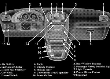
HAZARD WARNING FLASHER The hazard flasher switch is located in the center of the instrument panel above the radio.
Hazard Flasher Switch
To engage the Hazard Warning Flashers, depress the switch on the instrument panel. When the Hazard Warn- ing Switch is activated, all directional turn signals will flash on and off to warn oncoming traffic of an emer- gency. Push the switch a second time to turn off the flashers. This is an emergency warning system and should not be used when the vehicle is in motion. Use it when your vehicle is disabled and is creating a safety hazard for other motorists. When you must leave the vehicle to seek assistance, the Hazard Warning Flashers will continue to operate even though the ignition switch is OFF. NOTE: With extended use, the Hazard Warning Flash- ers may wear down your battery.
IF YOUR ENGINE OVERHEATS In any of the following situations, you can reduce the potential for overheating by taking the appropriate ac- tion. • On the highways — Slow down. • In city traffic — While stopped, put transmission in
neutral, but do not increase engine idle speed.
NOTE: There are steps that you can take to slow down an impending overheat condition. If your air conditioner is on, turn it off. The air conditioning system adds heat to the engine cooling system and turning off the A/C removes this heat. You can also turn the Temperature control to maximum heat, the Mode control to floor, and the fan control to High. This allows the heater core to act as a supplement to the radiator and aids in removing heat from the engine cooling system.
WHAT TO DO IN EMERGENCIES 347
CAUTION!
Driving with a hot cooling system could damage your vehicle. If temperature gauge reads “H”, pull over and stop the vehicle. Idle the vehicle with the air conditioner turned off until the pointer drops back into the normal range. If the pointer remains on the “H”, turn the engine off immediately, and call for service.
348 WHAT TO DO IN EMERGENCIES
WARNING!
JACKING AND TIRE CHANGING
A hot engine cooling system is dangerous. You or others could be badly burned by steam or boiling coolant. You may want to call a service center if your vehicle overheats. If you decide to look under the hood yourself, see Section 7, Maintenance, of this manual. Follow the warnings under the Cooling System Pressure Cap paragraph.
WARNING!
• Getting under a jacked-up vehicle is dangerous. The vehicle could slip off the jack and fall on you. You could be crushed. Never get any part of your body under a vehicle that is on a jack. If you need to get under a raised vehicle, take it to a service center where it can be raised on a lift. • The jack is designed to use as a tool for changing tires only. The jack should not be used to lift the vehicle for service purposes. The vehicle should be jacked on a firm level surface only. Avoid ice or slippery areas. • For vehicles equipped with fold-in-floor seating, if it is necessary to retrieve the spare tire from under the vehicle on the side of the vehicle close to moving traffic. Pull far enough off the road to avoid the danger of being hit.
Jacking Instructions — Fold-in-Floor Seating
Preparations For Jacking Park the vehicle on a firm level surface, avoid ice or slippery areas, set the parking brake and place the gear selector in PARK. Turn OFF the ignition.
WARNING!
Do not attempt to change a tire on the side of the vehicle close to moving traffic. Pull far enough off the road to avoid the danger of being hit when operating the jack or changing the wheel.
WHAT TO DO IN EMERGENCIES 349
• Turn on the Hazard Warning Flasher.
• Block both the front and rear of the wheel diagonally oppo- site the jacking position. For example, if changing the right front tire, block the left rear wheel. • Passengers should not remain in the vehicle when the
vehicle is being jacked.
350 WHAT TO DO IN EMERGENCIES
Jack Location — Fold-in-Floor Seating The jack, jack handle and winch handle tools are stowed behind the rear left side trim panel in the rear cargo area. Pull up on the lever to release the cover.
Remove the scissors jack and jack handle by rotating the small wing nut to the left. Also remove the tool pouch containing the spare tire winch handle tools, which is located next to the jack and jack handle.
Jack Location
Jack Removal/Installation
Spare Tire Stowage — Fold-in-Floor Seating For vehicles equipped with fold-in-floor seating, the spare tire is stowed inside a protective cover located under the center of the vehicle by means of a cable winch mechanism. The “spare tire drive” nut is located on the floor, under a plastic cap between the front seats. The tool pouch contains three pieces and can be as- sembled into a Spare Tire Hook to remove the compact spare tire/cover assembly from under the vehicle or a Winch “T” Handle to raise/lower the compact spare tire/cover assembly.
WHAT TO DO IN EMERGENCIES 351
352 WHAT TO DO IN EMERGENCIES
Jacking Instructions — Fold-in-Floor Seating 1. Loosen (but do not remove) the wheel lug nuts by turning them to the left one turn while the wheel is still on the ground. 2. To remove the compact spare tire/cover assembly, assemble the winch handle extensions to form a “T’ and fit the winch “T” handle over the drive nut. Rotate the nut to the left approximately 33 turns until the winch mechanism stops turning freely, this will allow enough slack in the cable to allow you to pull the spare tire out from under the vehicle.
Spare Tire Removal
CAUTION!
The winch mechanism is designed for use with the winch “T” handle only. Use of an air wrench or other power tools is not recommended and can damage the winch.
3. Assemble the winch handle extensions to form the Spare Tire Hook and pull the compact spare tire/cover assembly from under the vehicle.
WHAT TO DO IN EMERGENCIES 353
WARNING!
Getting under a jacked-up vehicle is dangerous. The vehicle could slip off the jack and fall on you. You could be crushed. Never get any part of your body under a vehicle that is on a jack. If you need to get under a raised vehicle, take it to a service center where it can be raised on a lift.
354 WHAT TO DO IN EMERGENCIES
If either front tire is flat, it may be necessary to NOTE: jack up the vehicle to remove the compact spare tire/ cover assembly from under the vehicle. Refer to jack engagement locations in the following steps for proper jack placement.
4. When the compact spare tire/cover assembly is clear of the vehicle, stand the tire/cover assembly upright and remove the wheel spacer by squeezing the two retaining tabs together.
Spare Tire/Cover Removal
Wheel Spacer Removal
5. There are two jack engagement locations on each side of the body, refer to the following illustration.
WHAT TO DO IN EMERGENCIES 355
Jack Engagement Locations
356 WHAT TO DO IN EMERGENCIES
6. These locations are on the sill flange of the body and consist of a pair of downstanding tabs. The jack is to be located, engaging the flange, between the pair of tabs closest to the wheel to be changed. Place the wrench on the jack screw and turn to the right until the jack head is properly engaged in the described location. Do not raise the vehicle until you are sure the jack is securely engaged. 7. Raise the vehicle by turning the jack screw to the right, using the swivel wrench. Raise the vehicle only until the tire just clears the surface and enough clearance is obtained to install the spare tire. Minimum tire lift provides maximum stability.
WARNING!
Raising the vehicle higher than necessary can make the vehicle less stable. It could slip off the jack and hurt someone near it. Raise the vehicle only enough to remove the tire.
8. Remove the wheel lug nuts, for vehicles with wheel covers, remove the cover from the wheel by hand. Do not pry the wheel cover off. Then pull the wheel off the hub. 9. Install the compact spare tire. Lightly tighten the lug nuts. To avoid the risk of forcing the vehicle off the jack, do not tighten the lug nuts fully until the vehicle has been lowered. NOTE: Do not install the wheel cover on the compact spare. Do not use a hammer or force to install the wheel covers.
10. Lower the vehicle by turning the jack screw to the left. 11. Finish tightening the lug nuts. Push down on the wrench while tightening for increased leverage. Alternate lug nuts until each nut has been tightened twice. Correct wheel nut tightness is 130 N·m (95 ft. lbs). If in doubt about the correct tightness, have them checked with a torque wrench by your dealer or at a service station. 12. Lower the jack to its fully closed position. 13. Secure the flat tire as follows: • Place the deflated (flat) tire and compact spare tire cover assembly in the rear cargo area, have the tire repaired or replaced as soon as possible.
WHAT TO DO IN EMERGENCIES 357
WARNING!
A loose deflated (flat) tire thrown forward in a collision or hard stop could injure the occupants in the vehicle. Have the deflated (flat) tire repaired or replaced immediately.
CAUTION!
Vehicle damage will occur if the compact spare tire cover assembly is installed without the compact spare tire in position. Place the deflated (flat) tire and compact spare tire cover assembly in the rear cargo area.
358 WHAT TO DO IN EMERGENCIES
14. Stow the cable and wheel spacer before driving the vehicle, reassemble the winch handle extensions to form a “T’ and fit the winch “T” handle over the drive nut. Rotate the nut to the right approximately 33 turns until the winch mechanism clicks at least three times. 15. Stow the jack, jack handle and winch handle tools.
Jack Removal/Installation
WARNING!
A loose jack, thrown forward in a collision or hard stop could endanger the occupants of the vehicle. Always stow the jack parts in the place provided.
16. Check the compact spare tire pressure as soon as possible. Correct pressure as required. Secure The Spare Tire As Follows: 1. To stow the compact spare tire/cover assembly on vehicles equipped with fold-in-floor seating, assemble the winch handle extensions to form a “T’ and fit the winch “T” handle over the drive nut. Rotate the nut to the left approximately 33 turns until the winch mecha- nism stops turning freely, this will allow enough slack in the cable to allow you to pull the wheel spacer out from under the vehicle.
WHAT TO DO IN EMERGENCIES 359
WARNING!
A loose compact spare tire/cover assembly, thrown forward in a collision or hard stop could endanger the occupants of the vehicle. Always stow the com- pact spare tire with the cover assembly in the place provided.
CAUTION!
The winch mechanism is designed for use with the winch “T” handle only. Use of an air wrench or other power tools is not recommended and can damage the winch.
2. Assemble the winch handle extensions to form the Spare Tire Hook and pull the wheel spacer from under the vehicle.
Spare Tire Removal
360 WHAT TO DO IN EMERGENCIES
3. Turn the compact spare tire so that the valve stem is down and place the tire into the spare tire cover assem- bly. Slide the wheel spacer through the center of the wheel and spare tire cover assembly so that the two retainer tabs snap out and engage the spare tire cover on the opposite side.
CAUTION!
The compact spare tire cover assembly must be used when the compact spare tire is stored. Failure to use this cover could drastically reduce the life of the compact spare tire.
WARNING!
Verify that ’both’ retainer tabs of the wheel spacer have been properly extended through the center of the wheel and spare tire cover assembly. Failure to properly engage both retainer tabs could result in loss of the spare tire & cover assembly, which will cause vehicle damage and may cause loss of control of the vehicle.
4. Using the winch “T” handle, rotate the drive nut to the right until the compact spare tire/cover assembly is drawn into place against the underside of the vehicle. 5. Continue to rotate the nut approximately 33 turns until you hear the winch mechanism click three times. It cannot be overtightened. Check under the vehicle to ensure the compact spare tire/cover assembly is posi- tioned correctly against the underside of the vehicle.
CAUTION!
For vehicles equipped with fold-in-floor seating, the Winch Mechanism is designed specifically to stow a COMPACT Spare Tire ONLY. Do not attempt to use the Winch to stow the Full Size ’Flat’ Tire, or any other Full Size Tire. Vehicle damage may result.
Jacking Instructions — Non Fold-in-Floor Seating
Preparations For Jacking Park the vehicle on a firm level surface, avoid ice or slippery areas, set the parking brake and place the gear selector in PARK. Turn OFF the ignition.
WHAT TO DO IN EMERGENCIES 361
WARNING!
Do not attempt to change a tire on the side of the vehicle close to moving traffic. Pull far enough off the road to avoid the danger of being hit when operating the jack or changing the wheel. • Turn on the Hazard Warning Flasher.
• Block both the front and rear of the wheel diagonally oppo- site the jacking position. For example, if changing the right front tire, block the left rear wheel. • Passengers should not remain in the vehicle when the
vehicle is being jacked.
362 WHAT TO DO IN EMERGENCIES
Jack Location — Non Fold-in-Floor Seating The jack, jack handle are stowed behind the rear left side trim panel in the rear cargo area. Pull up on the lever to release the cover. Remove the spare wheel, scissors jack and jack handle from stowage by rotating the wing nut to the left.
Spare Tire Stowage — Non Fold-in-Floor Seating For vehicles not equipped with fold-in-floor seating the spare tire is stowed under the rear of the vehicle by means of a cable winch mechanism. To remove or stow the spare, use the jack handle to rotate the “spare tire drive” nut. The nut is located under the plastic cover at the center rear of the cargo floor area, just inside the liftgate opening.
Jack Location
WHAT TO DO IN EMERGENCIES 363
2. Fit the jack handle over the drive nut. Rotate the nut to the left until the spare is on the ground with enough slack cable to allow you to pull the tire out from under the vehicle.
CAUTION!
The winch mechanism is designed for use with the jack handle only. Use of an air wrench or other power tools is not recommended and can damage the winch.
Lowering Spare Tire
Jacking Instructions — Non Fold-in-Floor Seating 1. Loosen (but do not remove) the wheel lug nuts by turning them to the left one turn while the wheel is still on the ground.
3. When the spare is clear, tilt the retainer at the end of the cable and pull it through the center of the wheel. 4. There are two jack engagement locations on each side of the body — refer to the following illustration.
364 WHAT TO DO IN EMERGENCIES
Jack Engagement Locations
5. These locations are on the sill flange of the body and consist of a pair of downstanding tabs. The jack is to be located, engaging the flange, between the pair of tabs closest to the wheel to be changed. Place the wrench on the jack screw and turn to the right until the jack head is properly engaged in the described location. Do not raise the vehicle until you are sure the jack is securely engaged. 6. Raise the vehicle by turning the jack screw to the right, using the swivel wrench. Raise the vehicle only until the tire just clears the surface and enough clearance is obtained to install the spare tire. Minimum tire lift provides maximum stability.
WHAT TO DO IN EMERGENCIES 365
WARNING!
Raising the vehicle higher than necessary can make the vehicle less stable. It could slip off the jack and hurt someone near it. Raise the vehicle only enough to remove the tire.
7. Remove the wheel lug nuts, for vehicles with wheel covers, remove the cover from the wheel by hand. Do not pry the wheel cover off. Then pull the wheel off the hub. 8. Install the spare wheel, for vehicles with wheel covers, align the notch in the wheel cover with the valve stem on the wheel. Install the cover on the wheel by hand only and install the wheel lug nuts with the cone shaped end of the nut toward the wheel. Lightly tighten the lug nuts. To avoid the risk of forcing the vehicle off the jack, do not tighten the lug nuts fully until the vehicle has been lowered.
366 WHAT TO DO IN EMERGENCIES
NOTE: Do not install the wheel cover on the compact spare. Do not use a hammer or force to install the wheel covers. 9. Lower the vehicle by turning the jack screw to the left. 10. Finish tightening the lug nuts. Push down on the wrench while tightening for increased leverage. Alternate lug nuts until each nut has been tightened twice. Correct wheel nut tightness is 130 N·m (95 ft. lbs). If in doubt about the correct tightness, have them checked with a torque wrench by your dealer or at a service station. 11. Lower the jack to its fully closed position.
WARNING!
A loose tire or jack, thrown forward in a collision or hard stop could endanger the occupants of the ve- hicle. Always stow the jack parts and the spare tire in the places provided.
12. Secure the flat or spare tire as follows: • If your vehicle is equipped with cast aluminum wheels, the center cap of the wheel must be re- moved prior to flat tire stowage. Store the center cap inside the glove box or other storage compartment. • Turn the wheel so that the valve stem is down. Slide the wheel retainer through the center of the wheel and position it properly across the wheel opening.
• For convenience in checking the spare tire inflation, stow with the valve stem toward the rear of the vehicle. • Using the jack handle, rotate the drive nut to the right until the wheel is drawn into place against the underside of the vehicle. • Continue to rotate the nut until you hear the mecha- nism click three times. It cannot be overtightened. Push against the tire several times to be sure it is securely in place.
13. Stow the jack and jack handle. 14. Check the tire pressure as soon as possible. Correct pressure as required.
WHAT TO DO IN EMERGENCIES 367
JUMP-STARTING PROCEDURES IF BATTERY IS LOW
WARNING!
Take care to avoid the radiator cooling fan whenever the hood is raised. It can start anytime the ignition switch is on. You can be hurt by the fan.
368 WHAT TO DO IN EMERGENCIES
WARNING!
• Do not attempt to push or tow your vehicle to get it
started. Vehicles equipped with an automatic transmis- sion cannot be started this way. Unburned fuel could enter the catalytic converter and once the engine has started, ignite and damage the converter and vehicle. If the vehicle has a discharged battery, booster cables may be used to obtain a start from another vehicle. This type of start can be dangerous if done improperly, so follow this procedure carefully.
• Battery fluid is a corrosive acid solution; do not allow
battery fluid to contact eyes, skin or clothing. Don’t lean over battery when attaching clamps or allow the clamps to touch each other. If acid splashes in eyes or on skin, flush contaminated area immediately with large quan- tities of water.
• A battery generates hydrogen gas which is flammable
and explosive. Keep flame or spark away from the vent holes. Do not use a booster battery or any other booster source with an output that exceeds 12 volts.
1. Wear eye protection and remove any metal jewelry such as watch bands or bracelets that might make an inadvertent electrical contact. 2. When boost is provided by a battery in another vehicle, park that vehicle within booster cable reach and without letting the vehicles touch. Set the parking brake, place the automatic transmission in PARK and turn the ignition switch to the OFF position for both vehicles. 3. Turn off the heater, radio and all unnecessary electrical loads. 4. Connect one end of a jumper cable to the positive terminal of the discharged battery. Connect the other end of the same cable to the positive terminal of the booster battery.
5. Connect the other cable, first to the negative terminal of the booster battery and then to the engine of the vehicle with the discharged battery. Make sure you have a good contact on the engine. 6. Start the engine in the vehicle which has the booster battery, let the engine idle a few minutes, then start the engine in the vehicle with the discharged battery. 7. When removing the jumper cables, reverse the above sequence exactly. Be careful of the moving belts and fan.
DRIVING ON SLIPPERY SURFACES
Acceleration Rapid acceleration on snow covered, wet, or other slip- pery surfaces may cause the front wheels to pull errati- cally to the right or left. This phenomenon occurs when there is a difference in the surface traction under the front (driving) wheels.
WHAT TO DO IN EMERGENCIES 369
WARNING!
Rapid acceleration on slippery surfaces is danger- ous. Unequal traction can cause sudden pulling of the front wheels. You could lose control of the vehicle and possibly have an accident. Accelerate slowly and carefully whenever there is likely to be poor traction (ice, snow, wet mud, loose sand, etc.).
Traction When driving on wet or slushy roads, it is possible for a wedge of water to build up between the tire and road surface. This is known as hydroplaning and may cause partial or complete loss of vehicle control and stopping ability. To reduce this possibility, the following precau- tions should be observed: 1. Slow down during rainstorms or when roads are slushy.
370 WHAT TO DO IN EMERGENCIES
2. Slow down if road has standing water or puddles. 3. Replace tires when tread wear indicators first become visible. 4. Keep tires properly inflated. 5. Maintain sufficient distance between your vehicle and the vehicle in front to avoid a collision in a sudden stop.
FREEING A STUCK VEHICLE If your vehicle becomes stuck in mud, sand or snow, it can often be moved by a rocking motion. Turn your steering wheel right and left to clear the area around the front wheels. Then shift back and forth between Reverse and Drive. Usually the least accelerator pedal pressure to maintain the rocking motion without spinning the wheels is most effective.
WARNING!
Fast spinning tires can be dangerous. Forces gener- ated by excessive wheel speeds may cause tire dam- age or failure. A tire could explode and injure someone. Do not spin your vehicle’s wheels faster than 35 mph (55 km/h) when you are stuck. And don’t let anyone near a spinning wheel, no matter what the speed.
CAUTION!
Racing the engine or spinning the wheels too fast may lead to transmission overheating and failure. It can also damage the tires. Do not spin the wheels above 35 mph (55 km/h).
TOWING A DISABLED VEHICLE
With Ignition Key Your vehicle may be towed under the following condi- tions: The gear selector must be in NEUTRAL, the distance to be traveled must not exceed 100 miles (160
km), and the towing speed must not exceed 44 mph (72
km/h). Exceeding these towing limits may cause a trans- mission geartrain failure. If the transmission is not op- erative, or if the vehicle is to be towed more than 100
miles (160 km), the vehicle must be towed with the front wheels off the ground.WHAT TO DO IN EMERGENCIES 371
CAUTION!
• Do not attempt to tow this vehicle from the front with sling type towing equipment. Damage to the front fascia will result. • Always use wheel lift equipment when towing from the front. The only other approved method of towing is with a flat bed truck. • Do not tow the vehicle from the rear. Damage to the rear sheet metal, liftgate and fascia will occur. • Do not push or tow this vehicle with another vehicle as damage to the bumper fascia and trans- mission may result. • If the vehicle being towed requires steering, the ignition switch must be in the OFF position, not in the LOCK or ACCESSORY positions.
372 WHAT TO DO IN EMERGENCIES
If it is necessary to use the accessories while being towed (wipers, defrosters, etc.), the key must be in the ON position, not the ACCESSORY position. Make certain the transmission remains in NEUTRAL. Without The Ignition Key Special care must be taken when the vehicle is towed with the ignition in the LOCK position. The only ap- proved method of towing with out the ignition key is with a flat bed truck. Proper towing equipment is neces- sary to prevent damage to the vehicle.
TOWING THIS VEHICLE BEHIND ANOTHER VEHICLE (Flat towing with all four wheels on the ground) Flat towing of vehicles equipped with an automatic transmission, is only permitted within the limitations described in this section. TOWING THIS VEHICLE BEHIND ANOTHER VEHICLE WITH A TOW DOLLEY The manufacture does not recommend that you tow a front wheel drive vehicle on a tow dolley. Vehicle damage may occur.
MAINTAINING YOUR VEHICLE
CONTENTS
䡵 3.3L/3.8L Engines . . . . . . . . . . . . . . . . . . . . . . 376
䡵 Onboard Diagnostic System — OBD II . . . . . . . . 377
䡵 Emissions Inspection And MaintenancePrograms
. . . . . . . . . . . . . . . . . . . . . . . . . . . . 378
䡵 Replacement Parts . . . . . . . . . . . . . . . . . . . . . . 379
䡵 Dealer Service . . . . . . . . . . . . . . . . . . . . . . . . . 379
䡵 Maintenance Procedures . . . . . . . . . . . . . . . . . . 380
▫ Engine Oil . . . . . . . . . . . . . . . . . . . . . . . . . . 380
▫ Engine Oil Filter . . . . . . . . . . . . . . . . . . . . . . 384▫ Drive Belts — Check Condition
And Tension . . . . . . . . . . . . . . . . . . . . . . . . . 384
▫ Spark Plugs . . . . . . . . . . . . . . . . . . . . . . . . . 385
▫ Engine Air Cleaner Filter . . . . . . . . . . . . . . . . 385
▫ Catalytic Converter . . . . . . . . . . . . . . . . . . . . 385
▫ Maintenance-Free Battery . . . . . . . . . . . . . . . . 387
▫ Air Conditioner Maintenance . . . . . . . . . . . . . 389
▫ Power Steering — Fluid Check . . . . . . . . . . . . 390
▫ Front Suspension Ball Joints . . . . . . . . . . . . . . 391374 MAINTAINING YOUR VEHICLE
▫ Steering Shaft Seal . . . . . . . . . . . . . . . . . . . . 391
▫ Steering Linkage . . . . . . . . . . . . . . . . . . . . . . 391
▫ Drive Shaft Universal Joints . . . . . . . . . . . . . . 391
▫ Body Lubrication . . . . . . . . . . . . . . . . . . . . . 392
▫ Windshield Wiper Blades . . . . . . . . . . . . . . . . 392
▫ Windshield And Rear Window Washers . . . . . 393
▫ Exhaust System . . . . . . . . . . . . . . . . . . . . . . 393
▫ Cooling System . . . . . . . . . . . . . . . . . . . . . . . 394
▫ Hoses And Vacuum/Vapor Harnesses . . . . . . . 399
▫ Brakes . . . . . . . . . . . . . . . . . . . . . . . . . . . . . 400
▫ Master Cylinder — ABS Brakes Brake FluidLevel Check . . . . . . . . . . . . . . . . . . . . . . . . . 401
▫ Fuel System Hoses . . . . . . . . . . . . . . . . . . . . 403▫ Automatic Transmission . . . . . . . . . . . . . . . . 403
▫ Front And Rear Wheel Bearings . . . . . . . . . . . 406
▫ Appearance Care And ProtectionFrom Corrosion . . . . . . . . . . . . . . . . . . . . . . 406
▫ Cleaning The Instrument Panel And Underseat
Cup Holders
. . . . . . . . . . . . . . . . . . . . . . . . 411
䡵 Integrated Power Module (IPM) . . . . . . . . . . . . 412
䡵 Vehicle Storage . . . . . . . . . . . . . . . . . . . . . . . . 415
䡵 Replacement Light Bulbs . . . . . . . . . . . . . . . . . 416
䡵 Bulb Replacement . . . . . . . . . . . . . . . . . . . . . . 417
▫ Headlights . . . . . . . . . . . . . . . . . . . . . . . . . . 417
▫ Front Park/Turn Signal AndSidemarker Lights . . . . . . . . . . . . . . . . . . . . . 418
. . . . . . . . . . . . . . . . . . . . . . 419▫ Front Fog Light
▫ Rear Tail, Stop, Turn Signal, Side Marker And
Back-Up Lights . . . . . . . . . . . . . . . . . . . . . . . 420
▫ Center High Mounted Stop Light (CHMSL) . . . 421
▫ License Light . . . . . . . . . . . . . . . . . . . . . . . . 421
. . . . . . . . . . . . . . . . . . . 422䡵 Fluids And Capacities
MAINTAINING YOUR VEHICLE 375
䡵 Recommended Fluids, Lubricants And
Genuine Parts . . . . . . . . . . . . . . . . . . . . . . . . . 423
▫ Engine . . . . . . . . . . . . . . . . . . . . . . . . . . . . . 423
▫ Chassis . . . . . . . . . . . . . . . . . . . . . . . . . . . . 424376 MAINTAINING YOUR VEHICLE
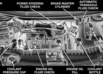
3.3L/3.8L ENGINES
Engine Compartment 3.3L/3.8L Engines
ONBOARD DIAGNOSTIC SYSTEM — OBD II Your vehicle is equipped with a sophisticated onboard diagnostic system called OBD II. This system monitors the performance of the emissions, engine, and automatic transmission control systems. When these systems are operating properly, your vehicle will provide excellent performance and fuel economy, as well as engine emis- sions well within current government regulations. If any of these systems require service, the OBD II system will turn on the “Malfunction Indicator Light.” It will also store diagnostic codes and other information to assist your service technician in making repairs. Al- though your vehicle will usually be drivable and not need towing, see your dealer for service as soon as possible.
MAINTAINING YOUR VEHICLE 377
CAUTION!
• Prolonged driving with the “Malfunction Indica- tor Light” on could cause further damage to the emission control system. It could also affect fuel economy and driveability. The vehicle must be serviced before any emissions tests can be per- formed. • If the “Malfunction Indicator Light” is flashing while the engine is running, severe catalytic con- verter damage and power loss will soon occur. Immediate service is required.
378 MAINTAINING YOUR VEHICLE
EMISSIONS INSPECTION AND MAINTENANCE PROGRAMS In some localities, it may be a legal requirement to pass an inspection of your vehicle’s emissions control system. Failure to pass could prevent vehicle registration.
For states which have an I/M (Inspection and Maintenance) requirement, this check verifies the following: the MIL (Malfunction Indicator Lamp) is functioning and is not on when the engine is running, and that the OBD (On Board Diagnostic) system is ready for testing. Normally, the OBD system will be ready. The OBD system may not be ready if your vehicle was recently serviced, if you recently had a dead battery, or a battery replacement. If the OBD system should be determined not ready for the I/M test, your vehicle may fail the test.
Your vehicle has a simple ignition key actuated test which you can use prior to going to the test station. To check if your vehicle’s OBD system is ready, you must do the following: 1. Insert your ignition key into the ignition switch. 2. Turn the ignition to the ON position, but do not crank or start the engine. 3. If you crank or start the engine, you will have to start this test over. 4. As soon as you turn your key to the ON position, you will see your MIL symbol come on as part of a normal bulb check. 5. Approximately 15 seconds later, one of two things will happen:
a. The MIL will flash for about 10 seconds and then return to being fully illuminated until you turn off the
ignition key or start the engine. This means that your vehicle’s OBD system is not ready and you should not proceed to the I/M station. b. The MIL will not flash at all and will remain fully illuminated until you turn off the ignition key or start the engine. This means that your vehicle’s OBD system is ready and you can proceed to the I/M station.
If your OBD system is not ready, you should see your authorized dealer or repair facility. If your vehicle was recently serviced or had a battery failure or replacement, you may need to do nothing more than drive your vehicle as you normally would in order for your OBD system to update. A recheck with the above test routine may then indicate that the system is now ready. Regardless of whether your vehicle’s OBD system is ready or not ready, if the MIL symbol is illuminated during normal vehicle operation, you should have your
MAINTAINING YOUR VEHICLE 379
vehicle serviced before going to the I/M station. The I/M station can fail your vehicle because the MIL symbol is on with the engine running.
REPLACEMENT PARTS Use of genuine Mopar威 parts for normal/scheduled maintenance and repairs is highly recommended to in- sure the designed performance. Damage or failures caused by the use of non-Mopar威 parts for maintenance and repairs will not be covered by the manufacturer’s warranty.
DEALER SERVICE Your dealer has the qualified service personnel, special tools and equipment to perform all service operations in an expert manner. Service Manuals are available which include detailed service information for your vehicle. Refer to these manuals before attempting any procedure yourself.
380 MAINTAINING YOUR VEHICLE
NOTE: systems can result against you.
Intentional tampering with emissions control in civil penalties being assessed
WARNING!
You can be badly injured working on or around a motor vehicle. Do only that service work for which you have the knowledge and the proper equipment. If you have any doubt about your ability to perform a service job, take your vehicle to a competent mechanic.
MAINTENANCE PROCEDURES The pages that follow contain the required maintenance services determined by the engineers who designed your vehicle. Besides the maintenance items for which there are fixed maintenance intervals, there are other items that should operate satisfactorily without periodic maintenance. However, if a malfunction of these items does occur, it could adversely affect the engine or vehicle performance. These items should be inspected if a malfunction is observed or suspected. Engine Oil
Checking Oil Level To assure proper engine lubrication, the engine oil must be maintained at the correct level. Check the oil level at regular intervals, such as every fuel stop.
MAINTAINING YOUR VEHICLE 381
The best time to check the engine oil level is about 5
minutes after a fully warmed engine is shut off or before starting the engine after it has sat overnight. Checking the oil while the vehicle is on level ground will improve the accuracy of the oil level readings. Maintain the oil level between the MIN and MAX markings on the dipstick. Adding one quart of oil when the reading is at the MIN mark will result in a MAX reading on these engines.Engine Oil Dipstick
CAUTION!
Overfilling or underfilling will cause oil aeration or loss of oil pressure. This could damage your engine.
382 MAINTAINING YOUR VEHICLE
Change Engine Oil Road conditions and your kind of driving affects the interval at which your oil should be changed. Check the following list to see if any apply to you. • Day or night temperatures are below 32°F (0°C). • Stop and Go driving. • Extensive engine idling. • Driving in dusty conditions. • Short trips of less than 10 miles (16 km). • More than 50% of your driving is at sustained high • Trailer towing. • Taxi, Police or delivery service (commercial service). • Off-Road or desert operation.
speeds during hot weather, above 90°F (32°C).
If ANY of these apply to you, then change your engine oil every 3,000 miles (4 800 km) or 3 months, whichever comes first. If none of these apply to you, then change your engine oil every 6,000 miles (10 000 km) or 6 months whichever comes first. NOTE: Under no circumstances should oil change in- tervals exceed 6,000 miles (10 000 km) or 6 months whichever comes first. Engine Oil Selection For best performance and maximum protection under all types of operating conditions, the manufacturer only recommends engine oils that are API certified and meet the requirements of DaimlerChrysler Material Standard MS-6395.
American Petroleum Institute (API) Engine Oil Identification Symbol
This symbol means that the oil has been certified by the American Petroleum Institute (API). The manufacturer only recommends API Certified engine oils.
Engine Oil Viscosity (SAE Grade) SAE 5W-20 engine oil is recommended for all operating temperatures. This engine oil improves low temperature starting and vehicle fuel economy. Refer to your engine oil filler cap for the recommended engine oil viscosity for your vehicle. For information on engine oil filler cap location, refer to the Engine Compartment illustration in this section.
MAINTAINING YOUR VEHICLE 383
Lubricants which do not have both, the engine oil certi- fication mark and the correct SAE viscosity grade num- ber should not be used. Synthetic Engine Oils There are a number of engine oils being promoted as either synthetic or semi-synthetic. If you chose to use such a product, use only those oils that meet the Ameri- can Petroleum Institute (API) and have the correct SAE viscosity grade. Follow the maintenance schedule that describes your driving type. Materials Added to Engine Oil The manufacture strongly recommends against the addi- tion of any additives (other than leak detection dyes) to the engine oil. Engine oil is an engineered product and it’s performance may be impaired by supplemental ad- ditives.
384 MAINTAINING YOUR VEHICLE
Disposing of Used Engine Oil And Oil Filters Care should be taken in disposing of used engine oil and oil filters from your vehicle. Used oil and oil filters, indiscriminately discarded, can present a problem to the environment. Contact your dealer, service station, or governmental agency for advice on how and where used oil and oil filters can be safely discarded in your area. Engine Oil Filter The engine oil filter should be replaced at every engine oil change. Engine Oil Filter Selection The manufacturer’s engines have a full-flow type oil filter. Use a filter of this type for replacement. The quality of replacement filters varies considerably. Only high quality filters should be used to assure most efficient service. Mopar Engine Oil Filters are a high quality oil filter and are recommended.
Drive Belts — Check Condition and Tension At the mileage indicated in the maintenance schedule, all belts should be checked for condition and proper tension. Improper belt tension can cause belt slippage and failure. Belts should be inspected for evidence of cuts, cracks, or glazing, and replaced if there is indication of damage which could result in belt failure. If adjustment is re- quired, see your authorized dealer for service. Low generator belt tension can cause battery failure. A special tool is required to properly measure tension and to restore belt tension to factory specifications. Also check belt routing to make sure there is no interfer- ence between the belts and other engine components.
Spark Plugs Spark plugs must fire properly to assure engine perfor- mance and emission control. New plugs should be in- stalled at the specified mileage. The entire set should be replaced if there is any malfunction due to a faulty spark plug, malfunctioning spark plugs can damage the cata- lytic converter. For proper type of replacement spark plugs, refer to the “Vehicle Emission Control Informa- tion” label in the engine compartment. Engine Air Cleaner Filter Under normal driving conditions, replace the air filter at the intervals shown on Schedule “A”. If, however, you drive the vehicle frequently under dusty or severe con- ditions, the filter element should be inspected periodi- cally and replaced if necessary at the intervals shown on Schedule “B”.
MAINTAINING YOUR VEHICLE 385
WARNING!
The air cleaner can provide a measure of protection in the case of engine backfire. Do not remove the air cleaner unless such removal is necessary for repair or maintenance. Make sure that no one is near the engine compartment before starting the vehicle with the air cleaner removed. Failure to do so can result in serious personal injury.
Catalytic Converter The catalytic converter requires the use of unleaded fuel only. Leaded gasoline will destroy the effectiveness of the catalyst as an emission control device.
386 MAINTAINING YOUR VEHICLE
Under normal operating conditions, the catalytic con- verter will not require maintenance. However, it is im- portant to keep the engine properly tuned to assure proper catalyst operation and prevent possible catalyst damage.
CAUTION!
Damage to the catalytic converter can result if your vehicle is not kept in proper operating condition. In the event of engine malfunction, particularly involv- ing engine misfire or other apparent loss of perfor- mance, have your vehicle serviced promptly. Contin- ued operation of your vehicle with a severe malfunction could cause the converter to overheat, resulting in possible damage to the converter and the vehicle.
NOTE: systems can result against you.
Intentional tampering with emissions control in civil penalties being assessed
WARNING!
A hot exhaust system can start a fire if you park over materials that can burn. Such materials might be grass or leaves coming into contact with your ex- haust system. Do not park or operate your vehicle in areas where your exhaust system can contact any- thing that can burn.
In unusual situations involving grossly malfunctioning engine operation, a scorching odor may indicate severe and abnormal catalyst overheating. If this occurs, the vehicle should be stopped, the engine shut off and the
vehicle allowed to cool. Thereafter, service, including a tune-up to manufacturer’s specifications, should be ob- tained immediately. To minimize the possibility of catalyst damage: • Do not shut off the engine or interrupt the ignition when the transmission is in gear and the vehicle is in motion. • Do not try to start engine by pushing or towing the • Do not idle the engine with any spark plug wires disconnected or removed, such as when diagnostic testing, or for prolonged periods during very rough idling or malfunctioning operating conditions.
vehicle.
MAINTAINING YOUR VEHICLE 387
Maintenance-Free Battery The top of the MAINTENANCE-FREE battery is perma- nently sealed. You will never have to add water, nor is periodic maintenance required.
388 MAINTAINING YOUR VEHICLE
WARNING!
Battery fluid is a corrosive acid solution and can burn or even blind you. Don’t allow battery fluid to contact your eyes, skin or clothing. Don’t lean over a battery when attaching clamps. If acid splashes in eyes or on skin, flush the area immediately with large amounts of water. Battery gas is flammable and explosive. Keep flame or sparks away from the battery. Don’t use a booster battery or any other booster source with an output greater than 12 volts. Don’t allow cable clamps to touch each other. Battery posts, terminals and related accessories con- tain lead and lead compounds. Wash hands after handling.
CAUTION!
It is essential when replacing the cables on the battery that the positive cable is attached to the positive post and the negative cable is attached to the negative post. Battery posts are marked positive (+) and negative (-) and identified on the battery case. Cable clamps should be tight on the terminal posts and free of corrosion. If a “fast charger” is used while battery is in vehicle, disconnect both vehicle battery cables before con- necting the charger to battery. Do not use a “fast charger” to provide starting voltage.
Air Conditioner Maintenance For best possible performance, your air conditioner should be checked and serviced by an Authorized Dealer at the start of each warm season. This service should include cleaning of the condenser fins and a system performance check. Drive belt tension should also be checked at this time.
MAINTAINING YOUR VEHICLE 389
WARNING!
• Use only refrigerants and compressor lubricants approved by the manufacturer for your air condi- tioning system. Some unapproved refrigerants are flammable and can explode, injuring you. Other unapproved refrigerants or lubricants can cause the system to fail, requiring costly repairs. Refer to Section 3 of the Warranty Information book for further warranty information. • The air conditioning system contains refrigerant under high pressure. To avoid risk of personal injury or damage to the system, adding refrigerant or any repair requiring lines to be disconnected should be done by an experienced repairman.
390 MAINTAINING YOUR VEHICLE
Refrigerant Recovery And Recycling R-134a Air Conditioning Refrigerant is a hydrofluorocar- bon (HFC) that is endorsed by the Environmental Pro- tection Agency and is an ozone-saving product. How- ever, the manufacturer recommends that air conditioning service be performed by dealers or other service facilities using recovery and recycling equipment. NOTE: Use only manufacturer approved A/C System Sealers, Stop Leak Products, Seal Conditioners, Compres- sor Oil, or Refrigerants. A/C Air Filter The filter access door is located under the instrument panel on the passenger side. To replace the filter slide the lock toward the rear of the vehicle (unlock position). Remove the access door and pull the filter downward. When installing a new filter, ensure its proper orienta- tion. Align the black arrow on the bottom of the filter
frame with the direction of airflow (away from the blower motor and towards the center of the car). Refer to the “Maintenance Schedules” section of this manual for the recommended air conditioning filter replacement intervals. Power Steering — Fluid Check Checking the power steering fluid level at a defined service interval is not required. The fluid should only be checked if a leak is suspected, abnormal noises are apparent, and/or the system is not functioning as antici- pated. Coordinate inspection efforts through a certified DaimlerChrysler Dealership.⬙
WARNING!
Fluid level should be checked on a level surface and with the engine off to prevent injury from moving parts and to insure accurate fluid level reading. Do not overfill. Use only manufacturers recommended power steering fluid.
If necessary, add fluid to restore to the proper indicated level. With a clean cloth, wipe any spilled fluid from all surfaces. Refer to Recommended Fluids, Lubricants, and Genuine Parts for correct fluid type. Front Suspension Ball Joints The front suspension ball joints are permanently sealed. No regular maintenance is required for these compo- nents.
MAINTAINING YOUR VEHICLE 391
Steering Shaft Seal The steering shaft seal, at the point where the shaft passes through the bulkhead, is lubricated when it is installed. If the seal becomes noisy when the steering shaft is turned, it should be lubricated with a multi-purpose grease. Mopar multi-purpose lubricant is recommended. Steering Linkage The tie rod end ball joints are permanently lubricated and do not require periodic maintenance. Drive Shaft Universal Joints Your vehicle has constant velocity universal joints. Peri- odic lubrication of these joints is not required. However, the joint boots should be inspected for external leakage or damage when other maintenance is performed. If leakage or damage is evident, the universal joint boot and grease should be replaced immediately.
392 MAINTAINING YOUR VEHICLE
Continued operation could result in failure of the univer- sal joint due to water and dirt contamination of the grease. This would require complete replacement of the joint assembly. Body Lubrication Locks and all body pivot points, including such items as seat tracks, doors, liftgate, sliding doors and hood hinges, should be lubricated periodically to assure quiet, easy operation and to protect against rust and wear. Prior to the application of any lubricant, the parts concerned should be wiped clean to remove dust and grit; after lubricating excess oil and grease should be removed. Particular attention should also be given to hood latching components to insure proper function. When performing other underhood services, the hood latch, release mecha- nism and safety catch should be cleaned and lubricated. The external lock cylinders should be lubricated twice a year, preferably in the fall and spring. Apply a small
amount of a high quality lubricant such as Mopar威 Lock Cylinder Lubricant directly into the lock cylinder. Windshield Wiper Blades The rubber edges of the wiper blades and the windshield should be cleaned periodically with a sponge or soft cloth and a mild nonabrasive cleaner. This will remove accu- mulations of salt or road film. Operation of the wipers on dry glass for long periods may cause deterioration of the wiper blades. Always use washer fluid when using the wipers to remove salt or dirt from a dry windshield. Avoid using the wiper blades to remove frost or ice from the windshield. Keep the blade rubber out of contact with petroleum products such as engine oil, gasoline, etc.
MAINTAINING YOUR VEHICLE 393
Windshield and Rear Window Washers The fluid reservoir for the windshield washers and the rear window washer is shared. It is located in the engine compartment and should be checked for fluid level at regular intervals. Fill the reservoir with windshield washer solvent (not radiator antifreeze) and operate the system for a few seconds to flush out the residual water. The washer fluid reservoir will hold a full gallon of fluid when the Low Washer Fluid Light illuminates.
Washer Fluid Reservoir
Exhaust System The best protection against carbon monoxide entry into the vehicle body is a properly maintained engine exhaust system. Whenever a change is noticed in the sound of the exhaust system, when exhaust fumes can be detected inside the
394 MAINTAINING YOUR VEHICLE
vehicle, or when the underside or rear of the vehicle is damaged, have a competent mechanic inspect the com- plete exhaust system and adjacent body areas for broken, damaged, deteriorated, or mispositioned parts. Open seams or loose connections could permit exhaust fumes to seep into the passenger compartment. In addition, inspect the exhaust system each time the vehicle is raised for lubrication or oil change. Replace as required.
WARNING!
Exhaust gases can injure or kill. They contain carbon monoxide (CO) which is colorless and odorless. Breathing it can make you unconscious and can eventually poison you. To avoid breathing CO, fol- low the preceding safety tips.
Cooling System
Inspection
WARNING!
• When working near the radiator cooling fan, turn the ignition key to the OFF position. The fan is temperature controlled and can start at any time when the ignition key is in the ON position. • You or others can be badly burned by hot coolant or steam from your radiator. If you see or hear steam coming from under the hood, don’t open the hood until the radiator has had time to cool. Never try to open a cooling system pressure cap when the radiator is hot.
Coolant Checks Check engine coolant (antifreeze) protection every 12
months (before the onset of freezing weather, where applicable). If coolant is dirty or rusty in appearance, the system should be drained, flushed and refilled with fresh coolant. Check the front of the A/C condenser for any accumulation of bugs, leaves, etc. If dirty, clean by gently spraying water from a garden hose vertically down the face of the condenser. Check the coolant recovery bottle tubing for brittle rub- ber, cracking, tears, cuts and tightness of the connection at the bottle and radiator. Inspect the entire system for leaks. With the engine at normal operating temperature (but not running), check the coolant pressure cap for proper vacuum sealing by draining a small amount of coolant from the radiator drain cock. If the cap is sealing prop- erly, the coolant will begin to drain from the coolantMAINTAINING YOUR VEHICLE 395
recovery bottle. DO NOT REMOVE THE COOLANT PRESSURE CAP WHEN THE COOLING SYSTEM IS HOT. Cooling System — Drain, Flush and Refill At the intervals shown in the maintenance schedules, the system should be drained, flushed and refilled. If the solution is dirty or contains a considerable amount of sediment, clean and flush with a reliable cooling system cleaner. Follow with a thorough rinsing to remove all deposits and chemicals. Properly dispose of old antifreeze solution. Selection Of Coolant Use only the manufacturers recommended coolant, refer to Recommended Fluids, Lubricants and Genuine Parts for correct coolant type.
396 MAINTAINING YOUR VEHICLE
CAUTION!
• Mixing of coolants other than specified engine coolant, may result in engine damage, and de- crease corrosion protection. If a non-HOAT cool- ant is introduced into the cooling system in an emergency, it should be replaced with the speci- fied coolant as soon as possible. • Do not use plain water alone or alcohol base engine coolant (antifreeze) products. Do not use additional rust inhibitors or antirust products, as they may not be compatible with the radiator engine coolant and may plug the radiator. • This vehicle has not been designed for use with Propylene Glycol based coolants. Use of Propy- lene Glycol based coolants is not recommended.
Adding Coolant When adding coolant, or refilling the system, a minimum solution of 50% recommended HOAT ethylene glycol engine coolant (antifreeze) and distilled water should be used. Use higher concentrations (not to exceed 70%) if temperatures below ⫺34°F (⫺37°C) are anticipated. Use only high purity water such as distilled or deionized water when mixing the water/engine coolant solution. The use of lower quality water will reduce the amount of corrosion protection in the engine cooling system. Please note that it is the owner’s responsibility to main- tain the proper level of protection against freezing ac- cording to the temperatures occurring in the area where the vehicle is operated. NOTE: Mixing coolant types will decrease the life of the engine coolant and will require more frequent coolant changes.
Cooling System Pressure Cap The cap must be fully tightened to prevent loss of coolant, and to insure that coolant will return to the radiator from the coolant recovery bottle. The cap should be inspected and cleaned if there is any accumulation of foreign material on the sealing surfaces.
MAINTAINING YOUR VEHICLE 397
WARNING!
• The warning words “DO NOT OPEN HOT” on the cooling system pressure cap are a safety pre- caution. Never add coolant when the engine is overheated. Do not loosen or remove the cap to cool an overheated engine. Heat causes pressure to build up in the cooling system. To prevent scalding or injury, do not remove the pressure cap while the system is hot or under pressure. • Do not use a pressure cap other than the one specified for your vehicle. Personal injury or engine damage may result.
Disposal of Used Engine Coolant Used ethylene glycol based engine coolant is a regulated substance requiring proper disposal. Check with your local authorities to determine the disposal rules for your community. To prevent ingestion by animals or children
398 MAINTAINING YOUR VEHICLE
do not store ethylene glycol based engine coolant in open containers or allow it to remain in puddles on the ground. If ingested by a child, contact a physician immediately. Clean up any ground spills immediately. Coolant Level The coolant recovery bottle provides a quick visual method for determining that the coolant level is ad- equate. With the engine cold, the level of the coolant in the coolant recovery bottle should be between the “MAX” and “MIN” marks. The radiator normally re- mains completely full, so there is no need to remove the radiator cap except for checking coolant freeze point or replacement with new antifreeze coolant. Your service attendant should be advised of this. So long as the engine operating temperature is satisfactory, the coolant recov- ery bottle need only be checked once a month.
When additional coolant is needed to maintain the proper level, it should be added to the coolant recovery bottle. Do not overfill. Points to Remember NOTE: When the vehicle is stopped after a few miles of operation, you may observe vapor coming from the front of the engine compartment. This is normally a result of moisture from rain, snow, or high humidity accumulat- ing on the radiator and being vaporized when the thermostat opens, allowing hot water to enter the radia- tor. If an examination of your engine compartment shows no evidence of radiator or hose leaks, the vehicle may be safely driven. The vapor will soon dissipate. • Do not overfill the coolant recovery bottle.
• Check coolant freeze point in the radiator and in the coolant recovery bottle. If antifreeze needs to be added, contents of coolant recovery bottle must also be protected against freezing. • If frequent coolant additions are required, or if the level in the coolant recovery bottle does not drop when the engine cools, the cooling system should be pres- sure tested for leaks. • Maintain coolant concentration at 50% HOAT ethylene glycol engine coolant (minimum) and distilled water for proper corrosion protection of your engine which contains aluminum components. • Make sure that the radiator and coolant recovery bottle overflow hoses are not kinked or obstructed. • Keep the front of the radiator clean. If your vehicle is equipped with air conditioning, keep the front of the condenser clean, also.
MAINTAINING YOUR VEHICLE 399
• Do not change the thermostat for summer or winter operation. If replacement is ever necessary, install ONLY the correct type thermostat. Other designs may result in unsatisfactory cooling performance. • Increasing engine speed at idle does not reduce cool- ant temperature! Put transmission in NEUTRAL and let engine idle at normal engine idle speed.
Hoses And Vacuum/Vapor Harnesses Inspect surfaces of hoses and nylon tubing for evidence of heat and mechanical damage. Hard or soft spots, brittle rubber, cracking, tears, cuts, abrasions, and exces- sive swelling indicate deterioration of the rubber. Pay particular attention to those hoses nearest to high heat sources such as the exhaust manifold. Inspect hose routing to be sure hoses do not come in contact with any heat source or moving component which may cause heat damage or mechanical wear.
400 MAINTAINING YOUR VEHICLE
Insure nylon tubing in these areas has not melted or collapsed. Inspect all hose connections such as clamps and cou- plings to make sure they are secure and no leaks are present. Components should be replaced immediately if there is any evidence of wear or damage that could cause failure. Brakes In order to assure brake system performance, all brake system components should be inspected periodically. Suggested service intervals can be found in the Mainte- nance Schedules.
WARNING!
Riding the brakes can lead to brake failure and possibly an accident. Driving with your foot resting or riding on the brake pedal can result in abnormally high brake temperatures, excessive lining wear, and possible brake damage. You wouldn’t have your full braking capacity in an emergency.
Brake And Power Steering Hoses When the vehicle is serviced for scheduled maintenance, inspect surface of hoses and nylon tubing for evidence of heat and mechanical damage. Hard and brittle rubber, cracking, tears, cuts, abrasion, and excessive swelling indicate deterioration of the rubber. Particular attention should be made to examining those hose surfaces nearest to high heat sources, such as the exhaust manifold.
Insure nylon tubing in these areas has not melted or collapsed. Inspect all hose connections such as clamps and cou- plings to make sure they are secure and no leaks are present. NOTE: Often, fluid such as oil, power steering fluid, and brake fluid are used during assembly plant opera- tions to facilitate the assembly of hoses to couplings. Therefore, oil wetness at the hose-coupling area is not necessarily an indication of leakage. Actual dripping of hot fluid when systems are under pressure (during vehicle operation), should be noted before hose is re- placed based on leakage. Inspection of brake hoses should be performed NOTE: whenever the brake system is serviced and every engine oil change. Inspect hydraulic brake hoses for surface cracking, scuffing, or worn spots. If there is any evidence of cracking, scuffing, or worn spots, the hose should be
MAINTAINING YOUR VEHICLE 401