- 2013 Chrysler TOWN and Country Owners Manuals
- Chrysler TOWN and Country Owners Manuals
- 2006 Chrysler TOWN and Country Owners Manuals
- Chrysler TOWN and Country Owners Manuals
- 2011 Chrysler TOWN and Country Owners Manuals
- Chrysler TOWN and Country Owners Manuals
- 2007 Chrysler TOWN and Country Owners Manuals
- Chrysler TOWN and Country Owners Manuals
- 2010 Chrysler TOWN and Country Owners Manuals
- Chrysler TOWN and Country Owners Manuals
- 2005 Chrysler TOWN and Country Owners Manuals
- Chrysler TOWN and Country Owners Manuals
- 2009 Chrysler TOWN and Country Owners Manuals
- Chrysler TOWN and Country Owners Manuals
- 2004 Chrysler TOWN and Country Owners Manuals
- Chrysler TOWN and Country Owners Manuals
- 2012 Chrysler TOWN and Country Owners Manuals
- Chrysler TOWN and Country Owners Manuals
- 2008 Chrysler TOWN and Country Owners Manuals
- Chrysler TOWN and Country Owners Manuals
- Download PDF Manual
-
3. Follow the child restraint manufacturer’s directions for proper use of connecting the child restraint to the extended tether strap. 4. If necessary, raise the passenger seat head restraint to allow the tether strap to be routed under the head restraint.
Tether Strap Mounting
82 THINGS TO KNOW BEFORE STARTING YOUR VEHICLE
6. Using the hook attached to the child restraint tether strap, attach the child restraint tether strap to the metal ring on the vehicle tether anchor. 7. Following the child seat manufacturer’s instructions, tighten the child restraint tether strap. 8. If necessary, reposition the seat head restraint. 9. Inspect the tether anchor strap for nicks, abrasions, discoloration, and loose threads. If these, or any other condition that might effect the performance of the strap is observed, DO NOT USE. Contact local DaimlerChrysler dealership for a replacement part. Stow the child restraint NOTE: original position when not in use.
tether strap in its
your
WARNING!
The vehicle tether anchor is designed to be used with a child restraint only. It should not be used for any other purpose. Before use inspect the tether anchor strap for nicks, abrasions, discoloration, and loose threads. If these or any other condition that might effect the performance of the strap is ob- served, DO NOT USE, personal injury may result. Contact your local DaimlerChrysler dealership for a replacement part.
ENGINE BREAK-IN RECOMMENDATIONS A long break-in period is not required for the engine in your new vehicle. Drive moderately during the first 300 miles (500 km). After the initial 60 miles (100 km), speeds up to 50 or 55
mph (80 or 90 km/h) are desirable.While cruising, brief full-throttle acceleration, within the limits of local traffic laws, contributes to a good break-in. Wide open throttle acceleration in low gear can be detrimental and should be avoided. The engine oil installed in the engine at the factory is a high quality energy conserving type lubricant. Oil changes should be consistent with anticipated climate conditions under which vehicle operations will occur. The recommended viscosity and quality grades are shown in Section 7 of this manual. NON-DETERGENT OR STRAIGHT MINERAL OILS MUST NEVER BE USED. A new engine may consume some oil during its first few thousand miles (kilometers) of operation. This should be considered as a normal part of the break-in and not interpreted as an indication of difficulty.
THINGS TO KNOW BEFORE STARTING YOUR VEHICLE 83
SAFETY TIPS
Exhaust Gas
WARNING!
Exhaust gases can injure or kill. They contain carbon monoxide (CO) which is colorless and odorless. Breathing it can make you unconscious and can eventually poison you. To avoid breathing (CO) follow the safety tips below.
Do not run the engine in a closed garage or in confined areas any longer than needed to move your vehicle in or out of the area. If it is necessary to sit in a parked vehicle with the engine running, adjust your heating or cooling controls to force outside air into the vehicle. Set the blower at high speed.
84 THINGS TO KNOW BEFORE STARTING YOUR VEHICLE
WARNING!
If you are required to drive with the deck lid/liftgate open, make sure that all windows are closed, and the climate control blower switch is set at high speed. DO NOT use the recirculation mode.
Safety Checks You Should Make Inside The Vehicle
Seat Belts Inspect the belt system periodically, checking for cuts, frays and loose parts. Damaged parts must be replaced immediately. Do not disassemble or modify the system. Front seat belt assemblies must be replaced after a collision. Rear seat belt assemblies must be replaced after a collision if they have been damaged (bent retractor, torn webbing, etc. If there is any question regarding belt or retractor condition, replace the belt.
Airbag Light
The light should come on and remain on for 6
to 8 seconds as a bulb check when the ignition switch is first turned ON. If the LED is not lit during starting, have it checked. If the light stays on or comes on while driving, have the system checked by an authorized dealer. Defroster Check operation by selecting the defrost mode and place the blower control on high speed. You should be able to feel the air directed against the windshield.Periodic Safety Checks You Should Make Outside The Vehicle
Tires Examine tires for excessive tread wear or uneven wear patterns. Check for stones, nails, glass, or other objects lodged in the tread. Inspect tread and sidewall for cuts or cracks. Check wheel nuts for tightness, and tires (includ- ing spare) for proper pressure.
THINGS TO KNOW BEFORE STARTING YOUR VEHICLE 85
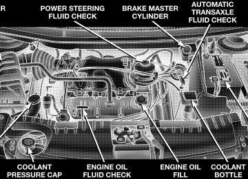
Lights Have someone observe the operation of exterior lights while you work the controls. Check turn signal and high beam indicator lights on the instrument panel. Fluid Leaks Check area under vehicle after overnight parking for fuel, engine coolant, oil or other fluid leaks. Also, if gasoline fumes are detected or fuel, power steering fluid or brake fluid leaks are suspected, the cause should be located and corrected immediately.
UNDERSTANDING THE FEATURES OF YOUR VEHICLE
CONTENTS
䡵 Mirrors . . . . . . . . . . . . . . . . . . . . . . . . . . . . . . .92
▫ Inside Day/Night Mirror . . . . . . . . . . . . . . . . .92
▫ Automatic Dimming Mirror — If Equipped . . . .92
▫ Driver’s Side Outside Mirror Auto Dimmer —If Equipped . . . . . . . . . . . . . . . . . . . . . . . . . .93
▫ Exterior Mirrors Folding Feature . . . . . . . . . . .93
▫ Outside Mirror — Driver’s Side . . . . . . . . . . . .94
▫ Outside Mirror — Passenger’s Side . . . . . . . . . .94
▫ Power Remote-Control Mirrors . . . . . . . . . . . . .94▫ Heated Remote Control Mirrors —
If Equipped . . . . . . . . . . . . . . . . . . . . . . . . . .95
▫ Illuminated Vanity Mirrors — If Equipped . . . .95䡵 Hands–Free Communication (UConnect™) —
If Equipped . . . . . . . . . . . . . . . . . . . . . . . . . . . .96
▫ Operation . . . . . . . . . . . . . . . . . . . . . . . . . . . .97
▫ Phone Call Features . . . . . . . . . . . . . . . . . . . 101
▫ Advanced Phone Connectivity . . . . . . . . . . . . 103
▫ UConnect™ System Features . . . . . . . . . . . . . 10588 UNDERSTANDING THE FEATURES OF YOUR VEHICLE
䡵 Seats . . . . . . . . . . . . . . . . . . . . . . . . . . . . . . . . 108
▫ Manual Front & Second Row Seat Adjuster . . . 108
▫ 8–Way Driver’s Power Seat — If Equipped . . . 109
▫ 4–Way Passenger’s Power Seat —If Equipped . . . . . . . . . . . . . . . . . . . . . . . . . 109
▫ Adjustable Head Restraints — If Equipped . . . 110
▫ Heated Seats — If Equipped . . . . . . . . . . . . . 111
▫ Manual Reclining Seats — If Equipped . . . . . . 112
▫ Manual Lumbar — If Equipped . . . . . . . . . . . 113
▫ Fold-In-Floor Seating . . . . . . . . . . . . . . . . . . . 113
▫ Easy Access Seating . . . . . . . . . . . . . . . . . . . 120
▫ Middle Quad Fold & Tumble Seat Removal . . . 121
▫ 50/50 Fold & Tumble Rear Seat Removal . . . . 124▫ 3 – Passenger Bench Seats . . . . . . . . . . . . . . . 126
▫ Plastic Grocery Bag Retainer . . . . . . . . . . . . . 127
▫ Rear-Most Bench Seat . . . . . . . . . . . . . . . . . . 128
▫ Rear Seat Descriptions . . . . . . . . . . . . . . . . . . 128
▫ Rear Bench Seating Flexibility . . . . . . . . . . . . 128
▫ Rear Quad And 50/50 Seating Flexibility . . . . 130
䡵 Driver Memory System — If Equipped . . . . . . . 132▫ Setting Memory Positions And Linking Remote
Keyless Entry Transmitter To Memory . . . . . . . 133
▫ Memory Position Recall . . . . . . . . . . . . . . . . . 134
▫ To Disable A Transmitter Linked To Memory . . 135
䡵 To Open And Close The Hood . . . . . . . . . . . . . 136䡵 Lights . . . . . . . . . . . . . . . . . . . . . . . . . . . . . . . 138
▫ Interior Lights . . . . . . . . . . . . . . . . . . . . . . . 138
▫ Park Lights . . . . . . . . . . . . . . . . . . . . . . . . . . 139
▫ Headlights . . . . . . . . . . . . . . . . . . . . . . . . . . 139
▫ Automatic Headlights — If Equipped . . . . . . . 140
▫ Daytime Running Lights (Canada/FleetVehicles Only)
. . . . . . . . . . . . . . . . . . . . . . . 141
▫ Lights-On Reminder . . . . . . . . . . . . . . . . . . . 141
▫ Battery Protection . . . . . . . . . . . . . . . . . . . . . 141
▫ Headlamp Delay — If Equipped . . . . . . . . . . 141
▫ Front Fog Lights — If Equipped . . . . . . . . . . . 142
䡵 Multifunction Lever . . . . . . . . . . . . . . . . . . . . . 142
▫ Turn Signals . . . . . . . . . . . . . . . . . . . . . . . . . 142UNDERSTANDING THE FEATURES OF YOUR VEHICLE 89
▫ Headlight Low/High Beam Selector Switch . . . 143
▫ Passing Light . . . . . . . . . . . . . . . . . . . . . . . . 143
▫ Windshield Wipers And Washers . . . . . . . . . . 143
䡵 Tilt Steering Column — If Equipped . . . . . . . . . 146
䡵 Traction Control Switch — If Equipped . . . . . . . 147
䡵 Rear Park Assist System — If Equipped . . . . . . . 148
䡵 Adjustable Pedals — If Equipped . . . . . . . . . . . 150
䡵 Electronic Speed Control — If Equipped . . . . . . 151
▫ To Activate . . . . . . . . . . . . . . . . . . . . . . . . . . 152
▫ To Set At A Desired Speed . . . . . . . . . . . . . . . 152
▫ To Deactivate . . . . . . . . . . . . . . . . . . . . . . . . 152
▫ To Resume Speed . . . . . . . . . . . . . . . . . . . . . 152
▫ To Vary The Speed Setting . . . . . . . . . . . . . . . 15390 UNDERSTANDING THE FEATURES OF YOUR VEHICLE
▫ To Accelerate For Passing . . . . . . . . . . . . . . . 153
䡵 Overhead Console — If Equipped . . . . . . . . . . . 154
▫ Courtesy/Reading Lights . . . . . . . . . . . . . . . . 154
▫ Sunglass Storage . . . . . . . . . . . . . . . . . . . . . . 155
▫ Compass/Temperature Display . . . . . . . . . . . 155
▫ Mini-Trip Computer . . . . . . . . . . . . . . . . . . . 158
▫ Electronic Vehicle Information Center (EVIC) —If Equipped . . . . . . . . . . . . . . . . . . . . . . . . . 159
▫ Customer Programmable Features —
If Equipped . . . . . . . . . . . . . . . . . . . . . . . . . 160
䡵 Garage Door Opener — If Equipped . . . . . . . . . 163
▫ Programming Homelink . . . . . . . . . . . . . . . . 164
▫ Canadian Programming/Gate Programming . . 167
▫ Using Homelink . . . . . . . . . . . . . . . . . . . . . . 168▫ Erasing Homelink Buttons . . . . . . . . . . . . . . . 168
▫ Reprogramming a Single Homelink Button . . . 168
▫ Security . . . . . . . . . . . . . . . . . . . . . . . . . . . . 169
䡵 Power Sunroof — If Equipped . . . . . . . . . . . . . 169
▫ Express Open Feature . . . . . . . . . . . . . . . . . . 170
▫ Wind Buffeting . . . . . . . . . . . . . . . . . . . . . . . 171
▫ Sunroof Maintenance . . . . . . . . . . . . . . . . . . . 171
䡵 Electrical Power Outlets — If Equipped . . . . . . . 172
▫ Electrical Outlet Use With Engine Off . . . . . . . 173
䡵 Convenience Tray Drawer And Cup Holders . . . 174
▫ Instrument Panel Cup Holders . . . . . . . . . . . . 174
▫ Convenience Tray And Optional Smoker’sPackage Kit
. . . . . . . . . . . . . . . . . . . . . . . . . 175
▫ Rear Cupholders . . . . . . . . . . . . . . . . . . . . . . 175䡵 Storage . . . . . . . . . . . . . . . . . . . . . . . . . . . . . . 177
▫ Front Seat Storage Bin — If Equipped . . . . . . . 177
▫ Second Row Seat Storage Bins —If Equipped . . . . . . . . . . . . . . . . . . . . . . . . . 177
▫ Overhead Rail System — If Equipped . . . . . . . 178
▫ Removable Floor Console With Fold-In-FloorSeating — If Equipped . . . . . . . . . . . . . . . . . 179
UNDERSTANDING THE FEATURES OF YOUR VEHICLE 91
▫ Removable Floor Console Without Fold-In-Floor
Seating — If Equipped . . . . . . . . . . . . . . . . . 180
▫ Rear Compartment Storage Bins . . . . . . . . . . . 184
▫ Cargo/Tub Nets . . . . . . . . . . . . . . . . . . . . . . 184
▫ Cargo Area Storage . . . . . . . . . . . . . . . . . . . . 184
䡵 Roof Luggage Rack — If Equipped . . . . . . . . . . 185
䡵 Load Leveling System . . . . . . . . . . . . . . . . . . . 18792 UNDERSTANDING THE FEATURES OF YOUR VEHICLE
MIRRORS
Inside Day/Night Mirror Adjust the mirror to center on the view through the rear window. A two point pivot system allows for horizontal and vertical adjustment of the mirror.
Annoying headlight glare can be reduced by moving the small control under the mirror to the night position (toward rear of vehicle). The mirror should be adjusted while set in the day position (toward windshield). Automatic Dimming Mirror — If equipped If the switch is in the “Auto” position the mirror will automatically adjust for annoying headlight glare from vehicles behind you. You can turn the feature on or off by pressing the button at the base of the mirror. A light in the button will illuminate to indicate when this feature is on.
Adjusting Rearview Mirror
UNDERSTANDING THE FEATURES OF YOUR VEHICLE 93
CAUTION!
To avoid damage to the mirror during cleaning, never spray any cleaning solution directly onto the mirror. Apply the solution onto a clean cloth and wipe the mirror clean.
Driver’s Side Outside Mirror Auto Dimmer — If Equipped This mirror automatically adjusts for annoying headlight glare from vehicles behind you. You can turn this feature on or off by pressing the button at the base of the Rearview Mirror. Exterior Mirrors Folding Feature All exterior mirrors are hinged and may be moved either forward or rearward to resist damage. The hinges have three detent positions; full forward, full rearward, and normal.
Automatic Dimming Mirror
94 UNDERSTANDING THE FEATURES OF YOUR VEHICLE
Outside Mirror — Driver’s Side Adjust the outside mirror to center on the adjacent lane of traffic, with a slight overlap of the view obtained on the inside mirror. Outside Mirror — Passenger’s Side Adjust the convex outside mirror so you can just see the side of your vehicle in the portion of the mirror closest to the vehicle. This type of mirror will give a much wider view to the rear, and especially of the lane next to your vehicle.
WARNING!
Vehicles and other objects seen in the right side convex mirror will look smaller and farther away than they really are. Relying too much on your right side mirror could cause you to collide with another vehicle or other object. Use your inside mirror when judging the size or distance of a vehicle seen in this convex mirror.
Power Remote-Control Mirrors Use the mirror select switch, located on the instrument panel to the left of the steering column, to adjust the view obtained in the outside mirrors. Press the rocker switch to the L or R for Left or Right mirror selection. Use the center off position to guard against accidentally moving a mirror position.
UNDERSTANDING THE FEATURES OF YOUR VEHICLE 95
Heated Remote Control Mirrors — If Equipped These mirrors are heated to melt frost or ice. This feature is activated whenever you turn on the Rear Window Defrost. Illuminated Vanity Mirrors — If Equipped An illuminated vanity mirror is on the sun visor. To use the mirror, rotate the sun visor down and swing the mirror cover upward. The lights turn on automatically. Closing the mirror cover turns off the lights. Sun Visor Extension — If Equipped The sun visor features a pull out extension for increased coverage.
Power Mirror Switches
Select a mirror and press one of the four arrows for the direction you want the mirror to move. Driver’s power mirror preselected positions can be con- trolled by the optional Memory Seat Feature. Refer to the Memory Seat paragraph in section 3 of this manual.
96 UNDERSTANDING THE FEATURES OF YOUR VEHICLE
HANDS–FREE COMMUNICATION (UConnect™) — IF EQUIPPED UConnect™ is a voice-activated, hands-free, in-vehicle communications system. UConnect™; allows you to dial your cellular phone using simple voice commands (e.g., “Call Mike Work” or “Dial 248-555-1212”). Your cellular phone’s audio is transmitted through your vehicle’s stereo system; the system will automatically mute your radio before receiving or sending a call. NOTE: The UConnect™ system use requires a cellular phone equipped with the Bluetooth ⬙Hands-Free Profile,⬙ version 0.96 or higher. For UConnect Customer Support call 1-877-855-8400 or visit (www.chrysler.com/ uconnect).
the UConnect website
UConnect™ allows you to transfer calls between the system and your cellular phone as you enter or exit your vehicle, and enables you to mute the system’s micro- phone for private conversations. The UConnect™; phone book enables you to store up to 32 names and four numbers per name. This system is driven through your Bluetooth™ Hands-Free Profile cellular phone. UConnect™ features Bluetooth™ technol- ogy - the global standard that enables different electronic devices to connect to each other without wires or a docking station, so UConnect™ works no matter where you stow your cellular phone (be it your purse, pocket, or briefcase). UConnect™ allows up to seven cellular phones to be linked to the system, and it is available in English, French, or Spanish formats (as equipped).
The rearview mirror contains the microphone for the system and the control buttons that will enable you to access the system. The diagram below shows the mirror with the appropriate buttons. Individual button behavior is discussed in the “Operation” Section.
UConnect™ Switches
The UConnect™ system can be used with any Hands Free Profile certified Bluetooth™ cellular phone. If your
UNDERSTANDING THE FEATURES OF YOUR VEHICLE 97
cellular phone has a different profile (i.e. headset profile), you will not be able to use any UConnect™ features. The UConnect™ system is fully integrated into your vehicle, including your vehicle’s stereo system. All voice prompts as well as the other party’s voice in a conversa- tion will be played over your vehicle’s stereo system. The volume of the UConnect™ system can be controlled through your normal stereo controls. The radio display will be used for visual prompts from the UConnect™ system such as caller ID. Operation Voice commands can be used in the operation of the UConnect™ system and to navigate through the UCon- nect™ menu structure. Voice commands should be given after each UConnect™ system prompt. You will be prompted for a specific command and then guided through the available options. There are two ways to give commands to the UConnect™ system:
98 UNDERSTANDING THE FEATURES OF YOUR VEHICLE
• You can say ⬙Dial⬙ at the ⬙Ready⬙ prompt. When prompted for the phone number you wish to dial, say the phone number (⬙123 456 7890⬙). • Alternatively as you become familiar with the UCon- nect™ system, you can combine the commands and say ⬙Dial 123 456 7890⬙.
Pairing a Cellular Phone to the UConnect™ System To begin using your UConnect™ system, you must pair your compatible Bluetooth™ enabled cellular phone. To complete the registration process, you will need to refer- ence your cellular phone owner’s manual. • Press the ’Phone’ button to begin. • After the ⬙Ready⬙ prompt, say ⬙Setup Phone Pairing⬙. • You will be asked to say a four-digit pin number into the UConnect™ system which you will later need to enter into your cellular phone during the cellular phone pairing process. You can enter any four-digit
pin number. You will not need to remember this pin number after the initial registration process. • The UConnect™ system will then prompt you to begin the cellular phone pairing process on your cellular phone. Please see your cellular phone user’s manual for instructions on how to complete this step. • For identification purposes, you will be prompted to give the UConnect™ system a name for your cellular phone. Each cellular phone that is paired should be given a unique phone name. • You will then be asked to give your cellular phone a priority level between 1 and 7, 1 having the highest priority. You can connect up to seven cellular phones to your UConnect™ system and the priority allows the UConnect™ system to know which cellular phone to use if multiple cellular phones are in the vehicle at the same time. For example, if a priority 3 and priority 5
cellular phone are both in the vehicle, the UConnect™system will use the priority 3 cellular phone when you make a call. You can select to use a lower priority cellular phone at any time.
Making a Phone Call Using Digit Dialing • Press the ’Phone’ button to begin. • After the ⬙Ready⬙ prompt, says ⬙Dial⬙ followed by the phone number you wish to dial. For example, you can say ⬙Dial 123 456 7890⬙. The phone number that you enter must be a valid length.
Making a Phone Call Using Your UConnect™ Phonebook • Press the “Phone” button to begin. • After the ⬙Ready⬙ prompt, says ⬙Call⬙ followed by the name and designation of a phonebook entry that you wish to dial. For example, you can say ⬙Call John Doe Work⬙.
UNDERSTANDING THE FEATURES OF YOUR VEHICLE 99
try⬙.
Add Names to Your UConnect™ Phonebook • Press the “Phone” button to begin. • After the ⬙Ready⬙ prompt, say ⬙Phonebook New En- • When prompted, say the name of the new entry. • Next, enter the number designation (e.g. “Home”, “Work”, “Mobile”, or “Pager”). This will allow you to have multiple numbers for each phonebook entry. • Recite the phone number for the phonebook entry that
you are adding.
After you are finished adding an entry into the phone- book, you will be given the opportunity to add more phone numbers to the current entry or to return to the main menu.
100 UNDERSTANDING THE FEATURES OF YOUR VEHICLE
The UConnect™ system will allow you to enter up to 32
names into the phonebook with each name having up to four associated phone numbers and designations. Edit Entries in the UConnect™ Phonebook • Press the ’Phone’ button to begin. • After the ⬙Ready⬙ prompt, say ⬙Phonebook Edit⬙. • You will then be asked for the name of the phonebook • Next, choose the number designation that you wish to edit. The choices are home, work, mobile, or pager. • Recite the new phone number for the phonebook entryentry that you wish to edit.
that you are editing.
After you are finished editing an entry in the phonebook, you will be given the opportunities to edit another entry in the phonebook, call the number you just edited, or return to the main menu.
Phonebook edit can be used to add another phone number to a name entry that already exists in the phonebook. For example, the entry John Doe may have a mobile and a home number, but you can add John Doe’s work number later through phonebook edit. Delete Entries in the UConnect™ Phonebook • Press the ’Phone’ button to begin. • After the ⬙Ready⬙ prompt, say ⬙Phonebook Delete⬙. • After you enter the phonebook delete menu, you will then be asked for the name of the phonebook entry that you wish to delete. You can either say the name of a phonebook entry that you wish to delete or you can say ⬙List Names⬙ to hear a list of the entries in the phonebook from which you can choose. To select one of the entries from the list, press the ⬙Voice Recogni- tion⬙ button while the UConnect™ system is playing the desired entry and say ⬙Delete⬙.
• After you enter the name, the UConnect™ system will ask you if you wish to delete the home, work, mobile, or pager number for this entry.
Delete All Entries in the UConnect™ Phonebook • Press the ’Phone’ button to begin. • After the ⬙Ready⬙ prompt, say ⬙Phonebook Delete All⬙. • The UConnect™ system will ask you to verify that you • After confirmation, the phonebook entries will be
wish to delete all the entries from the phonebook.
deleted.
List All Names in the UConnect™ Phonebook • Press the ’Phone’ button to begin. • After
the ⬙Ready⬙ prompt, say ⬙Phonebook List
Names⬙.
UNDERSTANDING THE FEATURES OF YOUR VEHICLE 101
phonebook entries.
• The UConnect™ system will play the names of all the • To call one of the names in the list, press the ’Voice Recognition’ button during the playing of the desired name and say ⬙Call⬙. • The UConnect™ system will then prompt you as to number designation you wish to call. • The selected number will be dialed. Phone Call Features The following feature(s) can be accessed through the UConnect™ system if the feature(s) are available on your cellular service plan. For example, if your cellular service plan provides three-way calling, this feature can be accessed through the UConnect™ system.
102 UNDERSTANDING THE FEATURES OF YOUR VEHICLE
Answer or Reject an Incoming Call - No Call Currently in Progress When you receive a call on your cellular phone, the UConnect™ system will interrupt the stereo audio and will ask if you would like to answer the call by pressing the ’Phone’ button. Press the ’Phone’ button to answer the call. To reject the call, press the ’Phone’ button until you hear a single beep indicating that the incoming call was rejected. Answer or Reject an Incoming Call - Call Currently in Progress If a call is currently in progress and you have another incoming call, press the ’Phone’ button to place the current call on hold and answer the incoming call. To reject the incoming call, you can disregard the call and continue with your current conversation.
Making a Second Call while Current Call in Progress To make a second call while you are currently in a call, press the ’Voice Recognition’ button and say ⬙Dial⬙ or ⬙Call⬙ followed by the phone number or phonebook entry you wish to call. The first call will be on hold while the second call is in progress. Putting a Call on Hold and Retrieving a Call from Hold To put a call on hold, press the ’Phone’ button until you hear a single beep which will indicate that the call has been placed on hold. To bring the call back from hold, press the ’Phone’ button. Toggling Between Two Calls If two calls are in progress (one active and one on hold), press the ’Phone’ button until you hear a single beep indicating that the active and hold status of the two calls have switched. Only one call can be placed on hold at one time.
Conference Call When two calls are in progress (one active and one on hold), press the ’Phone’ button until you hear a double beep indicating that the two calls have been joined into one conference call. Three-Way Calling To initiate three-way calling, press the ’Voice Recogni- tion’ button while a call is in progress and make a second phone call. When the second call is established, press the ’Phone’ button until you hear a double beep indicating that the two calls have been joined into one conference call. Call Termination To end a call in progress, press the ’Phone’ button. All calls in progress will be terminated.
UNDERSTANDING THE FEATURES OF YOUR VEHICLE 103
Phone Redial • Press the ’Phone’ button to begin. • After the ⬙Ready⬙ prompt, say ⬙Redial⬙. • The UConnect™ system will call the last number that was dialed on your cellular phone. This may not be the last number dialed by your UConnect™ system.
Advanced Phone Connectivity
Transferring an Active Call between the UConnect™ System and Your Cellular Phone The UConnect™ system allows ongoing calls to be trans- ferred to your cellular phone or to the UConnect™ system without terminating the call. To transfer an ongo- ing call from your cellular phone to the UConnect™ system or vice versa, press the ’Voice Recognition’ button and say ⬙Transfer Call⬙.
104 UNDERSTANDING THE FEATURES OF YOUR VEHICLE
Delete Paired Cellular Phones • Press the ’Phone’ button to begin. • After the ⬙Ready⬙ prompt, say ⬙Setup Phone Pairing⬙. • At the next prompt, say ⬙Delete⬙. • You will be asked to say the name of the phone that you wish to delete. You can either say the name of the phone that you wish to delete or you can say ⬙All⬙ to delete all the phones.
Connect or Disconnect the Connection between the UConnect™ System and Your Cellular Phone Your cellular phone can be paired with many different electronic devices, but can only be actively ⬙connected⬙ with one electronic device at a time. If you would like to connect or disconnect the Blue- tooth™ connection between a paired cellular phone and the UConnect™ system, follow the instruction described in your cellular phone user’s manual. List Paired Cellular Phone Names • Press the ’Phone’ button to begin. • After the ⬙Ready⬙ prompt, say ⬙Setup List Phones⬙ and the UConnect™ system will play the phone names of all paired cellular phones in order from highest prior- ity to lowest priority.
Select a Lower Priority Paired Cellular Phone • Press the ’Phone’ button to begin. • After the ⬙Ready⬙ prompt, say ⬙Setup Select Phone⬙. • When prompted, say the phone name of the cellular phone you wish to use, or say ⬙List Phones⬙ to hear a list of all the phones that have been paired to your UConnect™ system. To select a phone from the list, press the ’Voice Recognition’ button and say ⬙Select⬙. • The lower priority phone will only be used for the next phone call. After that, the UConnect™ system will return to using the highest priority phone in the vehicle.
UNDERSTANDING THE FEATURES OF YOUR VEHICLE 105
UConnect™ System Features
Barge In - Touch Tone Phone Inputs You can use your UConnect™ system to access a voice mail system, an automated service, or any other phone number that you can dial with any phone. When calling a number with your UConnect™ system that normally requires you to enter in a touch-tone sequence on your cellular phone keypad, you can push the ’Voice Recogni- tion’ button and say the sequence you wish to enter followed by ⬙Send⬙. For example, if required to enter your pin number, you can press the ’Voice Recognition’ button and say ⬙3 7 4 6 Send⬙, or whatever you have made your pin. This method can also be used in instances where you are pressing a number on your keypad to navigate through a menu structure or to enter a number for a pager.
106 UNDERSTANDING THE FEATURES OF YOUR VEHICLE
Barge In - Overriding Prompts The ’Voice Recognition’ button can be used when you wish to skip part of a prompt and issue your voice recognition command immediately. For example, if a prompt is playing ⬙Would you like to pair a phone, clear aѧ⬙, you could press the ’Voice Recognition’ button and say ⬙Pair A Phone⬙ to select that option without having to listen to the rest of the voice prompt. Language Selection To change the language that the UConnect™ system is using, press the ’Phone’ button and say the name of the language you wish to switch to (English, Español, or Français as equipped). After selecting one of the lan- guages, all prompts and voice commands will be in the selected language.
Turning Confirmation Prompts On/Off Turning confirmation prompts off will stop the system from confirming your choices (e.g. the UConnect™ sys- tem will not repeat a phone number before you dial it). • Press the ’Phone’ button to begin. • After the ⬙Ready⬙ prompt, say ⬙Setup Confirmation⬙. The UConnect™ system will play the current confir- mation prompt status and you will be given the choice to change it.
Low Signal, Battery Strength, and Roam Notification The UConnect™ system will provide notification to inform you if your cellular phone is in roaming status, has low signal strength, or has a low battery when you are trying to place a phone call.
Dialing Using the Cellular Phone Keypad You can dial a phone number with your cellular phone keypad and still use the UConnect™ system. By dialing a number with your paired Bluetooth™ cellular phone, the audio will be played through your vehicle’s stereo sys- tem. The UConnect™ system will work the same as if you dialed the number using voice recognition. Mute/Unmute When you mute the UConnect™ system, you will still be able to hear the conversation coming from the other party, but the other party will not be able to hear you. In order to mute the UConnect™ system press the ’Voice Recognition’ button and say ⬙Mute⬙. In order to unmute the UConnect™ system; press the ’Voice Recognition’ button and say ⬙Unmute⬙.
UNDERSTANDING THE FEATURES OF YOUR VEHICLE 107
Help If you need assistance at any prompt or if you want to know what your options are at any prompt, say ⬙Help⬙. The UConnect™ system will play all the options at any prompt if you ask for help. Cancel At any prompt, you can say ⬙Cancel⬙ and you will be returned to the previous menu. Emergency Assistance If you are in an emergency, say ⬙Dial Emergency⬙ or ⬙Call Emergency⬙ and the UConnect™ system will instruct your cellular phone to call 911. Towing Assistance If you need towing assistance, say ⬙Dial Towing Assis- tance⬙ or ⬙Call Towing Assistance⬙. Please refer to the 24-Hour Towing Assistance coverage details in the DaimlerChrysler Motors Company 24-Hour Towing As- sistance Program Guide.
108 UNDERSTANDING THE FEATURES OF YOUR VEHICLE
SEATS
Manual Front & Second Row Seat Adjuster The adjusting bar is located under the front of the seat. Pull the bar up and move the seat to the desired position. Release the bar to lock the seat into position.
Using body pressure, move forward and rearward on the seat to be sure the seat adjusters have latched.
WARNING!
Adjust the seat only while the vehicle is parked. Adjusting a seat while the vehicle is moving is dangerous. The sudden movement of the seat could cause you to lose control. The seat belt might not be properly adjusted and you could be injured.
Manual Seat Adjuster
8–Way Driver’s Power Seat — If Equipped The driver’s power seat switches are located on the outboard side of the seat. The front switch controls up/down, forward/rearward, and tilt adjustment. The rear switch controls the seatback recline adjustment.
4–Way Passenger’s Power Seat — If Equipped The passenger’s power seat switches are located on the outboard side of the seat. The front switch controls forward and rearward adjustment. The rear switch con- trols the seatback recline adjustment.
UNDERSTANDING THE FEATURES OF YOUR VEHICLE 109
CAUTION!
Do not place any article under a power seat or impede its ability to move as it may cause damage to the seat controls. Seat travel may become limited if movement is stopped by an obstruction in the seat’s path.
Driver Power Seat Switch
110 UNDERSTANDING THE FEATURES OF YOUR VEHICLE
Adjustable Head Restraints — If Equipped Head restraints can reduce the risk of whiplash injury in the event of impact from the rear. Pull up or push down on the head restraint so that the upper edge is as high as practical. To raise the head restraint, pull up on the head restraint. To lower the head restraint, depress the release tab located at the base of the head restraint and push down on the head restraint.
Adjustable Head Restraints
Heated Seats — If Equipped This feature heats the front driver and passenger seats. The controls for the heated seats are located on the instrument panel above the radio. You may choose LOW, HIGH or No Heat. The switch position as well as an indicator light will show when the LOW or HIGH heat is ON.
UNDERSTANDING THE FEATURES OF YOUR VEHICLE 111
Heated Seat Switches
112 UNDERSTANDING THE FEATURES OF YOUR VEHICLE
Manual Reclining Seats — If Equipped The recliner mechanism control is on the outboard side of the seat. To recline, lean forward slightly, lift the lever, then push back to the desired position and release the lever. Lean forward and lift the lever to return the seatback to its normal position. Using body pressure, lean forward and rearward on the seat to be sure the seatback has latched.
Manual Reclining Seat Control
WARNING!
Do not ride with the seatback reclined so that the shoulder belt is no longer resting against your chest. In a collision you could slide under the seat belt and be seriously or fatally injured. Use the recliner only when the vehicle is parked.
Manual Lumbar — If Equipped The lumbar adjustment handle is located inboard under the armrest. To increase the support, rotate the handle down.
UNDERSTANDING THE FEATURES OF YOUR VEHICLE 113
Manual Lumbar Control
Fold-in-Floor Seating On vehicles equipped with fold-in-floor seating, the second and third row seats may be folded into the floor for convenient storage.
114 UNDERSTANDING THE FEATURES OF YOUR VEHICLE
To Fold Second Row Seats 1. Move the front seat fully forward, lower the head restraint and raise the armrests on the second row seat. 2. Pull up on the storage bin latch to open cover.
3. Pull up on the seatback recliner lever located on the outboard side of the seat and fold the seatback down.
Storage Bin Cover
Seatback Release Lever
NOTE: The cupholder must be in the closed position before the seat can be tumbled into the floor.
4. Pull rearward on the release strap located at the rear of the seat and tumble the seat forward into the storage bin.
UNDERSTANDING THE FEATURES OF YOUR VEHICLE 115
To Unfold Second Row Seats 1. Open the storage bin cover. 2. Pull up on the handle to lift the seat out of the storage bin and push the seat rearward to latch the seat anchors.
5. Close the storage bin cover.
Seat Release Strap
Seat Handle
116 UNDERSTANDING THE FEATURES OF YOUR VEHICLE
3. Pull up on the seatback recliner lever located on the outboard side of the seat, to return the seatback to its full upright position.
To Fold Third Row Seats 1. Lower the head restraint to its full down position. 2. Pull release strap marked “1” located on the rear of the seat to lower the seatback.
Seatback Release Lever
4. Close the storage bin cover and adjust the head restraint to the desired position.
Release Strap 1
3. Pull release strap marked “2” to release the anchors.
UNDERSTANDING THE FEATURES OF YOUR VEHICLE 117
4. Pull release strap marked “3” and tumble the seat rearward into the storage bin.
Release Strap 2
Release Strap 3
118 UNDERSTANDING THE FEATURES OF YOUR VEHICLE
To Unfold Third Row Seats 1. Pull up on the assist strap to lift the seat out of the storage bin and push the seat forward until the anchors latch.
3. Pull release strap marked “3” to return the seatback to its full upright position.
2. Pull release strap marked “1” to unlock the recliner.
Assist Strap
4. Adjust the head restraint to the desired position.
Release Strap 3
WARNING!
In a collision, you or others in your vehicle could be injured if seats are not properly latched to their floor attachments. Always be sure the seats are fully latched.
Tailgate Mode 1. Pull release strap “2”, then pull release strap “3” to rotate the entire seat rearward.
UNDERSTANDING THE FEATURES OF YOUR VEHICLE 119
Release Straps 2 & 3
120 UNDERSTANDING THE FEATURES OF YOUR VEHICLE
2. To restore the seat to its upright position, lift up on the seatback and push forward until the anchors latch.
WARNING!
To avoid serious injury or death, never operate the vehicle with occupants in the third row seat, while in the tailgate mode.
Easy Access Seating The passenger’s and driver’s side second row seats can be tilted forward for easy access to the third row seat or rear cargo area. To tilt the seat on vehicles equipped with quad seats, pull up on the release handle located on the outboard side of the seat and tilt the seat fully forward. To return the seat, lower the seat and ensure that it is fully latched.
Tilting Quad Seat
To tilt the seat on vehicles equipped with fold-in-floor seating, pull forward on the release strap located on the front of the seat between the seat back and seat cushion and tilt the seat fully forward. To return the seat, lower the seat and ensure that it is fully latched.
UNDERSTANDING THE FEATURES OF YOUR VEHICLE 121
WARNING!
In the event of a collision you could be injured if the seat is not fully latched.
Middle Quad Fold & Tumble Seat Removal
1. Remove any obstructions from the floor in front of the seat. 2. Lower the head restraint to its full downward position and ensure that the cupholder is closed.
Tilting Fold-in-Floor Seat
122 UNDERSTANDING THE FEATURES OF YOUR VEHICLE
3. Pull up on the seatback release lever located on the outboard side of the seat and fold the seatback down. If the head restraint contacts the rear of the front seat, move the front seat forward on its tracks.
4. Pull up on the release handle and tumble the seat fully forward.
Seatback Release Lever
Seat Release Handle
5. Pull the release bar located at the bottom front edge of the seat to disengage the front attachments.
Release Bar Location
6. The seat assembly can now be removed from the vehicle and moved on its Easy Out威 Rollers.
UNDERSTANDING THE FEATURES OF YOUR VEHICLE 123
To reinstall the seat, remove any obstructions from the floor in front of the seat and ensure the head restraint is in its full downward position. Align the seat in the floor tracks and tilt the seat forward to engage the front floor attachments, then tilt the seat rearward and push down to engage the rear attachments. Pull the seatback release lever to return the seatback to its full upright position. Ensure that the seatback is fully latched in the upright position.
WARNING!
In a collision, you or others in your vehicle could be injured if seats are not properly latched to their floor attachments. Always be sure the seats are fully latched.
124 UNDERSTANDING THE FEATURES OF YOUR VEHICLE
50/50 Fold & Tumble Rear Seat Removal
1. Lower the head restraint and pull up on release lever “1” to fold the seatback down.
2. Pull up on release lever “2” and tumble the seat fully forward.
Release Lever Location
Release Lever 2 Location
3. Pull the release strap “3” located at the bottom of the seat to disengage the front attachments.
Release Strap Location
UNDERSTANDING THE FEATURES OF YOUR VEHICLE 125
4. The seat assembly can now be removed from the vehicle and moved on its Easy Out威 Rollers. To reinstall the 50/50 rear seat, lower the head restraint to the full down position, tilt the seat forward and engage the front floor attachments, then tilt the seat rearward to engage the rear attachments. Pull the seatback release lever to return the seatback to its full upright position. Ensure that the seatback is fully latched in the upright position.
WARNING!
In a collision, you or others in your vehicle could be injured if seats are not properly latched to their floor attachments. Always be sure the seats are fully latched.
126 UNDERSTANDING THE FEATURES OF YOUR VEHICLE
3 – Passenger Bench Seats Release levers are located on the rear leg assemblies, near the floor. To remove the seat, squeeze each release handle and rotate downwards to deploy the wheels. A lock indicator button pops up when the seat is unlocked. The seat assembly can now be removed from the vehicle and moved on its Easy Out威 Rollers.
Release Levers
To reinstall the seat, align the seat into the detent posi- tions on the floor. Squeeze the release handle and rotate upward until the lock indicator button returns into the handle.
WARNING!
If not properly latched, the bench seats could be- come loose. Personal injuries could result. After reinstalling these seats, be sure the red indicator button on the release handles return into the handles.
Plastic Grocery Bag Retainer Retainer hooks which will hold plastic grocery bag handles are built into the seatbacks of all rear seats and some front seats. The floor supports the partial weight of the bagged goods.
UNDERSTANDING THE FEATURES OF YOUR VEHICLE 127
Grocery Bag Holders
128 UNDERSTANDING THE FEATURES OF YOUR VEHICLE
Rear-Most Bench Seat The seat position can be adjusted fore and aft to any of three positions - normal (rearward), intermediate, and full forward. In this way varying needs for legroom and cargo space behind the seat can be accommodated.
The release lever is below the seat and is accessible from the front and back of the seat. Rear Seat Descriptions 7 Passenger Model — 2– passenger bucket seats in the second position and 3– passenger bench seat or 50/50
bench seat in the third position. All rear seats are remov- able. Rear Bench Seating Flexibility The 3– passenger bench seat may be adjusted to any of 3
positions on its tracks while installed in the vehicle. The bench seat may also be moved to the second seating position or removed from the vehicle.Release Lever Location
1. Normal Seating— The 2nd and 3rd row seats are installed. The 3rd row bench seat is in the full rear position on the tracks.
UNDERSTANDING THE FEATURES OF YOUR VEHICLE 129
3. Additional Storage— The 2nd and 3rd row seats installed. The 3rd row bench seat is in the full forward position on the tracks and one or both of the rear seatbacks are folded down.
2. Increased Storage— Increased storage area is provided by adjusting 3rd row bench seat to the intermediate track position. Rear seat- ing for 3 passengers (children) is still provided.
130 UNDERSTANDING THE FEATURES OF YOUR VEHICLE
4. Auxiliary Seating— The middle quad seats are removed from the vehicle. The 3– passenger bench seat can be installed in either the second or third row.
1. Normal Seating— The 2nd and 3rd row seats are installed. Both seatbacks are in the upright position.
Rear Quad and 50/50 Seating Flexibility The seats may be used with either or both seatbacks folded forward for additional storage space, or with either or both seats removed from the vehicle. Both 50/50
seats may also be moved to the 2nd row seating position when the middle quad seats are removed.2. Increased Storage— Increased storage area is provided by folding either or both seatbacks. With one seatback folded forward, rear seating for another occupant is still provided. Either or both seats may Fold and Tumble forward for more storage space. For maximum storage, remove the head restraint and place on the seat cushion, then fold the seatback over the head restraint by lifting lever “1” and tumble the seat forward by lifting lever “2”.
NOTE: Driving with the 2nd-row seats in the tumbled position is not recommended when passengers occupy the 3rd row seats. This position is intended only to increase available cargo area without requiring removal of the seats. Do not leave the head restraint stored between the cushions for extended periods of time or inadvertent damage to the seat cover or head restraint may occur.
3. Additional Storage— The 2nd row seats are installed in the middle seating position. Either or both of the rear seats are removed from the vehicle.
UNDERSTANDING THE FEATURES OF YOUR VEHICLE 131
4. Auxiliary Seating— The 2nd row seats are removed from the vehicle. Then the third row seats can be installed in either the rear or middle seat position. If the seat is not occupied, the seatback can be folded forward to obtain additional cargo space. To fold the seatback forward, pull the handle labeled “1” located behind the seat on the passenger side. The seatback will latch in the folded position. To assure the seatback is latched in the folded position, additional downward pressure on the seatback may be required when folding. The same lever is used to return the seatback to the upright position. NOTE: The head restraints are removable, if needed. To remove them, press the release tab on the right side of the base of the head restraint.
DRIVER MEMORY SYSTEM — IF EQUIPPED Once programmed, the memory buttons 1 and 2 on the driver’s door panel can be used to recall the driver’s seat, driver’s outside mirror, adjustable brake and accelerator pedals, and radio station preset settings. Your Remote Keyless Entry transmitters can also be programmed to recall the same positions when the Unlock button is pressed.
132 UNDERSTANDING THE FEATURES OF YOUR VEHICLE
WARNING!
• Not all head restraints in this vehicle are the same. Head restraints from one seating position should not be removed and installed in any other seating posi- tion. In a collision, serious injury or death may result if the proper head restraint is not installed on each seat. • The cargo area in the rear of the vehicle should not be used as a play area by children. They could be seriously injured in a collision. Children should be seated and using the proper restraint system. • It is extremely dangerous to ride in a cargo area, inside or outside of a vehicle. In a collision, people riding in these areas are more likely to be seriously injured or killed. • Do not allow people to ride in any area of your vehicle that is not equipped with seats and seat belts. • Be sure everyone in your vehicle is in a seat and
using a seat belt properly.
UNDERSTANDING THE FEATURES OF YOUR VEHICLE 133
Setting Memory Positions and Linking Remote Keyless Entry Transmitter to Memory
NOTE: Each time the SET (S) button and a numbered button (1 or 2) are pressed, you erase the memory settings for that button and store a new one. 1. Insert the ignition key and turn the ignition switch to the ON position. 2. Press the driver door memory button number 1 if you are setting the memory for driver 1, or button number 2
if you are setting the memory for driver 2. The system will recall any stored settings. Wait for the system to complete the memory recall before continuing to step 3. 3. Adjust the driver’s seat, recliner, and driver’s side view mirror to the desired positions. 4. Adjust the brake and accelerator pedals to the desired positions.Driver Memory Switches
Your vehicle may have been delivered with two Remote Keyless Entry transmitters. One or both transmitters can be linked to either memory position. The memory system can accommodate up to four transmitters, each one linked to either of the two memory positions.
134 UNDERSTANDING THE FEATURES OF YOUR VEHICLE
5. Turn on the radio and set the radio station presets (up to 10 AM and 10 FM stations can be set). 6. Turn the ignition switch to the OFF position and remove the key. 7. Press and release the SET (S) button located on the driver’s door. A chime will sound signaling that you are in the memory set mode. 8. Within 5 seconds, press and release memory button 1
or 2 on the driver’s door. A chime will sound signaling to you that the driver memory has been set. The next step must be performed within 5 seconds if you desire to also use a Remote Keyless Entry transmitter to recall memory positions. 9. Press and release the LOCK button on one of the transmitters. A chime will sound signaling to you that the transmitter has been successfully linked to memory.10. Insert the ignition key and turn the ignition switch to the ON position. 11. Select ⬙Remote Linked to Memory⬙ in the Electronic Vehicle Information Center (EVIC) and enter ⬙Yes⬙ or select ⬙Use Factory Settings⬙ from the EVIC and enter ⬙Yes⬙. Refer to the Customer Programmable features in the Electronic Vehicle Information Center (EVIC) section for more information. 12. Repeat the above steps to set the next memory position using the other numbered memory button or to link another Remote Keyless Entry transmitter to memory. Memory Position Recall
NOTE: The vehicle must be in Park to recall memory positions. If a recall is attempted when the vehicle is not in Park, a message will be displayed in the Electronic Vehicle Information Center (EVIC).
To recall the memory settings for driver one, press memory button number 1 on the driver’s door or the Unlock button on the Remote Keyless Entry transmitter linked to memory position 1. To recall the memory setting for driver two, press memory button number 2 on the driver’s door or the Unlock button on the Remote Keyless Entry transmitter linked to memory position 2. A recall can be cancelled by pressing any of the memory buttons on the drivers door during a recall (S, 1, or 2). When a recall is cancelled, the driver’s seat, driver’s mirror, and the pedals stop moving. A delay of one second will occur before another recall can be selected.
UNDERSTANDING THE FEATURES OF YOUR VEHICLE 135
To Disable A Transmitter Linked to Memory
1. Turn the ignition switch to the OFF position and remove the key. 2. Press and release memory button number 1. The system will recall any memory settings stored in position 1. Wait for the system to complete the memory recall before continuing to step 3. 3. Press and release the memory SET (S) button located on the driver’s door. A chime will sound signaling that you are in the memory set mode. 4. Within 5 seconds, press and release memory button 1
on the driver’s door. A chime will sound signaling to you that the driver memory has been set. 5. Within 5 seconds, press and release the UNLOCK button on the Remote Keyless Entry transmitter. A chime will sound signaling to you that the transmitter link has been successfully disabled.136 UNDERSTANDING THE FEATURES OF YOUR VEHICLE
To disable another transmitter linked to either memory position, repeat steps 1-5 for each transmitter. NOTE: Once programmed, all transmitters linked to memory can be easily enabled or disabled at one time. Refer to the Remote Linked to Memory ⬙Customer Pro- grammable Features⬙ in the Electronic Vehicle Informa- tion Center (EVIC) for more information.
TO OPEN AND CLOSE THE HOOD To open the hood, two latches must be released. First pull the hood release lever located under the left side of the instrument panel.
Hood release Lever
Next, push to the left the safety catch located under the front edge of the hood, near the center.
Hood Safety Catch
Use the hood prop rod to secure the hood in the open position.
UNDERSTANDING THE FEATURES OF YOUR VEHICLE 137
To prevent possible damage, do not slam the hood to close it. Lower the hood until it is open approximately 12
inches (30 cm) and then drop it. This should secure both latches. Never drive your vehicle unless the hood is fully closed, with both latches engaged.WARNING!
If the hood is not fully latched, it could fly up when the vehicle is moving and block your forward vision. You could have a collision. Be sure all hood latches are fully latched before driving.
138 UNDERSTANDING THE FEATURES OF YOUR VEHICLE
LIGHTS All of the lights, except the hazard warning lights, are controlled by switches to the left of the steering column on the instrument panel.
Headlight Switch
Interior Lights Interior lights are turned on when a door or liftgate is opened, the keyless entry transmitter is activated, or when the dimmer control is moved to the extreme top. The interior lights will automatically turn off in about 15
minutes if any of the following occur. • A door, sliding door or the liftgate is left open. • Any overhead reading light is left on. • If the dimmer control is in the extreme top position. NOTE: The key must be out of the ignition switch or the ignition switch must be in the OFF position for this feature to operate.Park Lights
Turn this switch to the first detent to turn the park lights on. This also turns on all instrument panel
lighting. Headlights
Turn the headlight switch to the 2nd detent to turn the headlights and park lights on. This also turns on all instrument panel lighting.
To change the brightness of the instrument panel lights, rotate the dimmer control up or down.
UNDERSTANDING THE FEATURES OF YOUR VEHICLE 139
Dimmer Control
With the park lights or headlights on, rotating the dimmer control for the interior lights on the in- strument panel upward will in- crease the brightness of the instru- ment panel lights.
Dome Light Position
Rotate the dimmer control com- pletely upward to the second de- tent (extreme top position) to turn on the interior lights, except the front reading/courtesy lights. The interior remain on when the dimmer control is in this position.
lights will
140 UNDERSTANDING THE FEATURES OF YOUR VEHICLE
Interior light Defeat (OFF)
Rotate the dimmer control to the OFF position (extreme bottom). The interior lights will remain off when the doors or liftgate are open.
Parade Mode (Daytime Brightness Feature)
Rotate the dimmer control to the first detent. This feature brightens the odometer, radio and overhead displays when the park lights or headlights are on.
Automatic Headlights — If Equipped
This system automatically turns your headlights ON or OFF based on ambient light levels. To turn the system ON, turn the headlight switch to the extreme counter- clockwise position. When the sys- tem is ON, the Headlight Time Delay feature is also ON. This means your headlights will stay ON for up to 90 seconds after you turn the ignition switch OFF. To turn the Automatic System OFF, turn the headlight switch clockwise to the OFF position. NOTE: The engine must be running before the head- lights will come ON in the Automatic mode.
Daytime Running Lights (Canada/Fleet Vehicles Only) The Daytime Running Lights will come on whenever the vehicle is running, the headlights are off, and the parking brake is off. The headlight switch must be used for normal night time driving. Lights-on Reminder If the headlights or the park lights are left on, or if the dimmer control is in the extreme top position after the ignition switch is turned off, a chime will sound when the driver’s door is opened. Battery Protection This feature provides battery protection to avoid wearing down the battery if the headlights, park lights, or front fog lights are left on for extended periods of time when the ignition switch is in the LOCK position. After 3
minutes of the ignition switch being in the LOCK posi- tion and the headlight switch in any position other thanUNDERSTANDING THE FEATURES OF YOUR VEHICLE 141
OFF or AUTO, the lights will turn off automatically until the next cycle of the ignition switch or headlight switch. The battery protection feature will be disabled if the ignition switch is turned to any other position other than LOCK during the 3 minute delay. Headlamp Delay — If Equipped This feature provides the safety of headlight illumination for up to 90 seconds, when leaving your vehicle in an unlighted area. To activate the delay feature, turn off the ignition switch while the headlights are still on. Then turn off the headlights within 45 seconds. The 90 second delay inter- val begins when headlight switch is turned off. If the headlights or park lights are turned back on or the ignition switch is turned on, the delay will be cancelled. The driver can choose, when exiting the vehicle, to have the headlamps remain on for 30, 60, or 90 seconds, or not
142 UNDERSTANDING THE FEATURES OF YOUR VEHICLE
remain on. refer to Electronic Vehicle Information Center (EVIC) “Customer Programmable Features” for more information. If the headlights are turned off before the ignition, they will turn off in the normal manner. NOTE: The headlights must be turned off within 45
seconds of turning the ignition off to activate this feature. Front Fog Lights — If EquippedTo activate the front fog lights, turn on the park lights or the low beam headlights and pull out on the headlight switch control knob. An indicator in the headlight switch shows that the front fog lights are on. Pressing the headlight switch control knob in will turn the front fog lights off.
MULTIFUNCTION LEVER
Turn Signals Move the Multifunction Lever up or down and the arrows on each side of the base instrument cluster or Information Center flash to indicate proper operation of the front and rear turn signal lights. You can signal a lane change by moving the lever partially up or down. If either indicator flashes at a rapid rate, check for a defective outside turn signal light bulb. If one of the indicators fails to light when the lever is moved, it would suggest that the indicator light is defective.
UNDERSTANDING THE FEATURES OF YOUR VEHICLE 143
Headlight Low/High Beam Selector Switch Pull the multifunction lever toward the steering wheel to switch the headlights between HIGH and LOW beam. Passing Light You can signal another vehicle with your headlights by lightly pulling the multifunction lever toward the steer- ing wheel. This will cause the headlights to turn on at high beam and remain on until the lever is released. Windshield Wipers and Washers The wipers and washers are operated by a switch in the multifunction lever. Rotate the end of the lever to select the desired wiper speed.
Turn Signal Switch
Turn Signal Warning If the vehicle electronics sense that the vehicle has traveled at over 18 mph (29 km/h) for about one mile with the turn signals on, a chime will sound to alert the driver.
144 UNDERSTANDING THE FEATURES OF YOUR VEHICLE
NOTE: Always remove any build-up of snow that prevents the windshield wiper blades from returning to the OFF position. If the windshield wiper switch is turned OFF and the blades cannot return to the OFF position, damage to the wiper motor may occur.
To use the washer, press the end of the multifunction lever in when spray is desired, the washers will spray for a maximum of 20 seconds or until the lever is released. If another washer cycle is desired the end of the lever must be pressed again to get another 20 second washer cycle. If the lever is depressed while in the delay range, the wipers will operate for several seconds after the lever is released, and then resume the intermittent interval pre- viously selected. If the end of the lever is depressed while in the OFF position, the wipers will operate for approximately two wipe cycles, then turn OFF.
Windshield Wiper/Washer Control
WARNING!
Sudden loss of visibility through the windshield could lead to an accident. You might not see other vehicles or other obstacles. To avoid sudden icing of the windshield during freezing weather, warm the windshield with defroster before and during wind- shield washer use.
UNDERSTANDING THE FEATURES OF YOUR VEHICLE 145
Intermittent Wiper System Use the intermittent wipers when weather conditions make a single wiping cycle, with a variable pause be- tween cycles, desirable. Rotate the end of the lever to the first detent position, then turn the end of the lever to select the desired delay interval. The delay can be regulated from a maximum of about 20 seconds between cycles, to a cycle every 2
seconds. The time delay will be doubled if the vehicle speed is less than 10 mph (16 km/h).146 UNDERSTANDING THE FEATURES OF YOUR VEHICLE
TILT STEERING COLUMN — IF EQUIPPED To tilt the column, pull the small lever, located behind the turn signal control, toward you and move the wheel up or down, as desired. Release the lever to lock the wheel firmly in place.
WARNING!
Tilting the steering column while the vehicle is moving is dangerous. Without a stable steering col- umn, you could lose control of the vehicle and have an accident. Adjust the column only while the ve- hicle is stopped. Be sure it is locked before driving.
Tilt Steering Column Control
TRACTION CONTROL SWITCH — IF EQUIPPED The TRAC indicator, located below the instrument clus- ter odometer, will light up when the Traction Control is in use. To turn the system OFF, press the TRAC OFF switch located on the steering column, until the TRAC OFF indicator below the instrument cluster odometer lights up.
UNDERSTANDING THE FEATURES OF YOUR VEHICLE 147
Traction Control Switch
To turn the system back ON, press the switch a second time until the TRAC OFF indicator turns OFF.
148 UNDERSTANDING THE FEATURES OF YOUR VEHICLE
NOTE: • The Traction Control System indicator comes on each time the ignition switch is turned ON. This will occur even if you used the switch to turn the system OFF. • The Traction Control will make buzzing or clicking
sounds when in operation.
REAR PARK ASSIST SYSTEM — IF EQUIPPED This system is used to help drivers determine if an obstacle is in the way of the vehicle while it is backing up in addition to the use of inside rearview and outside mirrors. When the driver selects Reverse the system scans for objects behind the vehicle using four sensors located in the rear bumper. Objects can be detected from up to 71
inches (180 cm). A warning display above the rear window provides both visible and audible warnings indicating the range of the object.Rear Park Assist Indicator
WARNING!
Drivers must be careful when backing up even when using the Rear Park Assist System. Always check carefully behind your vehicle, look behind you, and be sure to check for pedestrians, other vehicles, obstructions, and blind spots before backing up. Failure to do so can result in serious personal injury or death.
The display contains two sets of yellow and red LEDs that the driver can see in the rear view mirror. Each side of the vehicle has its own warning LEDs. The system provides a visual warning by illuminating one or more yellow LEDs as the vehicle gets closer to the object. As the vehicle continues to approaches the object, one red LED is illuminated and the system emits a series of short
UNDERSTANDING THE FEATURES OF YOUR VEHICLE 149
beeps. The tone will remain constant and both red LEDs are illuminated once the vehicle is within 12 inches (30.5
cm) of the object. The system can be turned on or off through the electronic vehicle information center (EVIC) when the vehicle is in PARK. If the rear park assist system is turned off, a single chime will sound and the EVIC will display the following message “REAR PARK ASSIST OFF”, when the vehicle is in reverse. NOTE: • Ensure that the rear bumper is free of dirt and debris • Jackhammers, large trucks, and other vibrations couldto keep the system operating properly.
affect the performance of the system.
If Service Park Assist System appears in the EVIC after making sure the rear bumper is clean please see your authorized dealer.
150 UNDERSTANDING THE FEATURES OF YOUR VEHICLE
ADJUSTABLE PEDALS — IF EQUIPPED This feature allows both the brake and accelerator pedals to move toward or away from the driver to provide improved position with the steering wheel. The adjust- able pedal system is designed to allow a greater range of driver comfort for steering wheel tilt and seat position. The switch is located on the right side of the steering column.
Adjustable Pedal Switch
Press the button forward to move the pedals forward (toward the front of the vehicle). Press the button rearward to move the pedals rearward (toward the driver). • The pedals can be adjusted with the ignition OFF.
• The pedals can be adjusted while driving. • The pedals cannot be adjusted when the vehicle is in R (Reverse) or when the Speed Control System is ON. The following messages will be displayed on vehicles equipped with the Electronic Vehicle Information Sys- tem (EVIC) if the pedals are attempted to be adjusted when the system is locked out (“Adjustable Pedal Disabled — Cruise Control Engaged” or “Adjustable Pedal Disabled — Vehicle In Reverse”).
CAUTION!
Do not place any article under the adjustable pedals or impede its ability to move as it may cause damage to the pedal controls. Pedal travel may become limited if movement is stopped by an obstruction in the adjustable pedal’s path.
UNDERSTANDING THE FEATURES OF YOUR VEHICLE 151
ELECTRONIC SPEED CONTROL — IF EQUIPPED When engaged, this device takes over the accelerator operation at speeds greater than 30 mph (50 km/h).
Speed Control Switches
152 UNDERSTANDING THE FEATURES OF YOUR VEHICLE
To Activate: Push the “ON/OFF” button once and the CRUISE indi- cator located below the instrument cluster odometer will illuminate showing the electronic speed control system is on. To turn the system OFF, push the “ON/OFF” button again and the system and indicator will turn off.
WARNING!
Leaving the Electronic Speed Control system on when not in use is dangerous. You could accidently set the system or cause it to go faster than you want. You could lose control and have an accident. Always leave the system OFF when you aren’t using it.
To Set At A Desired Speed:
When the vehicle has reached the desired speed, press and release the “SET” button. Release the accelerator and the vehicle will operate at the selected speed. To Deactivate: A soft tap on the brake pedal, pushing the “CANCEL” button or normal braking while slowing the vehicle will deactivate the speed control without erasing the set speed memory. Pushing the “ON/OFF” button to the OFF position or turning off the ignition erases the set speed memory. To Resume Speed: To resume a previously set speed, push and release the “RESUME/ACCEL” button. Resume can be used at any speed above 25 mph (40 km/h).
To Vary the Speed Setting: When the speed control is set, speed can be increased by pressing and holding the “RESUME/ACCEL” button. When the button is released, a new set speed will be established. Tapping the “RESUME/ACCEL” button once will result in a 2 mph (3 km/h) speed increase. Each time the button is tapped, speed increases so that tapping the button three times will increase speed by 6 mph (10 km/h), etc. To decrease speed while speed control is set, press and hold the “COAST” button. Release the button when the desired speed is reached, and the new speed will be set. Tapping the “COAST” button once will result in a 1 mph (2 km/h) speed decrease. Each time the button is tapped, speed decreases.
UNDERSTANDING THE FEATURES OF YOUR VEHICLE 153
To Accelerate For Passing: Depress the accelerator as you would normally. When the pedal is released, the vehicle will return to the set speed. NOTE: The speed control system maintains speed up and down hills. A slight speed change on moderate hills is normal. Your vehicle will experience a downshift to 3rd gear while climbing uphill or descending downhill. This downshift to 3rd gear is necessary to maintain vehicle set speed. On steep hills a greater speed loss or gain may occur so it may be preferable to drive without speed control.
154 UNDERSTANDING THE FEATURES OF YOUR VEHICLE
WARNING!
Speed Control can be dangerous where the system can’t maintain a constant speed. Your vehicle could go too fast for the conditions, and you could lose control. An accident could be the result. Don’t use Speed Control in heavy traffic or on roads that are winding, icy, snow-covered, or slippery.
OVERHEAD CONSOLE — IF EQUIPPED The overhead console can contain courtesy/reading lights, an optional universal garage door opener (HomeLink威), compass/ temperature display, a mini-trip computer, optional elec- tronic vehicle information center (EVIC), power sliding door switches and an optional power liftgate switch.
sunglasses,
storage
for
Courtesy/Reading Lights
Overhead Console
At the forward end of the console are two courtesy/ reading lights. Press the lens to turn these lights on. Press a second time to turn the lights off.
The lights also turn on when a front door, a sliding door or the liftgate is opened. If your vehicle is equipped with Remote Keyless Entry, the lights will also turn on when the unlock button on the transmitter is pressed. The area around the instrument panel cupholders is also illuminated from a light in the overhead console. This light is turned on when the headlight switch is on and will adjust in brightness when the dimmer control is rotated up or down. Sunglass Storage At the rear of the overhead console, a compartment is provided for the storage of two pair of sunglasses. Press the door latch to open the compartment. The door will slowly rotate to an open position.
UNDERSTANDING THE FEATURES OF YOUR VEHICLE 155
Compass/Temperature Display This display provides the outside temperature and one of eight compass readings to indicate the direction the vehicle is facing.
WARNING!
Even if the display still reads a few degrees above 32°F ( 0°C), the road surface may be icy, particularly in woods or on bridges. Drive carefully under such conditions to prevent an accident and possible per- sonal injury or property damage.
Automatic Compass Calibration This compass is self calibrating which eliminates the need to manually set the compass. When the vehicle is new, the compass may appear erratic and the “CAL” symbol will be displayed. After completing three 360°
156 UNDERSTANDING THE FEATURES OF YOUR VEHICLE
turns in an area free from large metal or metallic objects, the “CAL” symbol will turn off and the compass will function normally. Manual Compass Calibration If the compass appears erratic and the “CAL” symbol does not appear, you must put the compass into the Calibration Mode manually. To put into a Calibration Mode: Turn on the ignition switch and set the display to Comp/Temp. Press the RESET button on vehicles equipped with a Compass/ Mini Trip Computer for at least 10 seconds until the “CAL” symbol appears. On vehicles equipped with Compass/Temp press and hold the C/T and US/M buttons for 10 seconds. Release the RESET button and complete three 360° turns in an area free from large metal objects. The “CAL” symbol will turn off and the compass will function normally.
CAUTION!
Do not place any external magnets, such as magnetic roof mount antennas, in the vicinity of the compass. Do not use magnetic tools when servicing the over- head console.
Compass Variance Compass Variance is the difference between magnetic North and Geographic North. In some areas of the country, the difference between magnetic and geographic North is great enough to cause the compass to give false readings. If this occurs, the compass variance must be set. NOTE: Magnetic materials should be kept away from the overhead console.
UNDERSTANDING THE FEATURES OF YOUR VEHICLE 157
To set the variance: Turn the ignition switch ON and set the display to Comp/Temp. On vehicles equipped with a Compass/Mini Trip Computer press the RESET button for approximately 5 seconds. On vehicles equipped with Compass/Temp press and hold the C/T and US/M buttons for 5 seconds. The “VAR” symbol will light and the last variance zone number will be displayed. Press the STEP button on vehicles equipped with a Compass/ Mini Trip Computer or the US/M button on vehicles equipped with Compass/Temp to select the proper vari- ance zone as shown in the map. Press the RESET button on vehicles equipped with a Compass/Mini Trip Com- puter or the C/T button on vehicles equipped with Compass/Temp to set the new variance zone and resume normal operation.
158 UNDERSTANDING THE FEATURES OF YOUR VEHICLE
Mini-Trip Computer This displays information on the following: • Average Fuel Economy (ECO AVG) Shows the average fuel economy since the last reset. • Distance To Empty (DTE) Shows the estimated distance that can be travelled with the fuel remaining in the tank. This estimated distance is determined using the MPG for the last few minutes. • Trip Odometer (ODO) Shows the distance travelled since the last reset. • Elapsed Time (ET) Shows the accumulated ignition ON time since the last reset. • Off Mode Shows a blank display.
• Step Button Push this button to cycle through all the Compass/Mini- trip Computer displays. • US/M Button Press this button to convert the display from U.S. to metric. To Reset The Display Pressing the Reset button once will clear the resettable function currently being displayed. Resettable functions are average fuel economy, trip odometer and elapsed time. Pressing the reset button twice within four seconds will clear all resettable functions. Reset will only occur if a resettable function is currently being displayed.
Electronic Vehicle Information Center (EVIC) — If Equipped The Electronic Vehicle Information Center, when the appropriate conditions exist, displays the following WARNING messages and symbols. Each message is accompanied by a single chime: • TURN SIGNALS ON (with graphic) • PERFORM SERVICE • DOOR AJAR (one or more, with graphic) • LIFTGATE AJAR (with graphic) • WASHER FLUID LOW (with graphic) • 1,2,3 OR 4 LOW TIRE(S) PRESSURE (Refer to “Starting • 1,2,3 OR 4 TIRE(S) HIGH PRESSURE (Refer to “Start-
And Operating, Tire Section”)
ing And Operating, Tire Section”)
UNDERSTANDING THE FEATURES OF YOUR VEHICLE 159
Equipped
ating, Tire Section”)
• CHECK TPM SYSTEM (Refer to “Starting And Oper- • MEMORY SEAT DISABLED (Not in Park) — If • ADJUSTABLE PEDAL DISABLED/CRUISE EN- • ADJUSTABLE PEDAL DISABLED/VEHICLE IN RE- • REAR PARK ASSIST (Shown in Reverse only with a
GAGED
VERSE
single chime) — If Equipped
NOTE: Tire pressure menu items are available only on vehicles equipped with the Tire Pressure Monitor Sys- tem.
160 UNDERSTANDING THE FEATURES OF YOUR VEHICLE
Customer Programmable Features — If Equipped Press the “MENU” button until one of the display choices following appears: Language When in this display you may select one of five lan- guages for all display nomenclature, including the trip computer functions. Press the “STEP” button while in this display selects English, Francaise, Deutsch, Italiano, or Espanol. As you continue the displayed information will be shown in the selected language. Rear Park Assist — If Equipped When this feature is selected the system scans for objects behind the vehicle using four sensors located in the rear bumper. Objects can be detected from up to 71 inches (180 cm). Pressing the “STEP” button while in this display will disable/enable the Rear Park Assist System.
US or Metric Pressing the “STEP” button when in this display selects US or Metric. The overhead console and climate control displays will be in the selected units. Service Interval When this feature is selected a service interval between 2,000 miles (3 200 km) and 6,000 miles (9 600 km) in 500
mile (800 km) increments may be selected. Pressing the “STEP” button when in this display will select distances between 2,000 miles (3 200 km) and 6,000 miles (9 600
km) in 500 mile (800 km) increments. Reset Service Distance (Displays Only if Service Interval was Changed) When this feature is selected the current accumulated service distance can be reset to the newly selected service interval. Pressing the “STEP” button when in this display will select “Yes” or “No.”Use Factory Settings If “Yes” is selected, all of the customer programmable features will be set to the factory default and not dis- played. If “No” is selected you can program the Vehicle Information Center to your own personal preferences. Auto Door Locks When this feature is selected, all doors and the liftgate lock automatically when the speed of the vehicle reaches 18 mph (29 km/h). Pressing the “STEP” button when in this display will select “Yes” or “No.” Auto Unlock On Exit (Available Only When the AUTO DOOR LOCKS Feature is Turned On) When this feature is selected all the vehicle’s doors will unlock whenever any door is opened if the vehicle is stopped and the transmission is in “P” (Park) or “N” (Neutral) position. Pressing the “STEP” button when in this display will select “Yes” or “No.”
UNDERSTANDING THE FEATURES OF YOUR VEHICLE 161
Remote Unlock Driver’s Door 1st When this feature is selected only the driver’s door will unlock on the first press of the remote keyless entry unlock button and require a second press to unlock the remaining locked doors and liftgate. When “REMOTE UNLOCK ALL DOORS” is selected all of the doors and the liftgate will unlock at the first press of the remote keyless entry unlock button. Pressing the “STEP” button when in this display will select “DRIVER’S DOOR 1ST” or “ALL DOORS”. Remote Linked To Memory (Available with Memory Seat and Pedals Only) When this feature is selected, pressing the Unlock button on any Remote Keyless Entry transmitter already linked to memory will return the driver’s seat, driver’s outside mirror, adjustable brake and accelerator pedals, and radio station presets to their memory set positions.
162 UNDERSTANDING THE FEATURES OF YOUR VEHICLE
If this feature is not selected, the driver’s seat, driver’s mirror, adjustable pedals, and radio settings can only return to their memory set positions using the memory recall buttons (1or 2) on the driver’s door panel. Any transmitter linked to memory will remain linked, but will not recall the memory positions. The transmitter memory recall function will operate again when this feature is selected. Refer to Driver Memory System for more information. Pressing the ⬙STEP⬙ button when in this mode will select between ⬙Yes⬙ or ⬙No⬙. Sound Horn On Lock When this feature is selected a short horn sound will occur when the remote keyless entry “Lock” button is pressed. This feature may be selected with or without the flash lights on LOCK/UNLOCK feature. Pressing the “STEP” button when in this display will select “Yes” or “No.”
Flash Lights On Lock/Unlock? When this feature is selected, the front and rear turn signals will flash when the doors are locked or unlocked using the remote keyless entry transmitter. This feature may be selected with or without the sound horn on lock feature selected. Pressing the “STEP” button when in this display will select “Yes” or “No.” Sliding Door Open Flash? When this feature is selected, and the sliding door(s) are opened, the left and right exterior hazard lights will flash for 12 seconds to alert other drivers in the area that passenger(s) could be entering or exiting the vehicle. Pressing the ⬙STEP⬙ button when in this display will select “Yes” or “No.” Headlamp Delay When this feature is selected the driver can choose, when exiting the vehicle, to have the headlamps remain on for
30, 60, or 90 seconds, or not remain on. Pressing the “STEP” button when in this display will select 30, 60, 90, or “OFF.” Headlamp On With Wipers (Available with Auto Headlights Only) When this feature is selected and the headlight switch has been moved to the “AUTO” position, the engine is running and, the front wipers are turned on for 10
seconds, the headlights will turn ON. The display will remain on Parade Mode (Daytime Brightness) for ease of viewing. Pressing the “STEP” button when in this display will select “Yes” or “No.” Power Accessory Delay When this feature is selected, accessory power will be supplied for up to 45 seconds for the power windows,UNDERSTANDING THE FEATURES OF YOUR VEHICLE 163
radio, power vent windows, power outlets, and remov- able center console, when the ignition switch is turned off or until the key is removed and either front door is opened.
GARAGE DOOR OPENER — IF EQUIPPED The HomeLink威 Universal Transceiver replaces up to three remote controls (hand held transmitters) that oper- ate devices such as garage door openers, motorized gates, or home lighting. It triggers these devices at the push of a button. The Universal Transceiver operates off your vehicle’s battery and charging system; no batteries are needed. For additional information on HomeLink威, call 1–800– 355–3515, or on the internet at www.homelink.com.
164 UNDERSTANDING THE FEATURES OF YOUR VEHICLE
WARNING!
Programming HomeLink
A moving garage door can cause injury to people and pets in the path of the door. People or pets could be seriously or fatally injured. Only use this transceiver with a garage door opener that has a “stop and reverse” feature as required by federal safety stan- dards. This includes most garage door opener mod- els manufactured after 1982. Do not use a garage door opener without these safety features it could cause injury or death. Call toll-free 1–800–355–3515
or, on the Internet at www.homelink.com for safety information or assistance.NOTE: When programming a garage door opener, it is advised to park outside the garage. Some vehicles may require the ignition switch to be turned to the second (or ⬙accessories⬙) position for programming and/or opera- tion of HomeLink. It is also recommended that a new battery be placed in the hand-held transmitter of the device being programmed to HomeLink for quicker training and accurate transmission of the radio-frequency signal. 1. Press and hold the two outer HomeLink buttons, and release only when the indicator light begins to flash (after 20 seconds). Do not hold the buttons for longer than 30
seconds and do not repeat step one to program a second and/or third hand-held transmitter to the remaining two HomeLink buttons.UNDERSTANDING THE FEATURES OF YOUR VEHICLE 165
WARNING!
Vehicle exhaust contains carbon monoxide, a danger- ous gas. Do not run the vehicle’s exhaust while training the transceiver. Exhaust gas can cause seri- ous injury or death.
WARNING!
Your motorized door or gate will open and close while you are training the Universal Transceiver. Do not train the transceiver if people or pets are in the path of the door or gate. A moving door or gate can cause serious injury or death to people and pets or damage to objects.
HomeLink Buttons
166 UNDERSTANDING THE FEATURES OF YOUR VEHICLE
2. Position the end of your hand-held transmitter 1-3
inches (3-8 cm) away from the HomeLink buttons while keeping the indicator light in view. 3. Simultaneously press and hold both the HomeLink button that you want to train and the hand-held trans- mitter buttons. Do not release the buttons until step 4
has been completed. NOTE: Some gate operators and garage door openers may require you to replace this Programming Step 3 with procedures noted in the ⬙Gate Operator/Canadian Pro- gramming⬙ section. 4. The HomeLink indicator light will flash slowly and then rapidly after HomeLink successfully receives the frequency signal from the hand-held transmitter. Release both buttons after the indicator light changes from the slow to the rapid flash.5. Press and hold the just trained HomeLink button and observe the indicator light. If the indicator light stays on constantly, programming is complete and your device should activate when the HomeLink button is pressed and released. NOTE: To program the remaining two HomeLink but- tons, begin with ⬙Programming⬙ step two. Do not repeat step one. If the indicator light blinks rapidly for two seconds and then turns to a constant light, continue with ⴖProgram- mingⴖ steps 6-8 to complete the programming of a rolling code equipped device (most commonly a garage door opener). 6. At the garage door opener receiver (motor-head unit) in the garage, locate the ⬙learn⬙ or ⬙smart⬙ button. This can usually be found where the hanging antenna wire is attached to the motor-head unit.
7. Firmly press and release the ⬙learn⬙ or ⬙smart⬙ button. (The name and color of the button may vary by manu- facturer.) NOTE: There are 30 seconds in which to initiate step eight. 8. Return to the vehicle and firmly press, hold for two seconds and release the programmed HomeLink button. Repeat the ⴖpress/hold/releaseⴖ sequence a second time, and, depending on the brand of the garage door opener (or other rolling code equipped device), repeat this sequence a third time to complete the programming. HomeLink should now activate your equipped device. NOTE: To program the remaining two HomeLink but- tons, begin with ⬙Programming⬙ step two. Do not repeat step one. For questions or comments, please contact HomeLink at www.homelink.com or 1-800-355-3515.
rolling code
UNDERSTANDING THE FEATURES OF YOUR VEHICLE 167
Canadian Programming/Gate Programming Canadian radio-frequency laws require transmitter sig- nals to ⬙time-out⬙ (or quit) after several seconds of transmission which may not be long enough for HomeLink to pick up the signal during programming. Similar to this Canadian law, some U.S. gate operators are designed to ⬙time-out⬙ in the same manner. If you live in Canada or you are having difficulties programming a gate operator by using the ⬙Program- ming⬙ procedures (regardless of where you live), replace ⴖProgramming HomeLinkⴖ step 3 with the following: If programming a garage door opener or gate NOTE: operator, it is advised to unplug the device during the ⬙cycling⬙ process to prevent possible overheating. 3. Continue to press and hold the HomeLink button while you press and release every two seconds (⬙cycle⬙) your hand-held transmitter until the frequency signal has
168 UNDERSTANDING THE FEATURES OF YOUR VEHICLE
successfully been accepted by HomeLink. (The indicator light will flash slowly and then rapidly.) Proceed with ⬙Programming⬙ step four to complete. Using HomeLink To operate, simply press and release the programmed HomeLink button. Activation will now occur for the trained device (i.e. garage door opener, gate operator, security system, entry door lock, home/office lighting, etc.). For convenience, the hand-held transmitter of the device may also be used at any time. In the event that there are still programming difficulties or questions, contact HomeLink at: www.homelink.com or 1-800-355- 3515. Erasing HomeLink Buttons