- Download PDF Manual
-
seat where you are placing the child restraint.
THINGS TO KNOW BEFORE STARTING YOUR VEHICLE 61
between the two posts. If not possible, lower the head restraint and pass the tether strap around the outboard side of the head restraint. 3. Attach the tether strap hook (A) of the child restraint to the anchor (B) and remove slack in the tether strap according to the child restraint manufacturer’s instruc- tions.
WARNING!
An incorrectly anchored tether strap could lead to increased head motion and possible injury to the child. Use only the anchor positions directly behind the child seat to secure a child restraint top tether strap.
Installing Child Restraints Using the Vehicle Seat belt The passenger seat belts are equipped with either cinch- ing latch plates or automatic locking retractors, which are designed to keep the lap portion tight around the child restraint so that it is not necessary to use a locking clip.
1 — Cover 3 — Attaching Strap A — Tether Strap and Hook B — Tether Anchor 2. Route the tether strap to provide the most direct path for the strap between the anchor and the child seat. If your vehicle is equipped with adjustable rear head restraints, raise the head restraint, and where possible, route the tether strap under the head restraint and
62 THINGS TO KNOW BEFORE STARTING YOUR VEHICLE
Pulling up on the shoulder portion of the lap/shoulder belt will tighten the belt. The cinching latch plate will keep the belt tight; however, any seat belt system will loosen with time, so check the belt occasionally, and pull it tight if necessary. Seat belts with an automatic locking retractor have a distinctive label on the seat belt webbing. The seat belt must be in the automatic locking mode in order to enable a child restraint to be tightly installed. Refer to “Auto- matic Locking Mode” in this section for details. A locking clip should not be necessary once the automatic locking feature is enabled. Position the shoulder and lap belt on the child restraint. The automatic locking retractor is activated by first attaching the child seat, then pulling all of the webbing out of the retractor, then allowing back in. Tighten webbing. To release, simply unbuckle the seat belt by depressing the button, allowing the webbing to retract into the retractor.
In the rear seat, you may have trouble tightening the lap/shoulder belt on the child restraint because the buckle or latch plate is too close to the belt path opening on the restraint. Disconnect the latch plate from the buckle and twist the short buckle-end belt several times to shorten it. Insert the latch plate into the buckle with the release button facing out. If the belt still can’t be tightened, or if by pulling and pushing on the restraint loosens the belt, you may need to do something more. Disconnect the latch plate from the buckle, turn the buckle around, and insert the latch plate into the buckle again. If you still can’t make the child restraint secure, try a different seating position. Children Too Large For Booster Seats Children who are large enough to wear the shoulder belt comfortably, and whose legs are long enough to bend over the front of the seat when their back is against the seat back, should use the lap/shoulder belt in a rear seat.
as possible.
• Make sure that the child is upright in the seat. • The lap portion should be low on the hips and as snug • Check belt fit periodically. A child’s squirming or • If the shoulder belt contacts the face or neck, move the child closer to the center of the vehicle. Never allow a child to put the shoulder belt under an arm or behind their back.
slouching can move the belt out of position.
Transporting Pets Airbags deploying in the front seat could harm your pet. An unrestrained pet will be thrown about and possibly injured, or injure a passenger during panic braking or in a collision. Pets should be restrained in the rear seat in pet harnesses or pet carriers that are secured by seat belts.
THINGS TO KNOW BEFORE STARTING YOUR VEHICLE 63
ENGINE BREAK-IN RECOMMENDATIONS A long break-in period is not required for the engine in your new vehicle. Drive moderately during the first 300 miles (500 km). After the initial 60 miles (100 km), speeds up to 50 or 55
mph (80 or 90 km/h) are desirable. While cruising, brief full-throttle acceleration, within the limits of local traffic laws, contributes to a good break-in. Wide open throttle acceleration in low gear can be detrimental and should be avoided. The engine oil installed in the engine at the factory is a high quality energy conserving type lubricant. Oil changes should be consistent with anticipated climate conditions under which vehicle operations will occur. The recommended viscosity and quality grades are shown in Section 7 of this manual. NON-DETERGENT OR STRAIGHT MINERAL OILS MUST NEVER BE USED.64 THINGS TO KNOW BEFORE STARTING YOUR VEHICLE
A new engine may consume some oil during its first few thousand miles (kilometers) of operation. This should be considered as a normal part of the break-in and not interpreted as an indication of difficulty.
SAFETY TIPS
Exhaust Gas
WARNING!
Exhaust gases can injure or kill. They contain carbon monoxide (CO) which is colorless and odorless. Breathing it can make you unconscious and can eventually poison you. To avoid breathing (CO) follow the safety tips below.
Do not run the engine in a closed garage or in confined areas any longer than needed to move your vehicle in or out of the area. If it is necessary to sit in a parked vehicle with the engine running, adjust your heating or cooling controls to force outside air into the vehicle. Set the blower at high speed.
WARNING!
If you are required to drive with the deck lid open, make sure that all windows are closed, and the climate control blower switch is set at high speed. DO NOT use the recirculation mode.
Safety Checks You Should Make Inside The Vehicle
Seat Belts Inspect the belt system periodically, checking for cuts, frays and loose parts. Damaged parts must be replaced immediately. Do not disassemble or modify the system. Front seat belt assemblies must be replaced after a collision. Rear seat belt assemblies must be replaced after a collision if they have been damaged (bent retractor, torn webbing, etc. If there is any question regarding belt or retractor condition, replace the belt. Airbag Light The light should come on and remain on for 6 to 8
seconds as a bulb check when the ignition switch is firstTHINGS TO KNOW BEFORE STARTING YOUR VEHICLE 65
Lights Have someone observe the operation of exterior lights while you work the controls. Check turn signal and high beam indicator lights on the instrument panel. Fluid Leaks Check area under vehicle after overnight parking for fuel, engine coolant, oil, or other fluid leaks. In addition, if gasoline fumes are detected or fuel, power steering fluid, transmission fluid, or brake fluid leaks are suspected, the cause should be located and corrected immediately.
turned ON. If the LED is not lit during starting, have it checked. If the light stays on or comes on while driving, have the system checked by an authorized dealer. Defroster Check operation by selecting the defrost mode and place the blower control on high speed. You should be able to feel the air directed against the windshield. If the defrost feature is not functioning, the NOTE: cause should be located and corrected immediately. The windshield could fog up while driving and obscure your visibility. Periodic Safety Checks You Should Make Outside The Vehicle
Tires Examine tires for excessive tread wear or uneven wear patterns. Check for stones, nails, glass, or other objects lodged in the tread. Inspect tread and sidewall for cuts or cracks. Check wheel nuts for tightness, and tires (includ- ing spare) for proper pressure.
UNDERSTANDING THE FEATURES OF YOUR VEHICLE
CONTENTS
䡵 Mirrors
. . . . . . . . . . . . . . . . . . . . . . . . . . . . . .70
▫ Inside Day/Night Mirror— If Equipped . . . . . .70
▫ Automatic Dimming Mirror— If Equipped . . . .70
▫ Electric Remote-Control Mirrors . . . . . . . . . . . .71
▫ Adjusting Side View Mirrors . . . . . . . . . . . . . .72
▫ Illuminated Vanity Mirrors — If Equipped . . . .73䡵 Hands–Free Communication (UConnect™) —
If Equipped . . . . . . . . . . . . . . . . . . . . . . . . . . .73
▫ Operations . . . . . . . . . . . . . . . . . . . . . . . . . . .75
▫ Phone Call Features . . . . . . . . . . . . . . . . . . . .81
▫ UConnect™ System Features . . . . . . . . . . . . . .83
▫ Advanced Phone Connectivity . . . . . . . . . . . . .86▫ Things You Should Know About Your
UConnect™ System . . . . . . . . . . . . . . . . . . . . .88
▫ General Information . . . . . . . . . . . . . . . . . . . .95
䡵 Seats . . . . . . . . . . . . . . . . . . . . . . . . . . . . . . . .96
▫ Manual Front Seat Adjustments . . . . . . . . . . . .96
▫ Power Seats — If Equipped . . . . . . . . . . . . . . .98
▫ Heated Seats — If Equipped . . . . . . . . . . . . . .99
▫ Fold Flat Front Passenger Seat . . . . . . . . . . . . 100
▫ Adjustable Head Restraints . . . . . . . . . . . . . . 101
▫ Folding Rear Seat . . . . . . . . . . . . . . . . . . . . . 101
▫ Folding Rear Seat Center Armrest . . . . . . . . . . 102
䡵 To Open And Close The Hood . . . . . . . . . . . . 10368 UNDERSTANDING THE FEATURES OF YOUR VEHICLE
䡵 Lights
. . . . . . . . . . . . . . . . . . . . . . . . . . . . . . 104
▫ Map/Reading/Interior Lights . . . . . . . . . . . . 104
▫ Multi-Function Control Lever . . . . . . . . . . . . . 105
▫ Headlights, Parking Lights, InstrumentPanel Lights . . . . . . . . . . . . . . . . . . . . . . . . . 105
▫ Automatic Headlight System — If Equipped . . 106
▫ Headlight Time Delay . . . . . . . . . . . . . . . . . . 106
▫ Passing Light / Flash To Pass . . . . . . . . . . . . . 106
▫ Daytime Running Lights (DRL) —If Equipped . . . . . . . . . . . . . . . . . . . . . . . . . 107
▫ Lights On Reminder . . . . . . . . . . . . . . . . . . . 107
▫ Fog Lights — If Equipped . . . . . . . . . . . . . . . 107
▫ Turn Signals . . . . . . . . . . . . . . . . . . . . . . . . . 108
▫ Highbeam/Lowbeam Select Switch . . . . . . . . . 108
䡵 Windshield Wipers And Washers . . . . . . . . . . 109
▫ Windshield Washers . . . . . . . . . . . . . . . . . . . 109▫ Mist Feature . . . . . . . . . . . . . . . . . . . . . . . . . 110
▫ Windshield Wiper Operation . . . . . . . . . . . . . 111
▫ Speed Sensitive Intermittent Wiper System . . . 111
▫ Adding Washer Fluid . . . . . . . . . . . . . . . . . . 111
䡵 Tilt/Telescoping Steering Column . . . . . . . . . . 112
䡵 Electronic Speed Control — If Equipped . . . . . 113
▫ To Activate . . . . . . . . . . . . . . . . . . . . . . . . . . 113
▫ To Set At A Desired Speed . . . . . . . . . . . . . . . 113
▫ To Deactivate . . . . . . . . . . . . . . . . . . . . . . . . 114
▫ To Resume Speed . . . . . . . . . . . . . . . . . . . . . 114
▫ To Vary The Speed Setting . . . . . . . . . . . . . . . 114
▫ To Accelerate For Passing . . . . . . . . . . . . . . . 115䡵 Garage Door Opener (HomeLink威) —
If Equipped . . . . . . . . . . . . . . . . . . . . . . . . . . 115
▫ Programming The Universal Transceiver(HomeLink威)
. . . . . . . . . . . . . . . . . . . . . . . . 115
▫ Programming A “Rolling Code” System . . . . . 117
▫ Canadian Programming/Gate Programming . . 118
▫ Using HomeLink . . . . . . . . . . . . . . . . . . . . . 118
▫ Erasing HomeLink Buttons . . . . . . . . . . . . . . 118
▫ Reprogramming a Single HomeLink Button . . . 119
▫ Security . . . . . . . . . . . . . . . . . . . . . . . . . . . . 119
䡵 Power Sunroof — If Equipped . . . . . . . . . . . . 121
▫ Opening Sunroof - Manual . . . . . . . . . . . . . . 122
▫ Opening Sunroof - Express . . . . . . . . . . . . . . 122
▫ Closing Sunroof - Manual . . . . . . . . . . . . . . . 122
▫ Venting Sunroof - Express . . . . . . . . . . . . . . . 122
▫ Closing Sunroof - Express . . . . . . . . . . . . . . . 122
▫ Auto Sunroof (Express) With Anti–PinchProtection — If Equipped . . . . . . . . . . . . . . . 122
▫ Sunshade Operation . . . . . . . . . . . . . . . . . . . 123UNDERSTANDING THE FEATURES OF YOUR VEHICLE 69
▫ Wind Buffeting . . . . . . . . . . . . . . . . . . . . . . . 123
▫ Sunroof Maintenance . . . . . . . . . . . . . . . . . . . 123
▫ Ignition Off Operation . . . . . . . . . . . . . . . . . . 123
䡵 Electrical Power Outlets . . . . . . . . . . . . . . . . . 124
▫ Electrical Power Inverter — If Equipped . . . . . 125
▫ Electrical Outlet Use With Engine Off . . . . . . . 126
䡵 Cigar Lighter And Ash Receiver . . . . . . . . . . . 126
▫ Cup Holder Ash Receiver — If Equipped . . . . 126
䡵 Console Features . . . . . . . . . . . . . . . . . . . . . . 128
▫ Console Features . . . . . . . . . . . . . . . . . . . . . . 128
. . . . . . . . . . . . . . . . . . . . . . . . . 130䡵 Cup Holders
▫ Heated Or Cooled Cup Holder —
If Equipped . . . . . . . . . . . . . . . . . . . . . . . . . 130
▫ Rear Bottle Holders . . . . . . . . . . . . . . . . . . . . 13170 UNDERSTANDING THE FEATURES OF YOUR VEHICLE
MIRRORS
Inside Day/Night Mirror— If Equipped Adjust the mirror to center on the view through the rear window. A two-point pivot system allows for horizontal and vertical mirror adjustment.
Automatic Dimming Mirror— If Equipped This mirror will automatically adjust for annoying head- light glare from vehicles behind you. Push in the button on the face of the mirror to activate the dimming feature.
Adjusting Manual Rear View Mirror
Annoying headlight glare can be reduced by moving the small control under the mirror to the night position (toward rear of vehicle). The mirror should be adjusted while set in the day position (toward windshield).
Automatic Dimming Mirror
CAUTION!
To avoid damage to the mirror during cleaning, never spray any cleaning solution directly onto the mirror. Apply the solution onto a clean cloth and wipe the mirror clean.
Electric Remote-Control Mirrors Both of the outside mirrors can be adjusted by using the remote controls mounted on the driver’s door panel. A rotary knob selects the left mirror, right mirror, or off position.
UNDERSTANDING THE FEATURES OF YOUR VEHICLE 71
Power Mirror Switch
After selecting a mirror, move the knob in the same direction you want the mirror to move. When finished, return the knob to the center “O” (Off) position to guard against accidentally moving a mirror position.
72 UNDERSTANDING THE FEATURES OF YOUR VEHICLE
Adjusting Side View Mirrors
Mirror Directions
Outside Mirror — Driver’s Side Adjust the outside mirror to center on the adjacent lane of traffic, with a slight overlap of the view obtained on the inside mirror.
Outside Mirror — Passenger’s Side Adjust the convex outside mirror so you can just see the side of your vehicle in the part of the mirror closest to the vehicle.
WARNING!
Vehicles and other objects seen in the right side convex mirror will look smaller and farther away than they really are. Relying too much on your right side mirror could cause you to collide with another vehicle or other object. Use your inside mirror when judging the size or distance of a vehicle seen in this convex mirror.
Illuminated Vanity Mirrors — If Equipped An illuminated vanity mirror is on each sun visor. To use the mirror, rotate the sun visor down and swing the mirror cover upward. The lights will turn on automati- cally. Closing the mirror cover turns off the lights.
Illuminated Vanity Mirror
UNDERSTANDING THE FEATURES OF YOUR VEHICLE 73
HANDS–FREE COMMUNICATION (UConnect™) — IF EQUIPPED UConnect™ is a voice-activated, hands-free, in- vehicle communications system. UConnect™ allows you to dial a phone number with your cellular phone using simple voice commands (e.g., ⬙Call” ѧ “Mike” ѧ”Work⬙ or ⬙Dial” ѧ “248-555-1212⬙). Your cellular phone’s audio is trans- mitted through your vehicle’s audio system; the system will automatically mute your radio when using the UConnect™ system. NOTE: The UConnect™ system use requires a cellular phone equipped with the Bluetooth ⬙Hands-Free Profile,⬙ version 0.96 or higher. See www.chrysler.com/uconnect for supported phones. UConnect™ allows you to transfer calls between the system and your cellular phone as you enter or exit your vehicle, and enables you to mute the system’s micro- phone for private conversation.
74 UNDERSTANDING THE FEATURES OF YOUR VEHICLE
The UConnect™ phone book enables you to store up to 32 names and four numbers per name. Each language has a separate 32-name phone book accessible only in that language. This system is driven through your Blue- tooth™ Hands-Free profile cellular phone. UConnect™ features Bluetooth™ technology - the global standard that enables different electronic devices to connect to each other without wires or a docking station, so UCon- nect works no matter where you stow your cellular phone (be it your purse, pocket, or briefcase), as long as your phone is turned on and has been paired to the vehicle’s UConnect™ system. The UConnect™ system allows up to seven cellular phones to be linked to system. Only one linked (or paired) cellular phone can be used with the system at a time. The system is available in English, Spanish, or French languages (as equipped).
Microphone Location
The rearview mirror contains the microphone for the system and the radio has the two control buttons that will enable you to access the system. Actual button location may vary with radio. The individual buttons are de- scribed in the “Operations” section.
3
UNDERSTANDING THE FEATURES OF YOUR VEHICLE 75
system can be adjusted either from the radio volume control knob or from the steering wheel radio control (right switch), if so equipped. The radio display will be used for visual prompts from the UConnect™ system such as ⬙CELL⬙ or caller ID on certain radios. Operations Voice commands can be used to operate the UConnect™ system and to navigate through the UConnect™ menu structure. Voice commands are required after most UConnect™ system prompts. You will be prompted for a specific command and then guided through the available options. • Prior to giving a voice command, one must wait for the beep, which follows the ⬙Ready⬙ prompt or another prompt. • For certain operations, compound commands can be used. For example, instead of saying ⬙Setup⬙ and then ⬙Phone Pairing,⬙ the following compound command can be said: ⬙Setup Phone Pairing.⬙
UConnect Buttons
The UConnect™ system can be used with any Hands- Free Profile certified Bluetooth™ cellular phone. See www.chrysler.com/uconnect for supported phones. If your cellular phone supports a different profile (e.g., Headset Profile) you may not be able to use any UCon- nect™ features. Refer to your cellular service provider or the phone manufacturer for details. The UConnect™ system is fully integrated with the vehicle’s audio system. The volume of the UConnect™
76 UNDERSTANDING THE FEATURES OF YOUR VEHICLE
• For each feature explanation in this section, only the combined form of the voice command is given. You can also break the commands into parts and say each part of the command, when you are asked for it. For example, you can use the combined form voice com- mand ⬙Phonebook New Entry,⬙ or you can break the combined form command into two voice commands: ⬙Phonebook⬙ and ⬙New Entry.⬙ Please remember, the UConnect™ system works best when you talk in a normal conversational tone, as if speaking to some one sitting eight feet away from you.
Voice Command Tree Refer to “Voice Tree” at the end of this section. Help Command If you need assistance at any prompt, or if you want to know your options at any prompt, say ⬙Help⬙ following the beep. The UConnect™ system will play all the options at any prompt if you ask for help. To activate the UConnect™ system from idle, simply press the ’Phone’ button and follow audible prompts for directions. All UConnect™ system sessions begin with a press of the ’Phone’ button on the radio control head.
Cancel Command At any prompt, after the beep, you can say ⬙Cancel⬙ and you will be returned to the main menu. However, in a few instances the system will take you back to the previous menu. Pair (Link) UConnect™ System to a Cellular Phone To begin using your UConnect™ system, you must pair your compatible Bluetooth™ enabled cellular phone. To complete the pairing process, you will need to refer- ence your cellular phone owner’s manual. One of the following vehicle specific websites may also provide detailed instructions for pairing with the brand of phone that you have: NOTE: • www.chrysler.com/uconnect • www.dodge.com/uconnect • www.jeep.com/uconnect The following are general phone to UConnect™ System pairing instructions: • Press the ’Phone’ button to begin.
⬙Setup Phone Pairing.⬙
follow the audible prompts.
• After the ⬙Ready⬙ prompt and the following beep, say • When prompted, after the beep, say ⬙Pair a Phone⬙ and • You will be asked to say a four-digit pin number, which you will later need to enter into your cellular. You can enter any four-digit pin number. You will not need to remember this pin number after the initial pairing process. • For identification purposes, you will be prompted to give the UConnect™ system a name for your cellular phone. Each cellular phone that is paired should be given a unique phone name. • You will then be asked to give your cellular phone a priority level between 1 and 7, 1 being the highest priority. You can pair up to seven cellular phones to your UConnect™ system. However, at any given time, only one cellular phone can be in use, connected to your UConnect™ System. The priority allows the UConnect™ system to know which cellular phone to use if multiple cellular phones are in the vehicle at the
UNDERSTANDING THE FEATURES OF YOUR VEHICLE 77
same time. For example, if priority 3 and priority 5
phones are present in the vehicle, the UConnect™ system will use the priority 3 cellular phone when you make a call. You can select to use a lower priority cellular phone at any time (refer to ⬙Advanced Phone Connectivity⬙).call.
⬙Dial.⬙
Dial by Saying a Number • Press the ’Phone’ button to begin. • After the ⬙Ready⬙ prompt and the following beep, say • System will prompt you to say the number you want • For example, you can say ⬙234-567-8901.⬙ The phone number that you enter must be of valid length and combination. Based on the country in which the ve- hicle was purchased, the UConnect™ limits the user from dialing invalid combination of numbers. For example, in USA, 234-567-890 is nine digits long, which is not a valid USA phone number - the closest valid phone number has ten digits.
78 UNDERSTANDING THE FEATURES OF YOUR VEHICLE
• The UConnect™ system will confirm the phone num- ber and then dial. The number will appear in the display of certain radios.
“Call.⬙
you want call.
Call by Saying a Name • Press the “Phone” button to begin. • After the ⬙Ready⬙ prompt and the following beep, say • System will prompt you to say the name of the person • After the ⬙Ready⬙ prompt and the following beep, say the name of the person you want to call. For example, you can say ⬙John Doe,⬙ where John Doe is a previ- ously stored name entry in the UConnect™ phone book. Refer to ⬙Add Names to Your UConnect™ Phonebook,⬙ to learn how to store a name in the phone book. • The UConnect™ system will confirm the name and then dial the corresponding phone number, which may appear in the display of certain radios.
⬙Phonebook New Entry.⬙
Add Names to Your UConnect™ Phonebook NOTE: Adding names to phone book is recommended when vehicle is not in motion. • Press the “Phone” button to begin. • After the ⬙Ready⬙ prompt and the following beep, say • When prompted, say the name of the new entry. Use of long names helps the voice recognition and it is recommended. For example, say ⬙Robert Smith⬙ or ⬙Robert⬙ instead of ⬙Bob.⬙ • When prompted, enter the number designation (e.g., ⬙Home,⬙ ⬙Work,⬙ ⬙Mobile,⬙ or ⬙Pager⬙). This will allow you to store multiple numbers for each phone book entry, if desired. • When prompted, recite the phone number for the
phone book entry that you are adding.
After you are finished adding an entry into the phone book, you will be given the opportunity to add more phone numbers to the current entry or to return to the main menu.
The UConnect™ system will allow you to enter up to 32
names in the phone book with each name having up to four associated phone numbers and designations. Each language has a separate 32-name phone book accessible only in that language. Edit Entries in the UConnect™ Phonebook NOTE: Editing names in the phone book is recom- mended when vehicle is not in motion. • Press the ’Phone’ button to begin. • After the ⬙Ready⬙ prompt and the following beep, say • You will then be asked for the name of the phone book • Next, choose the number designation (home, work, • When prompted, recite the new phone number for themobile, or pager) that you wish to edit.
entry that you wish to edit.
⬙Phonebook Edit.⬙
phone book entry that you are editing.
UNDERSTANDING THE FEATURES OF YOUR VEHICLE 79
After you are finished editing an entry in the phone book, you will be given the opportunities to edit another entry in the phonebook, call the number you just edited, or return to the main menu. ⬙Phonebook Edit⬙ can be used to add another phone number to a name entry that already exists in the phonebook. For example, the entry John Doe may have a mobile and a home number, but you can add John Doe’s work number later using the ⬙Phonebook Edit⬙ feature. Delete Entries in the UConnect™ Phonebook NOTE: Editing phone book entries is recommended when vehicle is not in motion. • Press the ’Phone’ button to begin. • After the ⬙Ready⬙ prompt and the following beep, say • After you enter the Phonebook Delete menu, you will then be asked for the name of the entry that you wish to delete. You can either say the name of a phone book entry that you wish to delete or you can say ⬙List Names⬙ to hear a list of the entries in the phone book
⬙Phonebook Delete.⬙
80 UNDERSTANDING THE FEATURES OF YOUR VEHICLE
from which you choose. To select one of the entries from the list, press the ⬙Voice Recognition⬙ button while the UConnect™ system is playing the desired entry and say ⬙Delete.⬙ • After you enter the name, the UConnect™ system will ask you which designation you wish to delete, home, work, mobile, pager, or all. Say the designation you wish to delete. • Note that only the phone book entry in the current
language is deleted.
Delete All Entries in the UConnect™ Phonebook • Press the ’Phone’ button to begin. • After the ⬙Ready⬙ prompt and the following beep, say • The UConnect™ system will ask you to verify that you • After confirmation, the phone book entries will be
wish to delete all the entries from the phonebook.
⬙Phonebook Erase All.⬙
deleted.
• Note that only the phone book in the current language
is deleted.
⬙Phonebook List Names.⬙
List All Names in the UConnect™ Phonebook • Press the ’Phone’ button to begin. • After the ⬙Ready⬙ prompt and the following beep, say • The UConnect™ system will play the names of all the • To call one of the names in the list, press the ⬙Voice Recognition’ button during the playing of the desired name, and say ⬙Call.⬙
phone book entries.
NOTE: The user can also exercise ⬙Edit⬙ or ⬙Delete⬙ operations at this point. • The UConnect™ system will then prompt you as to the number designation you wish to call. • The selected number will be dialed.
Phone Call Features The following features can be accessed through the UConnect™ system if the feature(s) are available on your cellular service plan. For example, if your cellular service plan provides three-way calling, this feature can be accessed through the UConnect™ system. Check with your cellular service provider for the features that you have. Answer or Reject an Incoming Call - No Call Currently in Progress When you receive a call on your cellular phone, the UConnect™ system will the vehicle audio system, if on, and will ask if you would like to answer the call. Press ’Phone’ button to accept the call. To reject the call, press and hold the ’Phone’ button until you hear a single beep indicating that the incoming call was rejected. Answer or Reject an Incoming Call - Call Currently in Progress If a call is currently in progress and you have another incoming call, you will hear the same network tones for
interrupt
UNDERSTANDING THE FEATURES OF YOUR VEHICLE 81
call waiting that you normally hear when using your cell phone. Press the ’Phone’ button to place the current call on hold and answer the incoming call. NOTE: The UConnect™ system compatible phones in market today do not support rejecting an incoming call when another call is in progress. Therefore, the user can only either answer an incoming call or ignore it. Making a Second Call while Current Call in Progress To make a second call while you are currently in a call, press the ’Voice Recognition’ button and say ⬙Dial⬙ or ⬙Call⬙ followed by the phone number or phone book entry you wish to call. The first call will be on hold while the second call is in progress. To go back to the first call, refer to ⬙Toggling Between Calls.⬙ To combine two calls, refer to ⬙Conference Call.⬙ Place/Retrieve a Call from Hold To put a call on hold, press the ⬘Phone’ button until you hear a single beep. This indicates that the call is on hold. To bring the call back from hold, press and hold the ⬘Phone’ button until you hear a single beep.
82 UNDERSTANDING THE FEATURES OF YOUR VEHICLE
Toggling Between Calls If two calls are in progress (one active and one on hold), press the ’Phone’ button until you hear a single beep indicating that the active and hold status of the two calls have switched. Only one call can be placed on hold at one time. Conference Call When two calls are in progress (one active and one on hold), press and hold the ’Phone’ button until you hear a double beep indicating that the two calls have been joined into one conference call. Three-Way Calling To initiate three-way calling, press the ’Voice Recogni- tion’ button while a call is in progress and make a second phone call as described under ⬙Making a Second Call while Current Call in Progress.⬙ After the second call has established, press and hold the ’Phone’ button until you hear a double beep indicating that the two calls have been joined into one conference call. Call Termination To end a call in progress, momentarily press the ⬘Phone’ button. Only the active call(s) will be terminated and if
there is a call on hold, it will become the new active call. If the active call is terminated by the far end, a call on hold may not become active automatically. This is cell phone dependent. To bring the call back from hold, press and hold the ‘Phone’ button until you hear a single beep. Redial • Press the ’Phone’ button to begin. • After the ⬙Ready⬙ prompt and the following beep, say • The UConnect™ system will call the last number that
⬙Redial.⬙
was dialed on your cellular phone.
NOTE: This may not be the last number dialed from the UConnect™ system. Call Continuation Call continuation is progression of a phone call on UConnect™ system after the vehicle ignition key has been switched to off. Call continuation functionality available on the vehicle can be any one of three types: • After ignition key is switched off, a call can continue on the UConnect™ system either until the call ends or
until the vehicle battery condition dictates cessation of the call on the UConnect™ system and transfer of the call to the mobile phone. • After ignition key is switched to off, a call can continue on the UConnect™ system for certain duration, after which the call is automatically transferred from the UConnect™ system to the mobile phone.
• An active call
is automatically transferred to the
mobile phone after ignition key is switched to off.
UConnect™ System Features
Language Selection To change the language that the UConnect™ system is using, • Press the ’Phone’ button to begin. • After the ⬙Ready⬙ prompt and the following beep, say the name of the language you wish to switch to (English, Espanol, or Francais, if so equipped). • Continue to follow the system prompts to complete
language selection.
UNDERSTANDING THE FEATURES OF YOUR VEHICLE 83
After selecting one of the languages, all prompts and voice commands will be in that language. NOTE: After every UConnect™ language change op- eration, only the language specific 32-name phone book is usable. The paired phone name is not language specific and usable across all languages. Emergency Assistance If you are in an emergency and the mobile phone is reachable: • Pick up the phone and manually dial the emergency
number for your area.
If the phone is not reachable and the UConnect™ system is operational, you may reach the emergency number as follows: • Press the ’Phone’ button to begin. • After the ⬙Ready⬙ prompt and the following beep, say ⬙Emergency⬙ and the UConnect™ system will instruct the paired cellular phone to call the emergency num- ber. This feature is only supported in the USA.
84 UNDERSTANDING THE FEATURES OF YOUR VEHICLE
NOTE: The emergency number dialed is based on the Country where the vehicle is purchased (911 for USA and Canada and 060 for Mexico). The number dialed may not be applicable with the available cellular service and area. The UConnect™ system does slightly lower your chances of successfully making a phone call as to that for the cell phone directly. Your phone must be turned on and paired to the UConnect™ system to allow use of this vehicle feature in emergency situations when the cell phone has network coverage and stays paired to the UConnect™ system. Towing Assistance If you need towing assistance, • Press the ’Phone’ button to begin. • After the ⬙Ready⬙ prompt and the following beep, say
⬙Towing Assistance.⬙
NOTE: The Towing Assistance number dialed is based on the Country where the vehicle is purchased (1-800- 528-2069 for USA, 1-877-213-4525 for Canada, 55-14-3454
for Mexico City and 1-800-712-3040 for outside Mexico City in Mexico). Please refer to the 24-Hour “Towing Assistance” cover- age details in the Warranty information booklet and on the 24–Hour Towing Assistance Card. Paging To learn how to page refer to ⬙Working with Automated Systems.⬙ Paging works properly except for pagers of certain companies which time-out a little too soon to work properly with the UConnect™ system. Voice Mail Calling To learn how to access your voice mail, refer to ⬙Working with Automated Systems.⬙ Working with Automated Systems This method is designed to be used in instances where one generally has to press numbers on the cellular phone keypad while navigating through an automated tele- phone system.You can use your UConnect™ system to access a voice- mail system or an automated service, such as, paging service or automated customer service. Some services require immediate response selection, in some instances, that may be too quick for use of UConnect™ system. When calling a number with your UConnect™ system that normally requires you to enter in a touch-tone sequence on your cellular phone keypad, you can push the ’Voice Recognition’ button and say the sequence you wish to enter followed by the word ⬙Send.⬙ For example, if required to enter your pin number followed with a pound 3 7 4 6 #, you can press the ’Voice Recognition’ button and say ⬙3 7 4 6 # Send.⬙ Saying a number, or sequence of numbers, followed by ⬙Send⬙ is also to be used to navigate through an automated customer service center menu structure and to leave a number on a pager. Barge In - Overriding Prompts The ’Voice Recognition’ button can be used when you wish to skip part of a prompt and issue your voice recognition command immediately. For example, if a prompt is playing ⬙Would you like to pair a phone, clear
UNDERSTANDING THE FEATURES OF YOUR VEHICLE 85
aѧ,⬙ you could press the ’Voice Recognition’ button and say ⬙Pair a Phone⬙ to select that option without having to listen to the rest of the voice prompt. Turning Confirmation Prompts On/Off Turning confirmation prompts off will stop the system from confirming your choices (e.g., the UConnect™ system will not repeat a phone number before you dial it). • Press the ’Phone’ button to begin. • After the ⬙Ready⬙ prompt and the following beep, say ⬙Setup Confirmations.⬙ The UConnect™ system will play the current confirmation prompt status and you will be given the choice to change it. Phone and Network Status Indicators If available on the radio and/or on a premium display such as the instrument panel cluster, and supported by your cell phone, the UConnect™ system will provide notification to inform you of your phone and network status when you are attempting to make a phone call using UConnect™. The status is given for roaming, network signal strength, phone battery strength, etc.
86 UNDERSTANDING THE FEATURES OF YOUR VEHICLE
Dialing Using the Cellular Phone Keypad You can dial a phone number with your cellular phone keypad and still use the UConnect™ system (while dialing via the cell phone keypad, the user must exercise caution and take precautionary safety measures). By dialing a number with your paired Bluetooth™ cellular phone, the audio will be played through your vehicle’s audio system. The UConnect™ system will work the same as if you dial the number using voice recognition. NOTE: Certain brands of mobile phones do not send the dial ring to the UConnect™ system to play it on the vehicle audio system, so you will not hear it. Under this situation, after successfully dialing a number, the user may feel that the call did not go through even though the call is in progress. Once your call is answered, you will hear the audio. Mute/Un-mute (Mute off) When you mute the UConnect™ system, you will still be able to hear the conversation coming from the other party, but the other party will not be able to hear you. In order to mute the UConnect™ system: • Press the ’Voice Recognition’ button.
• Following the beep, say ⬙Mute.⬙ In order to un-mute the UConnect™ system: • Press the ’Voice Recognition’ button. • Following the beep, say ⬙Mute-off.⬙ Information Service When using AT&T Wireless Service, dialing to phone number ⬙#121,⬙ you can access voice activated automated system to receive news, weather, stocks, traffic, etc. related information. This is an AT&T provided service. Advanced Phone Connectivity
Transfer Call to and from Cellular Phone The UConnect™ system allows on going calls to be transferred from your cellular phone to the UConnect™ system without terminating the call. To transfer an ongo- ing call from your UConnect™ paired cellular phone to the UConnect™ system or vice-versa, press the ’Voice Recognition’ button and say ⬙Transfer Call.⬙
Connect or Disconnect Link Between the UConnect™ System and Cellular Phone Your cellular phone can be paired with many different electronic devices, but can only be actively ⬙connected⬙ with one electronic device at a time. If you would like to connect or disconnect the Blue- tooth™ connection between a UConnect™ paired cellular phone and the UConnect™ system, then follow the instruction described in your cellular phone user’s manual. List Paired Cellular Phone Names • Press the ’Phone’ button to begin. • After the “Ready” prompt and the following beep, say • When prompted, say ⬙List Phones.⬙ • The UConnect™ system will play the phone names of all paired cellular phones in order from the highest to the lowest priority. To “select” or “delete” a paired phone being announced, press the ⬘Voice Recognition’
“Setup Phone Pairing”.
UNDERSTANDING THE FEATURES OF YOUR VEHICLE 87
button and say “Select” or “Delete.” Also, see the next two sections for an alternate way to “select” or “de- lete” a paired phone.
⬙Setup Select Phone⬙ and follow the prompts.
Select another Cellular Phone This feature allows you to select and start using another phone with the UConnect™ system. The phone must have been previously paired to the UConnect™ system that you want to use it with. • Press the ’Phone’ button to begin. • After the ⬙Ready⬙ prompt and the following beep, say • You can also press the ⬘Voice Recognition’ button anytime while the list is being played, and then choose the phone that you wish to select. • The selected phone will be used for the next phone call. If the selected phone is not available, the UCon- nect™ system will return to using the highest priority phone present in or near (approximately within 30
feet) the vehicle.88 UNDERSTANDING THE FEATURES OF YOUR VEHICLE
⬙Setup Phone Pairing.⬙
Delete UConnect™ Paired Cellular Phones • Press the ’Phone’ button to begin. • After the ⬙Ready⬙ prompt and the following beep, say • At the next prompt, say ⬙Delete⬙ and follow the • You can also press the ⬘Voice Recognition’ button anytime while the list is being played, and then choose the phone you wish to delete.
prompts.
Things You Should Know About Your UConnect™ System
Voice Training For users experiencing difficulty with the system recog- nizing their voice commands or numbers, the UCon- nect™ system Voice Training feature may be used. To enter this training mode, follow one of the two proce- dures: From outside the UConnect™ mode (e.g. from radio mode)
• Press and hold the ‘Voice Recognition’ button for 5
• Press the ‘Voice Recognition’ button and say ⬙Setup,seconds until the session begins, or,
Voice Training⬙ command.
Repeat the words and phrases when prompted by the UConnect™ system. For best results, the Voice Training session should be completed when the vehicle is parked, engine running, all windows closed, and the blower fan switched off. This procedure may be repeated with a new user. The system will adapt to the last trained voice only. To restore the Voice Recognition system to factory default settings, enter the Voice Training session via the above procedure and follow the prompts. Voice Recognition (VR) • Always wait for the beep before speaking. • Speak normally, without pausing, just as you would speak to a person sitting approximately eight (8) feet away from you.
• Make sure that no one other than you is speaking during a voice recognition period. • Performance is maximized under: • low-to-medium blower setting, • low-to-medium vehicle speed, • low road noise, • smooth road surface, • fully closed windows, • dry weather condition. • Even though the system is designed for users speaking in North American English, French, and Spanish ac- cents, the system may not always work for some. • When navigating through an automated system, such as voice mail, or when sending a page, at the end of speaking the digit string, make sure to say ⬙Send.⬙
UNDERSTANDING THE FEATURES OF YOUR VEHICLE 89
motion is recommended.
names in the UConnect™ phone book.
• Storing names in phone book when vehicle is not in • It is not recommended to store similar sounding • UConnect™ phone book nametag recognition rate is optimized for the person who stored the name in the phone book. • You can say ⬙O⬙ (letter ⬙O⬙) for ⬙0⬙ (zero). ⬙800⬙ must be • Even though international dialing for most number combinations is supported, some shortcut dialing number combinations may not be supported.
spoken ⬙eight-zero-zero.⬙
Far End Audio Performance • Audio quality is maximized under: • low-to-medium blower setting,
90 UNDERSTANDING THE FEATURES OF YOUR VEHICLE
• low-to-medium vehicle speed, • low road noise, • smooth road surface, • fully closed windows, and • dry weather condition. • operation from driver seat. • Performance, such as audio clarity, echo, and loudness to a large degree rely on the phone and network, and not the UConnect™ system. • Echo at far end can sometime be reduced by lowering
the in-vehicle audio volume.
Bluetooth Communication Link Cellular phones have been found to lose connection to the UConnect™ system. When this happens, the connec- tion can generally be re-established by switching the phone off/on. Your cell phone is recommended to remain in Bluetooth ⬙on⬙ mode. Power-Up After switching the ignition key from OFF to either ON or ACC position, or after a language change, you must wait at least five (5) seconds prior to using the system.
UNDERSTANDING THE FEATURES OF YOUR VEHICLE 91
92 UNDERSTANDING THE FEATURES OF YOUR VEHICLE
UNDERSTANDING THE FEATURES OF YOUR VEHICLE 93
94 UNDERSTANDING THE FEATURES OF YOUR VEHICLE
Voice Commands
Alternate(s)
Primary zero one two three four five six seven eight nine star (*) plus (+) pound (#) add location all call cancel confirmation prompts
continue delete dial edit emergency English erase all Espanol Fancais help home language list names list phones mobile mute mute off new entry no pager
UNDERSTANDING THE FEATURES OF YOUR VEHICLE 95
General Information This device complies with part 15 of the FCC rules and RSS 210 of Industry Canada. Operation is subject to the following conditions: • This device may not cause harmful interference. • This device must accept any interference received, including interference that may cause undesired op- eration.
pairing phone book
return or main menu select
phone settings or phone set up
pair a phone phone pairing phonebook previous record again redial return to main menu select phone send set up
towing assistance transfer call try again voice training work yes
96 UNDERSTANDING THE FEATURES OF YOUR VEHICLE
SEATS
Manual Front Seat Adjustments
Forward/Rearward The adjusting bar is at the front of the seats, near the floor. Pull the bar up to move the seat to the desired position.
Driver Seat Manual Height Adjuster — If Equipped A lever style height adjustment feature enhances comfort for petite as well as tall drivers. A lever with a ratcheting mechanism, located on the outboard side of the seat, raises and lowers it. Total travel is 2.2 in. (56 mm).
Manual Seat Adjuster
After releasing the adjusting bar, apply forward and rearward body pressure to be sure the seat is latched.
Manual Seat Height Adjuster
Reclining Bucket Seats The recliner control is on the side of the seat. To recline, lean forward slightly before lifting the lever, then lean back to the desired position and release the lever. Lean forward and lift the lever to return the seatback to its normal position.
UNDERSTANDING THE FEATURES OF YOUR VEHICLE 97
WARNING!
• Adjusting a seat while the vehicle is moving is dangerous. The sudden movement of the seat could cause you to lose control. The seat belt might not be properly adjusted and you could be injured. Adjust the seat only while the vehicle is parked. • Do not ride with the seatback reclined so that the shoulder belt is no longer resting against your chest. In a collision you could slide under the seat belt and be seriously or even fatally injured. Use the recliner only when the vehicle is parked.
Seat Back Fold Forward
98 UNDERSTANDING THE FEATURES OF YOUR VEHICLE
Lumbar Support — If Equipped This feature allows you to increase or decrease the amount of lumbar support. The control lever is located on the outboard side of the driver’s seatback. Turn the control lever downward to increase and upward to decrease the desired amount of lumbar support.
Power Seats — If Equipped The power seat switches are on the outboard side of the seat near the floor. Use the front switch to move the seat up, down, forward, rearward, or to tilt the seat. The rear switch controls the seatback recliner.
Lumbar Support
Power Seat Switches
CAUTION!
Do not place any article under a power seat as it may cause damage to the seat controls.
Heated Seats — If Equipped
WARNING!
Persons who are unable to feel pain to the skin because of advanced age, chronic illness, diabetes, spinal cord injury, medication, alcohol use, exhaus- tion or other physical condition must exercise care when using the seat heater. It may cause burns even at low temperatures, especially if used for long periods of time. Do not place anything on the seat that insulates against heat, such as a blanket or cushion. This may cause the seat heater to overheat.
UNDERSTANDING THE FEATURES OF YOUR VEHICLE 99
This feature heats leather or cloth front driver and passenger seats. The controls for the heated seats are located in the center console above the climate controls. There are indicator lights in the switches, which indicate a low heat setting (one lamp lit) or high heat setting (2
lamps lit).Heated Seat Switches
100 UNDERSTANDING THE FEATURES OF YOUR VEHICLE
Fold Flat Front Passenger Seat The recline handle on the front passenger seat also releases the seatback to fold forward.
The hard seatback features a work surface and a molded rim for retaining items stored on the seat back panel.
Seat Back Fold Forward
Fold Flat Front Passenger Seat
Adjustable Head Restraints Head restraints can reduce the risk of whiplash injury in the event of impact from the rear. Adjust the restraints so that the upper edge is as high as practical. To raise, pull up on the head restraint. To lower, depress the button on the post guide and push down on the head restraint.
UNDERSTANDING THE FEATURES OF YOUR VEHICLE 101
Folding Rear Seat To provide additional storage area, the rear seatback can be folded forward. Pull on the loops shown in the picture to fold down either or both seatbacks. When returning the rear seat back to the upright position, be sure the seat back is latched.
Adjustable Head Restraint
Folding Rear Seats
102 UNDERSTANDING THE FEATURES OF YOUR VEHICLE
WARNING!
The rear cargo area of the vehicle (with the rear seatbacks in the locked-up or folded down position) should not be used as a play area by children. They could be seriously injured in an accident. Children should be seated and using the proper restraint system.
Folding Rear Seat Center Armrest The rear seat is equipped with a folding armrest with cup holders.
Folding Rear Seat Armrest
TO OPEN AND CLOSE THE HOOD To open the hood, two latches must be released. First pull the hood release lever located under the left side of the instrument panel.
UNDERSTANDING THE FEATURES OF YOUR VEHICLE 103
Then lift the secondary latch located under the front edge of the hood, near the center and raise the hood.
Hood Release Lever
Hood Safety Catch
104 UNDERSTANDING THE FEATURES OF YOUR VEHICLE
Use the hood prop rod to secure the hood in the open position. Place the upper end of the prop rod in the hole on the left underside of the hood.
Hood Prop Rod Hole Location
Before closing the hood, make sure to stow the prop rod in its proper location. To prevent possible damage, do not slam the hood to close it. Use a firm downward push at the center of the hood to ensure that both latches engage.
WARNING!
If the hood is not fully latched it could fly up when the vehicle is moving and block your forward vision. You could have a collision. Be sure all hood latches are fully latched before driving.
LIGHTS
Map/Reading/Interior Lights These lights are mounted between the sun visors above the rear view mirror. Each light is turned ON by pressing the button. Press the button a second time to turn the light OFF. The lights will remain on until the switch is pressed a second time, so be sure they have been turned off before leaving the vehicle. They will not turn off automatically. Interior lighting also comes on when a door is opened or the dimmer control is turned fully upward, past the second detent. There is a second light located midway back in the headliner.
UNDERSTANDING THE FEATURES OF YOUR VEHICLE 105
Headlights, Parking Lights, Instrument Panel Lights Turn the end of the Multi-Function Control Lever to the first detent for parking light operation. Turn to the second detent for headlight operation. Turn to the third detent “A” for “Auto” headlight operation (if equipped).
To protect the battery, the interior lights will turn off automatically 10 minutes after the ignition switch is moved to the LOCK position. This will occur if the interior lights were switched on manually or are on because a door is open. This includes the glove box light, but not the trunk light. To restore interior light operation, either turn the ignition switch ON or cycle the light switch. Multi-Function Control Lever The Multi-Function Control Lever controls the operation of the headlights, parking lights, turn signals, headlight beam selection, instrument panel light dimming, interior lights, the passing lights, and fog lights. The lever is located on the left side of the steering column.
Headlight Switch
106 UNDERSTANDING THE FEATURES OF YOUR VEHICLE
To change the brightness of the instrument panel lights, rotate the center portion of the Multi-Function Control Lever up or down.
Dimmer Control
Automatic Headlight System — If Equipped Turning the end of the multi-function control lever to the third detent, “A” (Auto), will activate the automatic headlight system. With the engine running and the multi-function control lever in the “A” (Auto) position, the headlights will turn on and off based on the surrounding light levels.
Headlight Time Delay There is also a feature that delays turning off the vehicle lights for 30, 60, or 90 seconds after the ignition switch is turned OFF. To activate the headlight delay, the multi- function control lever must be rotated to the “Off” position after the ignition switch is turned OFF. Only the headlights will illuminate during this time. Refer to “EVIC- Customer Programmable Features” in Section 4
to turn this feature “On/Off” or set the time interval. Passing Light / Flash to Pass You can signal another vehicle with your headlights by lightly pulling the Multi-Function Control Lever toward you. This will cause the headlights to turn on at high beam and remain on until the lever is released. If the Multi-Function Control Lever is held in NOTE: the flash to pass position for more than 15 seconds, the high beams will shut off. If this occurs, wait 30 seconds for the next flash to pass operation.Daytime Running Lights (DRL) — If Equipped The high beam lights will come on as Daytime Running Lights (DRL) at DRL intensity (lower), whenever the ignition is on, the engine is running, the headlight switch is off, the parking brake is off, the turn signal is off, and the gearshift lever is in any position except park. NOTE: On this vehicle, the daytime running light will automatically turn off when the turn signal is in opera- tion and automatically turn back on when the turn signal is not operating. Lights On Reminder If the headlights or parking lights are on after the ignition is turned OFF, a chime will sound to alert the driver when the driver’s door is opened. Fog Lights — If Equipped
The front fog light switch is on the Multi-Function Control Lever. To activate the front fog lights, turn on the parking lights or the low beam headlights
and pull out the end of the control lever.
UNDERSTANDING THE FEATURES OF YOUR VEHICLE 107
Front Fog Light Control
NOTE: The front fog lights will only operate with the headlights on low beam. Selecting high beam headlights will turn off the front fog lights.
108 UNDERSTANDING THE FEATURES OF YOUR VEHICLE
Turn Signals Move the Multi-Function Control Lever up or down and the arrows on each side of the instrument cluster flash to show proper operation of the front and rear turn signal lights. You can signal a lane change by moving the lever partially up or down without moving beyond the detent.
bulb. If an indicator fails to light when the lever is moved, it would suggest that the fuse or indicator bulb is defective. Highbeam/Lowbeam Select Switch Push the Multi-Function Control Lever away from you to switch the headlights to HIGH beam. Pull the Lever toward you, to switch the headlights back to Low beam.
Turn Signal Control
If either light remains on and does not flash, or there is a very fast flash rate, check for a defective outside light
Highbeam Functions
WINDSHIELD WIPERS AND WASHERS
The wipers and washers are operated by a switch on the control lever. The lever is located on the right side of the steering column.
Windshield Wiper / Washer Lever
UNDERSTANDING THE FEATURES OF YOUR VEHICLE 109
Windshield Washers To use the washer, pull the multi-function control lever toward you and hold while spray is desired. If the lever is pulled while in the delay range, the wiper will operate in low speed for two wipe cycles after the lever is released, and then resume the intermittent interval pre- viously selected. If the lever is pulled while in the OFF position, the wipers will operate for two wipe cycles, then turn OFF. NOTE: Always remove any buildup of snow that prevents the windshield wiper blades from returning to the OFF position. If the windshield wiper switch is turned OFF and the blades cannot return to the OFF position, damage to the wiper motor may occur.
110 UNDERSTANDING THE FEATURES OF YOUR VEHICLE
Mist Feature Push down on the wiper control lever to activate a single wipe to clear the windshield of road mist or spray from a passing vehicle. As long as the lever is held down, the wipers will continue to operate.
WARNING!
Sudden loss of visibility through the windshield could lead to an accident. You might not see other vehicles or other obstacles. To avoid sudden icing of the windshield during freezing weather, warm the windshield with defroster before and during wind- shield washer use.
Mist Control
Windshield Wiper Operation Turn to the second detent for low wiper speed and the third detent for high wiper speed.
Wiper Control
Speed Sensitive Intermittent Wiper System Use the intermittent wiper when weather conditions make a single wiping cycle, with a variable pause be- tween cycles, desirable. Select the delay interval by turning the end of the lever. Rotate the knob upward to decrease the delay time and downward to increase the
UNDERSTANDING THE FEATURES OF YOUR VEHICLE 111
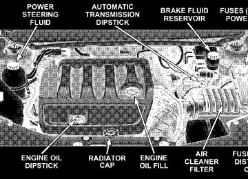
delay time. The delay can be regulated from a maximum of approximately 18 seconds between cycles, to a cycle every second. NOTE: The wiper delay times depend on vehicle speed. If the vehicle is moving less than 10 mph (16 km/h), delay times will be doubled. If the front wiper is operating when the ignition NOTE: is turned off, the wiper will automatically return to the ⬙Park⬙ position. When the vehicle is restarted, the wipers will resume operation. Adding Washer Fluid The fluid reservoir for the windshield washers is located in the engine compartment and should be checked for fluid level at regular intervals. Fill the reservoir with windshield washer solvent (not radiator antifreeze) and operate the system for a few seconds to flush out the residual water. Refer to the appropriate engine diagram (Section 7 “Maintaining Your Vehicle”) for the location of the reservoir.
112 UNDERSTANDING THE FEATURES OF YOUR VEHICLE
TILT/TELESCOPING STEERING COLUMN This feature allows you to tilt the steering column upward or downward. It also allows you to lengthen or shorten the steering column. The tilt/telescoping control handle is located below the steering wheel at the end of the steering column.
outward or push it inward as desired. To lock the steering column in position, push the control handle inward until fully engaged.
WARNING!
Do not adjust the steering wheel while driving. The telescoping adjustment must be locked while driv- ing. Adjusting the steering wheel while driving or driving without the telescoping adjustment locked could cause the driver to lose control of the vehicle.
Tilt / Telescoping Steering Wheel Lock
To unlock the steering column, pull the control handle outward. To tilt the steering column, move the steering wheel upward or downward as desired. To lengthen or shorten the steering column, pull the steering wheel
ELECTRONIC SPEED CONTROL — IF EQUIPPED When engaged, this device takes over the accelerator operation at speeds greater than 25 mph (40 km/h). The speed control lever is located on the right side of the steering wheel.
Speed Control Location
To Activate: Push the ON/OFF button located in the end of the Electronic Speed Control Lever. The CRUISE indicator in the instrument cluster will illuminate. To turn the system
UNDERSTANDING THE FEATURES OF YOUR VEHICLE 113
OFF, push the ON/OFF button a second time. The CRUISE indicator will turn off. The system should be turned OFF when not in use. NOTE: The Electronic Speed Control System will auto- matically turn itself off when the ignition key is turned to the “OFF” position.
WARNING!
Leaving the Electronic Speed Control system on when not in use is dangerous. You could accidentally set the system or cause it to go faster than you want. You could lose control and have an accident. Always leave the system OFF when you are not using it.
To Set At A Desired Speed: When the vehicle has reached the desired speed, press down on the lever and release. Release the accelerator and the vehicle will operate at the selected speed. NOTE: • The vehicle must be traveling at least 25 mph (40
km/h) for the speed control to set.
114 UNDERSTANDING THE FEATURES OF YOUR VEHICLE
• The vehicle should be traveling at a steady speed and
on level ground before pressing the SET lever.
To Deactivate: A soft tap on the brake pedal, pulling the speed control lever towards you “CANCEL”, or normal brake pressure while slowing the vehicle will deactivate speed control without erasing the set speed memory. Pressing the ON/OFF button or turning off the ignition switch erases the set speed memory. To Resume Speed: To resume a previously set speed, push the “RESUME ACCEL” lever up and release. Resume can be used at any speed above 20 mph (32 km/h). To Vary The Speed Setting: When the speed control is ON, speed can be increased by pushing up and holding “RESUME ACCEL”. Release the lever when the desired speed is reached, and the new speed will be set.
Tapping “RESUME ACCEL” once will result in a 1 mph (2 km/h) speed increase. Each time the lever is tapped, speed increases so that tapping the lever three times will increase speed by 3 mph (5 km/h), etc. To decrease speed while speed control is ON, push down and hold “SET DECEL”. Release the lever when the desired speed is reached, and the new speed will be set. Tapping the “SET DECEL” button once will result in a 1
mph (2 km/h) speed decrease. Each time the button is tapped, speed decreases.WARNING!
Speed Control can be dangerous where the system can’t maintain a constant speed. Your vehicle could go too fast for the conditions, and you could lose control. An accident could be the result. Don’t use Speed Control in heavy traffic or on roads that are winding, icy, snow-covered, or slippery.
To Accelerate For Passing: Depress the accelerator as you would normally. When the pedal is released, the vehicle will return to the set speed. Using Speed Control On Hills NOTE: The speed control system maintains speed up and down hills. A slight speed change on moderate hills is normal. On steep hills, a greater speed loss or gain may occur so it may be preferable to drive without speed control.
GARAGE DOOR OPENER (HomeLink姞) — IF EQUIPPED The HomeLink威 Universal Transceiver replaces up to three remote controls (hand held transmitters) that oper- ate devices such as garage door openers, motorized gates, or home lighting. It triggers these devices at the push of a button. The Universal Transceiver operates off your vehicle’s battery and charging system; no batteries are needed. NOTE: The HomeLink威 Universal Transceiver is dis- abled when the Vehicle Security Alarm is active.
UNDERSTANDING THE FEATURES OF YOUR VEHICLE 115
For additional information on HomeLink威, call 1–800– 355–3515, or on the internet at www.homelink.com.
The three buttons for your garage door opener will be located in the driver’s sunvisor. The training procedure is the same regardless of the 3-button location. Programming The Universal Transceiver (HomeLink姞)
NOTE: When programming a garage door opener, it is advised to park outside the garage and with the engine off. It is also recommended that you install a new battery
116 UNDERSTANDING THE FEATURES OF YOUR VEHICLE
in the hand-held transmitter of the device being pro- grammed. This will allow for quicker training and accu- rate transmission of the radio-frequency signal. If your garage door opener (located in the garage) is equipped with an antenna, make sure that the antenna is hanging straight down. 1. Erase the factory test codes by pressing the two outside buttons. Release the buttons when the light in the Universal Transceiver begins to flash (about 20 seconds). NOTE: Step 1 above does not have to be followed to program additional hand held transmitters. 2. Choose one of the three Universal Transceiver buttons to program. Position the end of your hand-held transmit- ter 1-3 inches (3-8 cm) away from the HomeLink buttons while keeping its indicator light in view.
Proper Transceiver Training Distance
3. Simultaneously press and hold the HomeLink button (that you want to train) and the hand-held transmitter button. Do not release the buttons until Step 4 is complete. NOTE: Some gate operators and garage door openers may require you to replace this Programming Step 3 with procedures noted under ⬙Gate Operator/Canadian Pro- gramming.⬙
4. The indicator light in the Universal Transceiver will begin to flash, first slowly and then rapidly. The rapid flashing indicates successful programming. If after 90
seconds the indicator light does not flash rapidly or goes out, return to step 1 and repeat the procedure. To train the other buttons, repeat steps 3 and 4. Be sure to keep your hand held transmitters in case you need to retrain the Universal Transceiver. NOTE: To program the remaining two HomeLink but- tons, begin with ⬙Programming⬙ Step Two. Do not repeat Step One.If your garage door opener fails to respond to NOTE: the programmed HomeLink威 Universal Transceiver, and your garage door opener is manufactured after 1995, it may have a multiple security code system (rolling code system). If your garage door opener is the “rolling code” type, please proceed to the heading “Programming A Rolling Code System.”
UNDERSTANDING THE FEATURES OF YOUR VEHICLE 117
Programming A “Rolling Code” System On garage door openers with the “Rolling Code” feature, the transmitter code changes after each use to prevent the copying of your code. NOTE: The assistance of a second person may make the following programming procedure quicker and easier. 1. Locate the training button on the garage door motor head unit. The exact location and color of the button may vary by garage door opener manufacturer. If you have difficulty in locating the training button, check your garage door opener manual, or call 1-800-355-3515 or, on the Internet, at www.homelink.com. 2. Press and hold the training button on the garage door opener head unit. This will activate the “training” light. NOTE: After completing step 2, you have 30 seconds to start step 3. 3. Return to the Universal Transceiver in the vehicle and firmly press and release the garage door button. Press and release the button a second time to complete the
118 UNDERSTANDING THE FEATURES OF YOUR VEHICLE
training process. Some garage door openers may require you to do this procedure a third time to complete the training. Canadian Programming/Gate Programming Canadian radio-frequency laws require transmitter sig- nals to ⬙time-out⬙ (or quit) after several seconds of transmission, which may not be long enough for HomeLink to pick up the signal during programming. Similar to this Canadian law, some U.S. gate operators are designed to ⬙time-out⬙ in the same manner. If you live in Canada or you are having difficulties programming a gate operator by using the ⬙Program- ming⬙ procedures (regardless of where you live), replace ⴖProgramming HomeLinkⴖ Step 3 with the following: 3. Continue to press and hold the HomeLink button while you press and release your hand-held transmitter every two seconds until the frequency signal is accepted successfully by HomeLink. The Universal Transceiver light will flash slowly and then rapidly when the pro- gramming is successful. Proceed with ⴖProgramming HomeLinkⴖ Step 4 to complete the procedure.
NOTE: When programming such a garage door opener or gate, unplug the device to prevent possible damage to the garage door or gate motor. Using HomeLink To operate, simply press and release the programmed HomeLink button. Activation will now occur for the trained device (i.e. garage door opener, gate operator, security system, entry door lock, home/office lighting, etc.). The light in the display shows that the signal is being transmitted. For convenience, the hand-held trans- mitter of the device may also be used at any time. Erasing HomeLink Buttons To erase programming from the three buttons (individual buttons cannot be erased but can be ⬙reprogrammed⬙ - note below), follow the step noted: Press and hold the two outer HomeLink buttons (for approximately 20 seconds). Release the buttons when the indicator begins to flash rapidly. All three channels will be cleared.
Reprogramming a Single HomeLink Button To program a device with a previously trained HomeLink button, follow these steps: 1. Press and hold the Universal Transceiver button to be reprogrammed. Do not release until step 4 has been completed. 2. When the indicator light begins to flash slowly (after 20 seconds), position the hand held transmitter one to three inches away from the button to be trained. 3. Press and hold the hand held transmitter button. 4. The Universal Transceiver indicator light will begin to flash, first slowly, then rapidly. When the indicator lights
UNDERSTANDING THE FEATURES OF YOUR VEHICLE 119
begin to flash rapidly, release both buttons. Security If you sell your vehicle, be sure to erase the frequencies by following the “Erasing HomeLink Buttons” instruc- tions in this section. This device complies with part 15 of FCC rules and with RSS-210 of Industry Canada. Operation is subject to the following conditions: • This device may not cause harmful interference. • This device must accept any interference that may be received including interference that may cause undes- ired operation.
120 UNDERSTANDING THE FEATURES OF YOUR VEHICLE
WARNING!
• A moving garage door can cause injury to people and pets in the path of the door. People or pets could be seriously or fatally injured. Only use this transceiver with a garage door opener that has a “stop and reverse” feature as required by federal safety standards. This includes most garage door opener models manufactured after 1982. Do not use a garage door opener without these safety features, it could cause injury or death. Call toll- free 1–800–355–3515 or, on the Internet at www.homelink.com for safety information or as- sistance. • Vehicle exhaust contains carbon monoxide, a dan- gerous gas. Do not run the vehicle’s exhaust while training the transceiver. Exhaust gas can cause serious injury or death.
NOTE: Changes or modifications not expressly ap- proved by the party responsible for compliance could void the user’s authority to operate the equipment.
HomeLink威 is a trademark owned by Johnson Controls, Inc. In the event that you are still having programming difficulties, questions, or comments, call toll free 1–800– 355–3515 or if you have access on the Internet, at www.homelink.com for information or assistance.
WARNING!
Your motorized door or gate will open and close while you are training the Universal Transceiver. Do not train the transceiver if people or pets are in the path of the door or gate. A moving door or gate can cause serious injury or death to people and pets or damage to objects.
POWER SUNROOF — IF EQUIPPED The sunroof controls are mounted between the sun visors in the Dome / Reading Lamp.
Power Sunroof Switch
UNDERSTANDING THE FEATURES OF YOUR VEHICLE 121
WARNING!
• Never leave children in a vehicle, with the keys in the ignition switch. Occupants, particularly unat- tended children, can become entrapped by the power sunroof while operating the power sunroof switch. Such entrapment may result in serious injury or death. • In an accident, there is greater risk of being thrown from a vehicle with an open sunroof. You could also be seriously injured or killed. Always fasten your seat belt properly and make sure all passengers are properly secured too. • Do not allow small children to operate the sun- roof. Never allow fingers or other body parts, or any object to project through the sunroof opening. Injury may result.
122 UNDERSTANDING THE FEATURES OF YOUR VEHICLE
Opening Sunroof - Manual Press the switch rearward and hold, and the sunroof will open automatically from any position. The sunroof will open fully, then stop automatically. During this opera- tion, any release of the sunroof switch will stop the sunroof. Opening Sunroof - Express Press the switch rearward and release, and the sunroof will open automatically from any position. The sunroof will open fully, then stop automatically. This is called Express Open. During Express Open operation, any movement of the sunroof switch will stop the sunroof. Closing Sunroof - Manual To Close the sunroof from an open or vent position, press and hold the switch forward. The sunroof will close fully and stop automatically. Release the switch to stop sun- roof travel at any point. Venting Sunroof - Express Press and release the ⬙V⬙ button, and the sunroof will open to the vent position. This is called Express Vent.
Closing Sunroof - Express Press the switch forward and release, and the sunroof will close automatically from any position. The sunroof will close fully, then stop automatically. This is called Express Close. During Express Close operation, any movement of the sunroof switch will stop the sunroof. Auto Sunroof (Express) with Anti–Pinch Protection — If Equipped During express closing, anytime an obstacle that restricts glass movement is detected, the motor will stop and reverse travel to avoid pinching the object.
WARNING!
There is no anti-pinch protection when the sunroof is almost closed. To avoid personal injury, be sure to clear your arms, hands, fingers and all objects from the sunroof path before closing.
UNDERSTANDING THE FEATURES OF YOUR VEHICLE 123
Ignition Off Operation For vehicles not equipped with the Electronic Vehicle Information Center (EVIC), the power sunroof switch will remain active for 10 minutes after the ignition switch is turned off. Opening either front door will cancel this feature. For vehicles equipped with the EVIC, the power sunroof switch will remain active for up to 60 minutes after the ignition switch is turned off. Opening either front door will cancel this feature. The time is programmable. For details, refer to “Delay Power Off to Accessories Until Exit,” under “Personal Settings (Customer Program- mable Features),” under “Electronic Vehicle Information Center (EVIC)” in Section 4 of this manual.
Sunshade Operation The sunshade can be opened manually. However, the sunshade will open automatically as the sunroof opens. NOTE: The sunshade cannot be closed if the sunroof is open. Wind Buffeting Wind buffeting can be described as the perception of pressure on the ears or a helicopter type sound in the ears. Your vehicle may exhibit wind buffeting with the windows down, or the sunroof (if so equipped) in certain open or partially open positions. This is a normal occur- rence and can be minimized. If the buffeting occurs with the rear windows open, then open the front and rear windows together to minimize the buffeting. If the buffeting occurs with the sunroof open, adjust the sun- roof opening to minimize the buffeting. Sunroof Maintenance Use only a non abrasive cleaner and a soft cloth to clean the glass panel.
124 UNDERSTANDING THE FEATURES OF YOUR VEHICLE
ELECTRICAL POWER OUTLETS There are two 12-volt electrical outlets on this vehicle. Both of the outlets are protected by a fuse. The 12-volt power outlet next to the ash receiver tray (if equipped with an optional Smoker’s Package) has power available only when the ignition is on. This outlet will also operate a conventional cigar lighter unit. If desired, the power outlet next to the ash NOTE: receiver tray (if equipped) can be converted by your authorized dealer to provide power with the ignition switch in the LOCK position.
Instrument Panel Power Outlet
The center console outlet is powered directly from the battery (power available at all times). Items plugged into this outlet may discharge the battery and/or prevent engine starting.
UNDERSTANDING THE FEATURES OF YOUR VEHICLE 125
NOTE: Due to built-in overload protection, the inverter will shut down if the power rating is exceeded.
WARNING!
To Avoid Serious Injury or Death: • Do not use a 3-Prong Adaptor. • Do not insert any objects into the receptacles. • Do not touch with wet hands. • Close the lid when not in use. • If this outlet is mishandled, it may cause an
electric shock and failure.
Console Interior
ELECTRICAL POWER INVERTER — IF EQUIPPED There is a 115 VAC (150-Watts Maximum) outlet in the cen- ter console for added conve- nience. This outlet can power cell phones, electronics, and other low power devices.
126 UNDERSTANDING THE FEATURES OF YOUR VEHICLE
Electrical Outlet Use With Engine Off
CAUTION!
• Many accessories that can be plugged in draw power from the vehicle’s battery, even when not in use (i.e. cellular phones, etc.). Eventually, if plugged in long enough, the vehicle’s battery will discharge sufficiently to degrade battery life and/or prevent engine starting. • Accessories that draw higher power (i.e. coolers, vacuum cleaners, lights, etc.) will degrade the battery even more quickly. Only use these inter- mittently and with greater caution. • After the use of high power draw accessories, or long periods of the vehicle not being started (with accessories still plugged in), the vehicle must be driven a sufficient length of time to allow the generator to recharge the vehicle’s battery.
CIGAR LIGHTER AND ASH RECEIVER The covered ash receiver is located in the instrument panel below the climate control knobs. The cigar lighter is located to the right of the ash receiver. As a child safety precaution, the lighter only operates with the ignition switch ON. It heats when pushed in and pops out automatically when ready for use. To preserve the heating element, do not hold the lighter in the heating position. Cup Holder Ash Receiver — If Equipped Should your vehicle not come equipped with the instru- ment panel cigar lighter and ash receiver, an optional ash receiver is available from your authorized dealer and will fit in either one of the center console cup holders.
UNDERSTANDING THE FEATURES OF YOUR VEHICLE 127
CAUTION!
If your vehicle is equipped with the heated and cooled cup holder, locate the cup holder ash receiver in the forward cup holder.
The optional ash receiver also comes with a cigar lighter. You may use the power outlet, located in the instrument panel below the climate control knob, or in the bottom of the console compartment, for this cigar lighter.
Optional Cup Holder Ash Receiver
128 UNDERSTANDING THE FEATURES OF YOUR VEHICLE
CONSOLE FEATURES
Console Features The center console armrest slides forward from design position to provide added user comfort. Two cup holders, each of which can accommodate large sized fast food beverage containers. A one piece cup holder insert for both cavities can easily be removed for cleaning. The cup holders will also accommodate large size cups and 20 oz. bottles. (An optional removable ashtray may be located in the one cup holder.)
Dual Storage Bins Lifting a latch at the front of the hinged armrest provides access to these storage areas.
1 — Release button for top compartment 2 — Release button for bottom compartment 3 — Top Compartment 4 — Bottom Compartment
• The Left Latch opens to the top storage area.
Console Features
UNDERSTANDING THE FEATURES OF YOUR VEHICLE 129
Video Console — If Equipped The optional VES™(Video Entertainment System) in- cludes the following components: • The screen for a rear seat DVD player is stored under • Remote Control • Audio / Video RCA Jacks
the armrest.
• The lower bin can be accessed directly, without first exposing the upper bin, by operating the right latch with the armrest down. • The first storage bin can be used to hold smaller items. • The lower storage bin includes a molded-in coin holder, room for CD’s, DVD’s, and a power outlet that allows a cell phone to recharge while concealed.
NOTE: A notch in the side of the console base under the armrest will also allow use of cell phone while still plugged into the power outlet and with the armrest latched down. NOTE: The power outlet located inside the console can also energize the cigar lighter in the available Smoker’s Package.
Video Console
130 UNDERSTANDING THE FEATURES OF YOUR VEHICLE
CUP HOLDERS
Heated or Cooled Cup Holder — If Equipped With this feature the rear cavity of the cup holder can heat or cool the beverage container it is holding. The rear cup holder can heat from room temperature (70°F /21°C), to 140°F (60°C) or cool it to near freezing, 0°F (–20°C). The switch is located on the front of the center console and has three positions: HEAT, OFF, COOL. When the unit is on and the LED is Red, the cup holder is being heated. When the LED is Blue, the cup holder is being cooled.
Cooled or Heated Cup Holder
A special mug is included with this feature and is specially designed to work best with this system.
Rear Bottle Holders There are built-in bottle holders located in both rear door trim panels.
UNDERSTANDING THE FEATURES OF YOUR VEHICLE 131
WARNING!
If containers of hot liquid are placed in the bottle holder, they can spill when the door is closed, burning the occupants. Be careful when closing the doors to avoid injury.
Rear Bottle Holder
UNDERSTANDING YOUR INSTRUMENT PANEL
CONTENTS
䡵 Instrument Panel Features . . . . . . . . . . . . . . . 136
䡵 Instrument Cluster—Base . . . . . . . . . . . . . . . . 137
䡵 Instrument Cluster—Premium . . . . . . . . . . . . 138
䡵 Instrument Cluster Descriptions . . . . . . . . . . . 139
䡵 Electronic Vehicle Information Center(EVIC) – If Equipped . . . . . . . . . . . . . . . . . . . 147
▫ Electronic Vehicle Information Center(EVIC) Displays . . . . . . . . . . . . . . . . . . . . . . 147
▫ EVIC Functions . . . . . . . . . . . . . . . . . . . . . . . 148
▫ Trip Functions . . . . . . . . . . . . . . . . . . . . . . . 149
▫ To Reset The Display . . . . . . . . . . . . . . . . . . . 150
▫ Compass Display . . . . . . . . . . . . . . . . . . . . . 150▫ Telephone — If Equipped . . . . . . . . . . . . . . . 153
▫ Navigation — If Equipped . . . . . . . . . . . . . . . 154
▫ Personal Settings(Customer Programmable Features)
. . . . . . . . 155
䡵 Setting The Analog Clock . . . . . . . . . . . . . . . . 157
䡵 Electronic Digital Clock . . . . . . . . . . . . . . . . . 158
▫ Clock Setting Procedure . . . . . . . . . . . . . . . . . 158
䡵 Radio General Information . . . . . . . . . . . . . . . 158
▫ Radio Broadcast Signals . . . . . . . . . . . . . . . . . 158
▫ Two Types Of Signals . . . . . . . . . . . . . . . . . . 158
▫ Electrical Disturbances . . . . . . . . . . . . . . . . . . 159
▫ AM Reception . . . . . . . . . . . . . . . . . . . . . . . 159134 UNDERSTANDING YOUR INSTRUMENT PANEL
▫ FM Reception . . . . . . . . . . . . . . . . . . . . . . . . 159
䡵 Sales Code REQ — AM/FM Stereo Radio
And 6–Disc CD/DVD Changer (MP3/WMA Aux Jack) . . . . . . . . . . . . . . . . . . 159
▫ Operating Instructions - Radio Mode . . . . . . . 160
▫ Operation Instructions -(Disc Mode For CD And MP3/WMA Audio Play, DVD-Video)
. . . . . . . . . . . . . . . . 166
▫ Notes On Playing MP3/WMA Files . . . . . . . . 168
▫ List Button(Disc Mode For MP3/WMA Play) . . . . . . . . . . 170
▫ Info Button
(Disc Mode For MP3/WMA Play) . . . . . . . . . . 170
䡵 Sales Code RES — AM/FM Stereo Radio
With CD Player (MP3 Aux Jack) . . . . . . . . . . . 172
▫ Operating Instructions - Radio Mode . . . . . . . 172
▫ Operation Instructions - CD Mode ForCD And MP3 Audio Play . . . . . . . . . . . . . . . 176
▫ Notes On Playing MP3 Files . . . . . . . . . . . . . 178
▫ List Button (CD Mode For MP3 Play) . . . . . . . 180
▫ Info Button (CD Mode For MP3 Play) . . . . . . . 180䡵 Sales Code RER — AM/FM/CD/DVD
Radio With Navigation System — If Equipped . . . . . . . . . . . . . . . . . . . . . . . . . . 181
▫ Operating Instructions — Satellite Radio . . . . . 182
▫ Clock Setting Procedure . . . . . . . . . . . . . . . . . 182
䡵 Satellite Radio — If Equipped . . . . . . . . . . . . . 183
▫ System Activation . . . . . . . . . . . . . . . . . . . . . 183
▫ Electronic Serial Number/Sirius IdentificationNumber (ENS/SID) . . . . . . . . . . . . . . . . . . . . 183
▫ Selecting Satellite Mode (RSC Radios) . . . . . . . 184
▫ Satellite Antenna . . . . . . . . . . . . . . . . . . . . . . 184
▫ Reception Quality . . . . . . . . . . . . . . . . . . . . . 184
▫ Operating Instructions - Satellite Mode . . . . . . 184▫ Operating Instructions -
Hands Free Phone (If Equipped)
. . . . . . . . . . 186
▫ Operating Instructions - Video Entertainment
System (VES®)威 (If Equipped) . . . . . . . . . . . . 186
䡵 Video Entertainment System —
If Equipped . . . . . . . . . . . . . . . . . . . . . . . . . . 187
䡵 Radio Operation And Cellular Phones . . . . . . . 188
䡵 Remote Sound System Controls —If Equipped . . . . . . . . . . . . . . . . . . . . . . . . . . 188
▫ Radio Operation . . . . . . . . . . . . . . . . . . . . . . 189UNDERSTANDING YOUR INSTRUMENT PANEL 135
▫ CD Player
. . . . . . . . . . . . . . . . . . . . . . . . . . 189
䡵 CD/DVD Disc Maintenance . . . . . . . . . . . . . . 189
䡵 Climate Controls . . . . . . . . . . . . . . . . . . . . . . 190▫ Manual Air Conditioning
And Heating System . . . . . . . . . . . . . . . . . . . 190
▫ Automatic Temperature Control (ATC)—
If Equipped . . . . . . . . . . . . . . . . . . . . . . . . . 194
▫ Operating Tips . . . . . . . . . . . . . . . . . . . . . . . 199
▫ Electric Rear Window Defroster . . . . . . . . . . . 202136 UNDERSTANDING YOUR INSTRUMENT PANEL
INSTRUMENT PANEL FEATURES
Instrument Panel
INSTRUMENT CLUSTER—BASE