- Download PDF Manual
-
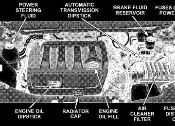
If your air conditioning performance seems NOTE: lower than expected, check the front of the A/C con- denser: located in front of the radiator, for an accumula- tion of dirt or insects. Clean with a gentle water spray from behind the radiator and through the condenser. Fabric front fascia protectors may reduce air flow to the condenser, reducing air conditioning performance.
192 UNDERSTANDING YOUR INSTRUMENT PANEL
Mode Control (Air Direction)
Mode control allows you to choose from several patterns of air distribution. You can select either a primary mode, as identified by the symbols, or a blend of two of these modes. The closer the control is to a particular mode, the more air distribution you re- ceive from that mode.
Air is directed through the outlets in the instrument panel. These outlets can be adjusted to direct air
Panel Mode
flow. Bi-Level Mode
Air is directed through the panel and floor outlets.
NOTE: There is a difference in temperature (in any conditions other than full cold or full hot), between the upper and lower outlets for added comfort. The warmer
air goes to the floor outlets. This feature gives improved comfort during sunny but cool conditions. Floor Mode
Air is directed through the floor outlets with a small amount through the defrost and side window
demist outlets. Mix Mode
Air is directed through the floor, defrost and side window demist outlets. This setting works best in cold or snowy conditions that require extra heat at the windshield. This setting is good for maintaining comfort while reducing moisture on the windshield. Defrost Mode
Air is directed through the windshield and side window demist outlets. Use this mode with maxi- mum blower and temperature settings for best wind- shield and side window defrosting. NOTE: The air conditioning compressor operates in Floor, Mix and Defrost, or a blend of these modes even if the Air Conditioning Snowflake button is not pressed.
This dehumidifies the air to help dry the windshield. To improve fuel economy, use these modes only when necessary. Recirculation Control
Use this button to choose be- tween outside air intake or recirculation of the air inside the vehicle. A lamp will illu- minate when you are in recir- culate mode. Only use the re- circulate mode to temporarily block out any outside odors, smoke, or dust and to cool the interior rapidly upon initial start up in very hot or humid weather.
NOTE: • Continuous use of the recirculation mode may make the inside air stuffy and window fogging may occur. Extended use of this mode is not recommended. • In cold or damp weather, the use of the recirculation mode will cause windows to fog on the inside because
UNDERSTANDING YOUR INSTRUMENT PANEL 193
of moisture build up inside the vehicle. For maximum defogging, select the Outside Air position. • In order to prevent fogging, when the recirculation button is press and the mode control is set to panel or panel / floor, the A/C will engage automatically. • The A/C can be deselected manually without disturb-
ing the mode control selection.
Air Outlets The airflow from each of the instrument panel outlets can be adjusted for direction and turned on or off to control air flow. NOTE: For maximum airflow to the rear, the center instrument panel outlets can be aimed, so that they are directed toward the rear seat passengers. Economy Mode If economy mode is desired, press the A/C button to turn off the indicator light, and the A/C compressor. Move the temperature control lever to the desired temperature.
194 UNDERSTANDING YOUR INSTRUMENT PANEL
Air Conditioning Operation
Use this button to engage the Air Conditioning. A lamp will illuminate when the Air Con- ditioning System is engaged
accomplish this, the system gathers information from the cabin infrared sensor mounted between the sun-visors and from various sensors located throughout the vehicle.
NOTE: The air conditioning compressor will not en- gage until the engine has been running for about 10
seconds. MAX A/C For maximum cooling use the A/C and recirculate but- tons at the same time. Automatic Temperature Control (ATC)— If Equipped The Infrared Climate Control System automatically maintains the climate in the cabin of the vehicle at the comfort levels desired by the driver and passenger. ToAutomatic Temperature Control
The controls on the climate control provide the system with operator input. Other sensors take account of ve- hicle speed, A/C pressure, outside temperature, and engine cooling temperature. Using all of these inputs, the system automatically adjusts airflow temperature, air- flow distribution, airflow volume, and the amount of outside air recirculation. This maintains a comfortable temperature even under changing conditions.
Operation of the system is quite simple. 1. Turn the Mode Control knob (on the right) and the Blower Control knob (on the left) to AUTO. NOTE: The AUTO position performs best for front seat occupants only. 2. Dial in the temperature you would like the system to maintain by rotating the Temperature Control knob. Once the comfort level is selected, the system will main- tain that level automatically using the heating system. Should the desired comfort level require air conditioning, the system will automatically make the adjustment. You will experience the greatest efficiency by simply allowing the system to function automatically. Selecting the OFF position on the blower control stops the system completely and closes the outside air intake. 72°F (22°C) is the recommended setting for maximum comfort for the average person; however, this may vary. NOTE: The temperature setting can be adjusted at any time without affecting automatic operation.
UNDERSTANDING YOUR INSTRUMENT PANEL 195
Automatic Blower Control
To engage the Automatic Temperature Control, turn the Blower Control Knob Indica- tor to AUTO.
Automatic Temperature Control
Use this control to regulate the temperature of the air in- side the passenger compart- ment. Rotate the outer ring to the desired numerical tem- perature.
196 UNDERSTANDING YOUR INSTRUMENT PANEL
Air conditioning in this system is automatic. Pressing the Air Conditioning Control button while in AUTO mode will cause the LED in the control button to flash three times and then turn off. This indicates that the system is in AUTO mode and request- ing the air conditioning is not necessary. If your air conditioning performance seems NOTE: lower than expected, check the front of the A/C con- denser: located in front of the radiator, for an accumula- tion of dirt or insects. Clean with a gentle water spray from behind the radiator and through the condenser. Fabric front fascia protectors may reduce air flow to the condenser, reducing air conditioning performance.
Automatic Mode Control (Air Direction)
To engage Automatic Tem- perature Control, turn the se- lector fully left to AUTO.
The system will automatically control recircu- lation. However, pressing the Recirculation Control button will temporarily put the system in recirculation mode (ten minutes). This can be used when outside conditions such as smoke, odors, dust, or high humidity are present. Activating recircula- tion will cause the LED in the control button to illumi- nate. After ten minutes, the system will return to normal AUTO mode function and the LED will turn off. NOTE: • When the ignition switch is turned OFF, the recircula-
tion feature will be cancelled.
• In cold weather, use of the Recirculation mode may lead to excessive window fogging. The Recirculation mode is not allowed in the Mix and Defrost modes to improve window clearing operation. Recirculation will be disabled automatically if these modes are selected. • Extended use of recirculation may cause the windows to fog. If the interior of the windows begins to fog, press the Recirculation button to return to outside air. Some temp/humidity conditions will cause captured interior air to condense on windows and hamper visibility. For this reason, the system will not allow Recirculation to be selected while in floor, defrost, or defrost/floor mode. Attempting to use the recircula- tion while in these modes will cause the LED in the control button to blink and then turn off. • Most of the time, when in Automatic Operation, you can temporarily put the system into Recirculation Mode by pressing the Recirculation Button. However, under certain conditions, while in Automatic Mode, the system is blowing air out the defrost vents. When
UNDERSTANDING YOUR INSTRUMENT PANEL 197
these conditions are present and the Recirculation Button is pressed the indicator will flash and remain off. This tells you that you are unable to go into recirculation mode at this time. If you would like to go into Recirculation Mode, you must first move your Mode Knob to Panel, Panel/Floor and then press the Recirculation Button. This feature will reduce the possibility of window fogging.
Manual Operation This system offers a full complement of manual override features, which consist of Blower Preferred Automatic, Mode Preferred Automatic, or Blower and Mode Pre- ferred Automatic. This means the operator can override the blower, the mode, or both. There is a manual blower range for times when the AUTO setting is not desired. The blower can be set to any fixed blower speed by rotating the Blower Control knob (on the left). NOTE: Please read the Automatic Temperature Control Operation Chart that follows for details.
198 UNDERSTANDING YOUR INSTRUMENT PANEL
Auto Climate Controls Chart
The operator can override the AUTO mode setting to change airflow distribution by rotating the Mode Control knob (on the right) to one of the following positions. Panel Mode
Air is directed through the outlets in the instrument panel. These outlets can be adjusted to direct air flow.
Bi-Level Mode
Air is directed through the panel and floor outlets.
NOTE: There is a difference in temperature (in any conditions other than full cold or full hot), between the upper and lower outlets for added comfort. The warmer air goes to the floor outlets. This feature gives improved comfort during sunny but cool conditions. Floor Mode
Air is directed through the floor outlets with a small amount through the defrost and side window
demist outlets. Mix Mode
Air is directed through the floor, defrost and side window demist outlets. This setting works best in cold or snowy conditions that require extra heat at
UNDERSTANDING YOUR INSTRUMENT PANEL 199
the windshield. This setting is good for maintaining comfort while reducing moisture on the windshield. Defrost Mode
Air is directed through the windshield and side window demist outlets. Use this mode with maxi- mum blower and temperature settings for best wind- shield and side window defrosting. Operating Tips NOTE: Refer to the chart at the end of this section for suggested control settings for various weather condi- tions. Summer Operation The engine cooling system in air-conditioned vehicles must be protected with a high-quality antifreeze coolant to provide proper corrosion protection and to protect against engine overheating. A 50% solution of ethylene glycol antifreeze coolant in water is recommended. Refer to “Maintenance Procedures” in Section 7 of this manual for proper coolant selection. Winter Operation Use of the air Recirculation mode during winter months is not recommended because it may cause window fogging.
200 UNDERSTANDING YOUR INSTRUMENT PANEL
Vacation Storage Anytime you store your vehicle, or keep it out of service (i.e. vacation) for two weeks or more, run the air condi- tioning system at idle for about five minutes in the fresh air and high blower setting. This will insure adequate system lubrication to minimize the possibility of com- pressor damage when the system is started again. Window Fogging Interior fogging on the windshield can be quickly re- moved by turning the mode selector to Defrost. The Defrost/Floor mode can be used to maintain a clear windshield and provide sufficient heating. If side win- dow fogging becomes a problem increase blower speed. Vehicle windows tend to fog on the inside in mild but rainy or humid weather. NOTE: Recirculate without A/C should not be used for long periods as fogging may occur. Side Window Demisters A side window demister outlet is at each end of the instrument panel. These nonadjustable outlets direct air toward the side windows when the system is in either the
FLOOR, MIX, or DEFROST mode. The air is directed at the area of the windows through which you view the outside mirrors. Outside Air Intake Make sure the air intake, located directly in front of the windshield, is free of obstructions such as leaves. Leaves collected in the air intake may reduce airflow, and if they enter the plenum, they could plug the water drains. In winter months, make sure the air intake is clear of ice, slush, and snow. A/C Air Filter — If Equipped An air filter is included in the optional Security Group. The filter will reduce, but not eliminate, diesel and agricultural smells. The filter acts on air coming from outside the vehicle and recirculated air within the pas- senger compartment. The filter’s normal service life is 12,000 miles (20,000 km) or one year. The air filter change schedule coincides with that for engine oil and filter. As with oil changes, the interval is shorter for heavy duty service or dusty conditions. See your authorized dealer for service.
Control Setting Suggestions for Various Weather Conditions
UNDERSTANDING YOUR INSTRUMENT PANEL 201
202 UNDERSTANDING YOUR INSTRUMENT PANEL
Electric Rear Window Defroster
Press this button, located on the Blower Control knob, to turn on the rear window defroster and the heated side mirrors — if equipped. A light in the button will illuminate to indicate the rear window defroster is ON. The defroster automatically turns off after about 10
minutes of operation.CAUTION!
To avoid damaging the electrical conductors of the rear window defroster, do not use scrapers, sharp instruments, chemically harsh or abrasive window cleaners on the interior surface of the window. Labels can be gently peeled off after soaking with warm water.
STARTING AND OPERATING
CONTENTS
䡵 Starting Procedures
. . . . . . . . . . . . . . . . . . . . 207
▫ Automatic Transaxle . . . . . . . . . . . . . . . . . . . 207
▫ Normal Starting . . . . . . . . . . . . . . . . . . . . . . 207
▫ Tip Start Feature — AutomaticTransaxle Only . . . . . . . . . . . . . . . . . . . . . . . 208
▫ Extremely Cold Weather
(Below ⫺20°F Or ⫺29°C) . . . . . . . . . . . . . . . . 208
▫ If Engine Fails To Start . . . . . . . . . . . . . . . . . 208
▫ After Starting . . . . . . . . . . . . . . . . . . . . . . . . 209
▫ Remote Start System — If Equipped . . . . . . . . 209
▫ How To Use Remote Start . . . . . . . . . . . . . . . 209
䡵 Automatic Transaxle . . . . . . . . . . . . . . . . . . . . 211▫ Brake/Transaxle Interlock System . . . . . . . . . . 212
▫ Automatic Transaxle IgnitionInterlock System . . . . . . . . . . . . . . . . . . . . . . 212
▫ Four Speed Or Six Speed (AutoStick)
Automatic Transaxle . . . . . . . . . . . . . . . . . . . 212
䡵 AutoStick威 — If Equipped . . . . . . . . . . . . . . . 214
▫ AutoStick威 Operation . . . . . . . . . . . . . . . . . . 215
▫ AutoStick威 General Information . . . . . . . . . . . 215
䡵 Parking Brake . . . . . . . . . . . . . . . . . . . . . . . . . 216
䡵 Brake System . . . . . . . . . . . . . . . . . . . . . . . . . 217▫ Anti-Lock Brake System (ABS) —
If Equipped . . . . . . . . . . . . . . . . . . . . . . . . . 218
204 STARTING AND OPERATING
䡵 Electronic Brake Control System –
ABS/TCS/BAS/ESP . . . . . . . . . . . . . . . . . . . . 221
▫ Anti-Lock Brake System (ABS) —If Equipped . . . . . . . . . . . . . . . . . . . . . . . . . 221
▫ Traction Control System (TCS) —
If Equipped . . . . . . . . . . . . . . . . . . . . . . . . . 221
▫ Brake Assist System (BAS) — If Equipped . . . . 221
▫ Electronic Stability Program (ESP) —If Equipped . . . . . . . . . . . . . . . . . . . . . . . . . 222
䡵 Power Steering . . . . . . . . . . . . . . . . . . . . . . . . 225
䡵 Driving On Slippery Surfaces . . . . . . . . . . . . . 226
▫ Acceleration . . . . . . . . . . . . . . . . . . . . . . . . . 226
▫ Traction . . . . . . . . . . . . . . . . . . . . . . . . . . . . 226
䡵 Tire Safety Information . . . . . . . . . . . . . . . . . . 227
▫ Tire Markings . . . . . . . . . . . . . . . . . . . . . . . . 227
▫ Tire Identification Number (TIN) . . . . . . . . . . 230
▫ Tire Loading And Tire Pressure . . . . . . . . . . . 231䡵 Tires — General Information . . . . . . . . . . . . . . 235
▫ Tire Pressure . . . . . . . . . . . . . . . . . . . . . . . . . 235
▫ Tire Inflation Pressures . . . . . . . . . . . . . . . . . 236
▫ Radial-Ply Tires . . . . . . . . . . . . . . . . . . . . . . 238
▫ Compact Spare Tire — If Equipped . . . . . . . . . 238
▫ Limited Use Spare — If Equipped . . . . . . . . . 239
▫ Tire Spinning . . . . . . . . . . . . . . . . . . . . . . . . 240
▫ Tread Wear Indicators . . . . . . . . . . . . . . . . . . 240
▫ Life Of Tire . . . . . . . . . . . . . . . . . . . . . . . . . 241
▫ Replacement Tires . . . . . . . . . . . . . . . . . . . . . 241
▫ Alignment And Balance . . . . . . . . . . . . . . . . . 242䡵 Tire Pressure Monitoring System (TPMS) —
If Equipped . . . . . . . . . . . . . . . . . . . . . . . . . . 243
▫ Base Tire Pressure Monitoring System(TPMS) Operation – If Equipped . . . . . . . . . . 243
▫ Premium System – If Equipped . . . . . . . . . . . 244▫ General Information . . . . . . . . . . . . . . . . . . . 248
䡵 Tire Chains . . . . . . . . . . . . . . . . . . . . . . . . . . . 248
䡵 Snow Tires . . . . . . . . . . . . . . . . . . . . . . . . . . . 248
䡵 Tire Rotation Recommendations . . . . . . . . . . . 249
䡵 Fuel Requirements . . . . . . . . . . . . . . . . . . . . . 250
▫ 2.4L And 2.7L Engines . . . . . . . . . . . . . . . . . . 250
▫ 3.5L Engine . . . . . . . . . . . . . . . . . . . . . . . . . 250
▫ Reformulated Gasoline . . . . . . . . . . . . . . . . . 251
▫ Gasoline/Oxygenate Blends . . . . . . . . . . . . . . 251
▫ MMT In Gasoline . . . . . . . . . . . . . . . . . . . . . 252
▫ Materials Added To Fuel . . . . . . . . . . . . . . . . 252
▫ Fuel System Cautions . . . . . . . . . . . . . . . . . . 252
▫ Carbon Monoxide Warnings . . . . . . . . . . . . . . 253䡵 Flexible Fuel— 2.7L Engines Only
(Except California) . . . . . . . . . . . . . . . . . . . . . 253
▫ E-85 General Information . . . . . . . . . . . . . . . . 253STARTING AND OPERATING 205
▫ Ethanol Fuel (E-85) . . . . . . . . . . . . . . . . . . . . 254
▫ Fuel Requirements . . . . . . . . . . . . . . . . . . . . 254
▫ Selection Of Engine Oil For Flexible FuelVehicles (E-85) And Gasoline Vehicles . . . . . . . 255
▫ Starting . . . . . . . . . . . . . . . . . . . . . . . . . . . . 255
▫ Cruising Range . . . . . . . . . . . . . . . . . . . . . . . 255
▫ Replacement Parts . . . . . . . . . . . . . . . . . . . . . 255
▫ Maintenance . . . . . . . . . . . . . . . . . . . . . . . . . 255
䡵 Adding Fuel . . . . . . . . . . . . . . . . . . . . . . . . . . 256
▫ Fuel Filler Cap (Gas Cap) . . . . . . . . . . . . . . . 256
▫ Loose Fuel Filler Cap Message . . . . . . . . . . . . 257
䡵 Vehicle Loading . . . . . . . . . . . . . . . . . . . . . . . 258
▫ Vehicle Certification Label . . . . . . . . . . . . . . . 258
▫ Gross Vehicle Weight Rating (GVWR) . . . . . . . 259
▫ Gross Axle Weight Rating (GAWR) . . . . . . . . . 259
▫ Overloading . . . . . . . . . . . . . . . . . . . . . . . . . 259206 STARTING AND OPERATING
▫ Loading . . . . . . . . . . . . . . . . . . . . . . . . . . . . 260
䡵 Trailer Towing . . . . . . . . . . . . . . . . . . . . . . . . 261
▫ Common Towing Definitions . . . . . . . . . . . . . 261
▫ Trailer Hitch Classification . . . . . . . . . . . . . . . 263
▫ Trailer Towing Weights (Maximum TrailerWeight Ratings)
▫ Trailer And Tongue Weight
. . . . . . . . . . . . . . . . . . . . . . 263
. . . . . . . . . . . . . . 264▫ Towing Requirements . . . . . . . . . . . . . . . . . . 265
▫ Towing Tips . . . . . . . . . . . . . . . . . . . . . . . . . 269䡵 Recreational Towing
(Behind Motorhome, Etc.) . . . . . . . . . . . . . . . . 270
▫ Towing This Vehicle Behind AnotherVehicle (Flat Towing With All Four Wheels On The Ground) . . . . . . . . . . . . . . . . . . . . . . 270
STARTING PROCEDURES Before starting your vehicle, adjust your seat, adjust both inside and outside mirrors, and fasten your seat belt. Make sure all occupants have securely fastened their seat belts.
WARNING!
Never leave children alone in a vehicle. Leaving children in a vehicle unattended is dangerous for a number of reasons. A child or others could be seriously or fatally injured. Don’t leave the keys in the ignition. A child could operate power windows, other controls, or move the vehicle.
STARTING AND OPERATING 207
WARNING!
Be sure to turn off the engine if you want to rest or sleep in your car. Accidents can be caused by inad- vertently moving the gear selection lever or by pressing the accelerator pedal. This may cause exces- sive heat in the exhaust system, resulting in over- heating and vehicle fire which may cause serious or fatal injuries.
Automatic Transaxle The gear selector must be in the PARK or NEUTRAL position before you can start the engine. Apply the brakes before shifting to any driving gear. NOTE: You must press the brake pedal before shifting out of Park. Normal Starting Normal Starting of either a cold or a warm engine does not require pumping or depressing the accelerator pedal. Simply turn the ignition switch to the “START” position and release when the engine starts. If the engine fails to
208 STARTING AND OPERATING
start within 15 seconds, turn the ignition switch to the “OFF” position, wait 10 to 15 seconds, then repeat the normal starting procedure.
WARNING!
Do not attempt to push or tow your vehicle to get it started. Vehicles equipped with an automatic trans- axle cannot be started this way. Unburned fuel could enter the catalytic converter and once the engine has started, ignite and damage the converter and vehicle. If the vehicle has a discharged battery, booster cables may be used to obtain a start from another vehicle. This type of start can be dangerous if done improp- erly, so follow the procedure carefully. See section 6
of this manual for jump starting instructions.Tip Start Feature — Automatic Transaxle Only
Do not press the accelerator. Turn the ignition key briefly to START position, and release it. The starter motor will continue to run, but will automatically disengage itself when the engine is running.
Ignition Key Position
Extremely Cold Weather (below ⫺20°F or ⫺29°C) To insure reliable starting at these temperatures, use of an externally powered electric engine block heater (available from your dealer) is recommended. If Engine Fails to Start If the engine fails to start after you have followed the “NORMAL STARTING” procedure, it may be flooded. Push the accelerator pedal all the way to the floor and hold it there. Crank the engine for no more than 15
seconds. This should clear any excess fuel in case theengine is flooded. Leave the ignition key in the ON position, release the accelerator pedal and repeat the “NORMAL STARTING” procedure.
WARNING!
Never pour fuel or other flammable liquid into the throttle body air inlet opening in an attempt to start the vehicle. This could result in flash fire causing serious personal injury.
CAUTION!
To prevent damage to the starter, do not crank the engine for more than 15 seconds at a time. Wait 10 to 15 seconds before trying again.
STARTING AND OPERATING 209
After Starting The idle speed will automatically decrease as the engine warms up. Remote Start System — If Equipped Remote start conveniently starts the engine from outside the vehicle by using the Remote Keyless Entry (RKE) key fob while maintaining security. The system has a targeted range of 328 ft. (100 m). The vehicle must be locked, the deck lid and hood closed and the transmission in Park in order to start the engine using the Remote Start button on the key fob. NOTE: Remote start requires Automatic Transaxle equipped vehicles. How To Use Remote Start To enter the Remote Start mode , depress the Remote Start button twice on the key fob. The engine will start and the vehicle will remain in the remote start mode for a 15 minute cycle.
210 STARTING AND OPERATING
REMOTE START BUTTON
To exit the Remote Start mode , allow the engine to run the cycle or depress the unlock button to disarm the Vehicle Theft Security Alarm and within one minute insert the key into the ignition and turn the ignition to the RUN position. The ignition must be in the RUN position in order to drive the vehicle. NOTE: The engine can be started two consecutive times (two 15 minute cycles) by using the key fob. For a third
cycle, the key must be cycled to the ignition RUN position and then repeat the start sequence. To shut off the vehicle when it is in Remote Start mode, press the remote start button once. In order to avoid inadvertent shut downs, the one-time press to shut down the vehicle will be disabled for two seconds after receipt of a valid remote start request. NOTE: When the vehicle is in the Remote Start mode, power window and sunroof operation are disabled for security. The following conditions must be met before the engine will remote start: • Automatic Transaxle in Park • All doors are closed • Hood is closed • Hazard Switch is off • Brake Switch is inactive • Key is not in the ignition • Battery is at an acceptable charge level • Panic button on key fob is not depressed
AUTOMATIC TRANSAXLE
STARTING AND OPERATING 211
• Shift into or out of REVERSE only after the vehicle has come to a complete stop and the engine is at idle speed. • Do not shift from REVERSE, PARK, or NEUTRAL into any forward gear when the engine is above idle speed. • Before shifting into any gear, make sure your foot is
firmly on the brake pedal.
Automatic Transaxle Shifter
CAUTION!
Damage to the transaxle may occur if the following precautions are not observed: • Shift into PARK only after the vehicle has come to a
complete stop.
NOTE: You MUST press and hold the brake pedal down while shifting out of Park.
WARNING!
It is dangerous to shift the selector lever out of “P” or “N” if the engine speed is higher than idle speed. If your foot is not firmly on the brake pedal, the vehicle could accelerate quickly forward or in re- verse. You could lose control of the vehicle and hit someone or something. Only shift into gear when the engine is idling normally and when your right foot is firmly on the brake pedal.
212 STARTING AND OPERATING
Brake/Transaxle Interlock System This system prevents you from moving the gear shift out of Park and into any gear unless the brake pedal is pressed. This system is active only while the ignition switch is in the ON or ACC positions. Always depress the brake pedal first, before moving the gear selector out of PARK. If a malfunction occurs, the transaxle will not NOTE: shift out of park. Battery power is required to release the brake/transaxle interlock system. There is an override system that allows you to shift out of Park in case of loss of power. To activate the override system, remove the cup holder liner, insert a key, screwdriver or finger into the front hole and push the lever forward. If this occurs obtain service as soon as possible. Automatic Transaxle Ignition Interlock System This system prevents the key from being removed unless the shift lever is in PARK. It also prevents shifting out of PARK unless the key is in the OFF or ON positions. If a malfunction occurs, the system will trap the NOTE: key in the ignition cylinder to warn you that this safety
feature is inoperable. The engine can be started and stopped but the key cannot be removed until you obtain service. Four Speed or Six Speed (AutoStick) Automatic Transaxle The electronically controlled transaxle provides a precise shift schedule. The transaxle electronics are self- calibrating; therefore, the first few shifts on a new vehicle, may be somewhat abrupt. This is a normal condition, and precision shifts will develop within a few hundred miles. Reset Mode - Electronic Transaxle The transaxle is monitored electronically for abnormal conditions. If a condition is detected that could cause damage, the transaxle automatically shifts into second gear. The transaxle remains in second gear (3rd gear with six speed automatic) despite the forward gear selected. Park (P), Reverse (R), and Neutral (N) will continue to operate. This Reset feature allows the vehicle to be driven to a dealer for service without damaging the transaxle. In the event that the problem has been momentary, the transaxle can be reset to regain all forward gears.
• Stop the vehicle and shift into Park (P). • Turn the key to OFF then restart the engine. • Shift into the desired range and resume driving. NOTE: Even if the transaxle can be reset, it is recom- mended that you visit a dealer at your earliest possible convenience. Your dealer has diagnostic equipment to determine if the problem could recur. If the transaxle cannot be reset, dealer service is required. Gear Ranges for Automatic Transaxle
“P” Park Supplements the parking brake by locking the transaxle. The engine can be started in this range. Never attempt to use PARK while vehicle is in motion. Apply parking brake when leaving vehicle in this range. DO NOT race the engine when shifting from PARK or NEUTRAL positions into another gear range.
STARTING AND OPERATING 213
WARNING!
Never use Park position on an Automatic Transaxle as a substitute for the parking brake. Always apply parking brake fully when parked to guard against vehicle movement and possible injury or damage.
“R” Reverse Shift into this range only after the vehicle has come to a complete stop. “N” Neutral Engine may be started in this range. “D” Overdrive For most city and highway driving, it provides smoothest upshifts and downshifts and best fuel economy. When frequent transaxle shifting occurs while using the “D” Overdrive position, such as when operating the vehicle under heavy loading conditions, (i.e. in hilly terrain, traveling into strong head winds or while towing heavy trailers), using the “3” position will improve performance and extend transaxle life by reducing excessive shifting and heat build-up.
214 STARTING AND OPERATING
“3” Drive This range eliminates shifts into Overdrive. The transaxle will operate normally in First, Second and Third while in this range. The “3” position should also be used when descending steep grades to prevent brake system dis- tress. NOTE: Using the “3” range while operating the vehicle under heavy operating conditions will improve perfor- mance and extend transaxle life by reducing excessive shifting and heat build up. “L” Low This range should be used for engine braking when descending very steep grades. In this range, upshifts will occur only to prevent engine overspeed while downshifts occur earlier than other gear range selections. NOTE: The vehicle computer will over ride Overdrive and “3” Drive ranges by changing shift points if the transaxle operating temperature exceeds acceptable lim- its. This is done to prevent transaxle damage due to overheating.
AUTOSTICK姞 — IF EQUIPPED AutoStick威 is a driver-interactive transaxle that offers six manual ratio changes to provide you with more control. AutoStick威 allows you to maximize engine braking, eliminate undesirable upshifts and downshifts, and im- prove overall vehicle performance. This system can also provide you with more control during passing, city driving, cold slippery conditions, mountain driving, trailer towing, and many other situations.
AutoStick威 Shift Lever
AutoStick姞 Operation By placing the selector lever one shift level below the ⬙D⬙ position, it can be moved from side to side. This allows the driver to select a higher or lower range of gears. Moving the selector lever to the Left (-) triggers a downshift and to the Right (+) an upshift. The gear position will display in the instrument cluster on the transaxle range indicator. In Autostick威 mode, the transaxle will only shift NOTE: up or down when the driver moves the selector lever to the Right (+) or Left (-). Holding the lever to (+) for at least one second, will deactivate AutoStick威. AutoStick威 is also deactivated when the lever is shifted out of the (+) or (-) and into ⬙D.⬙ AutoStick姞 General Information • You can start out in first or second gear. The system will ignore attempts to upshift at too low of a vehicle speed. • If a ratio other than 1st is selected and the vehicle is logic will
brought to a stop, the transaxle control automatically select the 1st gear ratio.
STARTING AND OPERATING 215
gaged.
conditions.
• Starting out in second gear is helpful in snowy or icy • Avoid using speed control when Autostick威 is en- • The transaxle will automatically shift up when maxi- mum engine speed is reached while Autostick威 is engaged. • transaxle shifting will be more noticeable when Auto- • If a low range is selected and the engine accelerates to the rev limit, the transaxle will automatically select the next higher ratio. • If a downshift would cause the engine to over-speed, that shift will not occur until it is safe for the engine. Mostly the transaxle will stay in the manually selected ratio, however.
stick威 is engaged.
• If the system detects powertrain overheating,
the transaxle will revert to the automatic shift mode and remain in that mode until the powertrain cools off.
216 STARTING AND OPERATING
• If the system detects a problem it will disable the AutoStick威 mode and the transaxle will return to the automatic mode until the problem is corrected.
PARKING BRAKE
When the parking brake is applied with the ignition on, the Brake Light in the instrument cluster will come on.
NOTE: This light, when illuminated with parking brake application, shows only that the parking brake is on. It does not show the degree of brake application. If the light remains on with the parking brake NOTE: released, a brake system malfunction is indicated. Have the brake system serviced by an authorized dealer im- mediately. If the parking brake is applied while the vehicle NOTE: is moving, a chime will sound to alert the driver. The chime will sound up to 10 times or until the vehicle has returned to a stop. Before leaving the vehicle, make sure that the parking brake is fully applied. For manual transaxle vehicles,
in REVERSE. For vehicles place the gear selector equipped with automatic transaxles, place the gear selec- tor in the PARK position. To release the parking brake, slightly pull up the handle while pushing the lock button, and guide the lever downward to its stop. The brake warning light in the instrument cluster should go out. NOTE: The parking brake lever will not release unless the lever is pulled up slightly past its applied position.
Parking Brake Lever
NOTE: When parking on a hill, it is important to set the parking brake before placing the gear selector in Park, otherwise the load on the automatic transaxle locking mechanism may make it difficult to move the selector out of Park. As an added precaution, turn the front wheels toward the curb on a downhill grade and away from the curb on a uphill grade. NOTE: You should always apply the parking brake before leaving the vehicle.
WARNING!
• Never leave children alone in a vehicle. Leaving children in a vehicle unattended is dangerous for a number of reasons. A child or others could be injured. Don’t leave the keys in the ignition. A child could operate power windows, other con- trols, or move the vehicle. • Be sure the parking brake is fully disengaged before driving. Failure to do so can lead to brake failure and an accident.
STARTING AND OPERATING 217
BRAKE SYSTEM Your vehicle is equipped with power assisted brakes as standard equipment. In the event power assist is lost for any reason (for example, repeated brake applications with the engine off), the brakes will still function. How- ever, the effort required to brake the vehicle will be much greater than that required with the power system oper- ating.
WARNING!
Riding the brakes can lead to brake failure and possibly an accident. Driving with your foot resting or riding on the brake pedal can result in abnormally high brake temperatures, excessive lining wear, and possible brake damage. You wouldn’t have your full braking capacity in an emergency.
218 STARTING AND OPERATING
If either of the two hydraulic systems lose normal capa- bility, the remaining system will still function with some loss of overall braking effectiveness. This will be evident by increased pedal travel during application and greater pedal force required to slow or stop. In addition, if the malfunction is caused by an internal leak, as the brake fluid in the master cylinder drops, the brake warning indicator will light.
WARNING!
Driving a vehicle with the brake light on is danger- ous. A significant decrease in braking performance or vehicle stability during braking may occur. It will take you longer to stop the vehicle or will make your vehicle harder to control. You could have an acci- dent. Have the vehicle checked immediately.
Anti-Lock Brake System (ABS) — If Equipped The Anti-Lock Brake System provides increased vehicle stability and brake performance under most braking conditions. The system automatically “pumps” the brakes during severe braking conditions to prevent wheel lock-up.
WARNING!
Pumping of the Anti-Lock Brakes will diminish their effectiveness and may lead to an accident. Pumping makes the stopping distance longer. Just press firmly on your brake pedal when you need to slow down or stop.
WARNING!
• Anti-lock system (ABS) cannot prevent the natu- ral laws of physics from acting on the vehicle, nor can it increase braking or steering efficiency be- yond that afforded by the condition of the vehicle brakes and tires or the traction afforded.
• The ABS cannot prevent accidents,
including those resulting from excessive speed in turns, following another vehicle too closely, or hydro- planing. Only a safe, attentive, and skillful driver can prevent accidents. • The capabilities of an ABS equipped vehicle must never be exploited in a reckless or dangerous manner which could jeopardize the user’s safety or the safety of others.
The ABS light monitors the Anti-Lock Brake System. The light will come on when the ignition switch is turned to the ON position and may stay on for as long as four seconds.
STARTING AND OPERATING 219
If the ABS light remains on or comes on while driving, it indicates that the Anti-Lock portion of the brake system is not functioning and that service is required. However, the conventional brake system will continue to operate normally if the BRAKE warning light is not on. If the ABS light is on, the brake system should be serviced as soon as possible to restore the benefits of Anti-Lock brakes. If the ABS light does not come on when the Ignition switch is turned to the ON position, have the bulb repaired as soon as possible. If both the Brake Warning Light and the ABS Light remain on, the Anti-Lock brakes (ABS) and Electronic Brake Force Distribution (EBD) systems are not function- ing. Immediate repair to the ABS system is required. When the vehicle is driven over 7 mph (11 km/h), you may also hear a slight clicking sound as well as some related motor noises. These noises are the system per- forming its self check cycle to ensure that the ABS system is working properly. This self check occurs each time the vehicle is started and accelerated past 7 mph (11 km/h).
220 STARTING AND OPERATING
ABS is activated during braking under certain road or stopping conditions. ABS-inducing conditions can in- clude ice, snow, gravel, bumps, railroad tracks, loose debris, or panic stops. You also may experience the following when the brake system goes into Anti-lock: • The ABS motor running (it may continue to run for a • the clicking sound of solenoid valves, • brake pedal pulsations, • and a slight drop or fall away of the brake pedal at the
short time after the stop),
end of the stop.
These are all normal characteristics of ABS.
WARNING!
The Anti-Lock Brake System contains sophisticated electronic equipment that may be susceptible to interference caused by improperly installed or high output radio transmitting equipment. This interfer- ence can cause possible loss of anti-lock braking capability. Installation of such equipment should be performed by qualified professionals.
All vehicle wheels and tires must be the same size and type and tires must be properly inflated to produce accurate signals for the computer.
ELECTRONIC BRAKE CONTROL SYSTEM – ABS/TCS/BAS/ESP Your vehicle may be equipped with an optional ad- vanced electronic brake control system that includes Anti-Lock Brake System (ABS), Traction Control System (TCS), Brake Assist System (BAS) and Electronic Stability Program (ESP). All systems work together to enhance vehicle stability and control in various driving conditions and are commonly referred to as ESP. Anti-Lock Brake System (ABS) — If Equipped This system aids the driver in maintaining vehicle control under adverse braking conditions. The system controls hydraulic brake pressure to prevent wheel lock-up and help avoid skidding on slippery surfaces during braking. Refer to “Anti-Lock Brake System” in this Section of the manual for more information about ABS. Traction Control System (TCS) — If Equipped This system monitors the amount of wheel spin of each of the driven wheels. If wheel spin is detected, brake pressure is applied to the slipping wheel(s) and engine power is reduced to provide enhanced acceleration and stability. A feature of the TCS system functions similar to
STARTING AND OPERATING 221
a limited slip differential and controls the wheel spin across a driven axle. If one wheel on a driven axle is spinning faster than the other, the system will apply the brake of the spinning wheel. This will allow more engine torque to be applied to the wheel that is not spinning. This feature remains active even if TCS and ESP are in the “Partial Off” mode. Refer to “Electronic Stability Pro- gram (ESP)” in this Section of this manual. Brake Assist System (BAS) — If Equipped The BAS is designed to optimize the vehicle’s braking capability during emergency braking maneuvers. The system detects an emergency braking situation by sens- ing the rate and amount of brake application and then applies optimum pressure to the brakes. This can help reduce braking distances. The BAS complements the Anti-Lock Brake System (ABS). Applying the brakes very quickly results in the best BAS assistance. To receive the benefit of the system, you must apply continuous brak- ing pressure during the stopping sequence. Do not reduce brake pedal pressure unless braking is no longer desired. Once the brake pedal is released, the BAS is deactivated.
222 STARTING AND OPERATING
WARNING!
• BAS cannot prevent the natural laws of physics from acting on the vehicle, nor can it increase braking efficiency beyond that afforded by the condition of the vehicle brakes and tires or the traction afforded.
• The BAS cannot prevent accidents,
including those resulting from excessive speed in turns, following another vehicle too closely, or hydro- planing. Only a safe, attentive, and skillful driver can prevent accidents. • The capabilities of a BAS-equipped vehicle must never be exploited in a reckless or dangerous manner which could jeopardize the user’s safety or the safety of others.
Electronic Stability Program (ESP) — If Equipped
This system enhances directional control and stability of the vehicle under various driving conditions. ESP cor- rects for over/under steering of the vehicle by applying
the brake of the appropriate wheel to assist in counter- acting the over/under steer condition. Engine power may also be reduced to help the vehicle maintain the desired path. ESP uses sensors in the vehicle to determine the vehicle path intended by the driver and compares it to the actual path of the vehicle. When the actual path does not match the intended path, ESP applies the brake of the appropriate wheel to assist in counteracting the oversteer or understeer condition • Oversteer - when the vehicle is turning more than • Understeer - when the vehicle is turning less than
appropriate for the steering wheel position.
appropriate for the steering wheel position.
ESP/TCS Indicator Light The “ESP/TCS Indicator Light” located in the instrument cluster, starts to flash as soon as the tires lose traction and the ESP system becomes active. The “ESP/TCS Indicator Light” also flashes when TCS is active. If the “ESP/TCS Indicator Light” begins to flash during acceleration, ease up on the accelerator and apply as little throttle as possible. Be sure to adapt your speed and driving to the prevailing road conditions.
WARNING!
• Electronic Stability Program (ESP) cannot prevent the natural laws of physics from acting on the vehicle, nor can it increase the traction afforded by prevailing road conditions. • ESP cannot prevent accidents, including those resulting from excessive speed in turns, driving on very slippery surfaces, or hydroplaning. Only a safe, attentive, and skillful driver can prevent accidents. • The capabilities of an ESP-equipped vehicle must never be exploited in a reckless or dangerous manner which could jeopardize the user’s safety or the safety of others.
ESP Operating Modes All ESP equipped vehicles can choose the following ESP operating modes: ESP ON This is the normal operating mode for ESP. Whenever the vehicle is started the ESP system will be in this
STARTING AND OPERATING 223
mode. This mode should be used for almost all driving situations. ESP should only be turned to “Partial Off” for specific reasons as noted below. PARTIAL ESP Mode This mode is entered by momentarily depressing the “ESP Control Switch.” When in “Partial Off” mode, the TCS portion of ESP, except for the “limited slip” feature described in the TCS section, has been disabled and the “ESP/TCS Indicator Light” will be illumi- nated. All other stability features of ESP function normally, with the exception of engine power reduc- tion. This mode is intended to be used if the vehicle is in deep snow, sand or gravel conditions and more wheel spin than ESP would normally allow is required to gain traction. To turn ESP on again, momentarily depress the “ESP Control Switch”. This will restore the normal “ESP On” mode of operation.
224 STARTING AND OPERATING
WARNING!
In the Partial ESP mode, the engine torque reduction and stability features are desensitized. Therefore, the enhanced vehicle stability offered by ESP is unavailable.
NOTE: To improve the vehicle’s traction when driving with snow chains, or starting off in deep snow, sand or gravel, it may be desirable to switch to the “Partial Off” mode by pressing the ESP switch. Once the situation requiring ESP to be switched to the “Partial Off” mode is overcome, turn ESP back on by momentarily depressing the “ESP Control Switch”. This may be done while the vehicle is in motion. ESP/BAS Warning Light and ESP/TCS Indicator Light The malfunction indicator for the ESP is combined with the BAS indicator. The yellow “ESP/BAS Warning Lamp” and the yellow “ESP/TCS Indicator Light” in the instrument cluster both come on when the ignition switch is turned to the “ON” position. They should both
go out with the engine running. If the “ESP/BAS Warn- ing Lamp” comes on continuously with the engine running, a malfunction has been detected in either the ESP or BAS system, or both. If this light remains on after several ignition cycles, and the vehicle has been driven several miles at speeds greater than 30 mph (48 km/h), see your authorized dealer as soon as possible to have the problem diagnosed and corrected. NOTE: • The “ESP Indicator Light” and the “ESP/BAS Warning Light” come on momentarily each time the ignition switch is turned ON. • Each time the ignition is turned ON, the ESP System • The ESP Control System will make buzzing or clicking sounds when it is active. This is normal; the sounds will stop when ESP becomes inactive following the maneuver that caused the ESP activation.
will be ON even if it was turned off previously.
POWER STEERING The standard power steering system will give you good vehicle response and increased ease of maneuverability in tight spaces. The system will provide mechanical steering capability if power assist is lost. If for some reason the power assist is interrupted, it will still be possible to steer your vehicle. Under these condi- tions, you will observe a substantial increase in steering effort, especially at very low vehicle speeds and during parking maneuvers. Increased noise levels at the end of the steering NOTE: wheel travel are considered normal and do not indicate that there is a problem with the power steering system. Upon initial start-up in cold weather, the power steering pump may make noise for a short amount of time. This is due to the cold, thick fluid in the steering system. This noise should be considered normal, and does not in any way damage the steering system.
STARTING AND OPERATING 225
WARNING!
Continued operation with reduced power steering assist could pose a safety risk to yourself and others. Service should be obtained as soon as possible.
CAUTION!
Prolonged operation of the steering system at the end of the steering wheel travel will increase the steering fluid temperature and it should be avoided when possible. Damage to the power steering pump may occur.
226 STARTING AND OPERATING
DRIVING ON SLIPPERY SURFACES
Acceleration Rapid acceleration on snow covered, wet, or other slip- pery surfaces may cause the front wheels to pull errati- cally to the right or left. This phenomenon occurs when there is a difference in the surface traction under the front (driving) wheels.
WARNING!
Rapid acceleration on slippery surfaces is danger- ous. Unequal traction can cause sudden pulling of the front wheels. You could lose control of the vehicle and possibly have an accident. Accelerate slowly and carefully whenever there is likely to be poor traction (ice, snow, wet, mud, loose sand, etc.).
Traction When driving on wet or slushy roads, it is possible for a wedge of water to build up between the tire and road surface. This is hydroplaning and may cause partial or complete loss of vehicle control and stopping ability. To reduce this possibility, the following precautions should be observed: 1. Slow down during rainstorms or when roads are slushy. 2. Slow down if road has standing water or puddles. 3. Replace tires when tread wear indicators first become visible. 4. Keep tires properly inflated. 5. Maintain enough distance between your vehicle and the vehicle in front of you to avoid a collision in a sudden stop.
TIRE SAFETY INFORMATION
Tire Markings
NOTE: • P (Passenger)-Metric tire sizing is based on U.S. design standards. P-Metric tires have the letter “P” molded into the sidewall preceding the size designation. Ex- ample: P215/65R15 95H.
STARTING AND OPERATING 227
• European Metric tire sizing is based on European design standards. Tires designed to this standard have the tire size molded into the sidewall beginning with the section width. The letter ⬙P⬙ is absent from this tire size designation. Example: 215/65R15 96H • LT (Light Truck)-Metric tire sizing is based on U.S. design standards. The size designation for LT-Metric tires is the same as for P-Metric tires except for the letters “LT” that are molded into the sidewall preced- ing the size designation. Example: LT235/85R16. • Temporary Spare tires are high-pressure compact spares designed for temporary emergency use only. Tires designed to this standard have the letter “T” molded into the sidewall preceding the size designa- tion. Example: T145/80D18 103M. • High Flotation tire sizing is based on U.S. design standards and it begins with the tire diameter molded into the sidewall. Example: 31x10.5 R15 LT.
228 STARTING AND OPERATING
Tire Sizing Chart
Size Designation:
EXAMPLE:
P = Passenger car tire size based on U.S. design standards ⴖ....blank....ⴖ = Passenger car tire based on European design standards LT = Light Truck tire based on U.S. design standards T = Temporary Spare tire 31 = Overall Diameter in Inches (in) 215 = Section Width in Millimeters (mm) 65 = Aspect Ratio in Percent (%)
—Ratio of section height to section width of tire.
10.5 = Section Width in Inches (in) R = Construction Code
—⬙R⬙ means Radial Construction. —⬙D⬙ means Diagonal or Bias Construction.
15 = Rim Diameter in Inches (in)
STARTING AND OPERATING 229
Service Description:
95 = Load Index
EXAMPLE:
—A numerical code associated with the maximum load a tire can carry.
H = Speed Symbol
—A symbol indicating the range of speeds at which a tire can carry a load corresponding to its load index under certain operating conditions. —The maximum speed corresponding to the Speed Symbol should only be achieved un- der specified operating conditions (i.e. tire pressure, vehicle loading, road conditions, and posted speed limits).
Load Identification:
ⴖ....blank....ⴖ = Absence of any text on sidewall of the tire indicates a Standard Load (SL) Tire Extra Load (XL) = Extra Load (or Reinforced) Tire Light Load = Light Load Tire C,D,E = Load range associated with the maximum load a tire can carry at a specified pressure
Maximum Load — Maximum Load indicates the maximum load this tire is designed to carry. Maximum Pressure — Maximum Pressure indicates the maximum permissible cold tire inflation pressure for this tire.
230 STARTING AND OPERATING
Tire Identification Number (TIN) The TIN may be found on one or both sides of the tire; however, the date code may only be on one side. Tires with white sidewalls will have the full TIN including date code located on the white sidewall side of the tire.
Look for the TIN on the outboard side of black sidewall tires as mounted on the vehicle. If the TIN is not found on the outboard side then you will find it on the inboard side of the tire.
EXAMPLE:
DOT MA L9 ABCD 0301
DOT = Department of Transportation
—This symbol certifies that the tire is in compliance with the U.S. Department of Transportation tire safety standards, and is approved for highway use.
MA = Code representing the tire manufacturing location. (2 digits) L9 = Code representing the tire size. (2 digits) ABCD = Code used by tire manufacturer. (1 to 4 digits) 03 = Number representing the week in which the tire was manufactured. (2 digits)
—03 means the 3rd week.
01 = Number representing the year in which the tire was manufactured. (2 digits)
—01 means the year 2001. —Prior to July 2000, tire manufacturers were only required to have 1 number to represent the year in which the tire was manufactured. Example: 031 could represent the 3rd week of 1981 or 1991.
Tire Loading and Tire Pressure
Tire and Loading Information Placard
STARTING AND OPERATING 231
Tire Placard Location NOTE: The proper cold tire inflation pressure is listed on either the face of the driver’s door or the driver’s side “B” pillar.
Tire and Loading Information
This placard tells you important information about the: 1) number of people that can be carried in the vehicle 2) the total weight your vehicle can carry 3) the tire size designed for your vehicle 4) the cold tire inflation pressures for the front, rear, and spare tires.
Tire Placard Location
232 STARTING AND OPERATING
Loading The vehicle maximum load on the tire must not exceed the load carrying capacity of the tire on your vehicle. You will not exceed the tire’s load carrying capacity if you adhere to the loading conditions, tire size, and cold tire inflation pressures specified on the “Tire and Loading Information” placard and in the “Vehicle Loading” sec- tion of this manual. NOTE: Under a maximum loaded vehicle condition, gross axle weight ratings (GAWR’s) for the front and rear axles must not be exceeded. For further information on GAWR’s, vehicle loading, and trailer towing, refer to the “Vehicle Loading” section of this manual. To determine the maximum loading conditions of your vehicle, locate the statement “The combined weight of occupants and cargo should never exceed XXX kg or XXX lbs.” on the Tire and Loading Information placard. The combined weight of occupants, cargo/luggage and trailer tongue weight (if applicable) should never exceed the weight referenced here.
Steps for Determining Correct Load Limit 1. Locate the statement “The combined weight of occu- pants and cargo should never exceed XXX pounds” on your vehicle’s placard. 2. Determine the combined weight of the driver and passengers that will be riding in your vehicle. 3. Subtract the combined weight of the driver and pas- sengers from XXX kilograms or XXX pounds. 4. The resulting figure equals the available amount of cargo and luggage load capacity. For example, if “XXX” amount equals 1400 lbs. and there will be five 150 lb. passengers in your vehicle, the amount of available cargo and luggage load capacity is 650 lbs. (since 5 x 150 = 750, and 1400 – 750 = 650 lbs.) 5. Determine the combined weight of luggage and cargo being loaded on the vehicle. That weight may not safely exceed the available cargo and luggage load capacity calculated in Step 4.
6. If your vehicle will be towing a trailer, load from your trailer will be transferred to your vehicle. Consult this manual to determine how this reduces the available cargo and luggage load capacity of your vehicle. NOTE: The following table shows examples on how to calculate total load, cargo/luggage, and towing capaci- ties of your vehicle with varying seating configurations
STARTING AND OPERATING 233
and number and size of occupants. This table is for illustration purposes only and may not be accurate for the seating and load carry capacity of your vehicle. the combined NOTE: weight of occupants and cargo should never exceed 865
lbs. (392 Kg).For the following example,
234 STARTING AND OPERATING
WARNING!
1. Safety—
STARTING AND OPERATING 235
Overloading of your tires is dangerous. Overloading can cause tire failure, affect vehicle handling, and increase your stopping distance. Use tires of the recommended load capacity for your vehicle. Never overload them.
TIRES — GENERAL INFORMATION
Tire Pressure Proper tire inflation pressure is essential to the safe and satisfactory operation of your vehicle. Three primary areas are affected by improper tire pressure:
WARNING!
• Improperly inflated tires are dangerous and can cause accidents. • Under inflation increases tire flexing and can result in tire failure. • Over inflation reduces a tire’s ability to cushion shock. Objects on the road and chuckholes can cause damage that result in tire failure. • Unequal tire pressures can cause steering prob- lems. You could lose control of your vehicle. • Over inflated or under inflated tires can affect vehicle handling and can fail suddenly, resulting in loss of vehicle control. • Unequal tire pressures from one side of the vehicle to the other can cause the vehicle to drift to the right or left. • Always drive with each tire inflated to the recom- mended cold tire inflation pressure.
236 STARTING AND OPERATING
2. Economy— Improper inflation pressures can cause uneven wear patterns to develop across the tire tread. These abnormal wear patterns will reduce tread life resulting in a need for earlier tire replacement. Under inflation, also increases tire rolling resistance and results in higher fuel consump- tion. 3. Ride Comfort and Vehicle Stability— Proper tire inflation contributes to a comfortable ride. Over inflation produces a jarring and uncomfortable ride. Tire Inflation Pressures The proper cold tire inflation pressure is listed either on the face of the driver’s door or on the driver’s side “B” pillar. Some vehicles may have Supplemental Tire Pressure Information for vehicle loads that are less than the maximum loaded vehicle condition. These pressure con- ditions will be found in the “Supplemental Tire Pressure Information” section of this manual.
Tire Placard Location
The pressure should be checked and adjusted as well as inspecting for signs of tire wear or visible damage at least once a month. Use a good quality pocket-type gauge to check tire pressure. Do not make a visual judgement when determining proper inflation. Radial tires may look properly inflated even when they are under inflated.
CAUTION!
After inspecting or adjusting the tire pressure, al- ways reinstall the valve stem cap (if equipped). This will prevent moisture and dirt from entering the valve stem, which could damage the valve stem.
Inflation pressures specified on the placard are always “cold tire inflation pressure.” Cold tire inflation pressure is defined as the tire pressure after the vehicle has not been driven for at least 3 hours, or driven less than 1 mile (1 km) after a 3 hour period. The cold tire inflation pressure must not exceed the maximum inflation pres- sure molded into the tire sidewall. Check tire pressures more often if subject to a wide range of outdoor temperatures, as tire pressures vary with temperature changes. Tire pressures change by approximately 1 psi (7 kPa) per 12° F (7° C) of air temperature change. Keep this in mind when checking tire pressure inside a garage, especially in the winter.
STARTING AND OPERATING 237
Example: If garage temperature = 68° F (20° C) and the outside temperature = 32° F (0° C) then the cold tire inflation pressure should be increased by 3 psi (21 kPa), which equals 1 psi (7 kPa) for every 12° F (7° C) for this outside temperature condition. Tire pressure may increase from 2 to 6 psi (13 to 40 kPa) during operation. DO NOT reduce this normal pressure build up or your tire pressure will be too low. Tire Pressures for High Speed Operation The manufacturer advocates driving at safe speeds within posted speed limits. Where speed limits or condi- tions are such that the vehicle can be driven at high speeds, maintaining correct tire inflation pressure is very important. Increased tire pressure and reduced vehicle loading may be required for high-speed vehicle opera- tion. Refer to original equipment or an authorized tire dealer for recommended safe operating speeds, loading and cold tire inflation pressures.
238 STARTING AND OPERATING
WARNING!
High speed driving with your vehicle under maxi- mum load is dangerous. The added strain on your tires could cause them to fail. You could have a serious accident. Don’t drive a vehicle loaded to the maximum capacity at continuous speeds above 75
mph (120 km/h).Radial-Ply Tires
WARNING!
Combining radial ply tires with other types of tires on your vehicle will cause your vehicle to handle poorly. The instability could cause an accident. Al- ways use radial ply tires in sets of four (or 6, in case of trucks with dual rear wheels). Never combine them with other types of tires.
Cuts and punctures in radial tires are repairable only in the tread area because of sidewall flexing. Consult your authorized tire dealer for radial tire repairs. Compact Spare Tire — If Equipped The compact spare is for temporary emergency use with radial tires. It is engineered to be used on your style vehicle only. Since this tire has limited tread life, the original tire should be repaired (or replaced) and rein- stalled at the first opportunity.
WARNING!
Temporary use spare tires are for emergency use only. With these tires, do not drive more than 50 mph (80 km/h). Temporary-use spare tires have limited tread life. When the tread is worn to the tread wear indicators, the temporary use spare tire needs to be replaced. Be sure to follow the warnings, which apply to your spare. Failure to do so could result in spare tire failure and loss of vehicle control.
CAUTION!
Prolonged use of limited use spare, or an incorrect tire size on either front wheel, may damage transaxle differential and result in loss of vehicle mobility.
Do not install a wheel cover or attempt to mount a conventional tire on the compact spare wheel, since the wheel is designed specifically for the compact spare. Do not install more than one compact spare tire/wheel on the vehicle at any given time.
CAUTION!
Because of the reduced ground clearance, do not take your vehicle through an automatic car wash with the compact spare installed. Damage to the vehicle may result.
STARTING AND OPERATING 239
Limited Use Spare — If Equipped The limited use spare tire is for temporary emergency use on your vehicle. This tire is identified by a limited use spare tire warning label located on the limited use spare tire and wheel assembly. This tire may look like the original equipped tire on the front or rear axle of your vehicle, but it is not. Installation of this limited use spare tire affects vehicle handling. Since it is not the same tire, replace (or repair) the original tire and reinstall on the vehicle at the first opportunity.
WARNING!
The limited use spare tires are for emergency use only. Installation of this limited use spare tire affects vehicle handling. With this tire, do not drive more than 60 mph (100 km/h). Keep inflated to the cold tire inflation pressure listed on either your tire placard or limited use spare tire and wheel assembly. Replace (or repair) the original tire at the first opportunity and reinstall it on your vehicle. Failure to do so could result in loss of vehicle control.
240 STARTING AND OPERATING
WARNING!
Prolonged use of limited use spare, or incorrect tire size of front wheel, may damage the transaxle dif- ferential and result in loss of vehicle mobility and could result in loss of vehicle control.
Tire Spinning When stuck in mud, sand, snow, or ice conditions, do not spin your vehicle’s wheels above 30 mph (48 km/h) for more than 30 seconds continuously. Refer to: “Freeing A Stuck Vehicle” in Section 6 of this manual for additional information. Tread Wear Indicators Tread wear indicators are in the original equipment tires to help you in determining when your tires should be replaced.
These indicators are molded into the bottom of the tread grooves. They will appear as bands when the tread depth becomes 1/16 inch (2 mm). When the tread is worn to the tread wear indicators, the tire should be replaced. Many states have laws requiring tire replacement at this point.
Life of Tire The service life of a tire is dependent upon varying factors including but not limited to: • Driving style • Tire pressure • Distance driven
WARNING!
Tires and spare tire should be replaced after six years, regardless of the remaining tread. Failure to follow this warning can result in sudden tire failure. You could lose control and have an accident result- ing in serious injury or death.
Keep dismounted tires in a cool, dry place with as little exposure to light as possible. Protect tires from contact with oil, grease, and gasoline.
STARTING AND OPERATING 241
Replacement Tires The tires on your new vehicle provide a balance of many characteristics. They should be inspected regularly for wear and correct cold tire inflation pressure. The manu- facturer strongly recommends that you use tires equiva- lent to the originals in size, quality and performance when replacement is needed (refer to the paragraph on “Tread Wear Indicators”). Refer to the “Tire and Loading Information” placard for the size designation of your tire. The service description and load identification will be found on the original equipment tire. Failure to use equivalent replacement tires may adversely affect the safety, handling, and ride of your vehicle. We recommend that you contact your original equipment or an autho- rized tire dealer with any questions you may have on tire specifications or capability.
242 STARTING AND OPERATING
WARNING!
• Do not use a tire, wheel size or rating other than that specified for your vehicle. Some combina- tions of unapproved tires and wheels may change suspension dimensions and performance charac- teristics, resulting in changes to steering, han- dling, and braking of your vehicle. This can cause unpredictable handling and stress to steering and suspension components. You could lose control and have an accident resulting in serious injury or death. Use only the tire and wheel sizes with load ratings approved for your vehicle. • Never use a tire with a smaller load index or capacity, other than what was originally equipped on your vehicle. Using a tire with a smaller load index could result in tire overloading and failure. You could lose control and have an accident. • Failure to equip your vehicle with tires having adequate speed capability can result in sudden tire failure and loss of vehicle control.
CAUTION!
Replacing original tires with tires of a different size may result in false speedometer and odometer read- ings.
wear.
Alignment And Balance Poor suspension alignment may result in: • Fast tire wear. • Uneven tire wear, such as feathering and one-sided • Vehicle pull to right or left. Tires may also cause the vehicle to pull to the left or right. Alignment will not correct this condition. See your dealer for proper diagnosis. Improper alignment will not cause vehicle vibration. Vibration may be a result of tire and wheel out-of- balance. Proper balancing will reduce vibration and avoid tire cupping and spotty wear.
TIRE PRESSURE MONITORING SYSTEM (TPMS) — IF EQUIPPED
Base Tire Pressure Monitoring System (TPMS) Operation – If Equipped
This is the Tire Pressure Monitoring System warn- ing indicator located in the instrument cluster. • The Tire Pressure Monitoring System (TPMS) will warn the driver of a low tire pressure based on the vehicle recommended cold placard pressure. • The tire pressure will vary with temperature by about 1 psi (6.9 kPa) for every 12 °F (6.5 °C). This means that when the outside temperature decreases, the tire pres- sure will decrease. Tire pressure should always be set based on cold inflation tire pressure. This is defined as the tire pressure after a vehicle has not been driven for more than 3 hours - and in outside ambient tempera- ture. Refer to the “Tires – General Information” in this section for information on how to properly inflate the vehicle’s tires. The tire pressure will also increase as the vehicle is driven - this is normal and there should be no adjustment for this increased pressure.
STARTING AND OPERATING 243
• The TPM System will warn the driver of a low tire pressure if the tire pressure falls below the low pres- sure warning threshold for any reason, including low temperature effects. • The TPM System will continue to warn the driver of low tire pressure as long as the condition exists, and will not turn off until the tire pressure is at or above recommended cold placard pressure. Once the low tire pressure warning has been illuminated, the tire pres- sure must be increased to the recommended cold placard pressure in order for the TPM warning lamp to be turned off. The system will automatically update and the TPM warning lamp will extinguish once the updated tire pressures have been received. The vehicle may need to be driven for up to 10 minutes above 15
mph (25 km/h) to receive this information.For example, your vehicle may have a recommended cold (parked for more than 3 hours) placard of 35 °F (241
kPa). If the ambient temperature is 68 °F (20 °C) and the measured tire pressure is 30 psi (207 kPa), a temperature drop to 20 °F (-7 °C) will decrease the tire pressure to approximately 26 psi (179 kPa). This tire pressure is244 STARTING AND OPERATING
sufficiently low enough to turn ON the “Tire Pressure Monitoring Light”. Driving the vehicle may cause the tire pressure to rise to approximately 30 psi (207 kPa), but the “Tire Pressure Monitoring Light” will still be ON. In this situation, the “Tire Pressure Monitoring Light” will turn OFF only after the tires have been inflated to the vehicle’s recommended cold placard pressure value. Premium System – If Equipped The Tire Pressure Monitor System (TPMS) uses wireless technology with wheel rim mounted electronic sensors to monitor tire pressure levels. Sensors, mounted to each wheel as part of the valve stem, transmit tire pressure readings to the Receiver Module. It is particularly important, for you to check the NOTE: tire pressure in all of your tires regularly and to maintain the proper pressure. The TPMS consists of the following components: • Receiver Module • 4 Tire Pressure Monitoring Sensors
wells)
• 3 Trigger Modules (mounted in three of the four wheel • Various Tire Pressure Monitoring System Messages, which display in the Electronic Vehicle Information Center (EVIC)
• Yellow Tire Pressure Monitoring Telltale Light Tire Pressure Monitoring Low Pressure Warnings The Tire Pressure Monitoring Telltale Lamp will illumi- nate in the instrument cluster, and an audible chime will be activated when one or more of the four active road tire pressures are low. The audible chime will sound once every ignition cycle for each condition that it detects. In addition, the Electronic Vehicle Information Center (EVIC) will display a graphic of the pressure value(s) with the low tire(s) flashing.
STARTING AND OPERATING 245
graphic display of the pressure value(s) will stop flash- ing, and the Tire Pressure Monitoring Lamp will extin- guish once the updated tire pressure(s) have been re- ceived. The vehicle may need to be driven for up to 10
minutes above 15 mph (25 km/h) to receive this infor- mation. Check TPM System Message The Tire Pressure Monitoring Telltale Light will flash on and off for 60 seconds, and an audible chime will sound when a system fault is detected. The flash cycle will repeat every ten minutes, without an audible chime, until the fault condition no longer exists. The EVIC will display the “CHECK TPM SYSTEM” message for 3 seconds. This text message is then followed by a graphic, with “- -“ displayed for the pressure value indicating which of the Tire Pressure Monitoring Sen- sor(s) is not being received.Low Tire Pressure Display
NOTE: A low spare tire will not cause the Tire Pressure Monitoring Telltale Lamp to illuminate or the chime to sound. Should a low tire condition occur on any of the four active road tire(s), you should stop as soon as possible, and inflate the low tire(s) that is flashing on the graphic display to the vehicle’s recommended cold placard pres- sure value. The system will automatically update, the
246 STARTING AND OPERATING
Check TPM System Display
If the ignition key is cycled, this sequence will repeat, providing the system fault still exists. If the system fault no longer exists, the Tire Pressure Monitoring Telltale Light will no longer flash, and the ⬙CHECK TPM SYS- TEM⬙ text message will no longer display. If your vehicle is equipped with a compact NOTE: spare wheel and tire assembly it does not have a tire pressure monitoring sensor. Therefore, it will not be monitored by the Tire Pressure Monitor System (TPMS). In the event that the compact spare tire is swapped with
a low pressure road tire, the next ignition key cycle will still show the “Tire Pressure Monitoring Lamp” to be ON, a chime to sound, and the Electronic Vehicle Infor- mation Center (EVIC) will still show the low tire pressure value flashing on the graphic display. However, driving the vehicle for up to 10 minutes above 15 mph (25 km/h) will display a “CHECK TPM SYSTEM” text message on the EVIC. This text message will then be followed by a graphic, with “- -“ in place of the flashing low pressure value. For every subsequent key cycle, the “Tire Pressure Monitoring Lamp” will be ON, a chime will sound, a “CHECK TPM SYSTEM” text message will be display in the EVIC, and the graphic display will have “- -“ in place of the pressure value of the spare tire location. Once the original road tire has been properly repaired, and put back onto the vehicle in place of the compact spare tire. The TPMS will update the graphic display on the EVIC with a new tire pressure value instead of “- -“, and the “Tire Pressure Monitoring Lamp” will be OFF as long as none of the road tire(s) are below the low pressure warning threshold. The vehicle may need to be driven for up to 10 minutes above 15 mph (25 km/h) for this update to happen.
CAUTION!
The TPMS has been optimized for the original equipment tires and wheels. TPMS pressures have been established for the tire size equipped on your vehicle. Undesirable system operation or sensor damage may result when using replacement equip- ment that is not of the same size, type, and/or style. Aftermarket wheels can cause sensor damage. Do not use tire sealant from a can, or balance beads if your vehicle is equipped with a TPMS, as damage to the sensors may result.
CAUTION!
After inspecting or adjusting the tire pressure, al- ways reinstall the valve stem cap. This will prevent moisture and dirt from entering the valve stem, which could damage the wheel rim sensor.
STARTING AND OPERATING 247
while adjusting your tire pressure.
NOTE: • The TPMS is not intended to replace normal tire care and maintenance, or to provide warning of a tire failure or condition. • The TPMS should not be used as a tire pressure gauge • Driving on a significantly under-inflated tire causes the tire to overheat and can lead to tire failure. Under-inflation also reduces fuel efficiency and tire tread life, and may affect the vehicle’s handling and stopping ability. • The TPMS is not a substitute for proper tire mainte- nance, and it is the driver’s responsibility to maintain correct tire pressure, even if under-inflation has not reached the level to trigger illumination of the Tire Pressure Monitoring Telltale lamp.
248 STARTING AND OPERATING
General Information This device complies with part 15 of the FCC rules and RSS 210 of Industry Canada. Operation is subject to the following conditions: • This device may not cause harmful interference. • This device must accept any interference received, including interference that may cause undesired op- eration.
The tire pressure sensors are covered under one of the following licenses:
United States . . . . . . . . . . . . . . . . . . . . . KR5S120123
Canada . . . . . . . . . . . . . . . . . . . . . . . . 2671-S120123TIRE CHAINS Due to limited clearance, tire chains are not recom- mended.
CAUTION!
Damage to the vehicle may result if tire chains are used.
SNOW TIRES Some areas of the country require the use of snow tires during winter. Standard tires are of the all season type and satisfy this requirement as indicated by the M+S designation on the tire side wall. If you need snow tires, select tires equivalent in size and type to the original equipment tires. Use snow tires only in sets of 4, failure to do so may adversely affect the safety and handling of your vehicle.
STARTING AND OPERATING 249
Follow the recommended tire rotation frequency for your type of driving found in the “Maintenance Schedules” Section of this manual. More frequent rotation is permis- sible if desired. The reasons for any rapid or unusual wear should be corrected before rotating. The suggested rotation method is the “forward-cross” shown in the diagram.
Snow tires generally have lower speed ratings than what was originally equipped with your vehicle and should not be operated at sustained speeds over 75 mph (120
km/h).Tire Rotation Recommendations Tires on the front and rear axles of vehicles operate at different loads and perform different steering, driving and braking functions. For these reasons, they wear at unequal rates, and tend to develop irregular wear pat- terns. These effects can be reduced by timely rotation of tires. The benefits of rotation are especially worthwhile with aggressive tread designs such as those on all season type tires. Rotation will increase tread life, help to maintain mud, snow and wet traction levels, and contribute to a smooth, quiet ride.
250 STARTING AND OPERATING
FUEL REQUIREMENTS
2.4L and 2.7L ENGINES
Your vehicle is designed to meet all emis- sion regulations and provide excellent fuel economy when using high quality regular unleaded gasoline with an octane rating of 87. The use of premium gasoline is not recommended. The use of premium gaso- line will provide no benefit over high quality regular gasoline, can impair engine performance and may dam- age the engine. 3.5L ENGINE
The 3.5L engine is designed to meet all emissions regulations and provide satisfac- tory fuel economy and performance when using high-quality unleaded gasoline with an octane rating of 87 to 89. The manufac- turer recommends the use of 89-octane for optimum performance. The routine use of premium gasoline is not recommended. The use of premium gasoline will provide
no benefit over high quality regular gasoline or mid- grade gasoline and in some circumstances may result in poorer performance. Light spark knock at low engine speeds is not harmful to your engine. However, continued heavy spark knock at high speeds can cause damage and immediate service is required. Poor quality gasoline can cause problems such as hard starting, stalling and hesitations. If you experience these symptoms, try another brand of gasoline (with the ap- propriate octane rating for your engine) before consider- ing service for the vehicle. Over 40 automobile manufacturers around the world have issued and endorsed consistent gasoline specifica- tions (the World Wide Fuel Charter, WWFC) which define fuel properties necessary to deliver enhanced emissions, engine performance, and durability for your vehicle. The manufacturer recommends the use of gaso- lines that meet the WWFC specifications if they are available.
Reformulated Gasoline Many areas of the country require the use of cleaner burning gasoline referred to as “Reformulated Gasoline”. Reformulated gasolines contain oxygenates, and are spe- cifically blended to reduce vehicle emissions and im- prove air quality. The manufacturer supports the use of reformulated gaso- lines. Properly blended reformulated gasolines will pro- vide excellent performance and durability of engine and fuel system components. Gasoline/Oxygenate Blends Some fuel suppliers blend unleaded gasoline with oxy- genates such as 10% ethanol, MTBE, and ETBE. Oxygen- ates are required in some areas of the country during the winter months to reduce carbon monoxide emissions. Fuels blended with these oxygenates may be used in your vehicle.
STARTING AND OPERATING 251
CAUTION!
2.4L and 3.5L Engines — If Equipped DO NOT use gasoline containing Methanol or E85
Ethanol. Use of these blends may result in starting and driveability problems and may damage critical fuel system components.2.7L Engine — If Equipped , is now rated for NOTE: E85 Ethanol use (EXCEPT CALIFORNIA EMISSION STATES). Only vehicles with the E-85 fuel filler door label can operate on E-85. For more information, see “Flexible Fuel” in this section. Problems that result from using methanol/gasoline blends are not the responsibility of the manufacturer. While MTBE is an oxygenate made from Methanol, it does not have the negative effects of Methanol.
252 STARTING AND OPERATING
MMT In Gasoline MMT is a manganese containing metallic additive that is blended into some gasoline to increase the octane num- ber. Gasolines blended with MMT offer no performance advantage beyond gasolines of the same octane number without MMT. Gasolines blended with MMT have shown to reduce spark plug life and reduce emission system performance in some vehicles. The manufacturer recom- mends using gasolines without MMT. Since the MMT content of gasoline may not be indicated on the pump, you should ask your gasoline retailer whether or not his/her gasoline contains MMT. It is even more important to look for gasolines without MMT in Canada, because MMT can be used at levels higher than those allowed in the United States. MMT is prohibited in Federal and California reformu- lated gasolines. Materials Added to Fuel All gasoline sold in the United States is required to contain effective detergent additives. Use of additional detergents or other additives is not needed under normal
conditions and would result in additional cost. Therefore you should not have to add anything to the fuel. Fuel System Cautions
CAUTION!
Follow these guidelines to maintain your vehicle’s performance: • The use of leaded gas is prohibited by Federal law. Using leaded gasoline can impair engine performance, damage the emission control system. • An out-of-tune engine, or certain fuel or ignition malfunctions, can cause the catalytic converter to overheat. If you notice a pungent burning odor or some light smoke, your engine may be out of tune or malfunctioning and may require immediate service. Contact your dealer for service assistance. • The use of fuel additives which are now being sold as octane enhancers is not recommended. Most of these products contain high concentrations of methanol.
STARTING AND OPERATING 253
• Guard against carbon monoxide with proper mainte- nance. Have the exhaust system inspected every time the vehicle is raised. Have any abnormal conditions repaired promptly. Until repaired, drive with all side windows fully open.
FLEXIBLE FUEL— 2.7L ENGINES ONLY (EXCEPT CALIFORNIA)
E-85 General Information The information in this section is for Flexible Fuel ve- hicles only. These vehicles can be identified by the unique fuel filler door label that states Ethanol (E-85) or Un- leaded Gasoline Only. This section only covers those subjects that are unique to these vehicles. Please refer to the other sections of this manual for information on features that are common between Flexible Fuel and gasoline only powered vehicles.
Fuel system damage or vehicle performance problems resulting from the use of such fuels or additives is not the responsibility of the manufacturer.
Intentional tampering with emissions control in civil penalties being assessed
NOTE: systems can result against you. Carbon Monoxide Warnings
WARNING!
Carbon monoxide (CO) in exhaust gases is deadly. Follow the precautions below to prevent carbon monoxide poisoning: • Do not inhale exhaust gases. They contain carbon monoxide, a colorless and odorless gas which can kill. Never run the engine in a closed area, such as a garage, and never sit in a parked vehicle with the engine running for an extended period. If the vehicle is stopped in an open area with the engine running for more than a short period, adjust the ventilation system to force fresh, outside air into the vehicle.
254 STARTING AND OPERATING
CAUTION!
Only vehicles with the E-85 fuel filler door label can operate on E-85.
ETHANOL FUEL (E-85) E-85 is a mixture of approximately 85% fuel ethanol and 15% unleaded gasoline.
WARNING!
Ethanol vapors are extremely flammable and could cause serious personal injury. Never have any smok- ing materials lit in or near the vehicle when remov- ing the fuel filler tube cap (gas cap) or filling the tank. Do not use E-85 as a cleaning agent and never use it near an open flame.
Fuel Requirements Your vehicle will operate on both unleaded gasoline with an octane rating of 87, or E-85 fuel, or any mixture of these two. For best results, a refueling pattern that alternates be- tween E-85 and unleaded gasoline should be avoided. When you do switch fuels, it is recommended that • you do not switch when the fuel gauge indicates less • you do not add less than 5 gallons when refueling • you operate the vehicle immediately after refueling for
than 1⁄4 full
a period of at least 5 minutes
Observing these precautions will avoid possible hard starting and/or significant deterioration in drivability during warm up. NOTE: When the ambient temperature is above 90°F, you may experience hard starting and rough idle follow- ing start up even if the above recommendations are followed.
Selection Of Engine Oil For Flexible Fuel Vehicles (E-85) and Gasoline Vehicles Whether operating the vehicle on an E-85 ethanol fuel or unleaded gasoline the engine oil requirements are the same. Refer to “Engine Oil Selection in the “Maintenance Procedures” section of this manual for the proper quality and viscosity engine oil. NOTE: Your engine oil filler cap also describes the correct engine oil to use. Starting The characteristics of E-85 fuel make it unsuitable for use when ambient temperatures fall below 0° F. In the range of 0° F to 32° F, you may experience an increase in the time it takes for your engine to start, and a deterioration in drivability (sags and/or hesitations) until the engine is fully warmed up. Cruising Range Because E-85 fuel contains less energy per gallon than gasoline, you will experience an increase in fuel con- sumption. You can expect your mpg and your driving range to decrease by about 30% compared to gasoline operation.
STARTING AND OPERATING 255
Replacement Parts Many components in your Flexible Fuel Vehicle (FFV) are designed to be compatible with ethanol. Always be sure that your vehicle is serviced with correct ethanol com- patible parts.
CAUTION!
Replacing fuel system components with non-ethanol compatible components can damage your vehicle.
Maintenance If you operate the vehicle using E-85 fuel, follow Sched-