- Download PDF Manual
-
remember to plug it back in?
If you have any problems, or require assistance, please call toll-free 1–800–355–3515 or, on the Internet at www.HomeLink.com for information or assistance.
254 UNDERSTANDING THE FEATURES OF YOUR VEHICLE
WARNING!
• Your motorized door or gate will open and close while you are programming the universal trans- ceiver. Do not program the transceiver if people, pets or other objects are in the path of the door or gate. Only use this transceiver with a garage door opener that has a “stop and reverse” feature as required by Federal safety standards. This includes most garage door opener models manufactured after 1982. Do not use a garage door opener without these safety features. Call toll-free 1–800–355–3515 or, on the Internet at www.HomeLink.com for safety infor- mation or assistance. • Vehicle exhaust contains carbon monoxide, a dan- gerous gas. Do not run your vehicle in the garage while programming the transceiver. Exhaust gas can cause serious injury or death.
General Information This device complies with FCC rules Part 15 and Industry Canada RSS-210. Operation is subject to the following two conditions: 1. This device may not cause harmful interference. 2. This device must accept any interference that may be received including interference that may cause undesired operation. NOTE: • The transmitter has been tested and it complies with FCC and IC rules. Changes or modifications not expressly approved by the party responsible for com- pliance could void the user’s authority to operate the device. • The term IC before the certification/registration num- Industry Canada technical
ber only signifies that specifications were met.
POWER SUNROOF — IF EQUIPPED The power sunroof switch is located between the sun visors on the overhead console.
Power Sunroof Switch
UNDERSTANDING THE FEATURES OF YOUR VEHICLE 255
WARNING!
• Never leave children in a vehicle with the key in the ignition switch. Occupants, particularly unat- tended children, can become entrapped by the power sunroof while operating the power sunroof switch. Such entrapment may result in serious injury or death. • In a collision, there is a greater risk of being thrown from a vehicle with an open sunroof. You could also be seriously injured or killed. Always fasten your seat belt properly and make sure all passengers are properly secured too. • Do not allow small children to operate the sun- roof. Never allow your fingers, other body parts, or any object to project through the sunroof opening. Injury may result.
256 UNDERSTANDING THE FEATURES OF YOUR VEHICLE Opening Sunroof — Express Press the switch rearward and release it within one-half second and the sunroof will open automatically from any position. The sunroof will open fully and stop automati- cally. This is called “Express Open”. During Express Open operation, any movement of the sunroof switch will stop the sunroof. Opening Sunroof — Manual Mode To open the sunroof, press and hold the switch rearward to full open. Any release of the switch will stop the movement and the sunroof will remain in a partially opened condition until the switch is pushed and held rearward again. Closing Sunroof — Express Press the switch forward and release it within one-half second and the sunroof will close automatically from any
position. The sunroof will close fully and stop automati- cally. This is called “Express Close”. During Express Close operation, any movement of the switch will stop the sunroof. Closing Sunroof — Manual Mode To close the sunroof, press and hold the switch in the forward position. Any release of the switch will stop the movement and the sunroof will remain in a partially closed condition until the switch is pushed and held forward again. Pinch Protect Feature This feature will detect an obstruction in the opening of the sunroof during Express Close operation. If an ob- struction is detected, the sunroof will automatically re- tract. Remove the obstruction if this occurs. Next, press the switch forward and release to Express Close.
If three consecutive sunroof close attempts re- NOTE: sult in Pinch Protect reversals, the fourth close attempt will be a Manual Close movement with Pinch Protect disabled. Venting Sunroof — Express Press and release the “Vent” button, and the sunroof will open to the vent position. This is called “Express Vent”, and will occur regardless of sunroof position. During Express Vent operation, any movement of the switch will stop the sunroof. Sunshade Operation The sunshade can be opened manually. However, the sunshade will open automatically as the sunroof opens. NOTE: The sunshade cannot be closed if the sunroof is open.
UNDERSTANDING THE FEATURES OF YOUR VEHICLE 257
Wind Buffeting Wind buffeting can be described as the perception of pressure on the ears or a helicopter-type sound in the ears. Your vehicle may exhibit wind buffeting with the windows down, or the sunroof (if equipped) is in certain open or partially open positions. This is a normal occur- rence and can be minimized. If the buffeting occurs with the rear windows open, open the front and rear windows together to minimize the buffeting. If the buffeting occurs with the sunroof open, adjust the sunroof opening to minimize the buffeting or open any window. Sunroof Maintenance Use only a nonabrasive cleaner and a soft cloth to clean the glass panel.
258 UNDERSTANDING THE FEATURES OF YOUR VEHICLE Ignition OFF Operation
For vehicles not equipped with the Electronic Vehicle Information Center (EVIC), the power sunroof switch will remain active for 45 seconds after the ignition switch is turned to the LOCK position. Opening either front door will cancel this feature. NOTE: • For vehicles equipped with the EVIC, the power sunroof switch will remain active for up to approxi- mately ten minutes after the ignition switch is turned to the LOCK position. Opening either front door will cancel this feature. • The Ignition Off time is programmable using the Uconnect Touch™ System. Refer to “Uconnect Touch™ Settings” in “Understanding Your Instrument Panel” for further information.
COMMANDVIEW姞 SUNROOF WITH POWER SHADE — IF EQUIPPED The CommandView威 sunroof switch is located to the left between the sun visors on the overhead console. The power shade switch is located to the right between the sun visors on the overhead console.
CommandView威 Sunroof and Power Shade Switches
WARNING!
• Never leave children in a vehicle with the key in the ignition switch. Occupants, particularly unat- tended children, can become entrapped by the power sunroof while operating the power sunroof switch. Such entrapment may result in serious injury or death. • In a collision, there is a greater risk of being thrown from a vehicle with an open sunroof. You could also be seriously injured or killed. Always fasten your seat belt properly and make sure all passengers are properly secured too. • Do not allow small children to operate the sun- roof. Never allow your fingers, other body parts, or any object to project through the sunroof opening. Injury may result.
UNDERSTANDING THE FEATURES OF YOUR VEHICLE 259
Opening Sunroof — Express Press the switch rearward and release it within one-half second and the sunroof will open automatically from any position. The sunroof will open fully and stop automati- cally. This is called “Express Open”. During Express Open operation, any movement of the sunroof switch will stop the sunroof. Opening Sunroof — Manual Mode To open the sunroof, press and hold the switch rearward to full open. Any release of the switch will stop the movement and the sunroof will remain in a partially opened condition until the switch is pushed and held rearward again.
260 UNDERSTANDING THE FEATURES OF YOUR VEHICLE Closing Sunroof — Express Press the switch forward and release it within one-half second and the sunroof will close automatically from any position. The sunroof will close fully and stop automati- cally. This is called “Express Close”. During Express Close operation, any movement of the switch will stop the sunroof. Closing Sunroof — Manual Mode To close the sunroof, press and hold the switch in the forward position. Any release of the switch will stop the movement and the sunroof will remain in a partially closed condition until the switch is pushed and held forward again. Opening Power Shade — Express Press the shade switch rearward and release it within one-half second and the shade will open automatically from any position. The shade will open fully and stop
automatically. This is called “Express Open”. During Express Open operation, any movement of the shade switch will stop the shade. Opening Power Shade — Manual Mode To open the shade, press and hold the switch rearward to full open. Any release of the switch will stop the move- ment and the shade will remain in a partially opened condition until the switch is pushed and held rearward again. Closing Power Shade — Express Press the switch forward and release it within one-half second and the shade will close automatically from any position. The shade will close fully and stop automati- cally. This is called “Express Close”. During Express Close operation, any movement of the switch will stop the shade.
Closing Power Shade — Manual Mode To close the shade, press and hold the switch in the forward position. Any release of the switch will stop the movement and the shade will remain in a partially closed condition until the switch is pushed and held forward again. Pinch Protect Feature This feature will detect an obstruction in the opening of the sunroof during Express Close operation. If an ob- struction is detected, the sunroof will automatically re- tract. Remove the obstruction if this occurs. Next, press the switch forward and release to Express Close. If three consecutive sunroof close attempts re- NOTE: sult in Pinch Protect reversals, the fourth close attempt will be a Manual Close movement with Pinch Protect disabled.
UNDERSTANDING THE FEATURES OF YOUR VEHICLE 261
Wind Buffeting Wind buffeting can be described as the perception of pressure on the ears or a helicopter-type sound in the ears. Your vehicle may exhibit wind buffeting with the windows down, or the sunroof (if equipped) in certain open or partially open positions. This is a normal occur- rence and can be minimized. If the buffeting occurs with the rear windows open, open the front and rear windows together to minimize the buffeting. If the buffeting occurs with the sunroof open, adjust the sunroof opening to minimize the buffeting or open any window. Sunroof Maintenance Use only a non-abrasive cleaner and a soft cloth to clean the glass panel.
262 UNDERSTANDING THE FEATURES OF YOUR VEHICLE Ignition Off Operation For vehicles not equipped with the Electronic Vehicle Information Center (EVIC), the power sunroof switch will remain active for 45 seconds after the ignition switch is turned to the LOCK position. Opening either front door will cancel this feature. NOTE: • For vehicles equipped with the EVIC, the power sunroof switch will remain active for up to approxi- mately ten minutes after the ignition switch is turned to the LOCK position. Opening either front door will cancel this feature. • The Ignition Off time is programmable using the Uconnect Touch™ System. Refer to “Uconnect Touch™ Settings” in “Understanding Your Instrument Panel” for further information.
Sunroof Fully Closed Press the switch forward and release to ensure that the sunroof is fully closed.
ELECTRICAL POWER OUTLETS There are three 12 Volt (13 Amp) electrical power outlets on this vehicle. The power outlets are protected by a fuse. Insert cigar lighter or accessory plug into the power outlets for use to ensure proper operation. NOTE: To ensure proper operation, a MOPAR威 knob and element must be used.
CAUTION!
• Do not exceed the maximum power of 160 Watts (13 Amps) at 12 Volts. If the 160 Watt (13 Amp) power rating is exceeded, the fuse protecting the system will need to be replaced.
(Continued)
CAUTION! (Continued)
• Power outlets are designed for accessory plugs only. Do not insert any other object in the power outlets as this will damage the outlet and blow the fuse. Improper use of the power outlet can cause damage not covered by your New Vehicle Limited Warranty.
The front 12 Volt power outlet has power available only when the ignition is placed in the ACC or RUN position.
UNDERSTANDING THE FEATURES OF YOUR VEHICLE 263
Front Power Outlet
WARNING!
Do not place ashes inside the cubby bin located on the center console on vehicle’s not equipped with the ash receiver tray. A fire leading to bodily injury could result.
264 UNDERSTANDING THE FEATURES OF YOUR VEHICLE The center console outlet is powered directly from the battery (power available at all times). Items plugged into this outlet may discharge the battery and/or prevent the engine from starting.
There is also a 12 volt power outlet located on the back of the center console for rear passengers. This power outlet has power available only when the ignition is placed in the ACC or RUN position.
Center Console Power Outlet
Rear Center Console Power Outlet
UNDERSTANDING THE FEATURES OF YOUR VEHICLE 265
WARNING!
To avoid serious injury or death: • Only devices designed for use in this type of outlet should be inserted into any 12 Volt outlet. • Do not touch with wet hands. • Close the lid when not in use and while driving • If this outlet is mishandled, it may cause an
the vehicle.
electric shock and failure.
Power Outlet Fuse Locations
1 — #12 Fuse 20 A Yellow Cigar Lighter Instrument Panel And Power Outlet Console Rear 2 — #38 Fuse 20 A Yellow Power Outlet Inside Arm Rest
266 UNDERSTANDING THE FEATURES OF YOUR VEHICLE
CAUTION!
• Many accessories that can be plugged in draw power from the vehicle’s battery even when not in use (i.e., cellular phones, etc.). Eventually, if plugged in long enough, the vehicle’s battery will discharge sufficiently to degrade battery life and/or prevent the engine from starting. • Accessories that draw higher power (i.e., coolers, vacuum cleaners, lights, etc.) will degrade the battery even more quickly. Only use these inter- mittently and with greater caution.
(Continued)
CAUTION! (Continued)
• After the use of high power draw accessories or long periods of the vehicle not being started (with accessories still plugged in), the vehicle must be driven a sufficient length of time to allow the alternator to recharge the vehicle’s battery. • Power outlets are designed for accessory plugs only. Do not hang any type of accessory or acces- sory bracket from the plug. Improper use of the power outlet can cause damage.
CUPHOLDERS
Front Seat Cupholders The cupholders are located in the forward edge of the center console.
UNDERSTANDING THE FEATURES OF YOUR VEHICLE 267
Front Cupholders
Retractable Cover
268 UNDERSTANDING THE FEATURES OF YOUR VEHICLE Heated and Cooled Cupholders — If Equipped Your vehicle may be equipped with heated and cooled cupholders. The cupholders are designed to help keep warm beverages warm and cold beverages cool.
Press the “Cold” symbol once to turn on the cupholder; press the symbol a second time to turn the cupholder off. Press the “Hot” symbol once to activate the cupholder; press the symbol a second time to turn off the cupholder.
WARNING!
When using the cupholder in the “Heat” position, avoid contact with the heated portion of the cup- holder in order to reduce the possibility of burns. Persons who are unable to feel pain to the skin because of advanced age, chronic illness, diabetes, spinal cord injuries, medication, alcohol use, exhaus- tion or other physical condition must exercise par- ticular care in order to prevent serious burn injury. Keep the cupholder free of debris or stray objects when operated in the Heat position.
Heated And Cooled Cupholder Switches
UNDERSTANDING THE FEATURES OF YOUR VEHICLE 269
Rear Seat Cupholders The rear seat cupholders are located in the center armrest between the rear seats. The cupholders are positioned forward in the armrest and side-by-side to provide conve- nient access to beverage cans or bottles while maintaining a resting place for the rear occupant’ s elbows.
Lighted Cupholders — If Equipped On some vehicles the rear cupholders are equipped with a light ring that illuminates the cupholders for the rear passengers. The light ring is controlled by the Dimmer Control. Refer to “Lights” in “Understanding The Features Of Your Vehicle” for further information.
Rear Seat Cupholders
Light Ring In Rear Cupholder
270 UNDERSTANDING THE FEATURES OF YOUR VEHICLE STORAGE
Glovebox Storage The glovebox storage compartment is located on the passenger side of the instrument panel.
Glovebox Storage Compartment
Opened Glovebox Storage Compartment
Console Features There is a cubby bin located forward of the shift lever. The cubby bin is covered with a push-push actuated door. Push inward on the door to open it, push the door a second time to close it.
UNDERSTANDING THE FEATURES OF YOUR VEHICLE 271
small items like an ipod or phone. Below the upper tray, the lower storage compartment is made for larger items, like CDs and tissue boxes. In addition, the 12 volt power outlet, USB and Aux jack are located here.WARNING!
Do not operate this vehicle with a console compart- ment lid in the open position. Cellular phones, music players, and other handheld electronic devices should be stowed while driving. Use of these devices while driving can cause an accident due to distrac- tion, resulting in death or injury.
Two separate storage compartments are also located underneath the center console armrest.
Center Console
Inside the center console armrest, there is a removable upper storage tray that can be slid forward/rearward on rails for access to the lower storage area. This tray has an integrated coin holder, along with additional area for
272 UNDERSTANDING THE FEATURES OF YOUR VEHICLE Door Storage The door panels contain storage areas.
Rear Seat Armrest Storage — If Equipped For rear passengers there is a storage bin located in the armrest. Lift upward on the latch to open the storage compartment.
Front Door Trim Storage
Rear Armrest Storage
Cargo Area — Vehicles Equipped with 60/40
Split-Folding Rear Seat The 60/40 split-folding rear seat provides cargo-carrying versatility. The seatbacks fold down easily by pulling nylon tabs between the seatbacks and the bolsters. When the seats are folded down, they provide a continuous, nearly-flat extension of the load floor. When the seatback is folded to the upright position, make sure it is latched by strongly pulling on the top of the seatback above the seat strap.WARNING!
• Be certain that the seatback is securely locked into position. If the seatback is not securely locked into position, the seat will not provide the proper stability for child seats and/or passengers. An improperly latched seat could cause serious injury. (Continued)
UNDERSTANDING THE FEATURES OF YOUR VEHICLE 273
WARNING! (Continued)
• The cargo area in the rear of the vehicle (with the rear seatbacks in the locked-up or folded down position) should not be used as a play area by children when the vehicle is in motion. They could be seriously injured in a collision. Children should be seated and using the proper restraint system. • To help protect against personal injury, passengers should not be seated in the rear cargo area. The rear cargo space is intended for load carrying purposes only, not for passengers, who should sit in seats and use seat belts.
CARGO AREA FEATURES
Trunk Mat — If Equipped A trunk mat covers the bottom of the cargo area. The trunk mat is used to protect the interior of the trunk from mud, snow, and debris.
274 UNDERSTANDING THE FEATURES OF YOUR VEHICLE
WARNING!
The weight and position of cargo and passengers can change the vehicle center of gravity and vehicle han- dling. To avoid loss of control resulting in personal injury, follow these guidelines for loading your vehicle: • Always place cargo evenly on the cargo floor. Put heavier objects as low and as far forward as possible. • Place as much cargo as possible in front of the rear axle. Too much weight or improperly placed weight over or behind the rear axle can cause the rear of the vehicle to sway. • Do not pile luggage or cargo higher than the top of the seatback. This could impair visibility or be- come a dangerous projectile in a sudden stop or collision.
GROCERY BAG HOOKS The rear cargo area is equipped with grocery bag hooks, located on either side of the rear cargo area.
UNDERSTANDING THE FEATURES OF YOUR VEHICLE 275
CAUTION!
Do not exceed the maximum weight limit 50 lbs (22 kg) of the grocery bag hook. Damage may occur to hook and mounting surface.
Grocery Bag Hooks
276 UNDERSTANDING THE FEATURES OF YOUR VEHICLE REAR WINDOW FEATURES
Rear Window Defroster
The rear window defroster button is located on the climate control. Press this button to turn on the rear window defroster and the heated outside mirrors (if equipped). An indicator in the button will illuminate when the rear window defroster is on. The rear window defroster automatically turns off after approximately 10 minutes. For an additional five minutes of operation, press the button a second time.
CAUTION!
Failure to follow these cautions can cause damage to the heating elements: • Use care when washing the inside of the rear window. Do not use abrasive window cleaners on the interior surface of the window. Use a soft cloth and a mild washing solution, wiping parallel to the heating elements. Labels can be peeled off after soaking with warm water. • Do not use scrapers, sharp instruments, or abra- sive window cleaners on the interior surface of the window. • Keep all objects a safe distance from the window.
UNDERSTANDING YOUR INSTRUMENT PANEL
CONTENTS
䡵 Instrument Panel Features 䡵 Instrument Cluster 䡵 Instrument Cluster Descriptions 䡵 Electronic Vehicle Information Center (EVIC)
. . . . . . . . . . . . . . . 279
. . . . . . . . . . . . . . . . . . . . 280
. . . . . . . . . . . 281
. . 292▫ Electronic Vehicle Information Center (EVIC)
Displays . . . . . . . . . . . . . . . . . . . . . . . . . . . 294
▫ EVIC White Telltales . . . . . . . . . . . . . . . . . . 295
▫ EVIC Amber Telltales . . . . . . . . . . . . . . . . . 296
▫ EVIC Red Telltales . . . . . . . . . . . . . . . . . . . 297▫ Oil Change Required . . . . . . . . . . . . . . . . . . 300
▫ Fuel Economy . . . . . . . . . . . . . . . . . . . . . . 300
▫ Cruise Control . . . . . . . . . . . . . . . . . . . . . . 303
▫ Vehicle Speed . . . . . . . . . . . . . . . . . . . . . . . 303
▫ Trip Info . . . . . . . . . . . . . . . . . . . . . . . . . . 304
▫ Tire PSI . . . . . . . . . . . . . . . . . . . . . . . . . . . 305
▫ SRT . . . . . . . . . . . . . . . . . . . . . . . . . . . . . . 305
▫ Vehicle Info(Customer Information Features)
. . . . . . . . . 308
278 UNDERSTANDING YOUR INSTRUMENT PANEL
▫ Messages # . . . . . . . . . . . . . . . . . . . . . . . . . 309
▫ Turn Menu Off . . . . . . . . . . . . . . . . . . . . . . 309
䡵 Uconnect Touch™ Settings . . . . . . . . . . . . . . . 309
▫ Hard-Keys . . . . . . . . . . . . . . . . . . . . . . . . . 309
▫ Soft-Keys . . . . . . . . . . . . . . . . . . . . . . . . . . 309
▫ Customer Programmable Features —Uconnect Touch™ System 8.4 Settings . . . . . . 310
▫ SRT Performance Features . . . . . . . . . . . . . . 324
䡵 Setting The Analog Clock . . . . . . . . . . . . . . . . 328
䡵 iPod威/USB/MP3 Control — If Equipped . . . . . 328
䡵 Harman Kardon威 Logic7威 High Performance Multichannel Surround Sound System With Driver-Selectable Surround (DSS) — If Equipped . . . . . . . . . . . . . . . . . . . . . . . . . . . . 328䡵 Steering Wheel Audio Controls . . . . . . . . . . . . 330
▫ Radio Operation . . . . . . . . . . . . . . . . . . . . . 330
▫ CD Player . . . . . . . . . . . . . . . . . . . . . . . . . 331
䡵 CD/DVD Disc Maintenance . . . . . . . . . . . . . . 331
䡵 Radio Operation And Mobile Phones . . . . . . . 332
䡵 Climate Controls . . . . . . . . . . . . . . . . . . . . . . 332
▫ General Overview . . . . . . . . . . . . . . . . . . . . 333
▫ Climate Control Functions . . . . . . . . . . . . . . 340
▫ Automatic Temperature Control (ATC) . . . . . 341
▫ Operating Tips . . . . . . . . . . . . . . . . . . . . . . 342INSTRUMENT PANEL FEATURES
UNDERSTANDING YOUR INSTRUMENT PANEL 279
1 — Air Outlet 2 — Instrument Cluster 3 — Hazard Switch 4 — Uconnect Touch™ System 5 — Climate Control Hard Controls 6 — Glove Compartment 7 — ESC Off Switch
8 — Uconnect Touch™ System Hard Controls 9 — SD Memory Card Slot 10 — Power Outlet 11 — CD/DVD Slot 12 — Storage Compartment 13 — Engine Start/Stop Button 14 — Trunk Release Button
15 — Dimmer Controls 16 — Hood Release 17 — Headlight Switch 18 — Analog Clock 19 — Paddle Shifters
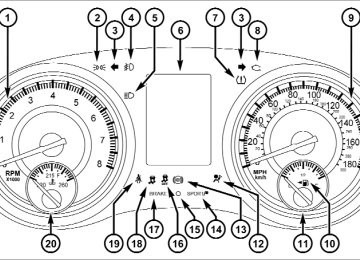
280 UNDERSTANDING YOUR INSTRUMENT PANEL INSTRUMENT CLUSTER
INSTRUMENT CLUSTER DESCRIPTIONS
1. Tachometer The red segments indicate the maximum permissible engine revolutions per minute (RPM x 1000) for each gear range. Before reaching the red area, ease up on the accelerator. 2. Park/Headlight ON Indicator — If Equipped
This indicator will illuminate when the park lights or headlights are turned on.
3. Turn Signal Indicators
The arrow will flash with the exterior turn signal when the turn signal lever is operated.
UNDERSTANDING YOUR INSTRUMENT PANEL 281
If the vehicle electronics sense that the vehicle is driven more than 1 mile (1.6 km) with either turn signal on, a continuous chime will sound to alert you to turn the signals off. If either indicator flashes at a rapid rate, check for a defective outside light bulb. 4. Front Fog Light Indicator — If EquippedThis indicator will illuminate when the front fog lights are on.
5. High Beam Indicator
This indicator shows that the high beam head- lights are on. Push the multifunction lever forward to switch the headlights to high beam, and pull toward yourself (normal position) to return to low beam.
282 UNDERSTANDING YOUR INSTRUMENT PANEL 6. Odometer Display / Electronic Vehicle Information Center (EVIC) Display
Odometer Display The odometer display shows the total distance the ve- hicle has been driven. U.S. Federal regulations require that upon transfer of vehicle ownership, the seller certify to the purchaser the correct mileage that the vehicle has been driven. If your odometer needs to be repaired or serviced, the repair technician should leave the odometer reading the same as it was before the repair or service. If s/he cannot do so, then the odometer must be set at zero, and a sticker must be placed in the door jamb stating what the mileage was before the repair or service. It is a good idea for you to make a record of the odometer reading before the repair/ service, so that you can be sure that it is properly reset, or that the door jamb sticker is accurate if the odometer must be reset at zero.
Electronic Vehicle Information Center (EVIC) Display The Electronic Vehicle Information Center (EVIC) fea- tures a driver-interactive display that is located in the instrument cluster. For further information, refer to “Electronic Vehicle Information Center (EVIC)”. The Shift Lever Indicator is self-contained within the EVIC display. It displays the gear position of the auto- matic transmission. NOTE: • You must apply the brakes before shifting from PARK. • The highest available transmission gear is displayed in the lower right corner of the Electronic Vehicle Infor- mation Center (EVIC) whenever the Electronic Range Select (ERS) feature is active. Use the +/- selector on the shift lever to activate ERS. Refer to “Automatic Transmission” in “Starting And Operating” for further information.
7. Tire Pressure Monitoring Telltale Light — If Equipped
Each tire, including the spare (if provided), should be checked monthly when cold and inflated to the inflation pressure recommended by the vehicle manufacturer on the vehicle placard or tire inflation pressure label. (If your vehicle has tires of a different size than the size indicated on the vehicle placard or tire inflation pressure label, you should determine the proper tire inflation pressure for those tires.) As an added safety feature, your vehicle has been equipped with a Tire Pressure Monitoring System (TPMS) that illuminates a low tire pressure telltale when
UNDERSTANDING YOUR INSTRUMENT PANEL 283
one or more of your tires is significantly under-inflated. Accordingly, when the low tire pressure telltale illumi- nates, you should stop and check your tires as soon as possible, and inflate them to the proper pressure. Driving on a significantly under-inflated tire causes the tire to overheat and can lead to tire failure. Under-inflation also reduces fuel efficiency and tire tread life, and may affect the vehicle’s handling and stopping ability. Please note that the TPMS is not a substitute for proper tire maintenance, and it is the driver’s responsibility to maintain correct tire pressure, even if under-inflation has not reached the level to trigger illumination of the TPMS low tire pressure telltale.284 UNDERSTANDING YOUR INSTRUMENT PANEL Your vehicle has also been equipped with a TPMS malfunction indicator to indicate when the system is not operating properly. The TPMS malfunction indicator is combined with the low tire pressure telltale. When the system detects a malfunction, the telltale will flash for approximately one minute and then remain continuously illuminated. This sequence will continue upon subse- quent vehicle start-ups as long as the malfunction exists. When the malfunction indicator is illuminated, the sys- tem may not be able to detect or signal low tire pressure as intended. TPMS malfunctions may occur for a variety of reasons, including the installation of replacement or alternate tires or wheels on the vehicle that prevent the TPMS from functioning properly. Always check the TPMS malfunction telltale after replacing one or more tires or wheels on your vehicle, to ensure that the replacement or alternate tires and wheels allow the TPMS to continue to function properly.
CAUTION!
The TPMS has been optimized for the original equipment tires and wheels. TPMS pressures and warning have been established for the tire size equipped on your vehicle. Undesirable system opera- tion or sensor damage may result when using re- placement equipment that is not of the same size, type, and/or style. Aftermarket wheels can cause sensor damage. Do not use tire sealant from a can or balance beads if your vehicle is equipped with a TPMS, as damage to the sensors may result.
8. Malfunction Indicator Light (MIL)
The Malfunction Indicator Light (MIL) is part of an onboard diagnostic system, called OBD, that monitors engine and automatic transmission con- trol systems. The light will illuminate when the key is in the ON/RUN position, before engine start. If the bulb does not come on when turning the key from OFF to ON/RUN, have the condition checked promptly. Certain conditions, such as poor fuel quality, etc., may illuminate the MIL after engine start. The vehicle should be serviced if the light stays on through several of your typical driving cycles. In most situations, the vehicle will drive normally and will not require towing.
UNDERSTANDING YOUR INSTRUMENT PANEL 285
CAUTION!
Prolonged driving with the MIL on could cause dam- age to the engine control system. It also could affect fuel economy and drivability. If the MIL is flashing, severe catalytic converter damage and power loss will soon occur. Immediate service is required.
WARNING!
A malfunctioning catalytic converter, as referenced above, can reach higher temperatures than in normal operating conditions. This can cause a fire if you drive slowly or park over flammable substances such as dry plants, wood, cardboard, etc. This could result in death or serious injury to the driver, occupants or others.
286 UNDERSTANDING YOUR INSTRUMENT PANEL 9. Speedometer Indicates vehicle speed. 10. Fuel Door Reminder
The arrow in this symbol is a reminder that the Fuel Filler Door is located on the left side of the vehicle.
11. Fuel Gauge The pointer shows the level of fuel in the fuel tank when the ignition switch is in the ON/RUN position. 12. Air Bag Warning Light
This light will turn on for four to eight seconds as a bulb check when the ignition switch is first turned to ON/RUN. If the light is either not on during starting, stays on, or turns on while driving, have the system inspected at an authorized dealer as soon as possible. Refer to “Occupant Restraints” in “Things To Know Before Starting Your Vehicle” for further information.
13. Anti-Lock Brake (ABS) Light
This light monitors the Anti-Lock Brake System (ABS). The light will turn on when the ignition switch is turned to the ON/RUN position and may stay on for as long as four seconds.
If the ABS light remains on or turns on while driving, it indicates that the Anti-Lock portion of the brake system is not functioning and that service is required. However, the conventional brake system will continue to operate normally if the BRAKE warning light is not on. If the ABS light is on, the brake system should be serviced as soon as possible to restore the benefits of Anti-Lock brakes. If the ABS light does not turn on when the ignition switch is turned to the ON/RUN position, have the light inspected by an authorized dealer.
14. Sport Mode
This light will illuminate when Sport or Track mode is selected. When Sport mode is selected, the EVIC will display “Sport Mode Active (Suspension)”.
This mode provides performance based tuning with improved handling through an electronic controlled damping system. This system reduces body roll and pitch in many driving situations including cornering, accelera- tion and braking. When Track Mode is Selected, the EVIC will display “Track Mode Activated (Suspension and Transmission)”. In addition to SPORT suspension, Track mode also affects transmission shifting in either Auto or Manual mode. Refer to “AutoStick” in “Starting And Operating” for further information. The transmission has a sportier, more aggressive shift pattern. In Manual mode, the transmission will hold gear at redline during manual shifting (console shifter or paddle switches).
UNDERSTANDING YOUR INSTRUMENT PANEL 287
15. Vehicle Security Light — If Equipped
This light will flash at a fast rate for approxi- mately 15 seconds, when the vehicle security alarm is arming, and then will flash slowly until the vehicle is disarmed.
16. Electronic Stability Control (ESC) OFF Indicator Light — If Equipped
This light indicates the Electronic Stability Con- trol (ESC) is off.
17. Brake Warning Light
This light monitors various brake functions, including brake fluid level and parking brake application. If the brake light turns on it may indicate that the parking brake is applied, that the brake fluid level is low, or that there is a problem with the anti-lock brake system reservoir.
288 UNDERSTANDING YOUR INSTRUMENT PANEL If the light remains on when the parking brake has been disengaged, and the fluid level is at the full mark on the master cylinder reservoir, it indicates a possible brake hydraulic system malfunction or that a problem with the Brake Booster has been detected by the Anti-Lock Brake System (ABS) / Electronic Stability Control (ESC) system. In this case, the light will remain on until the condition has been corrected. If the problem is related to the brake booster, the ABS pump will run when applying the brake and a brake pedal pulsation may be felt during each stop. The dual brake system provides a reserve braking capac- ity in the event of a failure to a portion of the hydraulic system. A leak in either half of the dual brake system is indicated by the Brake Warning Light, which will turn on when the brake fluid level in the master cylinder has dropped below a specified level.
The light will remain on until the cause is corrected. NOTE: The light may flash momentarily during sharp cornering maneuvers, which change fluid level condi- tions. The vehicle should have service performed, and the brake fluid level checked. If brake failure is indicated, immediate repair is neces- sary.
WARNING!
Driving a vehicle with the red brake light on is dangerous. Part of the brake system may have failed. It will take longer to stop the vehicle. You could have a collision. Have the vehicle checked immediately.
Vehicles equipped with the Anti-Lock Brake System (ABS), are also equipped with Electronic Brake Force Distribution (EBD). In the event of an EBD failure, the Brake Warning Light will turn on along with the ABS Light. Immediate repair to the ABS system is required. Operation of the Brake Warning Light can be checked by turning the ignition switch from the OFF position to the ON/RUN position. The light should illuminate for ap- proximately two seconds. The light should then turn off unless the parking brake is applied or a brake fault is detected. If the light does not illuminate, have the light inspected by an authorized dealer. The light also will turn on when the parking brake is applied with the ignition switch in the ON/RUN position. NOTE: This light shows only that the parking brake is applied. It does not show the degree of brake application.
UNDERSTANDING YOUR INSTRUMENT PANEL 289
18. Electronic Stability Control (ESC) Activation/ Malfunction Indicator Light — If Equipped
The “ESC Activation/Malfunction Indicator Light” in the instrument cluster will come on when the ignition switch is turned to the ON/RUN position. It should go out with the engine running. If the “ESC Activation/Malfunction In- dicator Light” comes on continuously with the engine running, a malfunction has been detected in the ESC system. If this light remains on after several ignition cycles, and the vehicle has been driven several miles (kilometers) at speeds greater than 30 mph (48 km/h), see your authorized dealer as soon as possible to have the problem diagnosed and corrected.
290 UNDERSTANDING YOUR INSTRUMENT PANEL NOTE: • The “ESC Off
Indicator Light” and the “ESC Activation/Malfunction Indicator Light” come on mo- mentarily each time the ignition switch is turned to ON/RUN. • Each time the ignition is turned to ON/RUN, the ESC system will be ON, even if it was turned off previously. • The ESC system will make buzzing or clicking sounds when it is active. This is normal; the sounds will stop when ESC becomes inactive following the maneuver that caused the ESC activation.
19. Seat Belt Reminder Light
When the ignition switch is first turned to ON/ RUN, this light will turn on for four to eight seconds as a bulb check. During the bulb check, if the driver’s seat belt is unbuckled, a chime will sound. After the bulb check or when driving, if the driver’s seat belt remains unbuckled, the Seat Belt Reminder Light will illuminate and the chime will sound. Refer to “Occupant Restraints” in “Things To Know Before Start- ing Your Vehicle” for further information. 20. Temperature Gauge The temperature gauge shows engine coolant tempera- ture. Any reading within the normal range indicates that the engine cooling system is operating satisfactorily.
The gauge pointer will likely indicate a higher tempera- ture when driving in hot weather, up mountain grades, or when towing a trailer. It should not be allowed to exceed the upper limits of the normal operating range.
CAUTION!
Driving with a hot engine cooling system could damage your vehicle. If the temperature gauge reads “260” pull over and stop the vehicle. Idle the vehicle with the air conditioner turned off until the pointer drops back into the normal range. If the pointer remains on the “260” and you hear continuous chimes, turn the engine off immediately and call an authorized dealership for service.
UNDERSTANDING YOUR INSTRUMENT PANEL 291
WARNING!
A hot engine cooling system is dangerous. You or others could be badly burned by steam or boiling coolant. You may want to call an authorized dealer- ship for service if your vehicle overheats. If you decide to look under the hood yourself, see “Main- taining Your Vehicle”. Follow the warnings under the Cooling System Pressure Cap paragraph.
292 UNDERSTANDING YOUR INSTRUMENT PANEL ELECTRONIC VEHICLE INFORMATION CENTER (EVIC) The Electronic Vehicle Information Center (EVIC) fea- tures a driver-interactive display that is located in the instrument cluster.
Electronic Vehicle Information Center (EVIC)
This system allows the driver to select a variety of useful information by pressing the switches mounted on the steering wheel. The EVIC consists of the following: • Radio Info • Fuel Economy Info • Cruise Control Info • Digital Vehicle Speed • Trip Info • Tire Pressure • Vehicle Info Messages • Stored Warning Messages • Turn Menu OFF
The system allows the driver to select information by pressing the following buttons mounted on the steering wheel:
UNDERSTANDING YOUR INSTRUMENT PANEL 293
UP Button
Press and release the UP button to scroll upward through the main menu and Vehicle Info and Trip Info sub-menus (Fuel Economy, Vehicle Info, Tire PSI, Cruise, Messages) and sub-menus.
DOWN Button
Press and release the DOWN button to scroll downward through the main menus and Ve- hicle Info and Trip Info sub-menus.
SELECT Button
Press and release the SELECT button to access the information screens or sub-menu screens of a main menu item. Press and hold the SELECT button for two seconds to reset displayed/
EVIC Steering Wheel Buttons
selected features that can be reset.
294 UNDERSTANDING YOUR INSTRUMENT PANEL BACK Button
Press the BACK button to return to the main menu from an info screen or sub-menu item.
Electronic Vehicle Information Center (EVIC) Displays The EVIC display consists of three sections: 1. The top line where compass direction, odometer line and outside temperature are displayed. 2. The main display area where the menus and pop up messages are displayed. 3. The reconfigurable telltales section.
The main display area will normally display the main menu or the screens of a selected feature of the main menu. The main display area also displays ⬙pop up⬙ messages that consist of approximately 60 possible warn- ing or information messages. These pop up messages fall into several categories: • Five Second Stored Messages When the appropriate conditions occur, this type of message takes control of the main display area for five seconds and then returns to the previous screen. Most of the messages of this type are then stored (as long as the condition that activated it remains active) and can be reviewed from the ⬙Messages⬙ main menu item. As long as there is a stored message, an ⬙i⬙ will be displayed in the EVIC’s compass/outside temp line. Examples of this message type are ⬙Right Front Turn Signal Lamp Out⬙ and ⬙Low Tire Pressure⬙.
• Unstored Messages This message type is displayed indefinitely or until the condition that activated the message is cleared. Examples of this message type are ⬙Turn Signal On⬙ (if a turn signal is left on) and ⬙Lights On⬙ (if driver leaves the vehicle). • Unstored Messages Until RUN These messages deal primarily with the Remote Start feature. This message type is displayed until the ignition is in the RUN state. Examples of this message type are ⬙Remote Start Aborted - Door Ajar⬙ and ⬙Press Brake Pedal and Push Button to Start⬙. • Five Second Unstored Messages When the appropriate conditions occur, this type of message takes control of the main display area for five seconds and then returns to the previous screen. Ex- amples of this message type are ⬙Memory System Un- available - Not in Park⬙ and ⬙Automatic High Beams On⬙.
UNDERSTANDING YOUR INSTRUMENT PANEL 295
The Reconfigurable Telltales section is divided into the white telltales area on the right, amber telltales in the middle, and red telltales on the left. EVIC White Telltales This area will show reconfigurable white caution tell- tales. These telltales include: • Shift Lever Status The selected AutoStick gear is displayed as ⬙1⬙, ⬙2⬙, ⬙3⬙, ⬙4⬙, ⬙5⬙, or⬙6⬙ and indicate the Electronic Range Select (ERS) feature has been engaged and the gear selected is displayed. For further information on ERS, refer to “Starting And Operating”. • Electronic Speed Control ONThis telltale will illuminate when the electronic speed control is ON. For further information, refer to “Electronic Speed Control” in “Under- standing The Features Of Your Vehicle.”
296 UNDERSTANDING YOUR INSTRUMENT PANEL
• Electronic Speed Control SET
This telltale will illuminate when the electronic speed control is SET. For further information, refer to “Electronic Speed Control” in “Under- standing The Features Of Your Vehicle.”
• Adaptive Cruise Control (ACC) ON
This telltale will illuminate when the ACC is ON. For further information, refer to “Adap- tive Cruise Control (ACC)” in “Understanding The Features Of Your Vehicle.” • Adaptive Cruise Control (ACC) SET
This telltale will illuminate when the ACC is SET. For further information, refer to “Adap- tive Cruise Control (ACC)” in “Understanding The Features Of Your Vehicle.”
EVIC Amber Telltales This area will show reconfigurable amber caution tell- tales. These telltales include: • Forward Collision Warning (FCW) OFF
This telltale informs the driver that the For- ward Collision Warning feature is Off. The telltale is On when the front radar sensor is blocked and requires cleaning, the ACC/FCW sensors require service, or the ACC/FCW system is unavailable because of a system error. For further infor- mation, refer to “Adaptive Cruise Control (ACC)” in “Understanding The Features Of Your Vehicle.” • Low Fuel Telltale
When the fuel level reaches approximately 3.0 gal (11.0 L) this light will turn on, and remain on until fuel is added.
• Windshield Washer Fluid Low Indicator
This telltale will turn on to indicate the wind- shield washer fluid is low.
• Trunk Ajar
This light will turn on to indicate that the trunk lid is ajar.
UNDERSTANDING YOUR INSTRUMENT PANEL 297
• Adaptive Cruise Control (ACC) Malfunction
This light will turn on when a ACC is not operating and needs service. For further infor- mation, refer to “Adaptive Cruise Control (ACC)” in “Understanding The Features Of
Your Vehicle.” EVIC Red Telltales This area will show reconfigurable red telltales. These telltales include: • Door Ajar
This telltale turns on when one or more doors are ajar. The telltale will show which doors are ajar.
• Oil Pressure Warning Telltale
This telltale indicates low engine oil pressure. If the light turns on while driving, stop the vehicle and shut off the engine as soon as possible. A chime will sound when this light turns on. Do not operate the vehicle until the cause is corrected. This light does not show how much oil is in the engine. The engine oil level must be checked under the hood. • Charging System Telltale
This telltale shows the status of the electrical charging system. If the telltale stays on or comes on while driving, turn off some of the vehicle’s non- essential electrical devices or increase engine speed (if at
298 UNDERSTANDING YOUR INSTRUMENT PANEL idle). If the charging system telltale remains on, it means that the vehicle is experiencing a problem with the charging system. Obtain SERVICE IMMEDIATELY. See an authorized dealer. If jump starting is required, refer to “Jump Starting Procedures” in “What To Do In Emergencies”. • Electronic Throttle Control (ETC) Telltale
This telltale informs you of a problem with the Electronic Throttle Control (ETC) system. If the telltale comes on while driving, have the sys- tem checked by an authorized dealer.
If a problem is detected, the telltale will come on while the engine is running. Cycle the ignition key when the vehicle has completely stopped and the shift lever is placed in the PARK position. The telltale should turn off.
If the telltale remains lit with the engine running, your vehicle will usually be drivable. However, see an autho- rized dealer for service as soon as possible. If the telltale is flashing when the engine is running, immediate service is required. You may experience reduced performance, an elevated/rough idle or engine stall and your vehicle may require towing. • Engine Temperature Warning Telltale
This telltale warns of an overheated engine condi- tion. As temperatures rise and the gauge ap- proaches H, or 260°F, this telltale will illuminate and a single chime will sound after reaching a set threshold. Further overheating will cause the tempera- ture gauge to pass H, or 260°F, a continuous chime will occur until the engine is allowed to cool.
If the telltale turns on while driving, safely pull over and stop the vehicle. If the A/C system is on, turn it off. Also, shift the transmission into NEUTRAL and idle the ve- hicle. If the temperature reading does not return to normal, turn the engine off immediately and call for service. Refer to “If Your Engine Overheats” in “What To Do In Emergencies” for more information. • Transmission Temperature Warning Telltale
This telltale indicates that the transmission fluid temperature is running hot. This may occur with severe usage, such as trailer towing. If this telltale turns on, safely pull over and stop the vehicle. Then, shift the transmission into NEU- TRAL and run the engine at idle or faster until the light turns off.
UNDERSTANDING YOUR INSTRUMENT PANEL 299
CAUTION!
Continuous driving with the Transmission Tempera- ture Warning Telltale illuminated will eventually cause severe transmission damage or transmission failure.
WARNING!
If the Transmission Temperature Warning Telltale is illuminated and you continue operating the vehicle, in some circumstances you could cause the fluid to boil over, come in contact with hot engine or exhaust components and cause a fire. • Electric Power Steering Malfunction
This telltale is on when the Electric Power Steering is not operating and needs service.
300 UNDERSTANDING YOUR INSTRUMENT PANEL Oil Change Required Your vehicle is equipped with an engine oil change indicator system. The ⬙Oil Change Due⬙ message will display in the EVIC for five seconds after a single chime has sounded at the start of each ignition that an oil change is due. The engine oil change indicator system is duty cycle based, which means the engine oil change interval may fluctuate dependent upon your personal driving style. Unless reset, this message will continue to display each time you cycle the ignition to the ON/RUN position. To turn off the message temporarily, press and release the MENU button. To reset the oil change indicator system (after performing the scheduled maintenance), perform the following procedure: 1. Without pressing the brake pedal, push the ENGINE START/STOP button and cycle the ignition to the ON/ RUN position (Do not start the engine.)
2. Fully depress the accelerator pedal, slowly, three times within 10 seconds. 3. Without pressing the brake pedal, push the ENGINE START/STOP button once to return the ignition to the OFF/LOCK position. If the indicator message illuminates when you NOTE: start the vehicle, the oil change indicator system did not reset. If necessary, repeat this procedure. Fuel Economy Press and release the UP or DOWN button until ⬙Fuel Economy⬙ is highlighted. Press the SELECT button and the next screen will display the following: • Average Fuel Economy/Miles Per Gallon • Distance To Empty (DTE) • Miles Per Gallon (MPG)
Press the SELECT button to reset the Average Fuel Economy. Press the BACK button to return to the main menu. Average Fuel Economy / ECO Fuel Saver Mode — If Equipped Shows the average fuel economy since the last reset. When Average Fuel Economy is selected, The word ⬙RESET>⬙ (with right arrow) appears next to it. Pressing the right arrow button will reset Average Fuel Economy which displays ⬙0⬙ immediately after reset. Then, the history information will be erased, and the averaging will continue from the last fuel average reading before the reset.
UNDERSTANDING YOUR INSTRUMENT PANEL 301
Average Fuel Economy
302 UNDERSTANDING YOUR INSTRUMENT PANEL There is an ECO icon between the Compass and Outside Temperature info at the top of the EVIC display. This icon will appear whenever the Multi-Displacement System (MDS) (if equipped) allows the engine to operate on four cylinders, or if you are driving in a fuel efficient manner. This feature allows you to monitor when you are driving in a fuel efficient manner, and it can be used to modify driving habits in order to increase fuel economy. Press the BACK button to return to the main menu. Distance To Empty (DTE) Shows the estimated distance that can be traveled with the fuel remaining in the tank. This estimated distance is determined by a weighted average of the instantaneous and average fuel economy, according to the current fuel tank level. DTE cannot be reset through the SELECT button.
NOTE: Significant changes in driving style or vehicle loading will greatly affect the actual drivable distance of the vehicle, regardless of the DTE displayed value. When the DTE value is less than 30 miles (48 km) estimated driving distance, the DTE display will change to a “LOW FUEL” message. This display will continue until the vehicle runs out of fuel. Adding a significant amount of fuel to the vehicle will turn off the “LOW FUEL” message and a new DTE value will display. Press the BACK button to return to the main menu. Miles Per Gallon (MPG) The Miles Per Gallon (MPG) feature displays instanta- neous fuel economy in a bar graph below the DTE, this function cannot be reset. Press the BACK button to return to the main menu.
Cruise Control Press and release the UP or DOWN button until ⬙ACC⬙ (if equipped with Adaptive Cruise Control) or ⬙Cruise⬙ is highlighted in the EVIC. Status of the ACC or Cruise is displayed in the menu line also. Press and release the SELECT (right arrow) button to display the following information: • If equipped with ACC, one of several messages will be displayed giving a dynamic update of the status of the feature as the driver changes feature status or follow- ing conditions change. If ACC is active and a warning or other feature is in the EVIC main display, the ACC status will be displayed in place of the EVIC odometer line. • For vehicles with Cruise, one of several messages will be displayed giving a dynamic update of the status of the feature as the driver changes feature status or
UNDERSTANDING YOUR INSTRUMENT PANEL 303
conditions change. If Cruise is active and a warning or other feature is in the EVIC main display, the Cruise status will be displayed in place of the EVIC odometer line.Press and release the BACK button to return to the main menu. Vehicle Speed Press and release the UP or DOWN button until ⬙Vehicle Speed⬙ is highlighted in the EVIC. Press the SELECT button to view a digital display of the current speed in mph or km/h. Pressing the SELECT button a second time will toggle the unit of measure between mph or km/h. Press the BACK button to return to the main menu. NOTE: Changing the unit of measure in the Vehicle Speed menu will not change the unit of measure in the EVIC.
304 UNDERSTANDING YOUR INSTRUMENT PANEL Trip Info Press and release the UP or DOWN button until ⬙Trip Info⬙ is highlighted in the EVIC. Press and release the SELECT button to display the following three trip features in the next screen: • Trip A • Trip B • Elapsed Time Press the UP/DOWN buttons to cycle through all the Trip Computer functions or press the BACK button to return to the main menu.
The Trip Functions mode displays the following information: Trip A Shows the total distance traveled for Trip A since the last reset. Trip B Shows the total distance traveled for Trip B since the last reset. Elapsed Time Shows the total elapsed time of travel since the last reset. Elapsed time will increment when the ignition is in the ON or START position. Resetting A Trip Info Function To Reset any of the three Trip Info functions, select the function you want to reset using the UP or DOWN buttons. Push the SELECT button until the feature displays zero.
Tire PSI Press and release the UP or DOWN button until ⬙Tire PSI⬙ is highlighted in the EVIC. Press and release the SELECT button and one of the following will be displayed: • If tire pressure is OK for all tires a vehicle ICON is displayed with tire pressure values in each corner of the ICON. • If one or more tires have low pressure, ⬙Tire Pressure LOW⬙ is displayed with the vehicle ICON and the tire pressure values in each corner of the ICON. • If the Tire Pressure system requires service, ⬙Service
Tire Pressure System⬙ is displayed.
Tire PSI is an information only function and cannot be reset. Press and release the BACK button to return to the main menu.
UNDERSTANDING YOUR INSTRUMENT PANEL 305
SRT
WARNING!
Measurement of vehicle statistics with the Perfor- mance Features is intended for off-highway or off- road use only and should not be done on any public roadways. It is recommended that these features be used in a controlled environment and within the limits of the law. The capabilities of the vehicle as measured by the performance pages must never be exploited in a reckless or dangerous manner, which can jeopardize the user’s safety or the safety of others. Only a safe, attentive, and skillful driver can prevent accidents.
306 UNDERSTANDING YOUR INSTRUMENT PANEL The Performance Features include the following: • 0-60 mph (0-100 km/h) • Braking Distance • 1/8 Mile • 1/4 Mile • Instantaneous G-Force • Peak G-Force To access, press and release either the UP or DOWN arrow button until “SRT” appears in the EVIC, then press and release the SELECT button. Press the UP or DOWN button to cycle through the features. Press the SELECT button to select a feature.
The following describes each feature and its operation: 0-60 mph (0-100 km/h) When selected, this screen displays the time it takes for the vehicle to go from 0 to 60 mph (0 to 100 km/h) within 10 seconds. • The feature will “ready” when the vehicle speed is at 0 mph (0 km/h). The word “READY” will appear when conditions are met for the event to begin. • The screen will revert back to “Please come to a complete stop, Not Ready”, if the vehicle fails to reach 60 mph (100 km/h) in less then 10 seconds. • The time will continue to display until the SELECT button is pressed or the vehicles is brought to a stop.
brakes at speeds above 30 mph (48 km/h).
Braking Distance When selected, this screen displays the vehicle’s braking distance and the speed at which the brake pedal was depressed. • This feature will only function when applying the • Engaging the parking brake will disable this feature. • The word “READY” will display when conditions are • The distance and speed measurements display while • The distance measurement will be aborted if the brake pedal is released before the vehicle comes to a com- plete stop.
met for the event to begin.
the event is taking place.
UNDERSTANDING YOUR INSTRUMENT PANEL 307
• The distance and speed measurements will continue to display until the conditions are met for another event to be recorded. • Pressing the SELECT button will clear the current run
and prepare the cluster to record a new run.
1/8 Mile, 1/4 Mile When selected, this screen displays the time it takes the vehicle to travel 1/8 mile (1/4 mile) within 25 seconds. • The feature will “ready” when the vehicle is at 0 mph (0 km/h). The word “READY” will display when conditions are met for the event to begin. • 0.0s will display if the vehicle fails to reach 1/8 mile • The time will continue to display until the vehicle is
(1/4 mile) in less then 25 seconds.
brought to a stop.
308 UNDERSTANDING YOUR INSTRUMENT PANEL Instantaneous G-Force When selected, this screen displays the current G-Force (lateral and longitudinal). Peak G-Force When selected, this screen displays all four G-Force values (two lateral and two longitudinal). • When a force greater than zero is measured, the display will update the value as it climbs. As the G-Force falls, the peak forces will continue to display. • Pressing and holding the SELECT button for five
seconds will clear the peak force values.
Vehicle Info (Customer Information Features) Press and release the UP or DOWN button until ⬙Vehicle Info⬙ is highlighted in the EVIC. Press and release the SELECT button and Coolant Temp will be displayed. Press the UP or DOWN button to scroll through the following information displays. • Coolant Temp Displays the actual coolant temperature. • Oil Temperature Displays the actual oil temperature. • Oil Pressure Displays the actual oil pressure. • Trans Temperature Displays the actual transmission temperature. • Engine Hours Displays the number of hours of engine operation.
UNDERSTANDING YOUR INSTRUMENT PANEL 309
Hard-Keys Hard-Keys are located below the Uconnect Touch™ system in the center of the instrument panel. In addition, there is a Scroll/Enter control knob located on the right side of the Climate Controls in the center of the instru- ment panel. Turn the control knob to scroll through menus and change settings (i.e., 30, 60, 90), press the center of the control knob one or more times to select or change a setting (i.e., ON, OFF). Soft-Keys Soft-Keys are accessible on the Uconnect Touch™ display.
Messages # Select from Main Menu using the UP or DOWN buttons. This feature shows the number of stored warning mes- sages (in the # place holder). Pressing the SELECT button will allow you to see what the stored messages are. Pressing the BACK button takes you back to the Main Menu. Turn Menu OFF Select from Main Menu using the DOWN button. Press- ing the SELECT button blanks the menu display. Pressing any one of the four steering wheel buttons brings the menu back.
Uconnect Touch™ SETTINGS The Uconnect Touch™ system uses a combination of soft and hard keys located on the center of the instrument panel that allows you to access and change the customer programmable features.
310 UNDERSTANDING YOUR INSTRUMENT PANEL Customer Programmable Features — Uconnect Touch™ System 8.4 Settings Press the More soft-key, then press the Settings soft-key to display the menu setting screen. In this mode the Uconnect Touch™ system allows you to access program- mable features that may be equipped such as Display, Clock, Safety/Assistance, Lights, Doors & Locks, Auto-On Comfort & Remote Start, Engine Off Operation, Compass Settings, Audio, Phone/Bluetooth and SIRIUS Setup. NOTE: Only one touchscreen area may be selected at a time.
Uconnect Touch™ 8.4 Soft-Keys
When making a selection, press the soft-key to enter the desired mode. Once in the desired mode press and release the preferred setting until a check-mark appears next to the setting, showing that setting has been selected.
Once the setting is complete press the Back Arrow soft-key to return to the previous menu or press the X soft-key to close out of the settings screen. Pressing the Up or Down Arrow soft-keys on the right side of the screen will allow you to toggle up or down through the available settings. Display After pressing the Display soft-key the following settings will be available. • Display Mode When in this display you may select one of the auto display settings. To change Mode status, touch and release the Day, Night or Auto soft-key. Then touch the arrow back soft-key. • Display Brightness With Headlights ON When in this display, you may select the brightness with the headlights on. Adjust the brightness with the + and –
UNDERSTANDING YOUR INSTRUMENT PANEL 311
setting soft-keys or by selecting any point on the scale between the + and – soft-keys. Then touch the arrow back soft-key. • Display Brightness With Headlights OFF When in this display, you may select the brightness with the headlights off. Adjust the brightness with the + and – setting soft-keys or by selecting any point on the scale between the + and – soft-keys. Then touch the arrow back soft-key. • Set Language When in this display, you may select one of three languages for all display nomenclature, including the trip functions and the navigation system (if equipped). Touch the Set Language soft-key and then touch the desired language soft-key until a check-mark appears next to the language, showing that setting has been selected. Touch the back arrow soft-key to return to the previous menu.312 UNDERSTANDING YOUR INSTRUMENT PANEL
• Units When in this display, you may select to have the EVIC, odometer, and navigation system (if equipped) changed between US and Metric units of measure. Touch US or Metric until a check-mark appears next to the setting, showing that setting has been selected. Touch the back arrow soft-key to return to the previous menu. • Voice Response Length When in this display, you may change the Voice Re- sponse Length settings. To change the Voice Response Length, touch the Brief or Detailed soft-key until a check-mark appears next to the setting, showing that setting has been selected. Touch the back arrow soft-key to return to the previous menu. • Touchscreen Beep When in this display, you may turn on or shut off the sound heard when a touch screen button (soft-key) is pressed. Touch the Touchscreen Beep soft-key until a
check-mark appears next to the setting, showing that setting has been selected. Touch the back arrow soft-key to return to the previous menu. • Navigation Turn-By-Turn In Cluster When this feature is selected, the turn-by-turn directions will appear in the display as the vehicle approaches a designated turn within a programmed route. To make your selection, touch the Navigation Turn-By-Turn In Cluster soft-key, until a check-mark appears next to the setting, showing that setting has been selected. Touch the back arrow soft-key to return to the previous menu. • Fuel Saver Display In Cluster The “ECO” message is located in the instrument cluster display, this message can be turned on or off. To make your selection, touch the Fuel Saver Display soft-key, until a check-mark appears next to the setting, showing that setting has been selected. Touch the back arrow soft-key to return to the previous menu.
Clock After pressing the Clock soft-key the following settings will be available. • Sync Time With GPS When in this display, you may automatically have the radio set the time. To change the Sync Time setting touch the Sync with GPS Time soft-key until a check-mark appears next to the setting, showing that setting has been selected. Touch the back arrow soft-key to return to the previous menu. • Set Time Hours When in this display, you may adjust the hours. The Sync with GPS Time soft-key must be unchecked. To make your selection touch the + or - soft-keys to adjust the hours up or down. Touch the back arrow soft-key to return to the previous menu or touch the X soft-key to close out of the settings screen.
UNDERSTANDING YOUR INSTRUMENT PANEL 313
• Set Time Minutes When in this display, you may adjust the minutes. The Sync with GPS Time soft-key must be unchecked. To make your selection touch the + or - soft-keys to adjust the minutes up or down. Touch the back arrow soft-key to return to the previous menu or touch the X soft-key to close out of the settings screen. • Time Format When in this display, you may select the time format display setting. Touch the Time Format soft-key until a check-mark appears next to the 12hrs or 24hrs setting, showing that setting has been selected. Touch the back arrow soft-key to return to the previous menu. • Show Time In Status Bar When in this display, you may turn on or shut off the digital clock in the status bar. To change the Show Time Status setting touch the Show Time in Status Bar soft-key
314 UNDERSTANDING YOUR INSTRUMENT PANEL until a check-mark appears next to setting, showing that setting has been selected. Touch the back arrow soft-key to return to the previous menu. Safety / Assistance After pressing the Safety / Assistance soft-key the fol- lowing settings will be available. • Front Collision Sensitivity — If Equipped The Front Collision Warning (FCW) feature can be can be set to Far, set to Near or turned Off. The default status of FCW is the Far setting. This means the system will warn you of a possible collision with the vehicle in front of you when you are farther away. This gives you the most reaction time. To change the setting for more dynamic driving, select the Near setting. This warns you of a possible collision when you are much closer to the vehicle in front of you. This allows for a more dynamic driving experience. To change the FCW status, touch and release the OFF, Near or Far button. Then touch the arrow back soft-key.
For further information, refer to “Adaptive Cruise Con- trol (ACC)” in “Understanding The Features Of Your Vehicle”. • Park Assist The Rear Park Assist system will scan for objects behind the vehicle when the transmission shift lever is in RE- VERSE and the vehicle speed is less than 11 mph (18 km/h). The system can be enabled with Sound Only, Sound and Display, or turned OFF. To change the Park Assist status, touch and release the OFF, Sound Only or Sounds and Display button. Then touch the arrow back soft-key. Refer to “ParkSense威 Rear Park Assist” in “Understanding The Features Of Your Vehicle” for sys- tem function and operating information. • Tilt Mirrors In Reverse When this feature is selected, the outside sideview mir- rors will tilt downward when the ignition is in the RUN position and the transmission shift lever is in the RE- VERSE position. The mirrors will move back to their
previous position when the transmission is shifted out of REVERSE. To make your selection, touch the Tilt Mirrors In Reverse soft-key, until a check-mark appears next to setting, showing that setting has been selected. Touch the back arrow soft-key to return to the previous menu. • Blind Spot Alert When this feature is selected, the Blind Spot Alert feature can be set to Off, Lights or Lights and Chime. The Blind Spot Alert feature can be activated in “Lights” mode. When this mode is selected, the Blind Spot Monitor (BSM) system is activated and will only show a visual alert in the outside mirrors. When “Lights & Chime” mode is activated, the Blind Spot Monitor (BSM) will show a visual alert in the outside mirrors as well as an audible alert when the turn signal is on. When “Off” is selected, the Blind Spot Monitor (BSM) system is deacti- vated. To change the Blind Spot Alert status, touch the Off, Lights or Lights & Chime soft-key. Then touch the arrow back soft-key.
UNDERSTANDING YOUR INSTRUMENT PANEL 315
If your vehicle has experienced any damage in NOTE: the area where the sensor is located, even if the fascia is not damaged, the sensor may have become misaligned. Take your vehicle to an authorized dealer to verify sensor alignment. Having a sensor that is misaligned will result in the BSM not operating to specification. • ParkView威 Backup Camera Your vehicle may be equipped with the ParkView威 Rear Back Up Camera that allows you to see an on-screen image of the rear surroundings of your vehicle whenever the shift lever is put into REVERSE. The image will be displayed on the radio touchscreen display along with a caution note to “check entire surroundings” across the top of the screen. After five seconds, this note will disappear. The ParkView威 camera is located on the rear of the vehicle above the rear License plate. To make your selection, touch the ParkView威 Backup Camera soft-key, until a check-mark appears next to setting, showing that setting has been selected. Touch the back arrow soft-key to return to the previous menu.316 UNDERSTANDING YOUR INSTRUMENT PANEL
• Rain Sensing Auto Wipers When this feature is selected, the system will automati- cally activate the windshield wipers if it senses moisture on the windshield. To make your selection, touch the Rain Sensing soft-key, until a check-mark appears next to setting, showing that setting has been selected. Touch the back arrow soft-key to return to the previous menu. • Hill Start Assist — If Equipped When this feature is selected, the Hill Start Assist (HSA) system is active. Refer to “Electronic Brake Control Sys- tem” in “Starting And Operating” for system function and operating information. To make your selection, touch the Hill Start Assist soft-key, until a check-mark appears next to setting, showing that setting has been selected. Touch the back arrow soft-key to return to the previous menu. Lights After pressing the Lights soft-key the following settings will be available.
• Headlight Illumination On Approach When this feature is selected, the headlights will activate and remain on for 0, 30, 60, or 90 seconds when the doors are unlocked with the Remote Keyless Entry (RKE) transmitter. To change the Illuminated Approach status, touch the + or - soft-key to select your desired time interval. Touch the back arrow soft-key to return to the previous menu. • Headlights With Wipers — If Equipped When this feature is selected, and the headlight switch is in the AUTO position, the headlights will turn on ap- proximately 10 seconds after the wipers are turned on. The headlights will also turn off when the wipers are turned off if they were turned on by this feature. To make your selection, touch the Headlights With Wipers soft- key, until a check-mark appears next to setting, showing that setting has been selected. Touch the back arrow soft-key to return to the previous menu.
• Auto Dim High Beams “SmartBeam™” — If
Equipped
When this feature is selected, the high beam headlights will deactivate automatically under certain conditions. To make your selection, touch the Auto High Beams soft- key, until a check-mark appears next to setting, showing that setting has been selected. Touch the back arrow soft-key to return to the previous menu. Refer to “Lights/ SmartBeam™ — If Equipped” in “Understanding The Features Of Your Vehicle” for further information. • Daytime Running Lights When this feature is selected, the headlights will turn on whenever the engine is running. To make your selection, touch the Daytime Running Lights soft-key, until a check-mark appears next to setting, showing that setting has been selected. Touch the back arrow soft-key to return to the previous menu.
UNDERSTANDING YOUR INSTRUMENT PANEL 317
• Steering Directed Lights When this feature is selected, the headlights turn relative to a change in direction of the steering wheel. To make your selection, touch the Steering Directed Lights soft- key, until a check-mark appears next to setting, showing that setting has been selected. Touch the back arrow soft-key to return to the previous menu. • Flash Headlights With Lock When this feature is selected, the headlights will flash when the doors are locked or unlocked with the Remote Keyless Entry (RKE) transmitter. This feature may be selected with or without the sound horn on lock feature selected. To make your selection, touch the Flash Head- lights with Lock soft-key, until a check-mark appears next to setting, showing that setting has been selected. Touch the back arrow soft-key to return to the previous menu.
318 UNDERSTANDING YOUR INSTRUMENT PANEL Doors & Locks After pressing the Doors & Locks soft-key the following settings will be available. • Auto Unlock On Exit When this feature is selected, all doors will unlock when the vehicle is stopped and the transmission is in the PARK or NEUTRAL position and the driver’s door is opened. To make your selection, touch the Auto Unlock On Exit soft-key, until a check-mark appears next to setting, showing that setting has been selected. Touch the back arrow soft-key to return to the previous menu. • Flash Headlight With Lock When this feature is selected, the front and headlights will flash when the doors are locked or unlocked with the Remote Keyless Entry (RKE) transmitter. To make your selection, touch the Flash Lights With Lock soft-key, until a check-mark appears next to setting, showing that setting has been selected. Touch the back arrow soft-key to return to the previous menu.
• Sound Horn With Lock When this feature is selected, the horn will sound when the remote start is activated. To make your selection, touch the Sound Horn With Lock soft-key, until a check- mark appears next to setting, showing that setting has been selected. Touch the back arrow soft-key to return to the previous menu. • Sound Horn With Remote Start When this feature is selected, the horn will sound when the remote start is activated. To make your selection, touch the Sound Horn With Remote Start soft-key, until a check-mark appears next to setting, showing that setting has been selected. Touch the back arrow soft-key to return to the previous menu. • 1st Press Of Key Fob Unlocks When 1st Press Of Key Fob Unlocks is selected, only the driver’s door will unlock on the first press of the Remote Keyless Entry (RKE) transmitter UNLOCK button. When
1st Press Of Key Fob Unlocks is selected, you must press the RKE transmitter UNLOCK button twice to unlock the passenger’s doors. When Unlock All Doors On 1st Press is selected, all of the doors will unlock on the first press of the RKE transmitter UNLOCK button. If the vehicle is programmed 1st Press Of Key NOTE: Fob Unlocks, all doors will unlock no matter which Passive Entry equipped door handle is grasped. If 1st Press Of Key Fob Unlocks is programmed, only the driver’s door will unlock when the driver’s door is grasped. With Passive Entry, if 1st Press Of Key Fob Unlocks is programmed touching the handle more than once will only result in the driver’s door opening. If driver door first is selected, once the driver door is opened, the interior door lock/unlock switch can be used to unlock all doors (or use RKE transmitter).
UNDERSTANDING YOUR INSTRUMENT PANEL 319
• Passive Entry This feature allows you to lock and unlock the vehicle’s door(s) without having to press the Remote Keyless Entry (RKE) transmitter lock or unlock buttons. To make your selection, touch the Passive Entry soft-key, until a check-mark appears next to setting, showing that setting has been selected. Touch the back arrow soft-key to return to the previous menu. Refer to “Keyless Enter-N- Go” in “Things To Know Before Starting Your Vehicle”. • Personal Settings Linked To FOB — If Equipped This feature provides automatic driver seat positioning to enhance driver mobility when entering and exiting the vehicle. To make your selection, touch the Memory Linked To FOB soft-key, until a check-mark appears next to setting, showing that setting has been selected. Touch the back arrow soft-key to return to the previous menu.
320 UNDERSTANDING YOUR INSTRUMENT PANEL NOTE: The seat will return to the memorized seat location (if Recall Memory with Remote Key Unlock is set to ON) when the Remote Keyless Entry (RKE) transmitter is used to unlock the door. Refer to “Driver Memory Seat” in “Understanding The Features Of Your Vehicle” for further information. Auto-On Comfort & Remote Start After pressing the Auto-On Comfort & Remote Start soft-key the following settings will be available. • Horn With Remote Start When this feature is selected, the horn will sound when the remote start is activated. To make your selection, touch the Sound Horn With Remote Start soft-key, until a check-mark appears next to setting, showing that setting has been selected. Touch the back arrow soft-key to return to the previous menu.
• Auto-On Driver Heated/Ventilated Seat & Steering
Wheel With Vehicle Start — If Equipped
When this feature is selected the driver’s heated seat and heated steering wheel will automatically turn on when temperatures are below 40° F (4.4° C). When tempera- tures are above 80° F (26.7° C) the driver vented seat will turn on. To make your selection, touch the Auto Heated Seats soft-key, until a check-mark appears next to setting, showing that setting has been selected. Touch the back arrow soft-key to return to the previous menu. Engine Off Options After pressing the Engine Off Options soft-key the fol- lowing settings will be available. • Easy Exit Seat This feature provides automatic driver seat positioning to enhance driver mobility when entering and exiting the vehicle. To make your selection, touch the Easy Exit Seats soft-key, until a check-mark appears next to setting,
showing that setting has been selected. Touch the back arrow soft-key to return to the previous menu. • Engine Off Power Delay the power window When this feature is selected, switches, radio, Uconnect™ phone system (if equipped), DVD video system (if equipped), power sunroof (if equipped), and power outlets will remain active for up to 10 minutes after the ignition is cycled to OFF. Opening either front door will cancel this feature. To change the Engine Off Power Delay status touch the 0 seconds, 45 seconds, 5 minutes or 10 minutes soft-key. Then touch the arrow back soft-key. • Headlight Off Delay When this feature is selected, the driver can choose to have the headlights remain on for 0, 30, 60, or 90 seconds when exiting the vehicle. To change the Headlight Off
UNDERSTANDING YOUR INSTRUMENT PANEL 321
Delay status touch the + or - soft-key to select your desired time interval. Touch the back arrow soft-key to return to the previous menu. Compass Settings After pressing the Compass Settings soft-key the follow- ing settings will be available. • Variance Compass Variance is the difference between Magnetic North and Geographic North. To compensate for the differences the variance should be set for the zone where the vehicle is driven, per the zone map. Once properly set, the compass will automatically compensate for the differences, and provide the most accurate compass heading.322 UNDERSTANDING YOUR INSTRUMENT PANEL NOTE: Keep magnetic materials away from the top of the instrument panel, such as iPod’s, Mobile Phones, Laptops and Radar Detectors. This is where the compass module is located, and it can cause interference with the compass sensor, and it may give false readings.
Compass Variance Map
• Perform Compass Calibration Touch the Calibration soft-key to change this setting. This compass is self-calibrating, which eliminates the need to manually reset the compass. When the vehicle is new, the compass may appear erratic and the EVIC will display CAL until the compass is calibrated. You may also calibrate the compass by pressing the ON soft-key and completing one or more 360-degree turns (in an area free from large metal or metallic objects) until the CAL indicator displayed in the EVIC turns off. The compass will now function normally. Audio After pressing the Audio soft-key the following settings will be available. • Balance/Fade When in this display you may adjust the Balance and Fade settings.
• Equalizer When in this display you may adjust the Bass, Mid and Treble settings. Adjust the settings with the + and – setting soft-keys or by selecting any point on the scale between the + and – soft-keys. Then touch the arrow back soft-key. NOTE: Bass/Mid/Treble allow you to simply slide your finger up or down to change the setting as well as touch directly on the desired setting. • Speed Adjusted Volume This feature increases or decreases volume relative to vehicle speed. To change the Speed Adjusted Volume touch the Off, 1, 2 or 3 soft-key. Then touch the arrow back soft-key.
UNDERSTANDING YOUR INSTRUMENT PANEL 323
• Music Info Cleanup This feature helps organize music files for optimized music navigation. To make your selection, touch the Music Info Cleanup soft-key, select On or Off followed by pressing the arrow back soft-key. • Surround Sound This feature provides simulated surround sound mode. To make your selection, touch the Surround Sound soft-key, select On or Off followed by pressing the arrow back soft-key. Phone/Bluetooth After pressing the Phone/Bluetooth soft-key the follow- ing settings will be available. • Paired Devices This feature shows which phones are paired to the Phone/Bluetooth system. For further information, refer to the Uconnect Touch™ Supplement.
324 UNDERSTANDING YOUR INSTRUMENT PANEL SIRIUS Setup After pressing the SIRIUS Setup soft-key the following settings will be available. • Channel Skip SIRIUS can be programmed to designate a group of channels that are the most desirable to listen to or to exclude undesirable channels while scanning. To make your selection, touch the Channel Skip soft-key, select the channels you would like to skip followed by pressing the arrow back soft-key. • Subscription Information New vehicle purchasers or lessees will receive a free limited time subscription to SIRIUS Satellite Radio with your radio. Following the expiration of the free services, it will be necessary to access the information on the Subscription Information screen in order to re-subscribe.
Touch the Subscription Info soft-key to access the Sub- scription Information screen. Write down the SIRIUS ID numbers for your receiver. To reactivate your service, either call the number listed on the screen or visit the provider online. NOTE: SIRIUS Travel Link is a separate subscription. SRT Performance Features To access the SRT Performance Features, touch the “More” soft-key then touch the “SRT” soft-key. Press the UP or DOWN soft-key to cycle through the features. Press the feature soft-key to select that feature.
WARNING!
Measurement of vehicle statistics with the Perfor- mance Features is intended for off-highway or off- road use only and should not be done on any public roadways. It is recommended that these features be used in a controlled environment and within the limits of the law. The capabilities of the vehicle as measured by the performance pages must never be exploited in a reckless or dangerous manner, which can jeopardize the user’s safety or the safety of others. Only a safe, attentive, and skillful driver can prevent accidents.
UNDERSTANDING YOUR INSTRUMENT PANEL 325
The Performance Page include the following: • Timers • Engine Values • Digital Gauge Displays • 0-60 mph (0-100 km/h) • Braking Distance • 1/8 Mile • 1/4 Mile • Instantaneous G-Force • Peak G-Force • Digital Speedometer
326 UNDERSTANDING YOUR INSTRUMENT PANEL The following describes each feature and its operation: Timers
0-60 mph (0-100 km/h), 1/8 Mile, 1/4 Mile When selected, this screen displays the time it takes for the vehicle to go from 0 to 60 mph (0 to 100 km/h), 1/8 mile or 1/4 mile. • The feature will be “ready” when the vehicle speed is • Soft-keys allow access to the current, best and last
at 0 mph (0 km/h).
times recorded. Braking Distance When selected, this screen displays the vehicle’s braking distance and the speed at which the brake pedal was depressed. • This feature will only function when applying the
brakes at speeds above 30 mph (48 km/h).
• The distance measurement will be aborted if the brake pedal is released before the vehicle comes to a com- plete stop.
G-Force When selected, this screen displays all four G-Force values (two lateral and two longitudinal) as well as steering angle. When a force greater than zero is measured, the display will update the value as it climbs. As the G-Force falls, the peak forces will continue to display. Gauges 1
When selected, this screen displays the following values: • Oil Temperature Shows the actual oil temperature within the range of the gauge. • Oil Pressure Shows the actual oil pressure.• Battery Voltage Shows the actual battery voltage. Gauges 2
When selected, this screen displays the following values: • Coolant Temperature Shows the actual coolant temperature within the range of the gauge. • Oil Temperature Shows the actual oil temperature within the range of the gauge. • Transmission Temperature Shows the actual transmission temperature within the range of the gauge. • Intake Air Temperature Shows the actual intake air temperature within the range of the gauge.UNDERSTANDING YOUR INSTRUMENT PANEL 327
• Oil Pressure Shows the actual oil pressure. • Battery Voltage Shows the actual battery voltage. Engine When selected, this screen displays miles per hour (mph), horsepower (hp), torque (ft/lb), oil pressure (psi) and gear selector values. Handling When selected, this screen displays peak g-force, instan- taneous g-force, steering and yaw angles. Options When selected, this screen allows you to choose a stan- dard or custom display for your SRT home page.
328 UNDERSTANDING YOUR INSTRUMENT PANEL SETTING THE ANALOG CLOCK To set the analog clock at the top center of the instrument panel, press and hold the button until the setting is correct.
Setting The Analog Clock
iPod姞/USB/MP3 CONTROL — IF EQUIPPED This feature allows an iPod威 or external USB device to be plugged into the USB port. iPod威 control supports Mini, 4G, Photo, Nano, 5G iPod威 and iPhone威 devices. Some iPod威 software versions may not fully support the iPod威 control features. Please visit Apple’s website for software updates. For further information, refer to the Uconnect Touch™ User’s Manual.
HARMAN KARDON姞 Logic7姞 HIGH PERFORMANCE MULTICHANNEL SURROUND SOUND SYSTEM WITH DRIVER-SELECTABLE SURROUND (DSS) — IF EQUIPPED Your vehicle is equipped with a Harman Kardon威 audio system with GreenEdge™ technology that offers superior sound quality, higher Sound Pressure Levels (SPL) and reduced energy consumption. The new system utilizes
proprietary amplifier and speaker technologies deliver- ing substantial increases in component and system effi- ciency levels. The 12 Channel Class D GreenEdge high efficiency amplifier is governed by a high voltage tracking power supply and drives a 7.5-channel playback architecture. The Harman Kardon威 audio system offers the ability to choose Logic 7 surround sound for any audio source. The GreenEdge high-efficiency speaker designs ensure the system has higher SPL and a dramatic increase in dy- namic sound quality. The speakers are tuned for maxi- mum efficiency and perfectly matched to the amplifier output stage ensuring state of the art multi-seat surround sound processing. Logic7威 multichannel surround-sound technology deliv- ers an immersive, accurate sound-stage to every seating position. This surround effect is available for audio from any source - AM/FM/CD/ Satellite Radio or dashboard
UNDERSTANDING YOUR INSTRUMENT PANEL 329
AUX input; and is activated through the Uconnect Touch™ System. Refer to “Surround Sound” under “Uconnect Touch™ Settings” in “Understanding Your Instrument Panel”. Selecting “Audio Surround” through the DSS modes activates the Harman Kardon威 Logic7威 multichannel surround-sound technology in your vehicle. The “Video Surround” mode is described under Driver-Selectable Surround (DSS). The Video Surround Mode will only be available for video media sources (DVDs, Video CDs, or other video media supported by the radio). Some audio will sound better in DSS modes, others in Stereo mode. When in “Audio Surround” mode, balance is set auto-