- 2001 Chevrolet Silverado Owners Manuals
- Chevrolet Silverado Owners Manuals
- 2013 Chevrolet Silverado Owners Manuals
- Chevrolet Silverado Owners Manuals
- 2015 Chevrolet Silverado Owners Manuals
- Chevrolet Silverado Owners Manuals
- 2016 Chevrolet Silverado Owners Manuals
- Chevrolet Silverado Owners Manuals
- 2010 Chevrolet Silverado Owners Manuals
- Chevrolet Silverado Owners Manuals
- 2012 Chevrolet Silverado Owners Manuals
- Chevrolet Silverado Owners Manuals
- 2004 Chevrolet Silverado Owners Manuals
- Chevrolet Silverado Owners Manuals
- 2008 Chevrolet Silverado Owners Manuals
- Chevrolet Silverado Owners Manuals
- 2014 Chevrolet Silverado Owners Manuals
- Chevrolet Silverado Owners Manuals
- 2000 Chevrolet Silverado Owners Manuals
- Chevrolet Silverado Owners Manuals
- 2011 Chevrolet Silverado Owners Manuals
- Chevrolet Silverado Owners Manuals
- 2003 Chevrolet Silverado Owners Manuals
- Chevrolet Silverado Owners Manuals
- 2007 Chevrolet Silverado Owners Manuals
- Chevrolet Silverado Owners Manuals
- 2005 Chevrolet Silverado Owners Manuals
- Chevrolet Silverado Owners Manuals
- Download PDF Manual
-
4.8L V8
4.8L V8
5.3L V8 (LMG) 5.3L V8 (LMG) K5L HD Cooling Pkg 5.3L V8 K5L HD Cooling Pkg (XFE) 5.3L V8 K5L HD Cooling Pkg 6.2L V8
6.2L V8 K5L HD Cooling Pkg 6.2L V8 NHT Max Trailering Pkg1500 Series 2WD Regular Cab Long Box (b)
4.3L V6 (c) 4.3L V6 (c)
5-52
3.42
3.42
3.42
3.73
3.73
3.23
3.73
3.08
3.08
3.08
3.42
3.42
3.42
3.733.23
3.736,700 lbs (3 039 kg)
12,000 lbs (5 443 kg)
9,300 lbs (4 218 kg)
15,000 lbs (6 804 kg)
9,700 lbs (4 400 kg)
15,000 lbs (6 804 kg)
10,200 lbs (4 627 kg)
16,000 lbs (7 257 kg)
10,700 lbs (4 853 kg)
16,000 lbs (7 257 kg)
4,700 lbs (2 132 kg) 6,700 lbs (3 039 kg) 6,100 lbs (2 767 kg) 6,800 lbs (3 084 kg) 7,000 lbs (3 175 kg) 9,600 lbs (4 355 kg) 6,600 lbs (2 994 kg) 9,600 lbs (4 355 kg) 10,600 lbs (4 808 kg)
10,000 lbs (4 536 kg) 12,000 lbs (5 443 kg) 11,500 lbs (5 216 kg) 12,200 lbs (5 534 kg) 12,200 lbs (5 534 kg) 15,000 lbs (6 804 kg) 12,000 lbs (5 443 kg) 15,000 lbs (6 804 kg) 16,000 lbs (7 257 kg)
4,700 lbs (2 132 kg) 5,200 lbs (2 359 kg)
9,500 lbs (4 309 kg) 10,000 lbs (4 536 kg)
Vehicle
Axle Ratio
Maximum Trailer Weight
GCWR (a)
4.8L V8 (c) 4.8L V8
5.3L V8
5.3L V8 K5L HD Cooling Pkg 5.3L V8 6 Speed Automatic 5.3L V8 K5L HD Cooling Pkg — Fifth-Wheel Trailer 5.3L V8 K5L HD Cooling Pkg — Conventional Trailer1500 Series 2WD Extended Cab Long Box (b)
5.3L V8
5.3L V8 K5L HD Cooling Pkg 5.3L V8 K5L HD Cooling Pkg — Fifth-Wheel Trailer 5.3L V8 K5L HD Cooling Pkg — Conventional Trailer1500 Series 4WD Regular Cab Standard Box (b)
4.3L V6 (c) 4.8L V8 (c) 5.3L V8 — Fifth-Wheel Trailer 5.3L V8 — Conventional Trailer 5.3L V8 K5L HD Cooling Pkg
3.23
3.73
3.08
3.08
3.423.42
3.42
3.08
3.083.42
3.42
3.73
3.42
3.08
3.08
3.085,100 lbs (2 313 kg) 7,100 lbs (3 221 kg) 6,500 lbs (2 948 kg) 7,200 lbs (3 266 kg) 6,500 lbs (2 948 kg)
10,000 lbs (4 536 kg) 12,000 lbs (5 443 kg) 11,500 lbs (5 216 kg) 12,200 lbs (5 534 kg) 11,500 lbs (5 216 kg)
8,800 lbs (3 992 kg)
15,000 lbs (6 804 kg)
10,000 lbs (4 536 kg)
15,000 lbs (6 804 kg)
6,000 lbs (2 722 kg) 6,700 lbs (3 039 kg)
11,500 lbs (5 216 kg) 12,200 lbs (5 534 kg)
8,900 lbs (4 037 kg)
15,000 lbs (6 804 kg)
9,500 lbs (4 309 kg)
15,000 lbs (6 804 kg)
5,100 lbs (2 313 kg) 6,000 lbs (2 722 kg) 6,400 lbs (2 903 kg) 6,400 lbs (2 903 kg) 7,100 lbs (3 221 kg)
10,000 lbs (4 536 kg) 11,000 lbs (4 990 kg) 11,500 lbs (5 216 kg) 11,500 lbs (5 216 kg) 12,200 lbs (5 534 kg)
5-53
Vehicle
Axle Ratio
Maximum Trailer Weight
GCWR (a)
5.3L V8 K5L HD Cooling Pkg — Fifth-Wheel Trailer 5.3L V8 K5L HD Cooling Pkg — Conventional Trailer
1500 Series 4WD Extended Cab Standard Box (b)
4.8L V8 (c) 5.3L V8 — Fifth-Wheel Trailer 5.3L V8 — Conventional Trailer 5.3L V8 K5L HD Cooling Pkg 5.3L V8 K5L HD Cooling Pkg 6.2L V8 (c) 6.2L V8 K5L HD Cooling Pkg — Fifth-Wheel Trailer 6.2L V8 K5L HD Cooling Pkg — Conventional Trailer 6.2L V8 NHT Max Trailering Pkg — Fifth-Wheel Trailer 6.2L V8 NHT Max Trailering Pkg — Conventional Trailer
1500 Series 4WD Crew Cab Short Box (c)
4.8L V8
5.3L V8
5.3L V8 K5L HD Cooling Pkg5-54
3.42
3.42
3.42
3.08
3.08
3.08
3.42
3.423.42
3.42
3.73
3.73
3.42
3.08
3.088,100 lbs (3 674 kg)
14,000 lbs (6 350 kg)
8,900 lbs (4 037 kg)
14,000 lbs (6 350 kg)
5,500 lbs (2 495 kg) 6,100 lbs (2 767 kg) 6,100 lbs (2 767 kg) 6,800 lbs (3 084 kg) 9,600 lbs (4 354 kg) 6,400 lbs (2 903 kg)
11,000 lbs (4 990 kg) 11,500 lbs (5 216 kg) 11,500 lbs (5 216 kg) 12,200 lbs (5 534 kg) 15,000 lbs (6 804 kg) 12,000 lbs (5 443 kg)
8,900 lbs (4 037 kg)
15,000 lbs (6 804 kg)
9,400 lbs (4 264 kg)
15,000 lbs (6 804 kg)
9,900 lbs (4 491 kg)
16,000 lbs (7 257 kg)
10,400 lbs (4 717 kg)
16,000 lbs (7 257 kg)
5,500 lbs (2 495 kg) 6,000 lbs (2 722 kg) 6,700 lbs (3 039 kg)
11,000 lbs (4 990 kg) 11,500 lbs (5 216 kg) 12,200 lbs (5 534 kg)
Vehicle
Axle Ratio
Maximum Trailer Weight
GCWR (a)
5.3L V8 K5L HD Cooling Pkg 6.2L V8
6.2L V8 K5L HD Cooling Pkg 6.2L V8 NHT Max Trailering Pkg — Conventional Trailer1500 Series 4WD Regular Cab Long Box (b)
4.3L V6 (c) 4.8L V8 (c) 5.3L V8
5.3L V8 K5L HD Cooling Pkg 5.3L V8 K5L HD Cooling Pkg — Fifth-Wheel Trailer 5.3L V8 K5L HD Cooling Pkg — Conventional Trailer1500 Series 4WD Extended Cab Long Box (b)
5.3L V8 (c) 5.3L V8 K5L HD Cooling Pkg 5.3L V8 K5L HD Cooling Pkg — Fifth-Wheel Trailer 5.3L V8 K5L HD Cooling Pkg — Conventional Trailer
3.42
3.42
3.423.73
3.73
3.42
3.08
3.083.42
3.42
3.08
3.083.42
3.42
9,500 lbs (4 309 kg) 6,400 lbs (2 903 kg) 9,400 lbs (4 264 kg)
15,000 lbs (6 804 kg) 12,000 lbs (5 443 kg) 15,000 lbs (6 804 kg)
10,400 lbs (4 717 kg)
16,000 lbs (7 257 kg)
5,000 lbs (2 268 kg) 5,800 lbs (2 631 kg) 6,300 lbs (2 858 kg) 7,000 lbs (3 175 kg)
10,000 lbs (4 536 kg) 11,000 lbs (4 990 kg) 11,500 lbs (5 216 kg) 12,200 lbs (5 534 kg)
9,700 lbs (4 400 kg)
15,000 lbs (6 804 kg)
9,800 lbs (4 445 kg)
15,000 lbs (6 804 kg)
5,800 lbs (2 631 kg) 6,500 lbs (2 948 kg)
11,500 lbs (5 216 kg) 12,200 lbs (5 534 kg)
8,000 lbs (3 629 kg)
15,000 lbs (6 804 kg)
9,300 lbs (4 218 kg)
15,000 lbs (6 804 kg)
5-55
Vehicle 2500 Series 2WD Extended Cab Standard Box HD (d) 3.73
4.106.0L V8
Axle Ratio
2500 Series 2WD Crew Cab Standard Box HD (d)
6.0L V8
2500 Series 2WD Regular Cab Long Box HD (d)
6.0L V8
2500 Series 2WD Extended Cab Long Box HD (d)
6.0L V8
2500 Series 2WD Crew Cab Long Box HD (d)
3.73
4.103.73
4.103.73
4.106.0L V8
3.73
4.10
2500 Series 4WD Extended Cab Standard Box HD (d) 3.73
4.106.0L V8
Maximum Trailer Weight
GCWR (a)
10,200 lbs (4 627 kg) 12,700 lbs (5 761 kg)
16,000 lbs (7 257 kg) 18,500 lbs (8 391 kg)
10,000 lbs (4 536 kg) 12,500 lbs (5 670 kg)
16,000 lbs (7 257 kg) 18,500 lbs (8 391 kg)
10,500 lbs (4 763 kg) 13,000 lbs (5 897 kg)
16,000 lbs (7 257 kg) 18,500 lbs (8 391 kg)
10,000 lbs (4 536 kg) 12,500 lbs (5 670 kg)
16,000 lbs (7 257 kg) 18,500 lbs (8 391 kg)
9,900 lbs (4 491 kg) 12,400 lbs (5 625 kg)
16,000 lbs (7 257 kg) 18,500 lbs (8 391 kg)
9,900 lbs (4 491 kg) 12,400 lbs (5 625 kg)
16,000 lbs (7 257 kg) 18,500 lbs (8 391 kg)
2500 Series 4WD Crew Cab Standard Box HD (d)
6.0L V8
5-56
3.73
4.109,800 lbs (4 445 kg) 12,300 lbs (5 579 kg)
16,000 lbs (7 257 kg) 18,500 lbs (8 391 kg)
Vehicle 2500 Series 4WD Regular Cab Long Box HD (d)
Axle Ratio
Maximum Trailer Weight
GCWR (a)
6.0L V8
2500 Series 4WD Extended Cab Long Box HD (d)
6.0L V8
2500 Series 4WD Crew Cab Long Box HD (d)
6.0L V8
3500 Series 2WD Extended Cab (e)
6.0L V8 (Single Rear Wheels)
6.0L V8 (Dual Rear Wheels)
3500 Series 2WD Crew Cab (e)
6.0L V8 (Single Rear Wheels)
6.0L V8 (Dual Rear Wheels)
3.73
4.103.73
4.103.73
4.103.73
4.10
3.73
4.103.73
4.10
3.73
4.1010,200 lbs (4 627 kg) 12,700 lbs (5 761 kg)
16,000 lbs (7 257 kg) 18,500 lbs (8 391 kg)
9,800 lbs (4 445 kg) 12,300 lbs (5 579 kg)
16,000 lbs (7 257 kg) 18,500 lbs (8 391 kg)
9,600 lbs (4 355 kg) 12,100 lbs (5 489 kg)
16,000 lbs (7 257 kg) 18,500 lbs (8 391 kg)
9,900 lbs (4 491 kg) 12,400 lbs (5 625 kg) 9,500 lbs (4 309 kg) 12,000 lbs (5 443 kg)
16,000 lbs (7 257 kg) 18,500 lbs (8 391 kg) 16,000 lbs (7 257 kg) 18,500 lbs (8 391 kg)
9,700 lbs (4 400 kg) 12,200 lbs (5 534 kg) 9,300 lbs (4 218 kg) 11,800 lbs (5 352 kg)
16,000 lbs (7 257 kg) 18,500 lbs (8 391 kg) 16,000 lbs (7 257 kg) 18,500 lbs (8 391 kg)
5-57
Vehicle 3500 Series 4WD Regular Cab (e)
6.0L V8 (Single Rear Wheels)
6.0L V8 (Dual Rear Wheels)
3500 Series 4WD Extended Cab (e)
6.0L V8 (Single Rear Wheels)
6.0L V8 (Dual Rear Wheels)
3500 Series 4WD Crew Cab (e)
Axle Ratio
Maximum Trailer Weight
GCWR (a)
3.73
4.10
3.73
4.103.73
4.10
3.73
4.1010,000 lbs (4 536 kg) 12,500 lbs (5 670 kg) 9,700 lbs (4 400 kg) 12,200 lbs (5 534 kg)
16,000 lbs (7 257 kg) 18,500 lbs (8 391 kg) 16,000 lbs (7 257 kg) 18,500 lbs (8 391 kg)
9,600 lbs (4 355 kg) 12,100 lbs (5 489 kg) 9,200 lbs (4 173 kg) 11,700 lbs (5 307 kg)
16,000 lbs (7 257 kg) 18,500 lbs (8 391 kg) 16,000 lbs (7 257 kg) 18,500 lbs (8 391 kg)
3.73
4.10
3.73
4.106.0L V8 (Dual Rear Wheels)
6.0L V8 (Single Rear Wheels)
9,400 lbs (4 264 kg) 11,900 lbs (5 398 kg) 9,100 lbs (4 128 kg) 11,600 lbs (5 262 kg)
16,000 lbs (7 257 kg) 18,500 lbs (8 391 kg) 16,000 lbs (7 257 kg) 18,500 lbs (8 391 kg) (a) The Gross Combination Weight Rating (GCWR) is the total allowable weight of the completely loaded vehicle and trailer including any passengers, cargo, equipment and conversions. The GCWR for the vehicle should not be exceeded. (b) Fifth-wheel or gooseneck kingpin weight 15 percent to 25 percent of trailer weight up to 1,500 lbs (680 kg) maximum. (c) This model is neither designed nor intended to tow fifth-wheel or gooseneck trailers. (d) Fifth-wheel or gooseneck kingpin weight should be 15 percent to 25 percent of trailer weight up to 3,000 lbs (1 361 kg) maximum. (e) Fifth-wheel or gooseneck kingpin weight should be 15 percent to 25 percent of trailer weight up to 3,500 lbs (1 587 kg) maximum.
5-58
Ask your dealer/retailer for trailering information or advice, or write us at our Customer Assistance Offices. See Customer Assistance Offices on page 8‑6 for more information. Weight of the Trailer Tongue The tongue load (A) of any trailer is very important because it is also part of the vehicle weight. The Gross Vehicle Weight (GVW) includes the curb weight of the vehicle, any cargo carried in it, and the people who will be riding in the vehicle as well as trailer tongue weight. Vehicle options, equipment, passengers and cargo in the vehicle reduce the amount of tongue weight the vehicle can carry, which will also reduce the trailer weight the vehicle can tow. See “Loading the Vehicle” for more information about the vehicle's maximum load capacity.
Trailer tongue weight (A) should be 10 percent to 15 percent and fifth wheel or gooseneck kingpin weight should be 15 to 25 percent of the loaded trailer weight up to the maximums for vehicle series and hitch type shown below:
Maximum
Vehicle Series 1500
2500HD/3500
1500
2500HD/35001500
Hitch Type
Weight Carrying Weight Carrying
Tongue Weight 272 kg (600 lbs) 453 kg (1,000 lbs) Weight Distributing 499 kg (1,100 lbs) Weight Distributing 680 kg (1,500 lbs)
Fifth Wheel Gooseneck
680 kg (1,500 lbs)
5-59
Total Weight on the Vehicle's Tires Be sure the vehicle's tires are inflated to the inflation pressures found on the Certification label on the drivers door or see Loading the Vehicle on page 5‑29 for more information. Make sure not to exceed the GVWR limit for the vehicle, or the RGAWR, with the tow vehicle and trailer fully loaded for the trip including the weight of the trailer tongue. If using a weight distributing hitch, make sure not to exceed the RGAWR before applying the weight distribution spring bars. Weight of the Trailering Combination It is important that the combination of the tow vehicle and trailer does not exceed any of its weight ratings — GCWR, GVWR, RGAWR, Trailer Weight Rating or Tongue Weight. The only way to be sure it is not exceeding any of these ratings is to weigh the tow vehicle and trailer combination, fully loaded for the trip, getting individual weights for each of these items.
Vehicle Series
2500HD
3500 Single Rear Wheels 3500 Dual Rear Wheels
Hitch Type Fifth Wheel Gooseneck Fifth Wheel Gooseneck Fifth Wheel Gooseneck
Maximum
Tongue Weight
1 134 kg (2,500 lbs) 1 360 kg (3,000 lbs) 1 587 kg (3,500 lbs)
Do not exceed the maximum allowable tongue weight for the vehicle. Choose the shortest hitch extension that will position the hitch ball closest to the vehicle. This will help reduce the effect of trailer tongue weight on the rear axle. Trailering may be limited by the vehicle's ability to carry tongue weight. Tongue or kingpin weight cannot cause the vehicle to exceed the GVWR (Gross Vehicle Weight Rating) or the RGAWR (Rear Gross Axle Weight Rating). See “Total Weight on the Vehicle's Tires” later in this section for more information. After loading the trailer, weigh the trailer and then the tongue, separately, to see if the weights are proper. If they are not, adjustments might be made by moving some items around in the trailer.
5-60
Hitches The correct hitch equipment helps maintain combination control. Most small-to-medium trailers can be towed with a weight carrying hitch which simply features a coupler latched to the hitch ball. Larger trailers may require a weight distributing hitch that uses spring bars to distribute the trailer tongue weight among the two vehicle and trailer axles. Fifth wheel and gooseneck hitches may also be used. See “Weight of the Trailer Tongue” earlier in this section for rating limits with various hitch types. If a step-bumper hitch will be used, the bumper could be damaged in sharp turns. Make sure there is ample room when turning to avoid contact between the trailer and the bumper. Consider using sway controls with any trailer. Ask a trailering professional about sway controls or refer to the trailer manufacturer's recommendations and instructions.
Weight‐Distributing Hitch Adjustment
A : Body to Ground Distance B : Front of Vehicle When using a weight-distributing hitch, the spring bars should be adjusted so the distance (A) is the same after coupling the trailer to the tow vehicle and adjusting the hitch.
5-61
Safety Chains Always attach chains between the vehicle and the trailer. Cross the safety chains under the tongue of the trailer to help prevent the tongue from contacting the road if it becomes separated from the hitch. Instructions about safety chains may be provided by the hitch manufacturer or by the trailer manufacturer. If the trailer being towed weighs up to 5,000 lbs (2 271 kg) with a factory-installed step bumper, safety chains may be attached to the attaching points on the bumper, otherwise, safety chains should be attached to holes on the trailer hitch platform. Always leave just enough slack so the combination can turn. Never allow safety chains to drag on the ground. Tow/Haul Mode
Pressing this button at the end of the shift lever turns on and off the tow/ haul mode.
Fifth Wheel and Gooseneck Trailering Fifth wheel and gooseneck trailers can be used with many pickup models. These trailers place a larger percentage of the weight (kingpin weight) on the tow vehicle than conventional trailers. Make sure this weight does not cause the vehicle to exceed GAWR or GVWR. Fifth wheel or gooseneck kingpin weight should be 15 to 25 percent of the trailer weight up to the maximum amount specified in the trailering chart for the vehicle. See “Weight of the Trailer” in this section for more information. The hitch should be located in the pickup bed so that its centerline is over or slightly in front of the rear axle. Take care that it is not so far forward that it will contact the back of the cab in sharp turns. This is especially important for short box pickups. Trailer pin box extensions and sliding fifth wheel hitch assemblies can help this condition. There should be at least six inches of clearance between the top of the pickup box and the bottom of the trailer shelf that extends over the box. Make sure the hitch is attached to the tow vehicle frame rails. Do not use the pickup box for support.
5-62
This indicator light on the instrument panel cluster comes on when the tow/ haul mode is on.
Tow/Haul is a feature that assists when pulling a heavy trailer or a large or heavy load. See Tow/Haul Mode on page 3‑34 for more information. Tow/Haul is designed to be most effective when the vehicle and trailer combined weight is at least 75 percent of the vehicle's Gross Combined Weight Rating (GCWR). See “Weight of the Trailer” later in the section. Tow/Haul is most useful under the following driving conditions:
. When pulling a heavy trailer or a large or heavy
load through rolling terrain.
. When pulling a heavy trailer or a large or heavy
load in stop and go traffic.
. When pulling a heavy trailer or a large or heavy
load in busy parking lots where improved low speed control of the vehicle is desired.
Operating the vehicle in Tow/Haul when lightly loaded or with no trailer at all will not cause damage. However, there is no benefit to the selection of Tow/Haul when the
vehicle is unloaded. Such a selection when unloaded may result in unpleasant engine and transmission driving characteristics and reduced fuel economy. Tow/Haul is recommended only when pulling a heavy trailer or a large or heavy load. Trailer Brakes A loaded trailer that weighs more than 2,000 lbs (900 kg) needs to have its own brake system that is adequate for the weight of the trailer. Be sure to read and follow the instructions for the trailer brakes so they are installed, adjusted and maintained properly. If the vehicle is equipped with StabiliTrak®, the trailer cannot tap into the vehicle's hydraulic brake system. The trailer brake system can tap into the vehicle's hydraulic brake system only if:
The trailer parts can withstand 3,000 psi (20 650 kPa) of pressure. The trailer's brake system will use less than 0.02 cubic inch (0.3 cc) of fluid from the vehicle's master cylinder. Otherwise, both braking systems will not work well or at all.
If everything checks out this far, make the brake tap at the port on the master cylinder that sends the fluid to the rear brakes. Use only steel brake tubing to make the tap.
5-63
Integrated Trailer Brake Control System
The vehicle may have an Integrated Trailer Brake Control (ITBC) system for electric trailer brakes.
This symbol is located on the Trailer Brake Control Panel on vehicles with an Integrated Trailer Brake Control System. The power output to the trailer brakes is based on the amount of brake pressure being applied by the vehicle’s brake system. This available power output to the trailer brakes can be adjusted to a wide range of trailering situations. The ITBC system is integrated with the vehicle’s brake, anti‐lock brake and StabiliTrak (if equipped) systems. In trailering conditions that cause the vehicle’s anti‐lock brake or StabiliTrak systems to activate, power sent to the trailer's brakes will be automatically adjusted to minimize trailer wheel lock-up. This does not imply that the trailer has the StabiliTrak system.
If the vehicle’s brake, anti‐lock brake or StabiliTrak systems are not functioning properly, the ITBC system may not be fully functional or may not function at all. Make sure all of these systems are fully operational to ensure full functionality of the ITBC system. The ITBC system is powered through the vehicle's electrical system. Turning the ignition off will also turn off the ITBC system. The ITBC system is fully functional only when the ignition is in ON or in RUN. The ITBC system can only be used with trailers with electric brakes.
{ WARNING:
Connecting a trailer that is not compatible with the ITBC system may result in reduced or complete loss of trailer braking. There may be an increase in stopping distance or trailer instability which could result in personal injury or damage to the vehicle, trailer, or other property. An aftermarket controller may be available for use with trailers with surge, air or electric‐over‐hydraulic trailer brake systems. To determine the type of brakes on the trailer and the availability of controllers, check with your trailer manufacturer or dealer/ retailer.
5-64
When trailering, make sure of the following:
Trailer Brake Control Panel
The ITBC system is used only with trailers that are equipped with electric brakes.
. All applicable local and federal laws and
regulations are followed.
. All electrical and mechanical connections to the
trailer are made correctly. The trailer’s brakes are in proper working condition. The trailer and vehicle are properly loaded for the towing condition.
The ITBC system is a factory installed item. Out‐of‐factory installation of this system should not be attempted. GM is not responsible for warranty or performance of the system resulting from out‐of‐factory installation.
A. Manual Trailer Brake Apply Lever B. Trailer Gain Adjustment Buttons
The ITBC system has a control panel located on the instrument panel to the left of the steering column. See Instrument Panel (Base/Uplevel Version) on page 1‑2
or Instrument Panel (Premium Version) on page 1‑4 .5-65
The control panel allows adjustment to the amount of output, referred to as trailer gain, available to the electric trailer brakes and allows manual application of the trailer brakes. The Trailer Brake Control Panel is used along with the Trailer Brake Display Page on the DIC to adjust and display power output to the trailer brakes. Trailer Brake DIC Display Page The ITBC system displays messages into the vehicle’s Driver Information Center (DIC). See DIC Warnings and Messages on page 4‑63 for more information. The display page indicates Trailer Gain setting, power output to the electric trailer brakes, trailer connection and system operational status. The Trailer Brake Display Page can be displayed by performing any of the following actions:
. Scrolling through the DIC menu pages using the
odometer trip stem or the DIC Vehicle Information button (if equipped).
. Pressing a Trailer Gain button – If the Trailer Brake Display Page is not currently displayed, pressing a Trailer Gain button will first recall the current Trailer Gain setting. After the Trailer Brake Display Page is displayed, each press and release of the gain buttons will then cause the Trailer Gain setting to change.
5-66
. Activating the Manual Trailer Brake Apply lever . Connecting a trailer equipped with electric trailer
brakes
All DIC warning and service messages must first be acknowledged by the driver by pressing the odometer trip stem or the DIC Vehicle Information button (if equipped) before the Trailer Brake Display Page can be displayed and Trailer Gain can be adjusted. TRAILER GAIN – This setting is displayed anytime the Trailer Brake Display Page is active. This setting can be adjusted from 0.0 to 10.0 with either a trailer connected or disconnected. To adjust the Trailer Gain, press one of the Trailer Gain adjustment buttons located on the Trailer Brake Control Panel. Press and hold a gain button to cause the Trailer Gain to continuously adjust. To turn the output to the trailer off, adjust the Trailer Gain setting to 0.0 (zero). 0.0 (zero) gain is the factory default setting. To properly adjust trailer gain, see the Trailer Gain Adjustment Procedure later in this section. TRAILER OUTPUT – This is displayed any time a trailer with electric brakes is connected. Output to the electric brakes is based on the amount of vehicle braking present and relative to the Trailer Gain setting. Output is displayed from 0 to 10 bars for each gain setting.
The Trailer Output will indicate “- - - - - -“ on the Trailer Brake Display Page whenever the following occur:
. No trailer is connected. . A trailer without electric brakes is connected (no
DIC message is displayed).
. A trailer with electric brakes has become
disconnected (a CHECK TRAILER WIRING message will also be displayed on the DIC). There is a fault present in the wiring to the electric trailer brakes (a CHECK TRAILER WIRING message will also be displayed on the DIC). There is a fault in the ITBC system (a SERVICE TRAILER BRAKE SYSTEM message will also be displayed in the DIC).
Manual Trailer Brake Apply The Manual Trailer Brake Apply Lever is located on the Trailer Brake Control Panel and is used to apply the trailer’s electric brakes independent of the vehicle’s brakes. This lever is used in the Trailer Gain Adjustment Procedure to properly adjust the power output to the trailer brakes. Sliding the lever to the left will apply only the trailer brakes. The power output to the trailer is indicated in the Trailer Brake Display Page in the DIC. If the vehicle’s service brakes are applied while using the Manual Trailer Brake Apply Lever, the trailer output power will be the greater of the two.
The trailer and the vehicle's brake lamps will come on when either vehicle braking or manual trailer brakes are applied. Trailer Gain Adjustment Procedure Trailer Gain should be set for a specific trailering condition and must be adjusted any time vehicle loading, trailer loading or road surface conditions change. Setting the Trailer Gain properly is needed for the best trailer stopping performance. A trailer that is over-gained may result in locked trailer brakes. A trailer that is under-gained may result in not enough trailer braking. Both of these conditions may result in poorer stopping and stability of the vehicle and trailer. Use the following procedure to correctly adjust Trailer Gain for each towing condition:
1. Make sure the trailer brakes are in proper working
condition.
2. Connect a properly loaded trailer to the vehicle
and make all necessary mechanical and electrical connections. See Loading the Vehicle on page 5‑29 for more information.
5-67
3. After the electrical connection is made to a trailer
6. Adjust the Trailer Gain to just below the point of
equipped with electric brakes: . A TRAILER CONNECTED message will be
briefly displayed on the DIC display. The Trailer Brake Display Page will appear on the DIC showing TRAILER GAIN and TRAILER OUTPUT. In the Trailer Output display on the DIC, “- - - - - -“ will disappear if there is no error present. Connecting a trailer without electric brakes will not clear the six dashed lines.
4. Adjust the Trailer Gain by using the gain
adjustment (+ / -) buttons on the Trailer Brake Control Panel.
5. Drive the vehicle with the trailer attached on a level road surface representative of the towing condition and free of traffic at about 20 to 25 mph (32 to 40 km/h) and fully apply the Manual Trailer Brake Apply lever. Adjusting trailer gain at speeds lower than 20 to 25 mph (32 to 40 km/h) may result in an incorrect gain setting.
trailer wheel lock-up, indicated by trailer wheel squeal or tire smoke when a trailer wheel locks. Trailer wheel lock-up may not occur if towing a heavily loaded trailer. In this case, adjust the Trailer Gain to the highest allowable setting for the towing condition.
7. Re-adjust Trailer Gain any time vehicle loading,
trailer loading or road surface conditions change or if trailer wheel lock-up is noticed at any time while towing.
Other ITBC Related DIC Messages In addition to displaying TRAILER GAIN and TRAILER OUTPUT through the DIC, trailer connection and ITBC system status is displayed in the DIC. TRAILER CONNECTED – This message will be briefly displayed when a trailer with electric brakes is first connected to the vehicle. This message will automatically turn off in about ten seconds. The driver can also acknowledge this message before it automatically turns off.
5-68
CHECK TRAILER WIRING – This message will be displayed if:
1. The ITBC system first determines connection to a trailer with electric brakes and then the trailer harness becomes disconnected from the vehicle. If the disconnect occurs while the vehicle is stationary, this message will automatically turn off in about thirty seconds. This message will also turn off if the driver acknowledges this message off or if the trailer harness is re-connected. If the disconnect occurs while the vehicle is moving, this message will continue until the ignition is turned off. This message will also turn off if the driver acknowledges this message off or if the trailer harness is re-connected.
2. There is an electrical fault in the wiring to the
electric trailer brakes. This message will continue as long as there is an electrical fault in the trailer wiring. This message will also turn off if the driver acknowledges this message off.
To determine if the electrical fault is on the vehicle side or trailer side of the trailer wiring harness connection, do the following:
1. Disconnect the trailer wiring harness from the
vehicle.
2. Turn the ignition OFF.
3. Wait ten seconds, then turn the ignition back
4.
to RUN. If the CHECK TRAILER WIRING message re-appears, the electrical fault is on the vehicle side. If the CHECK TRAILER WIRING message only re-appears when connecting the trailer wiring harness to the vehicle, the electrical fault is on the trailer side.
SERVICE TRAILER BRAKE SYSTEM – This message will be displayed when there is a problem with the ITBC system. If this message persists over multiple ignition cycles there is a problem with the ITBC system. Take the vehicle to an authorized GM dealer to have the ITBC system diagnosed and repaired. If either the CHECK TRAILER WIRING or SERVICE TRAILER BRAKE SYSTEM message is displayed while driving the vehicle, power is no longer available to the trailer brakes. When traffic conditions allow, carefully pull the vehicle over to the side of the road and turn the ignition off. Check the wiring connection to the trailer and turn the ignition back on. If either of these messages continues, either the vehicle or trailer needs service.
5-69
An authorized GM dealer may be able to diagnose and repair problems with the trailer. However, any diagnosis and repair of the trailer is not covered under the vehicle warranty. Please contact your trailer dealer for assistance with trailer repairs and trailer warranty information. Driving with a Trailer
{ WARNING:
When towing a trailer, exhaust gases may collect at the rear of the vehicle and enter if the liftgate, trunk/hatch, or rear-most window is open. Engine exhaust contains carbon monoxide (CO) which cannot be seen or smelled. It can cause unconsciousness and even death. To maximize safety when towing a trailer: . Have the exhaust system inspected for leaks
and make necessary repairs before starting a trip.
. Never drive with the liftgate, trunk/hatch,
or rear-most window open.
(Continued)
5-70
WARNING: (Continued)
Fully open the air outlets on or under the instrument panel.
. Adjust the Climate Control system to a setting
that brings in only outside air and set the fan speed to the highest setting. See Climate Control System in the Index.
For more information about carbon monoxide, see Engine Exhaust on page 3‑54.
Towing a trailer requires a certain amount of experience. The combination you are driving is longer and not as responsive as the vehicle itself. Get acquainted with the handling and braking of the rig before setting out for the open road. Before starting, check all trailer hitch parts and attachments, safety chains, electrical connectors, lamps, tires and mirrors. If the trailer has electric brakes, start the combination moving and then apply the trailer brake controller by hand to be sure the brakes work. During the trip, check occasionally to be sure that the load is secure and the lamps and any trailer brakes still work.
Following Distance Stay at least twice as far behind the vehicle ahead as you would when driving the vehicle without a trailer. This can help to avoid heavy braking and sudden turns. Passing More passing distance is needed when towing a trailer. The combination will not accelerate as quickly and is longer so it is necessary to go much farther beyond the passed vehicle before returning to the lane. Backing Up Hold the bottom of the steering wheel with one hand. To move the trailer to the left, move that hand to the left. To move the trailer to the right, move your hand to the right. Always back up slowly and, if possible, have someone guide you. Making Turns Notice: Making very sharp turns while trailering could cause the trailer to come in contact with the vehicle. The vehicle could be damaged. Avoid making very sharp turns while trailering. When turning with a trailer, make wider turns than normal. Do this so the trailer will not strike soft shoulders, curbs, road signs, trees or other objects. Avoid jerky or sudden maneuvers. Signal well in advance.
If the trailer turn signal bulbs burn out, the arrows on the instrument panel will still flash for turns. It is important to check occasionally to be sure the trailer bulbs are still working. Driving On Grades Reduce speed and shift to a lower gear before starting down a long or steep downgrade. If the transmission is not shifted down, the brakes might get hot and no longer work well. Vehicles can tow in D (Drive). Shift the transmission to a lower gear if the transmission shifts too often under heavy loads and/or hilly conditions. The tow/haul mode may be used if the transmission shifts too often. See Tow/Haul Mode on page 3‑34. When towing at high altitude on steep uphill grades, consider the following: Engine coolant will boil at a lower temperature than at normal altitudes. If the engine is turned off immediately after towing at high altitude on steep uphill grades, the vehicle may show signs similar to engine overheating. To avoid this, let the engine run while parked, preferably on level ground, with the automatic transmission in P (Park) for a few minutes before turning the engine off. If the overheat warning comes on, see Engine Overheating on page 6‑34.
5-71
Parking on Hills
{ WARNING:
Parking the vehicle on a hill with the trailer attached can be dangerous. If something goes wrong, the rig could start to move. People can be injured, and both the vehicle and the trailer can be damaged. When possible, always park the rig on a flat surface.
If parking the rig on a hill:
1. Press the brake pedal, but do not shift into P (Park) yet. Turn the wheels into the curb if facing downhill or into traffic if facing uphill.
2. Have someone place chocks under the trailer
wheels.
3. When the wheel chocks are in place, release the regular brakes until the chocks absorb the load. 4. Reapply the brake pedal. Then apply the parking
brake and shift into P (Park).
5.
If the vehicle is four-wheel-drive, be sure the transfer case is in a drive gear and not in N (Neutral).
6. Release the brake pedal.
{ WARNING:
It can be dangerous to get out of the vehicle if the shift lever is not fully in P (Park) with the parking brake firmly set. The vehicle can roll. If the engine has been left running, the vehicle can move suddenly. You or others could be injured. To be sure the vehicle will not move, even when on fairly level ground, use the steps that follow. Always put the shift lever fully in P (Park) with the parking brake firmly set. If the transfer case on a four-wheel-drive vehicle is in N (Neutral), the vehicle will be free to roll, even if the shift lever is in P (Park). Be sure the transfer case is in a drive gear — not in N (Neutral).
5-72
Leaving After Parking on a Hill 1. Apply and hold the brake pedal. 2. Start the engine 3. Shift into a gear 4. Release the parking brake 5. Let up on the brake pedal. 6. Drive slowly until the trailer is clear of the chocks. 7. Stop and have someone pick up and store the
chocks.
Maintenance When Trailer Towing The vehicle needs service more often when pulling a trailer. See this manual's Maintenance Schedule or Index for more information. Things that are especially important in trailer operation are automatic transmission fluid, engine oil, axle lubricant, belts, cooling system and brake system. It is a good idea to inspect these before and during the trip. Check periodically to see that all hitch nuts and bolts are tight.
Trailer Wiring Harness The vehicle is equipped with one of the following wiring harnesses for towing a trailer or hauling a slide-in camper. Basic Trailer Wiring All regular, extended cab and crew cab pickups have a seven‐wire trailer towing harness. For vehicles not equipped with heavy duty trailering, the harness is secured to the vehicle's frame behind the spare tire mount. The harness requires the installation of a trailer connector, which is available through your dealer/retailer. If towing a light‐duty trailer with a standard four‐way round pin connector, an adapter is available from your dealer/retailer.
5-73
Heavy-DutyTrailer Wiring Harness Package
For vehicles equipped with heavy duty trailering, the harness is connected to a bracket on the hitch platform. The seven-wire harness contains the following trailer circuits:
. Yellow: Left Stop/Turn Signal . Dark Green: Right Stop/Turn Signal . Brown: Taillamps . White: Ground
Light Green: Back-up Lamps
. Red: Battery Feed* . Dark Blue: Trailer Brake*
5-74
*The fuses for these two circuits are installed in the underhood electrical center, but the wires are not connected. They should be connected by your dealer/ retailer or a qualified service center. The fuse and wire for the ITBC is factory installed and connected if the vehicle is equipped with an ITBC. The fuse for the battery feed is not required if the vehicle has an auxiliary battery. If the vehicle does not have an auxiliary battery, have your dealer/retailer or authorized service center install the required fuse. If charging a remote (non-vehicle) battery, press the Tow/Haul mode button, if equipped, located at the end of the shift lever. This will boost the vehicle system voltage and properly charge the battery. If the trailer is too light for Tow/Haul mode, or the vehicle is not equipped with Tow/Haul, turn on the headlamps as a second way to boost the vehicle system and charge the battery. Camper/Fifth-Wheel Trailer Wiring Package The seven-wire camper harness is located under the front edge of the pickup box on the drivers side of the vehicle, attached to the frame bracket. A connector must be added to the wiring harness which connects to the camper.
The harness contains the following camper/trailer circuits:
. Yellow: Left Stop/Turn Signal . Dark Green: Right Stop/Turn Signal . Brown: Taillamps . White: Ground
Light Green: Back-up Lamps
. Red: Battery Feed . Dark Blue: Trailer Brake
If the vehicle is equipped with the “Heavy-Duty Trailering” option, please refer to “Heavy-Duty Trailer Wiring Package” earlier in this section. When the camper-wiring harness is ordered without the heavy-duty trailering package, an eight-wire harness with a seven-pin connector is located at the rear of the vehicle and is tied to the vehicle's frame. Electric Brake Control Wiring Provisions These wiring provisions are included with the vehicle as part of the trailer wiring package. These provisions are for an electric brake controller. The instrument panel contains blunt cut wires behind the steering column for the trailer brake controller. The harness contains the following wires:
. Dark Blue: Brake Signal to Trailer Connector . Red/Black: Battery
Light Blue/White: Brake Switch
. White: Ground
It should be installed by your dealer/retailer or a qualified service center.
5-75
If the vehicle is equipped with an ITBC, the blunt cuts exist, but are not connected further in the harness. If an aftermarket trailer brake controller is installed, the ITBC must be disconnected. Do not power both ITBC and aftermarket controllers to control the trailer brakes at the same time. Auxiliary Battery The auxiliary battery provision can be used to supply electrical power to additional equipment that may be added, such as a slide-in camper. If the vehicle has this provision, this relay will be located on the drivers side of the vehicle, next to the underhood electrical center. Be sure to follow the proper installation instructions that are included with any electrical equipment that is installed. Notice: Leaving electrical equipment on for extended periods will drain the battery. Always turn off electrical equipment when not in use and do not use equipment that exceeds the maximum amperage rating for the auxiliary battery provision.
Trailer Recommendations Subtract the hitch loads from the Cargo Weight Rating (CWR). CWR is the maximum weight of the load the vehicle can carry. It does not include the weight of the people inside, but you can figure about 150 lbs. (68 kg) for each passenger. The total cargo load must not be more than the vehicles CWR. Weigh the vehicle with the trailer attached, so the GVWR or GAWR are not exceeded. If using a weight-distributing hitch, weigh the vehicle without the spring bars in place. The best performance is obtained by correctly spreading out the weight of the load and choosing the correct hitch and trailer brakes. For more information see Towing a Trailer on page 5‑49 .
5-76
Section 6
Service and Appearance Care
Service . . . . . . . . . . . . . . . . . . . . . . . . . . . . . . . . . . . . . . . . . . . . . 6-4
Accessories and Modifications . . . . . . . . . . . . . . . . . . 6-4
California Proposition 65 Warning . . . . . . . . . . . . . . . 6-5
California Perchlorate MaterialsRequirements . . . . . . . . . . . . . . . . . . . . . . . . . . . . . . . . . 6-5
Doing Your Own Service Work . . . . . . . . . . . . . . . . . . 6-5
Adding Equipment to the Outside of theVehicle . . . . . . . . . . . . . . . . . . . . . . . . . . . . . . . . . . . . . . . . 6-6
Fuel . . . . . . . . . . . . . . . . . . . . . . . . . . . . . . . . . . . . . . . . . . . . . . . . . 6-6
Gasoline Octane . . . . . . . . . . . . . . . . . . . . . . . . . . . . . . . . 6-7
Gasoline Specifications . . . . . . . . . . . . . . . . . . . . . . . . . 6-7
California Fuel . . . . . . . . . . . . . . . . . . . . . . . . . . . . . . . . . . 6-8
Additives . . . . . . . . . . . . . . . . . . . . . . . . . . . . . . . . . . . . . . . . 6-8
Fuel E85 (85% Ethanol) . . . . . . . . . . . . . . . . . . . . . . . . . 6-9
Fuels in Foreign Countries . . . . . . . . . . . . . . . . . . . . . 6-11
Filling the Tank . . . . . . . . . . . . . . . . . . . . . . . . . . . . . . . . . 6-11
Filling a Portable Fuel Container . . . . . . . . . . . . . . . 6-13
Checking Things Under the Hood . . . . . . . . . . . . . . . 6-14
Hood Release . . . . . . . . . . . . . . . . . . . . . . . . . . . . . . . . . 6-15
Engine Compartment Overview . . . . . . . . . . . . . . . . 6-16
Engine Oil . . . . . . . . . . . . . . . . . . . . . . . . . . . . . . . . . . . . . 6-18
Engine Oil Life System . . . . . . . . . . . . . . . . . . . . . . . . 6-20
Engine Air Cleaner/Filter . . . . . . . . . . . . . . . . . . . . . . . 6-21Automatic Transmission Fluid
(4-Speed Transmission) . . . . . . . . . . . . . . . . . . . . . 6-23
Automatic Transmission Fluid
(6-Speed Transmission) . . . . . . . . . . . . . . . . . . . . . 6-26
Cooling System . . . . . . . . . . . . . . . . . . . . . . . . . . . . . . . . 6-30
Engine Coolant . . . . . . . . . . . . . . . . . . . . . . . . . . . . . . . . 6-31
Engine Overheating . . . . . . . . . . . . . . . . . . . . . . . . . . . 6-34
Overheated Engine ProtectionOperating Mode . . . . . . . . . . . . . . . . . . . . . . . . . . . . . 6-36
Engine Fan Noise . . . . . . . . . . . . . . . . . . . . . . . . . . . . . 6-37
Power Steering Fluid . . . . . . . . . . . . . . . . . . . . . . . . . . 6-37
Windshield Washer Fluid . . . . . . . . . . . . . . . . . . . . . . 6-38
Brakes . . . . . . . . . . . . . . . . . . . . . . . . . . . . . . . . . . . . . . . . . 6-39
Battery . . . . . . . . . . . . . . . . . . . . . . . . . . . . . . . . . . . . . . . . . 6-43
Jump Starting . . . . . . . . . . . . . . . . . . . . . . . . . . . . . . . . . . 6-44
Rear Axle . . . . . . . . . . . . . . . . . . . . . . . . . . . . . . . . . . . . . . . . . 6-48
Four-Wheel Drive . . . . . . . . . . . . . . . . . . . . . . . . . . . . . . . . . 6-50
Front Axle . . . . . . . . . . . . . . . . . . . . . . . . . . . . . . . . . . . . . . . . . 6-52
Noise Control System . . . . . . . . . . . . . . . . . . . . . . . . . . . . 6-53Tampering with Noise Control System
Prohibited . . . . . . . . . . . . . . . . . . . . . . . . . . . . . . . . . . . 6-53
Headlamp Aiming . . . . . . . . . . . . . . . . . . . . . . . . . . . . . . . . 6-546-1
Section 6
Service and Appearance Care
Bulb Replacement . . . . . . . . . . . . . . . . . . . . . . . . . . . . . . . . 6-57
Halogen Bulbs . . . . . . . . . . . . . . . . . . . . . . . . . . . . . . . . . 6-57
Headlamps . . . . . . . . . . . . . . . . . . . . . . . . . . . . . . . . . . . . 6-57
Center High-Mounted Stoplamp (CHMSL) andCargo Lamp . . . . . . . . . . . . . . . . . . . . . . . . . . . . . . . . . 6-58
Pickup Box Identification and Fender Marker
Lamps . . . . . . . . . . . . . . . . . . . . . . . . . . . . . . . . . . . . . . . 6-59
Taillamps, Turn Signal, Stoplamps and Back-up
Lamps . . . . . . . . . . . . . . . . . . . . . . . . . . . . . . . . . . . . . . . 6-60
License Plate Lamp . . . . . . . . . . . . . . . . . . . . . . . . . . . . 6-62
Replacement Bulbs . . . . . . . . . . . . . . . . . . . . . . . . . . . . 6-62
Windshield Wiper Blade Replacement . . . . . . . . . . . 6-63
Tires . . . . . . . . . . . . . . . . . . . . . . . . . . . . . . . . . . . . . . . . . . . . . . . 6-64
Tire Sidewall Labeling . . . . . . . . . . . . . . . . . . . . . . . . . 6-65
Tire Terminology and Definitions . . . . . . . . . . . . . . . 6-70
Inflation - Tire Pressure . . . . . . . . . . . . . . . . . . . . . . . . 6-72
High-Speed Operation . . . . . . . . . . . . . . . . . . . . . . . . . 6-74
Dual Tire Operation . . . . . . . . . . . . . . . . . . . . . . . . . . . . 6-74
Tire Pressure Monitor System . . . . . . . . . . . . . . . . . 6-75
Tire Pressure Monitor Operation . . . . . . . . . . . . . . . 6-76
Tire Inspection and Rotation . . . . . . . . . . . . . . . . . . . 6-80
When It Is Time for New Tires . . . . . . . . . . . . . . . . . 6-82
Buying New Tires . . . . . . . . . . . . . . . . . . . . . . . . . . . . . . 6-83
Different Size Tires and Wheels . . . . . . . . . . . . . . . 6-85
Uniform Tire Quality Grading . . . . . . . . . . . . . . . . . . . 6-856-2
Wheel Alignment and Tire Balance . . . . . . . . . . . . 6-87
Wheel Replacement . . . . . . . . . . . . . . . . . . . . . . . . . . . 6-87
Tire Chains . . . . . . . . . . . . . . . . . . . . . . . . . . . . . . . . . . . . 6-89
If a Tire Goes Flat . . . . . . . . . . . . . . . . . . . . . . . . . . . . . 6-89
Changing a Flat Tire . . . . . . . . . . . . . . . . . . . . . . . . . . . 6-90
Removing the Spare Tire and Tools . . . . . . . . . . . . 6-92
Removing the Flat Tire and Installing theSpare Tire . . . . . . . . . . . . . . . . . . . . . . . . . . . . . . . . . . . 6-97
Secondary Latch System . . . . . . . . . . . . . . . . . . . . . 6-103
Storing a Flat or Spare Tire and Tools . . . . . . . . 6-106
Spare Tire . . . . . . . . . . . . . . . . . . . . . . . . . . . . . . . . . . . . 6-109
Appearance Care . . . . . . . . . . . . . . . . . . . . . . . . . . . . . . . . 6-110
Interior Cleaning . . . . . . . . . . . . . . . . . . . . . . . . . . . . . 6-110
Fabric/Carpet . . . . . . . . . . . . . . . . . . . . . . . . . . . . . . . . . 6-111
Leather . . . . . . . . . . . . . . . . . . . . . . . . . . . . . . . . . . . . . . . 6-112
Instrument Panel, Vinyl, and Other PlasticSurfaces . . . . . . . . . . . . . . . . . . . . . . . . . . . . . . . . . . . . 6-112
Care of Safety Belts . . . . . . . . . . . . . . . . . . . . . . . . . . 6-112
Weatherstrips . . . . . . . . . . . . . . . . . . . . . . . . . . . . . . . . . 6-113
Washing Your Vehicle . . . . . . . . . . . . . . . . . . . . . . . . 6-113
Cleaning Exterior Lamps/Lenses . . . . . . . . . . . . . 6-113
Finish Care . . . . . . . . . . . . . . . . . . . . . . . . . . . . . . . . . . . 6-114
Windshield and Wiper Blades . . . . . . . . . . . . . . . . . 6-114
Aluminum or Chrome-Plated Wheelsand Trim . . . . . . . . . . . . . . . . . . . . . . . . . . . . . . . . . . . . 6-115
Section 6
Service and Appearance Care
Tires . . . . . . . . . . . . . . . . . . . . . . . . . . . . . . . . . . . . . . . . . . 6-116
Sheet Metal Damage . . . . . . . . . . . . . . . . . . . . . . . . . 6-116
Finish Damage . . . . . . . . . . . . . . . . . . . . . . . . . . . . . . . 6-116
Underbody Maintenance . . . . . . . . . . . . . . . . . . . . . . 6-116
Chemical Paint Spotting . . . . . . . . . . . . . . . . . . . . . . 6-116
Vehicle Identification . . . . . . . . . . . . . . . . . . . . . . . . . . . . 6-117
Vehicle Identification Number (VIN) . . . . . . . . . . . 6-117
Service Parts Identification Label . . . . . . . . . . . . . 6-117Electrical System . . . . . . . . . . . . . . . . . . . . . . . . . . . . . . . . 6-117
Add-On Electrical Equipment . . . . . . . . . . . . . . . . . 6-117
Windshield Wiper Fuses . . . . . . . . . . . . . . . . . . . . . . 6-118
Power Windows and Other Power Options . . . 6-118
Fuses and Circuit Breakers . . . . . . . . . . . . . . . . . . . 6-118
Instrument Panel Fuse Block . . . . . . . . . . . . . . . . . 6-119
Center Instrument Panel Fuse Block . . . . . . . . . 6-121
Underhood Fuse Block . . . . . . . . . . . . . . . . . . . . . . . 6-122
Capacities and Specifications . . . . . . . . . . . . . . . . . . 6-1266-3
Service For service and parts needs, visit your dealer/retailer. You will receive genuine GM parts and GM-trained and supported service people. Genuine GM parts have one of these marks:
Accessories and Modifications When non‐dealer/non‐retailer accessories are added to the vehicle, they can affect vehicle performance and safety, including such things as airbags, braking, stability, ride and handling, emissions systems, aerodynamics, durability, and electronic systems like antilock brakes, traction control, and stability control. Some of these accessories could even cause malfunction or damage not covered by the vehicle warranty. Damage to vehicle components resulting from the installation or use of non‐GM certified parts, including control module modifications, is not covered under the terms of the vehicle warranty and may affect remaining warranty coverage for affected parts. GM Accessories are designed to complement and function with other systems on the vehicle. Your GM dealer/retailer can accessorize the vehicle using genuine GM Accessories. When you go to your GM dealer/retailer and ask for GM Accessories, you will know that GM-trained and supported service technicians will perform the work using genuine GM Accessories. Also, see Adding Equipment to Your Airbag-Equipped Vehicle on page 2‑92.
6-4
California Proposition 65 Warning Most motor vehicles, including this one, contain and/or emit chemicals known to the State of California to cause cancer and birth defects or other reproductive harm. Engine exhaust, many parts and systems, many fluids, and some component wear by-products contain and/or emit these chemicals. California Perchlorate Materials Requirements Certain types of automotive applications, such as airbag initiators, seat belt pretensioners, and lithium batteries contained in remote keyless transmitters, may contain perchlorate materials. Special handling may be necessary. For additional information, see www.dtsc.ca.gov/hazardouswaste/perchlorate. Doing Your Own Service Work If this vehicle is a Two‐mode Hybrid, see the Two‐mode Hybrid manual for more information.
{ WARNING:
You can be injured and the vehicle could be damaged if you try to do service work on a vehicle without knowing enough about it. . Be sure you have sufficient knowledge,
experience, the proper replacement parts, and tools before attempting any vehicle maintenance task.
. Be sure to use the proper nuts, bolts, and
other fasteners. English and metric fasteners can be easily confused. If the wrong fasteners are used, parts can later break or fall off. You could be hurt.
If doing some of your own service work, use the proper service manual. It tells you much more about how to service the vehicle than this manual can. To order the proper service manual, see Service Publications Ordering Information on page 8‑16. This vehicle has an airbag system. Before attempting to do your own service work, see Servicing Your Airbag-Equipped Vehicle on page 2‑92.
6-5
Look for the TOP TIER label on the fuel pump to ensure gasoline meets enhanced detergency standards developed by auto companies. A list of marketers providing TOP TIER Detergent Gasoline can be found at www.toptiergas.com.
Keep a record with all parts receipts and list the mileage and the date of any service work performed. See Maintenance Record on page 7‑17. Adding Equipment to the Outside of the Vehicle Things added to the outside of the vehicle can affect the airflow around it. This can cause wind noise and can affect fuel economy and windshield washer performance. Check with your dealer/retailer before adding equipment to the outside of the vehicle. Fuel For diesel engine vehicles, see “Diesel Fuel Requirements and Fuel System” in the DURAMAX® Diesel manual. For vehicles with gasoline engines, please read this. Gasoline Use of the recommended fuel is an important part of the proper maintenance of this vehicle. To help keep the engine clean and maintain optimum vehicle performance, we recommend the use of gasoline advertised as TOP TIER Detergent Gasoline.
6-6
The 8th digit of the Vehicle Identification Number (VIN) shows the code letter or number that identifies the vehicle's engine. The VIN is at the top left of the instrument panel. See Vehicle Identification Number (VIN) on page 6‑117. If the vehicle has the 5.3L V8 engine (VIN Code 0), the 5.3L V8 engine (VIN Code 3), the 6.0L V8 engine (VIN Code J), or the 6.2L V8 engine (VIN Code 2), you can use either unleaded gasoline or ethanol fuel containing up to 85% ethanol (E85). See Fuel E85
(85% Ethanol) on page 6‑9 . In all other gasoline engines, use only unleaded gasoline. See Gasoline Octane on page 6‑7. Gasoline Octane For all vehicles except those with the 6.2L V8 engine (VIN Code 2), use regular unleaded gasoline with a posted octane rating of 87 or higher. If the octane rating is less than 87, an audible knocking noise, commonly referred to as spark knock, might be heard when driving. If this occurs, use a gasoline rated at 87 octane or higher as soon as possible. If heavy knocking is heard when using gasoline rated at 87 octane or higher, the engine needs service.If the vehicle has the 6.2L V8 engine (VIN Code 2), use premium unleaded gasoline with a posted octane rating of 91 or higher. You can also use regular unleaded gasoline rated at 87 octane or higher, but the vehicle's acceleration could be slightly reduced, and a slight audible knocking noise, commonly referred to as spark knock, might be heard. If the octane is less than 87, you might notice a heavy knocking noise when you drive. If this occurs, use a gasoline rated at 87 octane or higher as soon as possible. Otherwise, you could damage the engine. If heavy knocking is heard when using gasoline rated at 87 octane or higher, the engine needs service. Gasoline Specifications At a minimum, gasoline should meet ASTM specification D 4814 in the United States or CAN/CGSB‐3.5 or 3.511 in Canada. Some gasolines contain an octane-enhancing additive called methylcyclopentadienyl manganese tricarbonyl (MMT). We recommend against the use of gasolines containing MMT. See Additives on page 6‑8 for additional information.
6-7
California Fuel If the vehicle is certified to meet California Emissions Standards, it is designed to operate on fuels that meet California specifications. See the underhood emission control label. If this fuel is not available in states adopting California emissions standards, the vehicle will operate satisfactorily on fuels meeting federal specifications, but emission control system performance might be affected. The malfunction indicator lamp could turn on and the vehicle might fail a smog‐check test. See Malfunction Indicator Lamp on page 4‑41 . If this occurs, return to your authorized dealer/retailer for diagnosis. If it is determined that the condition is caused by the type of fuel used, repairs might not be covered by the vehicle warranty.
Additives To provide cleaner air, all gasolines in the United States are now required to contain additives that help prevent engine and fuel system deposits from forming, allowing the emission control system to work properly. In most cases, nothing should have to be added to the fuel. However, some gasolines contain only the minimum amount of additive required to meet U.S. Environmental Protection Agency regulations. To help keep fuel injectors and intake valves clean, or if the vehicle experiences problems due to dirty injectors or valves, look for gasoline that is advertised as TOP TIER Detergent Gasoline. For customers who do not use TOP TIER Detergent Gasoline regularly, one bottle of GM Fuel System Treatment PLUS, added to the fuel tank at every engine oil change, can help clean deposits from fuel injectors and intake valves. GM Fuel System Treatment PLUS is the only gasoline additive recommended by General Motors.
6-8
Also, your dealer/retailer has additives that will help correct and prevent most deposit‐related problems. Gasolines containing oxygenates, such as ethers and ethanol, and reformulated gasolines might be available in your area. We recommend that you use these gasolines, if they comply with the specifications described earlier. However, E85 (85% ethanol) and other fuels containing more than 10% ethanol must not be used in vehicles that were not designed for those fuels. Notice: This vehicle was not designed for fuel that contains methanol. Do not use fuel containing methanol. It can corrode metal parts in the fuel system and also damage plastic and rubber parts. That damage would not be covered under the vehicle warranty. Some gasolines that are not reformulated for low emissions can contain an octane-enhancing additive called methylcyclopentadienyl manganese tricarbonyl (MMT); ask the attendant where you buy gasoline whether the fuel contains MMT. We recommend against the use of such gasolines. Fuels containing MMT can reduce the life of spark plugs and the performance of the emission control system could be affected. The malfunction indicator lamp might turn on. If this occurs, return to your dealer/retailer for service.
Fuel E85 (85% Ethanol) The 8th digit of the Vehicle Identification Number (VIN) shows the code letter or number that identifies the vehicle's engine. The VIN is at the top left of the instrument panel. See Vehicle Identification Number (VIN) on page 6‑117. If the vehicle has the 5.3L V8 engine (Code 0), the 5.3L V8 engine (VIN Code 3), the 6.0L V8 engine (VIN Code J), or the 6.2L V8 engine (Code 2), you can use either unleaded gasoline or ethanol fuel containing up to 85% ethanol (E85). See Fuel on page 6‑6 . In all other engines, use only the unleaded gasoline described under Gasoline Octane on page 6‑7. Only vehicles that have the 5.3L V8 engine (Code 0), the 5.3L V8 engine (VIN Code 3), the 6.0L V8 engine (VIN Code J), or the 6.2L V8 engine (Code 2) can use 85% ethanol fuel (E85). We encourage the use of E85 in vehicles that are designed to use it. The ethanol in E85 is a “renewable” fuel, meaning it is made from renewable sources such as corn and other crops.
6-9
Many service stations will not have an 85% ethanol fuel (E85) pump available. The U.S. Department of Energy has an alternative fuels website (www.eere.energy.gov/ afdc/infrastructure/locator.html) that can help you find E85 fuel. Those stations that do have E85 should have a label indicating ethanol content. Do not use the fuel if the ethanol content is greater than 85%. At a minimum, E85 should meet ASTM Specification D 5798. By definition, this means that fuel labeled E85
will have an ethanol content between 70% and 85%. Filling the fuel tank with fuel mixtures that do not meet ASTM specifications can affect driveability and could cause the malfunction indicator lamp to come on.To ensure quick starts in the wintertime, the E85 fuel must be formulated properly for your climate according to ASTM specification D 5798. If you have trouble starting on E85, it could be because the E85 fuel is not properly formulated for your climate. If this happens, switching to gasoline or adding gasoline to the fuel tank can improve starting. For good starting and heater efficiency below 0°C (32°F), the fuel mix in the fuel tank should contain no more than 70% ethanol. It is best not to alternate repeatedly between gasoline and E85. If you do switch fuels, it is recommended that you add as much fuel as possible — do not add less than 11 L (three gallons) when refueling. You should drive the vehicle immediately after refueling for at least 11 km (seven miles) to allow the vehicle to adapt to the change in ethanol concentration. E85 has less energy per gallon than gasoline, so you will need to refill the fuel tank more often when using E85 than when you are using gasoline. See Filling the Tank on page 6‑11.
6-10
Notice: Some additives are not compatible with E85
fuel and can harm the vehicle's fuel system. Do not add anything to E85. Damage caused by additives would not be covered by the vehicle warranty. Notice: This vehicle was not designed for fuel that contains methanol. Do not use fuel containing methanol. It can corrode metal parts in the fuel system and also damage plastic and rubber parts. That damage would not be covered under the vehicle warranty. Fuels in Foreign Countries If you plan on driving in another country outside the United States or Canada, the proper fuel might be hard to find. Never use leaded gasoline or any other fuel not recommended in the previous text on fuel. Costly repairs caused by use of improper fuel would not be covered by the vehicle warranty. To check the fuel availability, ask an auto club, or contact a major oil company that does business in the country where you will be driving.Filling the Tank If the vehicle has the DURAMAX Diesel engine, see the DURAMAX Diesel manual for more information.
{ WARNING:
Fuel vapor burns violently and a fuel fire can cause bad injuries. To help avoid injuries to you and others, read and follow all the instructions on the fuel pump island. Turn off the engine when refueling. Do not smoke near fuel or when refueling the vehicle. Do not use cellular phones. Keep sparks, flames, and smoking materials away from fuel. Do not leave the fuel pump unattended when refueling the vehicle. This is against the law in some places. Do not re-enter the vehicle while pumping fuel. Keep children away from the fuel pump; never let children pump fuel.
6-11
{ WARNING:
Fuel can spray out on you if you open the fuel cap too quickly. If you spill fuel and then something ignites it, you could be badly burned. This spray can happen if the tank is nearly full, and is more likely in hot weather. Open the fuel cap slowly and wait for any hiss noise to stop. Then unscrew the cap all the way.
If the vehicle is a dual fuel tank chassis cab model, and it runs out of fuel, refuel the front fuel tank first to ensure a quick restart. Be careful not to spill fuel. Do not top off or overfill the tank and wait a few seconds after you have finished pumping before removing the nozzle. Clean fuel from painted surfaces as soon as possible. See Washing Your Vehicle on page 6‑113. When replacing the fuel cap, turn it clockwise until it clicks. It will require more effort to turn the fuel cap on the last turn as you tighten it. Make sure the cap is fully installed. The diagnostic system can determine if the fuel cap has been left off or improperly installed. This would allow fuel to evaporate into the atmosphere. See Malfunction Indicator Lamp on page 4‑41.
The tethered fuel cap is located behind a hinged fuel door on the driver side of the vehicle. If the vehicle has E85 fuel capability, the fuel cap will be yellow and state that E85 or gasoline can be used. See Fuel E85
(85% Ethanol) on page 6‑9. To remove the fuel cap, turn it slowly counterclockwise.6-12
The TIGHTEN GAS CAP message displays on the Driver Information Center (DIC) if the fuel cap is not properly installed. See DIC Warnings and Messages on page 4‑63 for more information.
Filling a Portable Fuel Container
{ WARNING:
{ WARNING:
If a fire starts while you are refueling, do not remove the nozzle. Shut off the flow of fuel by shutting off the pump or by notifying the station attendant. Leave the area immediately.
Notice: If you need a new fuel cap, be sure to get the right type. Your dealer/retailer can get one for you. If you get the wrong type, it may not fit properly. This may cause the malfunction indicator lamp to light and may damage the fuel tank and emissions system. See Malfunction Indicator Lamp on page 4‑41.
Never fill a portable fuel container while it is in the vehicle. Static electricity discharge from the container can ignite the fuel vapor. You can be badly burned and the vehicle damaged if this occurs. To help avoid injury to you and others: . Dispense fuel only into approved containers. . Do not fill a container while it is inside a
vehicle, in a vehicle's trunk, pickup bed, or on any surface other than the ground.
. Bring the fill nozzle in contact with the inside
of the fill opening before operating the nozzle. Contact should be maintained until the filling is complete.
. Do not smoke while pumping fuel. . Do not use a cellular phone while
pumping fuel.
6-13
Checking Things Under the Hood
{ WARNING:
An electric fan under the hood can start up and injure you even when the engine is not running. Keep hands, clothing, and tools away from any underhood electric fan.
{ WARNING:
Things that burn can get on hot engine parts and start a fire. These include liquids like fuel, oil, coolant, brake fluid, windshield washer and other fluids, and plastic or rubber. You or others could be burned. Be careful not to drop or spill things that will burn onto a hot engine.
6-14
Hood Release To open the hood:
1. Pull the handle with this symbol on it. It is located inside the vehicle to the left of the brake pedal.
2. Then go to the front of the vehicle and locate the
secondary hood release. This is located under the hood, near the center of the grille.
3. Push the secondary hood release to the right. 4. Lift the hood.
Before closing the hood, be sure all the filler caps are on properly. Then bring the hood from full open to within 6 inches (152 mm) from the closed position, pause, then push the front center of the hood with a swift, firm motion to fully close the hood.
6-15
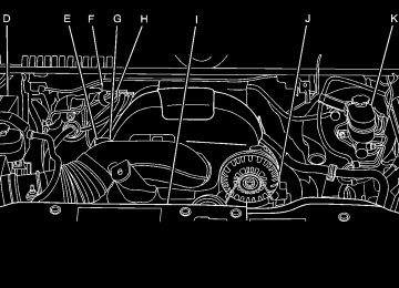
Engine Compartment Overview If the vehicle has a diesel engine and/or an Allison Transmission, see the maintenance schedule section in the DURAMAX® Diesel manual.
5.3 L V8 Engine (4.3 L V6 Engine, 4.8 L V6 Engine, 6.0 L V8 Engine and 6.2 L V8 Engine similar):
6-16
A. Engine Air Cleaner/Filter on page 6‑21. B. Coolant Surge Tank and Pressure Cap. See
Cooling System on page 6‑30.
C. Positive (+) Terminal. See Jump Starting on
page 6‑44 .
D. Battery on page 6‑43. E. Engine Oil Fill Cap. See “When to Add Engine Oil”
under Engine Oil on page 6‑18.
F. Automatic Transmission Dipstick. See “Checking
the Fluid Level” under Automatic Transmission Fluid (4-Speed Transmission) on page 6‑23 or Automatic Transmission Fluid (6-Speed Transmission) on page 6‑26.
G. Remote Negative (−) Terminal (Out of View). See
Jump Starting on page 6‑44.
H. Engine Oil Dipstick (Out of View). See “Checking
Engine Oil” under Engine Oil on page 6‑18.
I. Engine Cooling Fan. See Cooling System on
page 6‑30 .
J. Power Steering Fluid Reservoir. See Power
Steering Fluid on page 6‑37.
K. Brake Master Cylinder Reservoir. See “Brake
Fluid” under Brakes on page 6‑39.
L. Underhood Fuse Block on page 6‑122. M. Windshield Washer Fluid Reservoir. See “Adding Washer Fluid” under Windshield Washer Fluid on page 6‑38 .
6-17
Engine Oil For diesel engine vehicles, see “Engine Oil” in the DURAMAX® Diesel manual. Checking Engine Oil It is a good idea to check the engine oil level at each fuel fill. In order to get an accurate reading, the oil must be warm and the vehicle must be on level ground. The engine oil dipstick handle is a yellow loop. See Engine Compartment Overview on page 6‑16 for the location of the engine oil dipstick.
1. Turn off the engine and give the oil several minutes to drain back into the oil pan. If this is not done, the oil dipstick might not show the actual level.
2. Pull out the dipstick and clean it with a paper towel or cloth, then push it back in all the way. Remove it again, keeping the tip down, and check the level.
When to Add Engine Oil
If the oil is below the cross-hatched area at the tip of the dipstick, add at least one liter/quart of the recommended oil. This section explains what kind of oil to use. For engine oil crankcase capacity, see Capacities and Specifications on page 6‑126. Notice: Do not add too much oil. If the engine has so much oil that the oil level gets above the cross-hatched area that shows the proper operating range, the engine could be damaged.
6-18
See Engine Compartment Overview on page 6‑16
for the location of the engine oil fill cap.. American Petroleum Institute (API) starburst
symbol
Oils meeting these requirements should have the starburst symbol on the container. This symbol indicates that the oil has been certified by the American Petroleum Institute (API).
Add enough oil to put the level somewhere in the proper operating range. Push the dipstick all the way back in when through. What Kind of Engine Oil to Use Look for three things:
. GM6094M
Use only an oil that meets GM Standard GM6094M. . SAE 5W-30
SAE 5W-30 is best for the vehicle. These numbers on an oil container show its viscosity, or thickness. Do not use other viscosity oils such as SAE 20W-50.
Notice: Use only engine oil identified as meeting GM Standard GM6094M and showing the American Petroleum Institute Certified For Gasoline Engines starburst symbol. Failure to use the recommended oil can result in engine damage not covered by the vehicle warranty. Cold Temperature Operation If in an area of extreme cold, where the temperature falls below −29°C (−20°F), use either an SAE 5W-30
synthetic oil or an SAE 0W-30 engine oil. Both provide easier cold starting for the engine at extremely low temperatures. Always use an oil that meets the required specification, GM6094M. See “What Kind of Engine Oil to Use” for more information.6-19
Engine Oil Additives / Engine Oil Flushes Do not add anything to the oil. The recommended oils with the starburst symbol that meet GM Standard GM6094M are all that is needed for good performance and engine protection. Engine oil system flushes are not recommended and could cause engine damage not covered by the vehicle warranty. Engine Oil Life System When to Change Engine Oil This vehicle has a computer system that indicates when to change the engine oil and filter. This is based on engine revolutions and engine temperature, and not on mileage. Based on driving conditions, the mileage at which an oil change is indicated can vary considerably. For the oil life system to work properly, the system must be reset every time the oil is changed. On some vehicles, when the system has calculated that oil life has been diminished, a CHANGE ENGINE OIL SOON message comes on to indicate that an oil change is necessary. See DIC Warnings and Messages on page 4‑63 . Change the oil as soon as possible within the next 1 000 km (600 miles). It is possible that,
6-20
if driving under the best conditions, the oil life system might not indicate that an oil change is necessary for over a year. However, the engine oil and filter must be changed at least once a year and at this time the system must be reset. For vehicles without the CHANGE ENGINE OIL SOON message, An oil change is needed when the OIL LIFE REMAINING percentage is near 0%. Your dealer/retailer has trained service people who will perform this work using genuine parts and reset the system. It is also important to check the oil regularly and keep it at the proper level. If the system is ever reset accidentally, the oil must be changed at 5 000 km (3,000 miles) since the last oil change. Remember to reset the oil life system whenever the oil is changed. How to Reset the Engine Oil Life System The Engine Oil Life System calculates when to change the engine oil and filter based on vehicle use. Whenever the oil is changed, reset the system so it can calculate when the next oil change is required. If a situation occurs where the oil is changed prior to a CHANGE ENGINE OIL SOON message coming on, reset the system.
Always reset the engine oil life to 100% after every oil change. It will not reset itself. To reset the Engine Oil Life System on most vehicles:
1. Display the OIL LIFE REMAINING on the DIC.
If the vehicle does not have DIC buttons, the vehicle must be in P (Park) to access this display. See DIC Operation and Displays (With DIC Buttons) on page 4‑49 or DIC Operation and Displays (Without DIC Buttons) on page 4‑56.
2. Press and hold the SET/RESET button on the DIC,
or the trip odometer reset stem if the vehicle does not have DIC buttons, for more than five seconds. The oil life will change to 100%.
On all vehicles, the Engine Oil Life System can be reset as follows:
1. Turn the ignition to ON/RUN with the engine off 2. Fully press the accelerator pedal slowly three times
within five seconds.
3. Display the OIL LIFE REMAINING on the DIC. If the display shows 100%, the system is reset. See DIC Operation and Displays (With DIC Buttons) on page 4‑49 or DIC Operation and Displays (Without DIC Buttons) on page 4‑56.
If the vehicle has a CHANGE ENGINE OIL SOON message and it comes back on when the vehicle is started and/or the OIL LIFE REMAINING is near 0%, the Engine Oil Life System has not reset. Repeat the procedure. What to Do with Used Oil Used engine oil contains certain elements that can be unhealthy for your skin and could even cause cancer. Do not let used oil stay on your skin for very long. Clean your skin and nails with soap and water, or a good hand cleaner. Wash or properly dispose of clothing or rags containing used engine oil. See the manufacturer's warnings about the use and disposal of oil products. Used oil can be a threat to the environment. If you change your own oil, be sure to drain all the oil from the filter before disposal. Never dispose of oil by putting it in the trash, pouring it on the ground, into sewers, or into streams or bodies of water. Recycle it by taking it to a place that collects used oil. Engine Air Cleaner/Filter If the vehicle has a diesel engine, see “Pickup Models” under “Engine Air Cleaner/Filter” in the DURAMAX® Diesel Supplement for the correct inspection and replacement procedures. See Engine Compartment Overview on page 6‑16 for the location of the engine air cleaner/filter.
6-21
Replacing the Engine Air Cleaner/Filter
1. Locate the air cleaner/filter assembly . See Engine
Compartment Overview on page 6‑16.
2. Loosen the four screws on the cover of the
housing and lift up the cover.
When to Inspect the Engine Air Cleaner/ Filter Inspect the air cleaner/filter at the Maintenance II intervals and replace it at the first oil change after each 50,000 mile (80 000 km) interval. See Scheduled Maintenance on page 7‑3 for more information. If driving on dusty/dirty conditions, inspect the filter at each engine oil change. How to Inspect the Engine Air Cleaner/ Filter To inspect the air cleaner/filter, remove the engine