- 2001 Chevrolet Silverado Owners Manuals
- Chevrolet Silverado Owners Manuals
- 2013 Chevrolet Silverado Owners Manuals
- Chevrolet Silverado Owners Manuals
- 2015 Chevrolet Silverado Owners Manuals
- Chevrolet Silverado Owners Manuals
- 2016 Chevrolet Silverado Owners Manuals
- Chevrolet Silverado Owners Manuals
- 2010 Chevrolet Silverado Owners Manuals
- Chevrolet Silverado Owners Manuals
- 2012 Chevrolet Silverado Owners Manuals
- Chevrolet Silverado Owners Manuals
- 2004 Chevrolet Silverado Owners Manuals
- Chevrolet Silverado Owners Manuals
- 2008 Chevrolet Silverado Owners Manuals
- Chevrolet Silverado Owners Manuals
- 2014 Chevrolet Silverado Owners Manuals
- Chevrolet Silverado Owners Manuals
- 2000 Chevrolet Silverado Owners Manuals
- Chevrolet Silverado Owners Manuals
- 2011 Chevrolet Silverado Owners Manuals
- Chevrolet Silverado Owners Manuals
- 2003 Chevrolet Silverado Owners Manuals
- Chevrolet Silverado Owners Manuals
- 2007 Chevrolet Silverado Owners Manuals
- Chevrolet Silverado Owners Manuals
- 2005 Chevrolet Silverado Owners Manuals
- Chevrolet Silverado Owners Manuals
- Download PDF Manual
-
into R (Reverse), the video image automatically appears on the navigation screen. Once the driver shifts out of R (Reverse), the navigation screen will go back to the last screen that had been displayed, after a delay. Turning the Rear Vision Camera System On or Off To turn the rear vision camera system on or off:
1. Shift into P (Park). 2. Press the MENU button to enter the configure
menu options, then press the MENU hard key to select Display or touch the Display screen button.
3. Select the Rear Camera Options screen button.
The Rear Camera Options screen will display.
3-64
4. Select the Video screen button. When the Video
screen button is highlighted the RVC system is on.
The delay that is received after shifting out of R (Reverse) is approximately 10 seconds. The delay can be cancelled by performing one of the following: . Pressing a hard key on the navigation system. . Shifting in to P (Park). . Reach a vehicle speed of 5 mph (8 km/h).
There is a message on the rear vision camera screen that states “Check Surroundings for Safety”.
Adjusting the Brightness and Contrast of the Screen To adjust the brightness and contrast of the screen, press the MENU button while the rear vision camera image is on the display. Any adjustments made will only affect the rear vision camera screen. ] (Brightness) : Touch the + (plus) or – (minus) screen buttons to increase or decrease the brightness of the screen. _ (Contrast) : Touch the + (plus) or – (minus) screen buttons to increase or decrease the contrast of the screen. Symbols The navigation system may have a feature that lets the driver view symbols on the navigation screen while using the rear vision camera. The Ultrasonic Rear Park Assist (URPA) system must not be disabled to use the caution symbols. If URPA has been disabled and the symbols have been turned on, the Rear Parking Assist Symbols Unavailable error message may display. See Ultrasonic Rear Parking Assist (URPA) on page 3‑60.
The symbols appear when an object has been detected by the URPA system. The symbol may cover the object when viewing the navigation screen. To turn the symbols on or off:
1. Make sure that URPA has not been disabled. 2. Shift into P (Park). 3. Press the MENU hard key to enter the configure
menu options, then press the MENU hard key repeatedly until Display is selected or touch the Display screen button.
4. Select the Rear Camera Options screen button.
The Rear Camera Options screen will display. 5. Touch the Symbols screen button. The screen
button will be highlighted when on.
Rear Vision Camera Error Messages Service Rear Vision Camera System : This message can display when the system is not receiving information it requires from other vehicle systems. If any other problem occurs or if a problem persists, see your dealer/retailer.
3-65
Rear Vision Camera Location
The following illustration shows the field of view that the camera provides.
The image is provided by the camera located in the bezel for the tailgate handle. The camera uses a special lens. The distance of the image that appears on the screen differs from the actual distance. The area displayed by the camera is limited. The camera does not display objects which are close to either corner of the bumper or under the bumper. The area displayed on the screen can vary according to vehicle orientation or road conditions.
3-66
A. View displayed by the camera. B. Corner of the rear bumper.
Disconnecting the Rear Vision Camera To disconnect the camera:
1. Remove the license plate. 2. Disconnect the camera connectors from the
chassis harness, located behind the license plate, by pressing on the release tab on each connector.
A. Chassis harness connector B. Release tab C. Camera connector
3. Plug the two exposed chassis harness connectors
together to prevent contamination.
A. Chassis harness connector B. Release tab
4. Feed the wiring harness through the pickup box,
then plug the camara connectors together to prevent contamination.
5. Remove the tailgate. See Tailgate on page 3‑12
for more information.
6. Re‐install the license plate.
Reverse this procedure to reinstall the rear vision camera and make sure the grommet and connection is secure.
3-67
When the System Does Not Seem To Work Properly The rear vision camera system might not work properly or display a clear image if:
The RVC is turned off. See “Turning the Rear Camera System On or Off” earlier in this section. It is dark. The sun or the beam of headlights is shining directly into the camera lens. Ice, snow, mud, or anything else builds up on the camera lens. Clean the lens, rinse it with water, and wipe it with a soft cloth. The back of the vehicle is in an accident, the position and mounting angle of the camera can change or the camera can be affected. Be sure to have the camera and its position and mounting angle checked at your dealer/retailer.
The rear vision camera system display in the rearview mirror may turn off or not appear as expected due to one of the following conditions. If this occurs the left indicator light on the mirror will flash.
. A slow flash may indicate a loss of video signal,
or no video signal present during the reverse cycle. . A fast flash may indicate that the display has been
on for the maximum allowable time during a reverse cycle, or the display has reached an Over Temperature limit. The fast flash conditions are used to protect the video device from high temperature conditions. Once conditions return to normal the device will reset and the green indicator will stop flashing.
During any of these fault conditions, the display will be blank and the indicator will continue to flash as long as the vehicle is in R (Reverse) or until the conditions return to normal. Pressing and holding z when the left indicator light is flashing will turn off the video display along with the left indicator light.
3-68
Universal Home Remote System See Radio Frequency Statement on page 8‑18 for information regarding Part 15 of the Federal Communications Commission (FCC) Rules and RSS-210/211 of Industry and Science Canada. Universal Home Remote System Operation (With Three Round LED)
This vehicle may have the Universal Home Remote System. If there are three round Light Emitting Diode (LED) indicator lights above the Universal Home Remote buttons, follow the instructions below.
This system provides a way to replace up to three remote control transmitters used to activate devices such as garage door openers, security systems, and home automation devices. Do not use this system with any garage door opener that does not have the stop and reverse feature. This includes any garage door opener model manufactured before April 1, 1982. Read the instructions completely before attempting to program the transmitter. Because of the steps involved, it may be helpful to have another person assist with programming the transmitter. Be sure to keep the original remote control transmitter for use in other vehicles, as well as, for future programming. Only the original remote control transmitter is needed for Fixed Code programming. The programmed buttons should be erased when the vehicle is sold or the lease ends. See “Erasing Universal Home Remote Buttons” later in this section. Park the vehicle outside of the garage when programming a garage door. Be sure that people and objects are clear of the garage door or gate that is being programmed.
3-69
Programming Universal Home Remote — Rolling Code For questions or help programming the Universal Home Remote System, call 1-866-572-2728 or go to learcar2u.com. Most garage door openers sold after 1996 are Rolling Code units. Programming a garage door opener involves time-sensitive actions, so read the entire procedure before starting. Otherwise, the device will time out and the procedure will have to be repeated. To program up to three devices:
1. From inside the vehicle, press the two outside
buttons at the same time for one to two seconds, and immediately release them.
3-70
2. Locate in the garage, the garage door opener
receiver (motor-head unit). Locate the “Learn” or “Smart” button. It can usually be found where the hanging antenna wire is attached to the motor-head unit and may be a colored button. Press this button. After pressing this button, complete the following steps in less than 30 seconds.
3.
Immediately return to the vehicle. Press and hold the Universal Home Remote button that will be used to control the garage door until the garage door moves. The indicator light, above the selected button, should slowly blink. This button may need to be held for up to 20 seconds. Immediately, within one second, release the button when the garage door moves. The indicator light will blink rapidly until programming is complete. 5. Press and release the same button again. The
4.
garage door should move, confirming that programming is successful and complete.
To program another Rolling Code device such as an additional garage door opener, a security device, or home automation device, repeat Steps 1 through 5, choosing a different function button in Step 3 than what was used for the garage door opener.
If these instructions do not work, the garage door opener is probably a Fixed Code unit. Follow the Programming instructions that follow for a Fixed Code garage door opener. Programming Universal Home Remote — Fixed Code For questions or help programming the Universal Home Remote System, call 1-866-572-2728 or go to learcar2u.com. Most garage door openers sold before 1996 are Fixed Code units. Programming a garage door opener involves time-sensitive actions, so read the entire procedure before starting. Otherwise, the device will time out and the procedure will have to be repeated.
3-71
To program up to three devices:
The garage door opener receiver (motor head unit) could also have a row of dip switches that can be used when programming the Universal Home Remote. If the total number of switches on the motor head and hand held transmitter are different, or if the dip switch settings are different, use the dip switch settings on the motor head unit to program the Universal Home Remote. The motor head dip switch settings can also be used when the original hand held transmitter is not available.
1. To verify that the garage door opener is a Fixed Code unit, remove the battery cover on the hand held transmitter supplied by the manufacturer of the garage door opener motor. If there are a row of dip switches similar to the graphic above, the garage door opener is a Fixed Code unit. If you do not see a row of dip switches, return to the previous section for Programming Universal Home Remote – Rolling Code. Your hand held transmitter can have between eight to 12 dip switches depending on the brand of transmitter.
3-72
Example of Eight Dip Switches with Two Positions
2. Write down the eight to 12 switch settings from left
to right as follows: . When a switch is in the up position, write “Left.” . When a switch is in the down position, write
“Right.” If a switch is set between the up and down position, write “Middle.” The switch settings written down in Step 2 now become the button strokes to be entered into the Universal Home Remote in Step 4. Be sure to enter the switch settings written down in Step 2, in order from left to right, into the Universal Home Remote, when completing Step 4.
3. From inside your vehicle, first firmly press all three buttons at the same time for about three seconds. Release the buttons to put the Universal Home Remote into programming mode.
3-73
Example of Eight Dip Switches with Three Positions The panel of switches might not appear exactly as they do in the examples above, but they should be similar. The switch positions on the hand-held transmitter could be labeled, as follows: . A switch in the up position could be labeled as
“Up,” “+,” or “On.”
. A switch in the down position could be labeled
as “Down,” “−,” or “Off.”
. A switch in the middle position could be labeled
as “Middle,” “0,” or “Neutral.”
5. After entering all of the switch positions, again, firmly press and release all three buttons at the same time. The indicator lights will turn on.
6. Press and hold the button that will be used to control the garage door until the garage door moves. The indicator light above the selected button should slowly blink. This button may need to be held for up to 55 seconds. Immediately release the button when the garage door moves. The indicator light will blink rapidly until programming is complete.
7.
8. Press and release the same button again. The
garage door should move, confirming that programming is successful and complete.
To program another Fixed Code device such as an additional garage door opener, a security device, or home automation device, repeat Steps 1-8, choosing a different button in Step 6 than what was used for the garage door opener. Using Universal Home Remote Press and hold the appropriate button for at least half of a second. The indicator light will come on while the signal is being transmitted.
4. The indicator lights will blink slowly. Enter each
switch setting from Step 2 into your vehicle's Universal Home Remote. You will have two and one-half minutes to complete Step 4. Now press one button on the Universal Home Remote for each switch setting as follows:
If you wrote “Left,” press the left button in the vehicle. If you wrote “Right,” press the right button in the vehicle. If you wrote “Middle,” press the middle button in the vehicle.
3-74
Storage Areas
Glove Box Lift up on the glove box lever to open it. Cupholders Vehicles with cupholders have them located on and behind the center console and in the rear seat armrest. Pull the loop down on the rear seat armrest to access the cupholders. Pull downward on the cover to access the cupholders behind the center console.
Reprogramming Universal Home Remote Buttons Any of the three buttons can be reprogrammed by repeating the instructions. Erasing Universal Home Remote Buttons The programmed buttons should be erased when the vehicle is sold or the lease ends. To erase either Rolling Code or Fixed Code on the Universal Home Remote device:
1. Press and hold the two outside buttons at the
same time for approximately 20 seconds, until the indicator lights, located directly above the buttons, begin to blink rapidly.
2. Once the indicator lights begin to blink, release both buttons. The codes from all buttons will be erased.
For help or information on the Universal Home Remote System, call the customer assistance phone number under Customer Assistance Offices on page 8‑6.
3-75
Instrument Panel Storage For vehicles equipped with an instrument panel storage area, it is located above the glove box.
Center Console Storage Vehicles with an upper and lower center console storage area have cupholders included.
Access the storage area by pressing and holding in the driver side of the handle and pull out on the exposed portion of the handle.
Pull the lever (A) up to access the upper storage area. Raise the upper storage bin, then pull the lever (B) up to access the lower storage area. Use the key to lock and unlock the lower storage area.
3-76
Roof Rack System
{ WARNING:
If something is carried on top of the vehicle that is longer or wider than the roof rack— like paneling, plywood, or a mattress— the wind can catch it while the vehicle is being driven. The item being carried could be violently torn off, and this could cause a collision, and damage the vehicle. Never carry something longer or wider than the roof rack on top of the vehicle unless using a GM Certified accessory carrier.
For vehicles with a roof rack, the rack can be used to load items. For roof racks that do not have crossrails included, GM Certified crossrails can be purchased as an accessory. See your dealer/retailer for additional information. Notice: Loading cargo on the roof rack that weighs more than 91 kg (200 lbs) or hangs over the rear or sides of the vehicle may damage the vehicle. Load cargo so that it rests evenly between the crossrails, making sure to fasten cargo securely.
To prevent damage or loss of cargo when driving, check to make sure crossrails and cargo are securely fastened. Loading cargo on the roof rack will make the vehicle’s center of gravity higher. Avoid high speeds, sudden starts, sharp turns, sudden braking or abrupt maneuvers, otherwise it may result in loss of control. If driving for a long distance, on rough roads, or at high speeds, occasionally stop the vehicle to make sure the cargo remains in its place. Do not exceed the maximum vehicle capacity when loading the vehicle. For more information on vehicle capacity and loading, see Loading the Vehicle on page 5‑29 .
If small heavy objects are placed on the roof, cut a piece of 3/8 inch plywood to fit inside the crossrails and siderails to spread the load. Tie the plywood to the siderail supports. Tie the load and secure it to the crossrails or the siderail supports. Use the crossrails only to keep the load from sliding. To move a crossrail, lift the release lever up, on both sides of the rail. Then slide the crossrail to the desired position balancing the force side to side. Press the release lever down on both sides of the rail, down to tighten it. Try to slide the crossrail back and forth slightly to make sure it is tight.
3-77
.
To carry long items, move the crossrails as far apart as possible. Tie the load to the crossrails and the siderails or siderail supports. Also tie the load to the bumpers, but do not tie the load so tightly that the crossrails or siderails are damaged.
. After moving a crossrail, be sure it is securely
locked into the siderail.
A Center High-Mounted Stoplamp (CHMSL) is located above the rear window glass. Make sure items loaded on the roof of the vehicle do not block or damage the CHMSL. Rear Seat Armrest Vehicles with a rear seat armrest have two cupholders. Pull the armrest down from the rear seatback to access the cupholders. Cargo Management System For vehicles with a cargo management system, it is located in the bed of the truck. The system contains three rails located on the front and sides of the bed. The system has four adjustable cargo tie-downs, that can be placed on the upper and lower slides of the rail.
3-78
To adjust a tie-down, pull the locator pin out and move the tie-down to another location making sure the locator pin lines up with a locator hole on the rail. The tie-down pin may not be installed correctly if the pin does not line up, turn it over and reinstall. The tie-down will not move when the pin is completely installed. The maximum load for each rail is 500 lbs (227 kg). The rails are notched at each end which allows the tie-downs to be removed and placed on another rail. To remove, pull the locator pin out and slide the tie-down to the end of the rail and pull back.
To remove or install cargo tie-downs at the front of the bed, slide the corner cap towards the center of the bed to expose the rail notches. To remove the corner cap, pull either edge away from the rail. To remove the system, loosen the toggle bolts on each rail until they can be removed from the bed of the truck. To replace the system, place the toggle bolts and rails into their original locations and tighten them to a torque setting of 12.5 ft lbs (17 Y). If the system is removed to install a bed liner, make sure there is no bed liner material in the installation points. Notice: If cargo is tied down using the horizontal slots on the top of the pickup box, the box could be damaged. Using the horizontal slots on the top of the pickup box for tie-down locations may cause damage to the pickup box and would not be covered by the vehicle warranty. Only use the tie-down loops if the vehicle does not have the cargo management system.
Sunroof On vehicle with a power sliding sunroof, the ignition needs to be turned to RUN, or the Retained Accessory Power (RAP) must be activated to open or close the sunroof. When RAP is active, the sunroof will work for 10 minutes after the ignition is turned off, or until the driver's door is opened. See Retained Accessory Power (RAP) on page 3‑23 for more information. Do not leave the sunroof open for long periods of time while the vehicle is not in use. Debris can collect in the tracks and damage the sunroof operation and plug the water draining system. Extended Cab
If your vehicle is an extended cab, the sunroof switch is located on the headliner above the rearview mirror.
3-79
Crew Cab
If your vehicle is a crew cab, there are two sunroof switches located in the overhead console above the rearview mirror.
Vent : From the closed position, press the rear of the passenger's side switch to vent the sunroof. To close the sunroof, press and hold the front of the passenger's side switch.
Vent : From the closed position, press and hold the rear of the switch to vent the sunroof. To close the sunroof, press and hold the front of the switch. Open : From the vent position, the sunroof can be fully opened either manually or by using the express-open feature. To open manually, press the rear of the switch to the first depression and hold until the sunroof has reached the desired position. To open using express-open, press the rear of the switch fully and release. The sunroof will move to the full open position. To stop the sunroof partway, press the switch a second time. Close : From the vent, or open position, press and hold the front of the switch to close the sunroof. The sunroof also has a roller sunshade that can be used to block the rays of the sun. The roller sunshade can be manually operated with the sunroof in an open or closed position. To open the sunshade, press and unlatch it, and roll it back. To close, pull it forward and latch it into the closed position. When the sunroof is opened, an air deflector will automatically raise. The air deflector will retract when the sunroof is closed.
3-80
Manual-Open/Manual-Close : To open the sunroof press and hold the rear of the driver's side switch until the sunroof reaches the desired position. To close the sunroof, press and hold the front of the driver's side switch until the sunroof reaches the desired position. When the sunroof is opened, an air deflector will automatically raise. The air deflector will retract when the sunroof is closed. Express-Open/Express-Close : To express-open the sunroof, fully press and release the rear of the driver's side switch. The sunroof will open automatically. To stop the sunroof partway, press the switch a second time. To express-close the sunroof, fully press and release the front of the driver's side switch. The sunroof will close automatically. To stop the sunroof partway, press the switch a second time. The sunroof also has a sunshade which you can pull forward to block sun rays. The sunshade must be opened and closed manually.
Anti-Pinch Feature (Crew Cab Only) : If an object is in the path of the sunroof while it is closing, the anti-pinch feature will detect the object and stop the sunroof from closing at the point of the obstruction. The sunroof will then open halfway, and the air deflector will raise. To close the sunroof once it has re-opened, refer to the Express-Close or Manual-Close functions described previously. If the sunroof is in the vent position, and there is an object in the path of the sunroof when it closing, the anti-pinch feature will detect the object and stop the sunroof. To close the sunroof once it has stopped, refer to the Vent functions described previously.
3-81
2 NOTES
3-82
Section 4
Instrument Panel
Instrument Panel Overview . . . . . . . . . . . . . . . . . . . . . . . . 4-3
Hazard Warning Flashers . . . . . . . . . . . . . . . . . . . . . . . 4-3
Horn . . . . . . . . . . . . . . . . . . . . . . . . . . . . . . . . . . . . . . . . . . . . 4-3
Tilt Wheel . . . . . . . . . . . . . . . . . . . . . . . . . . . . . . . . . . . . . . . 4-3
Turn Signal/Multifunction Lever . . . . . . . . . . . . . . . . . . 4-4
Turn and Lane-Change Signals . . . . . . . . . . . . . . . . . 4-4
Headlamp High/Low-Beam Changer . . . . . . . . . . . . 4-5
Flash-to-Pass . . . . . . . . . . . . . . . . . . . . . . . . . . . . . . . . . . . 4-5
Windshield Wipers . . . . . . . . . . . . . . . . . . . . . . . . . . . . . . 4-6
Windshield Washer . . . . . . . . . . . . . . . . . . . . . . . . . . . . . 4-6
Cruise Control . . . . . . . . . . . . . . . . . . . . . . . . . . . . . . . . . . 4-7
Exterior Lamps . . . . . . . . . . . . . . . . . . . . . . . . . . . . . . . . 4-10
Headlamps on Reminder . . . . . . . . . . . . . . . . . . . . . . . 4-11
Daytime Running Lamps (DRL) . . . . . . . . . . . . . . . . 4-12
Automatic Headlamp System . . . . . . . . . . . . . . . . . . 4-12
Puddle Lamps . . . . . . . . . . . . . . . . . . . . . . . . . . . . . . . . . 4-13
Fog Lamps . . . . . . . . . . . . . . . . . . . . . . . . . . . . . . . . . . . . 4-13
Auxiliary Roof-Mounted Lamp . . . . . . . . . . . . . . . . . 4-14
Instrument Panel Brightness . . . . . . . . . . . . . . . . . . . 4-14
Dome Lamps . . . . . . . . . . . . . . . . . . . . . . . . . . . . . . . . . . 4-14
Dome Lamp Override . . . . . . . . . . . . . . . . . . . . . . . . . . 4-15
Entry Lighting . . . . . . . . . . . . . . . . . . . . . . . . . . . . . . . . . . 4-15
Exit Lighting . . . . . . . . . . . . . . . . . . . . . . . . . . . . . . . . . . . 4-15
Reading Lamps . . . . . . . . . . . . . . . . . . . . . . . . . . . . . . . . 4-15Cargo Lamp . . . . . . . . . . . . . . . . . . . . . . . . . . . . . . . . . . . 4-15
Electric Power Management . . . . . . . . . . . . . . . . . . . 4-16
Battery Run-Down Protection . . . . . . . . . . . . . . . . . . 4-16
Accessory Power Outlet(s) . . . . . . . . . . . . . . . . . . . . . 4-17
Ashtray(s) and Cigarette Lighter . . . . . . . . . . . . . . . 4-18
Climate Controls . . . . . . . . . . . . . . . . . . . . . . . . . . . . . . . . . . 4-18Climate Control System
(With Air Conditioning) . . . . . . . . . . . . . . . . . . . . . . . 4-18
Climate Control System (With Heater Only) . . . . 4-21
Dual Automatic Climate Control System . . . . . . . 4-22
Outlet Adjustment . . . . . . . . . . . . . . . . . . . . . . . . . . . . . . 4-28
Warning Lights, Gages, and Indicators . . . . . . . . . . 4-28
Instrument Panel Cluster . . . . . . . . . . . . . . . . . . . . . . . 4-29
Speedometer and Odometer . . . . . . . . . . . . . . . . . . . 4-30
Trip Odometer . . . . . . . . . . . . . . . . . . . . . . . . . . . . . . . . . 4-30
Tachometer . . . . . . . . . . . . . . . . . . . . . . . . . . . . . . . . . . . . 4-30
Safety Belt Reminders . . . . . . . . . . . . . . . . . . . . . . . . . 4-31
Airbag Readiness Light . . . . . . . . . . . . . . . . . . . . . . . . 4-32
Airbag Off Light . . . . . . . . . . . . . . . . . . . . . . . . . . . . . . . . 4-32
Passenger Airbag Status Indicator . . . . . . . . . . . . . 4-34
Charging System Light . . . . . . . . . . . . . . . . . . . . . . . . 4-36
Voltmeter Gage . . . . . . . . . . . . . . . . . . . . . . . . . . . . . . . . 4-36
Brake System Warning Light . . . . . . . . . . . . . . . . . . . 4-37
Antilock Brake System (ABS) Warning Light . . . 4-384-1
Section 4
Instrument Panel
Audio System(s) . . . . . . . . . . . . . . . . . . . . . . . . . . . . . . . . . . 4-82
Setting the Clock . . . . . . . . . . . . . . . . . . . . . . . . . . . . . . 4-82
Radio(s) . . . . . . . . . . . . . . . . . . . . . . . . . . . . . . . . . . . . . . . 4-85
Using an MP3 (Radios with CD) . . . . . . . . . . . . . . 4-105
Using an MP3 (Radios with CD and DVD) . . . . 4-112
XM Radio Messages . . . . . . . . . . . . . . . . . . . . . . . . . 4-120
Navigation/Radio System . . . . . . . . . . . . . . . . . . . . . 4-121
Bluetooth® . . . . . . . . . . . . . . . . . . . . . . . . . . . . . . . . . . . . 4-121
Rear Seat Entertainment (RSE) System . . . . . . 4-132
Rear Seat Audio (RSA) . . . . . . . . . . . . . . . . . . . . . . . 4-141
Theft-Deterrent Feature . . . . . . . . . . . . . . . . . . . . . . 4-143
Audio Steering Wheel Controls . . . . . . . . . . . . . . . 4-143
Radio Reception . . . . . . . . . . . . . . . . . . . . . . . . . . . . . . 4-146
Fixed Mast Antenna . . . . . . . . . . . . . . . . . . . . . . . . . . 4-147
XM™ Satellite Radio Antenna System . . . . . . . . 4-147StabiliTrak® Indicator Light . . . . . . . . . . . . . . . . . . . . . 4-39
Engine Coolant Temperature Gage . . . . . . . . . . . . 4-40
Tire Pressure Light . . . . . . . . . . . . . . . . . . . . . . . . . . . . 4-40
Malfunction Indicator Lamp . . . . . . . . . . . . . . . . . . . . 4-41
Oil Pressure Gage . . . . . . . . . . . . . . . . . . . . . . . . . . . . . 4-44
Oil Pressure Light . . . . . . . . . . . . . . . . . . . . . . . . . . . . . 4-45
Security Light . . . . . . . . . . . . . . . . . . . . . . . . . . . . . . . . . . 4-46
Fog Lamp Light . . . . . . . . . . . . . . . . . . . . . . . . . . . . . . . . 4-46
Cruise Control Light . . . . . . . . . . . . . . . . . . . . . . . . . . . 4-46
Highbeam On Light . . . . . . . . . . . . . . . . . . . . . . . . . . . . 4-46
Four-Wheel-Drive Light . . . . . . . . . . . . . . . . . . . . . . . . 4-47
Tow/Haul Mode Light . . . . . . . . . . . . . . . . . . . . . . . . . . 4-47
Fuel Gage . . . . . . . . . . . . . . . . . . . . . . . . . . . . . . . . . . . . . 4-47
Low Fuel Warning Light . . . . . . . . . . . . . . . . . . . . . . . . 4-48
Driver Information Center (DIC) . . . . . . . . . . . . . . . . . . 4-49DIC Operation and Displays
(With DIC Buttons) . . . . . . . . . . . . . . . . . . . . . . . . . . 4-49
DIC Operation and Displays
(Without DIC Buttons) . . . . . . . . . . . . . . . . . . . . . . . 4-56
DIC Compass . . . . . . . . . . . . . . . . . . . . . . . . . . . . . . . . . . 4-60
DIC Warnings and Messages . . . . . . . . . . . . . . . . . . 4-63
DIC Vehicle Customization(With DIC Buttons) . . . . . . . . . . . . . . . . . . . . . . . . . . 4-73
4-2
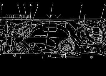
Instrument Panel Overview
Tilt Wheel
Hazard Warning Flashers | (Hazard Warning Flasher): Press this button located on top of the steering column, to make the front and rear turn signal lamps flash on and off. This warns others that you are having trouble. Press again to turn the flashers off. When the hazard warning flashers are on, the vehicle's turn signals will not work. Horn To sound the horn, press the horn symbols located on the steering wheel.
The tilt lever is located on the lower left side of the steering column. To adjust the steering wheel:
1. Hold the steering wheel and pull the lever. 2. Move the steering wheel to a comfortable position. 3. Release the lever to lock the wheel in place.
Do not adjust the steering wheel while driving.
4-3
Turn Signal/Multifunction Lever
Turn and Lane-Change Signals
An arrow on the instrument panel cluster flashes in the direction of the turn or lane change.
Move the lever all the way up or down to signal a turn. Raise or lower the lever for less than one second until the arrow starts to flash to signal a lane change. This causes the turn signals to automatically flash three times. It will flash six times if tow-haul mode is active. Holding the turn signal lever for more than one second will cause the turn signals to flash until you release the lever. The lever returns to its starting position whenever it is released. If after signaling a turn or a lane change the arrows flash rapidly or do not come on, a signal bulb could be burned out. Have the bulbs replaced. If the bulb is not burned out, check the fuse. See Fuses and Circuit Breakers on page 6‑118.
The lever on the left side of the steering column includes the following: G : Turn and Lane Change Signals 5 3 : Headlamp High/Low-Beam Changer N : Windshield Wipers L : Windshield Washer Flash-to-Pass. Exterior Lamps. Information for these features is on the pages following.
4-4
Turn Signal On Chime If the turn signal is left on for more than 3/4 of a mile (1.2 km), a chime sounds at each flash of the turn signal, if the vehicle has a radio. The message TURN SIGNAL ON will also appear in the Driver Information Control (DIC). To turn the chime and message off, move the turn signal lever to the off position. Headlamp High/Low-Beam Changer 53 (Headlamp High/Low Beam Changer) : To change the headlamps from low to high beam, push the lever toward the instrument panel. To return to low-beam headlamps, pull the multifunction lever toward you. Then release it.
Flash-to-Pass This feature lets you use the high-beam headlamps to signal a driver in front of you that you want to pass. It works even if the headlamps are in the automatic position. To use it, pull the turn signal lever toward you, then release it. If the headlamps are in the automatic position or on low beam, the high-beam headlamps will turn on. They will stay on as long as you hold the lever toward you. The high-beam indicator on the instrument panel cluster will come on. Release the lever to return to normal operation.
When the high beams are on, this indicator light on the instrument panel cluster will also be on.
4-5
Windshield Wipers
Turn the band with the wiper symbol to control the windshield wipers. 8 (Mist): Single wipe, turn to 8, then release. Several wipes, hold the band on 8 longer. 9 (Off): Turns the windshield wipers off. 6 (Adjustable Interval Wipes): Turn the band up for more frequent wipes or down for less frequent wipes. 6 (Low Speed): Slow wipes. ? (High Speed): Fast wipes.
4-6
Clear ice and snow from the wiper blades before using them. If frozen to the windshield, carefully loosen or thaw them. Damaged wiper blades should be replaced. See Windshield Wiper Blade Replacement on page 6‑63 . Heavy snow or ice can overload the wiper motor. A circuit breaker will stop the motor until it cools down. Windshield Washer
{ WARNING:
In freezing weather, do not use your washer until the windshield is warmed. Otherwise the washer fluid can form ice on the windshield, blocking your vision.
L (Washer Fluid): Push the paddle marked with the windshield washer symbol at the top of the multifunction lever, to spray washer fluid on the windshield. The wipers clear the window and then either stop or return to the preset speed.
Cruise Control
{ WARNING:
Cruise control can be dangerous where you cannot drive safely at a steady speed. So, do not use the cruise control on winding roads or in heavy traffic. Cruise control can be dangerous on slippery roads. On such roads, fast changes in tire traction can cause excessive wheel slip, and you could lose control. Do not use cruise control on slippery roads.
For vehicles with cruise control, a speed of about 40 km/h (25 mph) or more can be maintained without keeping your foot on the accelerator. Cruise control does not work at speeds below about 40 km/h (25 mph).
When the brakes are applied, cruise control is turned off. For vehicles with an Allison® or Hydra‐Matic 6‐speed automatic transmission, see “Grade Braking and Cruise Grade Braking (Allison Transmission) under Tow/Haul Mode on page 3‑34 for an explanation of how cruise control interacts with the Range Selection Mode, tow/haul and grade braking systems. For vehicles with the StabiliTrak® system that begins to limit wheel spin while you are using cruise control, the cruise control will automatically disengage. See StabiliTrak® System on page 5‑6 . When road conditions allow the cruise control to be safely used again, it can be turned back on.
4-7
The cruise control buttons are located on left side of the steering wheel.
T (On/Off): Turns the system on or off. The indicator light is on when cruise control is on and turns off when cruise control is off. + RES (Resume/Accelerate) : Press to make the vehicle accelerate or resume to a previously set speed. SET − (Set/Coast) : Press to set the speed or make the vehicle decelerate. [ (Cancel): Press to cancel cruise control without erasing the set speed from memory.
4-8
Setting Cruise Control Cruise control will not work if the parking brake is set, or if the master cylinder brake fluid level is low. The cruise control light on the instrument panel cluster will come on after the cruise control has been set to the desired speed.
{ WARNING:
If you leave your cruise control on when you are not using cruise, you might hit a button and go into cruise when you do not want to. You could be startled and even lose control. Keep the cruise control switch off until you want to use cruise control.
1. Press T . 2. Get up to the desired speed. 3. Press the SET− button located on the steering
wheel and release it.
4. Take your foot off the accelerator.
Resuming a Set Speed If the brakes are applied while the cruise control is set, the cruise control is disengaged. But it does not need to be reset. Once the vehicle speed reaches about 40 km/h (25 mph) or more, press the +RES button on the steering wheel. The vehicle will go back to the previous set speed and stay there. Increasing Speed While Using Cruise Control To increase the cruise speed while using cruise control:
. Press and hold the +RES button on the steering
wheel until the desired speed is reached, then release it. To increase vehicle speed in small increments, press the +RES button. Each time this is done, the vehicle goes about 1.6 km/h (1 mph) faster.
Reducing Speed While Using Cruise Control To reduce the vehicle speed while using cruise control:
. Press and hold the SET– button on the steering wheel until the desired lower speed is reached, then release it. To slow down in very small amounts, press the SET– button on the steering wheel briefly. Each time this is done, the vehicle goes about 1.6 km/h (1 mph) slower.
Passing Another Vehicle While Using Cruise Control Use the accelerator pedal to increase the vehicle speed. When you take your foot off the pedal, the vehicle will slow down to the previous set cruise speed.
4-9
Using Cruise Control on Hills How well the cruise control will work on hills depends upon the vehicle speed, load, and the steepness of the hills. While going up steep hills, you might have to step on the accelerator pedal to maintain the vehicle's speed. While going downhill, you might have to brake or shift to a lower gear to keep the vehicle's speed down. When the brakes are applied the cruise control turns off. Ending Cruise Control There are three ways to end cruise control:
. Step lightly on the brake pedal.
. Press [ on the steering wheel. . Press T on the steering wheel. Erasing Speed Memory The cruise control set speed memory is erased, when the cruise control or the ignition is turned off.
Exterior Lamps
The exterior lamps control is located on the instrument panel to the left of the steering wheel.
It controls the following systems:
. Headlamps
Taillamps
. Parking Lamps
License Plate Lamps Instrument Panel Lights
The exterior lamps control has four positions: O (Off): Turns off the automatic headlamps and daytime running lamps (DRL). Turn the headlamp control to the off position again to turn the automatic headlamps or DRL back on. For vehicles first sold in Canada, the off position will only work when the vehicle is shifted into P (Park).
4-10
When the headlamps are turned on while the vehicle is on, the headlamps turn off automatically 10 minutes after the ignition is turned off. When the headlamps are turned on while the vehicle is off, the headlamps will stay on for 10 minutes before automatically turning off to prevent the battery from being drained. Turn the headlamp control to off and then back to the headlamp on position to make the headlamps stay on for an additional 10 minutes. Push the turn signal/multifunction lever toward the instrument panel to change the headlamps from low beam to high beam. Headlamps on Reminder For vehicles with a radio, a reminder chime sounds when the headlamps or parking lamps are manually turned on, the ignition is off and a door is open. To disable the chime, turn the light off.
AUTO (Automatic) : Automatically turns on the headlamps at normal brightness, together with the following:
. Parking Lamps
Instrument Panel Lights Taillamps License Plate Lamps
When the vehicle is turned off and the headlamps are in AUTO, the headlamps may automatically remain on for a set time. The time of the delay can be changed using the DIC. See Driver Information Center (DIC) on page 4‑49 (If Equipped). ; (Parking Lamps) : Turns on the parking lamps together with the following:
Instrument Panel Lights Taillamps License Plate Lamps
2 (Headlamps) : Turns on the headlamps together with the following:
. Parking Lamps
Instrument Panel Lights Taillamps License Plate Lamps
4-11
Daytime Running Lamps (DRL) Daytime Running Lamps (DRL) can make it easier for others to see the front of your vehicle during the day. Fully functional daytime running lamps are required on all vehicles first sold in Canada. The DRL system comes on when the following conditions are met:
The ignition is on. The exterior lamps control is in AUTO. The engine is running. The light sensor determines it is daytime.
When the DRL system is on, only the DRL lamps are on. The taillamps, sidemarker, instrument panel lights, and other lamps will not be on. When it begins to get dark, the automatic headlamp system switches from DRL to the headlamps. To turn off the DRL lamps, turn the exterior lamps control to the OFF position and then release. For vehicles first sold in Canada, the transmission must be in the P (Park) position, before the DRL lamps can be turned off.
4-12
Automatic Headlamp System When it is dark enough outside, the automatic headlamp system turns on the headlamps at the normal brightness, along with the taillamps, sidemarker, parking lamps, and the instrument panel lights. The radio lights will also be dim. To turn off the automatic headlamp system, turn the exterior lamps switch to the off position and then release it. For vehicles first sold in Canada, the transmission must be in the P (Park) position, before the automatic headlamp system can be turned off. The vehicle has a light sensor located on the top of the instrument panel in the defroster grille that regulates when the automatic headlamps turn on. Do not cover the sensor or the headlamps will come on whenever the ignition is on. The system may also turn on the headlamps when driving through a parking garage or heavy overcast weather. This is normal. There is a delay in the transition between the daytime and nighttime operation of the Daytime Running Lamps (DRL) and the automatic headlamp systems so that driving under bridges or bright overhead street lights does not affect the system. The DRL and automatic headlamp system is only affected when the light sensor detects a change in lighting lasting longer than the delay.
If the vehicle is started in a dark garage, the automatic headlamp system comes on immediately. Once the vehicle leaves the garage, it takes approximately one minute for the automatic headlamp system to change to DRL if it is bright enough outside. During that delay, the instrument panel cluster may not be as bright as usual. Make sure the instrument panel brightness control is in the full bright position. See Instrument Panel Brightness on page 4‑14. To idle the vehicle with the automatic headlamp system off, turn the control to the off position. The headlamps will also stay on after you exit the vehicle. This feature can be programmed using the Driver Information Center (DIC), if equipped. See DIC Vehicle Customization (With DIC Buttons) on page 4‑73 . If the vehicle is not equipped with DIC buttons, exit lighting is automatic. When it is dark enough outside, the exterior lamps remain on for 30 seconds after the ignition is moved from ON/RUN to LOCK/OFF. For vehicles without a radio, the instrument panel light remains on for 30 seconds with the driver's door closed. For vehicles with a radio, the instrument panel light remains on for 10 minutes with the driver's door closed. See Retained Accessory Power (RAP) on page 3‑23. The regular headlamp system can be turned on when needed.
Puddle Lamps If the vehicle has puddle lamps, they come on when the unlock button on the Remote Keyless Entry (RKE) Transmitter is pressed. The lamps time out or turn off once the engine is started. Fog Lamps For vehicles with fog lamps, the control is located next to the exterior lamps control on the instrument panel, to the left of the steering column. The ignition must be in the ON/RUN position for the fog lamps to come on. # (Fog Lamps): Press to turn the fog lamps on or off. A light will come on in the instrument panel cluster. When the fog lamps are turned on, the parking lamps automatically turn on. When the headlamps are changed to high-beam, the fog lamps also go off. When the high-beam headlamps are turned off, the fog lamps will come on again. Some localities have laws that require the headlamps to be on along with the fog lamps.
4-13
Auxiliary Roof-Mounted Lamp If the vehicle has this feature, this button includes wiring provisions for a dealer or a qualified service center to install an auxiliary roof lamp.
This button is located on the overhead console.
When the wiring is connected to an auxiliary roof mounted lamp, pressing the bottom of the button will activate the lamp and illuminate an indicator light at the bottom of this button. Pressing the top of the button will turn off the roof mounted lamp and indicator. The emergency roof lamp circuit is fused at 30 amps, so the total current draw of the attached lamps should be less than this value. The attachment points for the roof lamp circuits are two blunt cut wires located above the overhead console, a dark green switched power wire and a black ground wire.
4-14
For further information on roof mount emergency lamp installation, please visit the GM Upfitter website at www.gmupfitters.com or contact your dealer. If the vehicle has this button, the vehicle may have the snow plow prep package. For further information see Adding a Snow Plow or Similar Equipment on page 5‑36 . Instrument Panel Brightness D (Instrument Panel Brightness) : This feature controls the brightness of the instrument panel lights and is located next to the exterior lamp control. Push the knob to extend out and then it can be turned. Turn the knob clockwise or counterclockwise to brighten or dim the instrument panel lights. Turning the knob to the farthest clockwise position turns on the dome lamps. Dome Lamps The dome lamps come on when any door is opened. They turn off after all the doors are closed. The dome lamps can also be turned on by turning the instrument panel brightness knob, located on the instrument panel to the left of the steering column, clockwise to the farthest position. In this position, the dome lamps remain on whether a door is opened or closed.
Dome Lamp Override The dome lamp override button is located next to the exterior lamps control. k (Dome Off): Press the button in and the dome lamps remain off when a door is opened. Press the button again to return it to the extended position so that the dome lamps come on when a door is opened. Entry Lighting The vehicle has an illuminated entry feature. When the doors are opened, the dome lamps will come on if the dome override button is in the extended position. If the dome override button is pressed in, the lamps will not come on. Exit Lighting The interior lamps come on when the key is removed from the ignition. They turn off automatically in 20 seconds. The lights do not come on if the dome override button is pressed in.
Reading Lamps For vehicles with reading lamps, they are located on the overhead console. To turn on the reading lamps, press the button located next to each lamp. To turn them off, press the button again. The vehicle may also have reading lamps in other locations. To turn the lamps on or off, press the button located next to the lamp. If the vehicle has a DVD Rear Seat Entertainment (RSE) system, press the lamp lenses to turn the lamps on or off. The lamps are fixed and cannot be adjusted. Cargo Lamp The cargo lamps come on by turning the instrument panel brightness control knob to the farthest clockwise position. This knob is located on the instrument panel and also turns on the dome lamps. The cargo lamp can be used if more light is needed in the cargo area of the vehicle or in the top-box storage units.
4-15
Electric Power Management The vehicle has Electric Power Management (EPM) that estimates the battery's temperature and state of charge. It then adjusts the voltage for best performance and extended life of the battery. When the battery's state of charge is low, the voltage is raised slightly to quickly bring the charge back up. When the state of charge is high, the voltage is lowered slightly to prevent overcharging. If the vehicle has a voltmeter gage or a voltage display on the Driver Information Center (DIC), you may see the voltage move up or down. This is normal. If there is a problem, an alert will be displayed. The battery can be discharged at idle if the electrical loads are very high. This is true for all vehicles. This is because the generator (alternator) may not be spinning fast enough at idle to produce all the power that is needed for very high electrical loads. A high electrical load occurs when several of the following are on, such as: headlamps, high beams, fog lamps, rear window defogger, climate control fan at high speed, heated seats, engine cooling fans, trailer loads, and loads plugged into accessory power outlets.
EPM works to prevent excessive discharge of the battery. It does this by balancing the generator's output and the vehicle's electrical needs. It can increase engine idle speed to generate more power, whenever needed. It can temporarily reduce the power demands of some accessories. Normally, these actions occur in steps or levels, without being noticeable. In rare cases at the highest levels of corrective action, this action may be noticeable to the driver. If so, a Driver Information Center (DIC) message might be displayed, such as BATTERY SAVER ACTIVE, BATTERY VOLTAGE LOW, or LOW BATTERY. If this message is displayed, it is recommended that the driver reduce the electrical loads as much as possible. See DIC Warnings and Messages on page 4‑63 . Battery Run-Down Protection This feature shuts off the dome and reading lamps, if they are left on for more than 10 minutes after the ignition is turned off. The cargo lamp shuts off after 20 minutes. This prevents the battery from running down.
4-16
Accessory Power Outlet(s) Accessory power outlets can be used to connect auxiliary electrical equipment, such as a cellular telephone. The vehicle may have two accessory power outlets located below the climate control system, or may have one accessory power outlet and one cigarette lighter. The cigarette lighter is designed to fit only in the receptacle closest to the driver. There may be another accessory power outlet in the rear cargo area. If the vehicle has a floor console, there is an accessory power outlet inside the storage bin and one on the rear of the floor console. To use an accessory power outlet, remove the protective cap. When not in use, always cover the accessory power outlet with the protective cap. Notice: Leaving electrical equipment plugged in for an extended period of time while the vehicle is off will drain the battery. Power is always supplied to the outlets. Always unplug electrical equipment when not in use and do not plug in equipment that exceeds the maximum 20 ampere rating.
Certain power accessory plugs may not be compatible to the accessory power outlet and could result in blown vehicle or adapter fuses. If you experience a problem, see your dealer/retailer for additional information on the accessory power plugs. The accessory power outlets are powered, even when the ignition is in LOCK/OFF. Continuing to use power outlets while the ignition is in LOCK/OFF may cause the vehicle's battery to run down. Notice: Adding any electrical equipment to the vehicle can damage it or keep other components from working as they should. The repairs would not be covered by the vehicle warranty. Do not use equipment exceeding maximum amperage rating of 20 amperes. Check with your dealer/retailer before adding electrical equipment. When adding electrical equipment, be sure to follow the proper installation instructions included with the equipment. Notice: Improper use of the power outlet can cause damage not covered by the vehicle warranty. Do not hang any type of accessory or accessory bracket from the plug because the power outlets are designed for accessory power plugs only.
4-17
Ashtray(s) and Cigarette Lighter The vehicle may have a front ashtray located near the center of the instrument panel. Pull on the door to open it. The ashtray may have a cigarette lighter. Notice: If papers, pins, or other flammable items are put in the ashtray, hot cigarettes or other smoking materials could ignite them and possibly damage the vehicle. Never put flammable items in the ashtray. To remove the ashtray, open the door and pull the ashtray bin toward you. To replace the ashtray, insert the ashtray bin inside the ashtray door and press down until it engages. To use the cigarette lighter, push it in all the way, and let go. When it is ready for use, the lighter pops back out. Notice: Holding a cigarette lighter in while it is heating does not let the lighter back away from the heating element when it is hot. Damage from overheating can occur to the lighter or heating element, or a fuse could be blown. Do not hold a cigarette lighter in while it is heating.
4-18
Climate Controls
Climate Control System (With Air Conditioning) With this system the heating, cooling, and ventilation can be controlled.
A. Fan Control B. Temperature Control C. Air Delivery Mode Control D. Air Conditioning
E. Outside Air F. Recirculation G. Rear Window Defogger
Temperature Control : Turn clockwise or counterclockwise to increase or decrease the temperature inside the vehicle. 9 (Fan Control): Turn clockwise or counterclockwise to increase or decrease the fan speed. Turn the knob all the way counterclockwise to turn the front system off. Air Delivery Mode Control : Turn clockwise or counterclockwise to change the direction of the airflow inside the vehicle. The knob can be positioned between two modes to select a combination of those modes. Select from the following: H (Vent) : Air is directed to the instrument panel outlets. ) (Bi-Level) : Air is divided between the instrument panel and floor outlets. 6 (Floor) : Air is directed to the floor outlets, with some air directed to the windshield and side window outlets. In this mode, the system automatically selects outside air. Recirculation cannot be selected in floor mode. - (Defog) : This mode clears the windows of fog or moisture. Air is directed to the windshield, floor outlets, and side window vents.
0 (Defrost) : This mode removes fog or frost from the windshield more quickly. Air is directed to the windshield and the side window vents, with some air directed to the floor vents. The system automatically forces outside air into the vehicle. The recirculation mode cannot be selected in the defog or defrost mode. When either mode is selected, the system runs the air conditioning compressor, unless the outside temperature is close to freezing. Do not drive the vehicle until all the windows are clear. : (Outside Air): Press to turn the outside air mode on. An indicator light comes on to show that outside air is on. In this mode outside air circulates throughout the vehicle. The outside air mode can be used with all modes, but it cannot be used with the recirculation mode. ? (Recirculation): Press to turn the recirculation mode on. An indicator light comes on to show that recirculation is on. This mode recirculates and helps to quickly cool the air inside the vehicle. It can be used to help prevent outside air and odors from entering the vehicle.
4-19
The recirculation mode cannot be used with floor, defog or defrost modes. If recirculation is selected with one of these modes, the indicator light flashes three times and then turns off. While in recirculation mode the windows may fog when the weather is cold and damp. To clear the fog, select either the defog or defrost mode and increase the fan speed. The recirculation mode can be turned off by pressing the outside air button, or by turning off the ignition. # (Air Conditioning) : Press to turn the air conditioning system on or off. An indicator light comes on to show that the air conditioning is on. The air conditioning can be selected in any mode as long as the fan switch is on. The air conditioning system removes moisture from the air, so a small amount of water might drip under the vehicle while idling or after turning off the engine. This is normal.
Rear Window Defogger For vehicles with a rear window defogger, a warming grid is used to remove fog from the rear window. < (Rear) : Press to turn the rear window defogger on or off. An indicator light on the button comes on to show that the rear window defogger is on. The rear window defogger only works when the ignition is in ON/RUN. The rear window defogger stays on for approximately 10 minutes after the button is pressed, unless the ignition is turned to ACC/ACCESSORY or LOCK/OFF. The defogger can also be turned off by turning off the engine. Notice: Do not use anything sharp on the inside of the rear window. If you do, you could cut or damage the warming grid, and the repairs would not be covered by the vehicle warranty. Do not attach a temporary vehicle license, tape, a decal or anything similar to the defogger grid.
4-20
Climate Control System (With Heater Only) With this system the heating and ventilation can be controlled.
A. Fan Control B. Temperature Control C. Air Delivery Mode Control
Temperature Control : Turn clockwise or counterclockwise to increase or decrease the temperature inside the vehicle.
9 (Fan Control): Turn clockwise or counterclockwise to increase or decrease the fan speed. Turn the knob all the way counterclockwise to turn the front system off. Air Delivery Mode Control : Turn clockwise or counterclockwise to increase or decrease the temperature inside the vehicle. The knob can be positioned between two modes to select a combination of those modes. Select from the following: H (Vent) : Air is directed to the instrument panel outlets. ) (Bi-Level) : Air is divided between the instrument panel and floor outlets. 6 (Floor) : Air is directed to the floor outlets, with some air directed to the windshield, side window, and second row floor outlets. In this mode, the system automatically selects outside air. - (Defog) : This mode clears the windows of fog or moisture. Air is directed to the windshield, floor outlets, and side window vents. 0 (Defrost) : This mode removes fog or frost from the windshield more quickly. Air is directed to the windshield and the side window vents, with some air directed to the floor vents. The system automatically forces outside air into the vehicle. Do not drive the vehicle until all the windows are clear.
4-21
Dual Automatic Climate Control System The heating, cooling, and ventilation in the vehicle can be controlled with this system. The vehicle also has a flow-through ventilation system described later in this section.
A. Driver and Passenger Temperature Controls
B. Fan Control C. AUTO D. Defrost E. Recirculation F. Outside Air
4-22
G. Air Delivery Mode
Control H. Display I. Power Button J. Rear Window Defogger K. Air Conditioning L. PASS (Passenger)
O (On/Off): Press to turn the climate control system on or off. Outside air still enters the vehicle, and is directed to the floor. This direction can be changed by pressing the mode button. Recirculation can be selected once you have selected vent or bi-level mode. The temperature can also be adjusted using either temperature button. If the air delivery mode or temperature settings are adjusted with the system off, the display illuminates briefly to show the settings and then returns to off. The system can be turned back on by pressing either O , D , C , # , the defrost or the AUTO button. Driver and Passenger Side Temperature Controls The driver and passenger side temperature buttons are used to adjust the temperature of the air coming through the system on the driver or passenger's side of the vehicle. The temperature can be adjusted even if the system is turned off. This is possible since outside air always flows through the system as the vehicle is moving forward unless it is set to recirculation mode. See “Recirculation” later in this section. Press the + or − buttons to increase or decrease the cabin temperature. The driver side or passenger side temperature display shows the temperature setting decreasing or increasing.
The passenger's temperature setting can be set to match the driver's temperature setting by pressing the PASS button and turning off the PASS indicator. When the passenger's temperature setting is set different than the driver's setting, the indicator on the PASS button illuminates and both the driver side and passenger side temperature displays are shown. When in defrost mode the passenger temperature setting cannot be changed. Automatic Operation AUTO (Automatic) : When automatic operation is active the system controls the inside temperature, the air delivery, and the fan speed. Use the steps below to place the entire system in automatic mode:
1. Press the AUTO button.
When AUTO is selected, the display changes to show the current temperature(s) and AUTO is lit on the display. The current air delivery mode and fan speed are also displayed for about 5 seconds.
When AUTO is selected, the air conditioning operation and air inlet are automatically controlled. The air conditioning compressor may run when the outside temperature is above freezing. The air inlet will normally be set to outside air. If it is hot outside, the air inlet may automatically switch to the recirculate mode to help quickly cool down the air inside the vehicle. The light on the button comes on in recirculation.
2. Set the driver's and passenger's temperature. To find your comfort setting, start with a 23°C (74°F) temperature setting and allow about 20 minutes for the system to regulate. Use the driver or passenger temperature buttons to adjust the temperature setting as necessary. If a temperature setting of 15°C (60°F) is chosen, the system remains at the maximum cooling setting. If a temperature setting of 32°C (90°F) is chosen, the system remains at the maximum heat setting. Choosing either maximum setting will not cause the vehicle to heat or cool any faster.
4-23
Do not cover the solar sensor located on the top of the instrument panel near the windshield. This sensor regulates air temperature based on sun load. For more information on the solar sensor, see “Sensors” later in this section. To avoid blowing cold air in cold weather, the system delays turning the fan on until warm air is available. The length of delay depends on the engine coolant temperature. Pressing the fan switch overrides this delay and changes the fan to a selected speed. Manual Operation D C (Fan Control): Press these buttons to increase or decrease the fan speed. Pressing either fan button while in automatic control places the fan under manual control. The fan setting remains displayed and the AUTO light turns off. The air delivery mode remains under automatic control. H G (Air Delivery Mode Control): Press these buttons to change the direction of the airflow in the vehicle. Repeatedly press either button until the desired mode appears on the display. Pressing either mode button
while the system is off changes the air delivery mode without turning the system on. Pressing either mode button while in automatic control places the mode under manual control. The air delivery mode setting is displayed and the AUTO light turns off. The fan remains under automatic control. H (Vent): Air is directed to the instrument panel outlets. ) (Bi-Level): Air is divided between the instrument panel and floor outlets. Some air is directed towards the windshield and side window outlets. 6 (Floor): Air is directed to the floor outlets, with some to the windshield, side window outlets, and second row floor outlets. In this mode, the system automatically selects outside air. - (Defog): This mode clears the windows of fog or moisture. Air is directed to the windshield, floor outlets, and side window vents. In this mode, the system turns off recirculation and runs the air conditioning compressor unless the outside temperature is close to freezing. The recirculation mode cannot be selected while in the defrost mode.
4-24
0 (Defrost): This mode removes fog or frost from the windshield more quickly. Air is directed to the windshield and side window vents, with some directed to the floor vents. In this mode, the system automatically forces outside air into the vehicle and runs the air conditioning compressor unless the outside temperature is close to freezing. The recirculation mode cannot be selected while in the defrost mode. The passenger temperature control cannot be activated while in defrost mode. If the PASS button is pressed, the button indicator flashes three times and will not work. If the passenger temperature buttons are adjusted, the driver temperature indicator changes. The passenger temperature will not be displayed. If vent, bi-level, or floor mode is selected again, the climate control system displays the previous temperature settings. Do not drive the vehicle until all the windows are clear. # (Air Conditioning): Press to turn the air conditioning (A/C) compressor on and off. An indicator light comes on to show that the air conditioning is on.
If this button is pressed when the air conditioning compressor is unavailable due to outside conditions, the indicator flashes three times and then turns off. If the air conditioning is on and the outside temperature drops below a temperature which is too cool for air conditioning to be effective, the air conditioning light turns off to show that the air conditioning mode has been canceled. On hot days, open the windows long enough to let hot inside air escape. This helps to reduce the time it takes for the vehicle to cool down. It also helps the system to operate more efficiently. The air conditioning system removes moisture from the air, so a small amount of water might drip under the vehicle while idling or after turning off the engine. This is normal. @ (Recirculation): Press to turn the recirculation mode on. An indicator light comes on to show that the recirculation is on. This mode recirculates and helps to quickly cool the air inside the vehicle. It can be used to help prevent outside air and odors from entering the vehicle.
4-25
The recirculation mode cannot be used with floor, defog, or defrost modes. If recirculation is selected with one of those modes, the indicator light flashes three times and then turns off. The air conditioning compressor also comes on when this mode is activated. While in recirculation mode the windows may fog when the weather is cold and damp. To clear the fog, select either the defog or defrost mode and increase the fan speed. The recirculation mode can be turned off by pressing the outside air button, or by turning off the ignition. ; (Outside Air): Press to turn the outside air mode on. An indicator light on the button comes on to show that outside is on. When selected, air from outside the vehicle circulates throughout the vehicle. The outside air mode can be used with all modes, but it cannot be used with the recirculation mode.
Rear Window Defogger The rear window defogger uses a warming grid to remove fog from the rear window. < (Rear Window Defogger): For vehicles with this feature, press to turn the defogger on or off. It automatically turns off several minutes after it has been activated. The defogger can also be turned off by turning the engine off. Do not drive the vehicle until all the windows are clear. Notice: Do not use a razor blade or sharp object to clear the inside rear window. Do not adhere anything to the defogger grid lines in the rear glass. These actions may damage the rear defogger. Repairs would not be covered by your warranty. Heated Mirror : For vehicles with heated outside rearview mirrors, the mirrors heat to help clear fog or frost from the surface of the mirror when the rear window defog button is pressed. See Outside Power Mirrors on page 3‑57.
4-26
Sensors
The solar sensor, located in the defrost grille, in the middle of the instrument panel, monitors the solar heat. Do not cover the solar sensor or the system will not work properly.
The interior temperature sensor, located in the headliner, measures the temperature of the air inside the vehicle.
There is also an exterior temperature sensor located behind the front grille. This sensor reads the outside air temperature and helps maintain the temperature inside the vehicle. Any cover on the front of the vehicle could cause a false reading in the displayed temperature. The climate control system uses the information from these sensors to maintain your comfort setting by adjusting the outlet temperature, fan speed, and the air delivery mode. The system may also supply cooler air to the side of the vehicle facing the sun. The recirculation mode will also be used as needed to maintain cool outlet temperatures.
4-27
Outlet Adjustment Use the air outlets located in the center and on the side of the instrument panel to direct the airflow. Use the thumbwheels near the air outlets to open or close off the airflow. Operation Tips . Clear away any ice, snow, or leaves from air inlets
at the base of the windshield that could block the flow of air into the vehicle.
. Keep the path under the front seats clear of
objects to help circulate the air inside of the vehicle more effectively.
. Use of non‐GM approved hood deflectors can
adversely affect the performance of the system. Check with your dealer/retailer before adding equipment to the outside of the vehicle.
Warning Lights, Gages, and Indicators Warning lights and gages can signal that something is wrong before it becomes serious enough to cause an expensive repair or replacement. Paying attention to the warning lights and gages could prevent injury. Warning lights come on when there might be or there is a problem with one of the vehicle's functions. Some warning lights come on briefly when the engine is started to indicate they are working. Gages can indicate when there might be or there is a problem with one of the vehicle's functions. Often gages and warning lights work together to indicate a problem with the vehicle. When one of the warning lights comes on and stays on while driving, or when one of the gages shows there could be a problem, check the section that explains what to do. Follow this manual's advice. Waiting to do repairs can be costly and even dangerous.
4-28
Instrument Panel Cluster
United States Light Duty Premium version shown. Canada, Uplevel, Base, Heavy Duty Clusters similar.
For vehicles with a DURAMAX® Diesel engine, see the DURAMAX® Diesel manual for more information.
4-29
Speedometer and Odometer The speedometer shows the vehicle speed in both miles per hour (mph) and kilometers per hour (km/h). The odometer shows how far the vehicle has been driven, in either miles (used in the United States) or kilometers (used in Canada). Engine Hour Meter Display The Driver Information Center (DIC) can also display the number of hours the engine has run. To display the engine hours, turn the ignition off, press and hold the reset button for at least four seconds. The hour meter displays for up to 30 seconds, or until the ignition is turned on. See DIC Operation and Displays (With DIC Buttons) on page 4‑49 or DIC Operation and Displays (Without DIC Buttons) on page 4‑56 for more information.
Trip Odometer The trip odometer shows how far the vehicle has been driven since the trip odometer was last set to zero. Press the reset button, located on the instrument panel cluster next to the voltmeter, to toggle between the trip odometer and the regular odometer. Holding the reset button for approximately one second while the trip odometer is displayed will reset it. To display the odometer reading with the ignition off, press the reset button. See DIC Operation and Displays (With DIC Buttons) on page 4‑49 or DIC Operation and Displays (Without DIC Buttons) on page 4‑56 for more information. Tachometer The tachometer displays the engine speed in revolutions per minute (rpm). For a description of how Grade Braking affects vehicle speed while the Tow/Haul Mode is activated, see “Grade Braking (Allison Transmission®)” under Tow/Haul Mode on page 3‑34 for more information.
4-30
Safety Belt Reminders Driver Safety Belt Reminder Light When the engine is started, a chime sounds for several seconds to remind a driver to fasten the safety belt, unless the driver safety belt is already buckled.
The safety belt light flashes for several seconds, then comes on solid for several more.
This chime and light sequence are repeated if the driver remains unbuckled and the vehicle is in motion. If the driver safety belt is already buckled, neither the chime nor the light comes on.
Passenger Safety Belt Reminder Light For vehicles equipped with the passenger safety belt reminder light, several seconds after the engine is started, a chime sounds for several seconds to remind the front passenger to buckle their safety belt. The passenger safety belt light, located on the overhead console, comes on and stays on for several seconds, flashes for several more seconds and then comes on solid for several more.
This chime and light sequence is repeated if the passenger remains unbuckled and the vehicle is in motion.
If the passenger safety belt is buckled, neither the chime nor the light comes on. The front passenger safety belt warning light and chime may turn on if an object is put on the seat such as a briefcase, handbag, grocery bag, laptop or other electronic device. To turn off the warning light and or chime, remove the object from the seat or buckle the safety belt.
4-31
Airbag Readiness Light The system checks the airbag's electrical system for possible malfunctions. If the light stays on it indicates there is an electrical problem. The system check includes the airbag sensor, the pretensioners, the airbag modules, the wiring and the crash sensing and diagnostic module. For more information on the airbag system, see Airbag System on page 2‑73.
The airbag readiness light comes on solid for a few seconds when the engine is started. If the light does not come on then, have it fixed immediately.
{ WARNING:
If the airbag readiness light stays on after the vehicle is started or comes on while driving, it means the airbag system might not be working properly. The airbags in the vehicle might not inflate in a crash, or they could even inflate without a crash. To help avoid injury, have the vehicle serviced right away.
4-32
If there is a problem with the airbag system, an airbag Driver Information Center (DIC) message can also come on. See DIC Warnings and Messages on page 4‑63 for more information. Airbag Off Light If the vehicle has an airbag on-off switch, it also has a passenger airbag status indicator located in the overhead console.
United States
Canada
When the vehicle is started, the passenger airbag status indicator will light ON and OFF, or the symbol for on and off, will light for several seconds as a system check. Then, after several more seconds, the status indicator ON or OFF, or either the on or off symbol, will light to let you know the status of the right front passenger frontal airbag.
When the right front passenger airbag is manually turned off using the airbag on-off switch in the glove box, the indicator light OFF or the off symbol will come on and stay on as a reminder that the airbag has been turned off. This light will go off when the airbag has been turned on. See Airbag Off Switch on page 2‑82
for more information, including important safety information.{ WARNING:
If the right front passenger's airbag is turned off for a person who is not in a risk group identified by the national government, that person will not have the extra protection of an airbag. In a crash, the airbag will not be able to inflate and help protect the person sitting there. Do not turn off the passenger's airbag unless the person sitting there is in a risk group identified by the national government. See Airbag Off Switch on page 2‑82 for more on this, including important safety information.
United States
Canada
4-33
Passenger Airbag Status Indicator If the vehicle has one of the indicators pictured in the following illustrations, then the vehicle has a passenger sensing system for the right front passenger position unless there is an airbag off switch located in the glove box. If there is an airbag off switch, the vehicle does not have a passenger system system. See Airbag Off Switch on page 2‑82. The passenger airbag status indicator is on the overhead console. See Passenger Sensing System on page 2‑86 for important safety information. In addition, if the vehicle has a passenger sensing system for the right front passenger position, the label on the vehicle's sun visor refers to “ADVANCED AIRBAGS”.
{ WARNING:
If the airbag readiness light ever comes on and stays on, it means that something may be wrong with the airbag system. For example, the right front passenger airbag could inflate even though the airbag on-off switch is turned off. To help avoid injury to yourself or others, have the vehicle serviced right away. See Airbag Readiness Light on page 4‑32 for more information, including important safety information.
If the word ON or the on symbol is lit, it means that the right front passenger frontal airbag is enabled (may inflate). See Airbag Off Switch on page 2‑82 for more information, including important safety information. If, after several seconds, both status indicator lights remain on, or if there are no lights at all, there may be a problem with the lights or the airbag on-off switch. See your dealer/retailer for service.
4-34
If the word OFF or the off symbol is lit on the airbag status indicator, it means that the passenger sensing system has turned off the right front passenger frontal airbag. If, after several seconds, both status indicator lights remain on, or if there are no lights at all, there may be a problem with the lights or the passenger sensing system. See your dealer/retailer for service.
{ WARNING:
If the airbag readiness light ever comes on and stays on, it means that something may be wrong with the airbag system. To help avoid injury to yourself or others, have the vehicle serviced right away. See Airbag Readiness Light on page 4‑32
for more information, including important safety information.United States
Canada
When the vehicle is started, the passenger airbag status indicator will light ON and OFF, or the symbol for on and off, for several seconds as a system check. Then, after several more seconds, the status indicator will light either ON or OFF, or either the on or off symbol to let you know the status of the right front passenger frontal airbag. If the word ON or the on symbol is lit on the passenger airbag status indicator, it means that the right front passenger frontal airbag is enabled (may inflate).
4-35
Charging System Light
Voltmeter Gage
This light comes on briefly when the ignition key is turned to START, but the engine is not running, as a check to show it is working.
For vehicles with a voltmeter gage, this gage indicates the battery voltage when the ignition is turned on.
If it does not, have the vehicle serviced by your dealer/retailer. The light should go out once the engine starts. If it stays on, or comes on while driving, there could be a problem with the charging system. A charging system message in the Driver Information Center (DIC) can also appear. See DIC Warnings and Messages on page 4‑63 for more information. This light could indicate that there are problems with a generator drive belt, or that there is an electrical problem. Have it checked right away. If the vehicle must be driven a short distance with the light on, turn off accessories, such as the radio and air conditioner.
When the ignition is on, this gage indicates the battery voltage. When the engine is running, this gage shows the condition of the charging system. The gage can transition from a higher to lower or a lower to higher reading. This is normal. If the vehicle is operating outside the normal operating range, the charging system light comes on. See Charging System Light on page 4‑36 for more information. The voltmeter gage may also read lower when in fuel economy mode. This is normal.
4-36
Readings outside the normal operating range can also occur when a large number of electrical accessories are operating in the vehicle and the engine is left idling for an extended period. This condition is normal since the charging system is not able to provide full power at engine idle. As engine speeds are increased, this condition should correct itself as higher engine speeds allow the charging system to create maximum power. The vehicle can only be driven for a short time with the readings outside the normal operating range. If the vehicle must be driven, turn off all accessories, such as the radio and air conditioner. Readings outside the normal operating range indicate a possible problem in the electrical system. Have the vehicle serviced as soon as possible.
Brake System Warning Light With the ignition on, the brake system warning light comes on when the parking brake is set. If the vehicle is driven with the parking brake engaged, a chime sounds when the vehicle speed is greater than 5 mph (8 km/h). The vehicle's hydraulic brake system is divided into two parts. If one part is not working, the other part can still work and stop the vehicle. For good braking, both parts need to be working well. If the warning light comes on and a chime sounds there could be a brake problem. Have the brake system inspected right away. This light can also come on due to low brake fluid. See Brakes on page 6‑39 for more information.
4-37
If the light comes on while driving, pull off the road and stop carefully. The pedal might be harder to push or might go closer to the floor. It can take longer to stop. If the light is still on, have the vehicle towed for service. See Towing Your Vehicle on page 5‑43. Antilock Brake System (ABS) Warning Light
For vehicles with the Antilock Brake System (ABS), this light comes on briefly when the engine is started.
If it does not, have the vehicle serviced by your dealer/ retailer. If the system is working normally the indicator light then goes off.
United States
Canada
This light comes on briefly when the ignition key is turned to ON/RUN. If it does not come on then, have it fixed so it is ready to warn if there is a problem.
{ WARNING:
The brake system might not be working properly if the brake system warning light is on. Driving with the brake system warning light on can lead to a crash. If the light is still on after the vehicle has been pulled off the road and carefully stopped, have the vehicle towed for service.
4-38
If the ABS light stays on, turn the ignition off. If the light comes on while driving, stop as soon as it is safely possible and turn the ignition off. Then start the engine again to reset the system. If the ABS light stays on, or comes on again while driving, the vehicle needs service. If the regular brake system warning light is not on, the vehicle still has brakes, but not antilock brakes. If the regular brake system warning light is also on, the vehicle does not have antilock brakes and there is a problem with the regular brakes. See Brake System Warning Light on page 4‑37. For vehicles with a Driver Information Center (DIC), see DIC Warnings and Messages on page 4‑63 for all brake related DIC messages.
StabiliTrak® Indicator Light
For vehicles with the StabiliTrak® system, this light comes on briefly while starting the engine.
If it does not, have the vehicle serviced by your dealer/retailer. If the system is working normally the indicator light then goes off. If the light comes on and stays on while driving, there could be a problem with the StabiliTrak® system and the vehicle might need service. When this warning light is on, the StabiliTrak® system is off and does not limit wheel spin. The light flashes if the system is active and is working to assist the driver with directional control of the vehicle in difficult driving conditions. See StabiliTrak® System on page 5‑6 for more information.
4-39
Engine Coolant Temperature Gage
Tire Pressure Light
For vehicles with a tire pressure monitoring system, this light comes on briefly when the engine is started. It provides information about tire pressures and the Tire Pressure Monitoring System. When the Light is On Steady This indicates that one or more of the tires is significantly underinflated. A tire pressure message in the Driver Information Center (DIC), can accompany the light. See Driver Information Center (DIC) on page 4‑49 for more information. Stop and check the tires as soon as it is safe to do so. If underinflated, inflate to the proper pressure. See Inflation - Tire Pressure on page 6‑72
for more information.United States
Canada
This gage shows the engine coolant temperature. It also provides an indicator of how hard the vehicle is working. During a majority of the operation, the gage will read 210°F (100°C) or less. If the vehicle is pulling a load or going up hills, it is normal for the temperature to fluctuate and go over the 235°F (113°C) mark. However, if the gage reaches the 260°F (125°C) mark, it indicates that the cooling system is working beyond its capacity. See Engine Overheating on page 6‑34.
4-40
When the Light Flashes First and Then is On Steady This indicates that there may be a problem with the Tire Pressure Monitor System. The light flashes for about a minute and stays on steady for the remainder of the ignition cycle. This sequence repeats with every ignition cycle. See Tire Pressure Monitor Operation on page 6‑76 for more information. Malfunction Indicator Lamp Check Engine Light A computer system called OBD II (On-Board Diagnostics-Second Generation) monitors operation of the fuel, ignition, and emission control systems. It ensures that emissions are at acceptable levels for the life of the vehicle, helping to produce a cleaner environment.
This light should come on when the ignition is on, but the engine is not running, as a check to show it is working. If it does not, have the vehicle serviced by your dealer/retailer.
If the check engine light comes on and stays on, while the engine is running, this indicates that there is an OBD II problem and service is required. Malfunctions often are indicated by the system before any problem is apparent. Being aware of the light can prevent more serious damage to the vehicle. This system assists the service technician in correctly diagnosing any malfunction. Notice: If the vehicle is continually driven with this light on, after a while, the emission controls might not work as well, the vehicle's fuel economy might not be as good, and the engine might not run as smoothly. This could lead to costly repairs that might not be covered by the vehicle warranty.
4-41
If the light continues to flash, when it is safe to do so, stop the vehicle. Find a safe place to park the vehicle. Turn the key off, wait at least 10 seconds, and restart the engine. If the light is still flashing, follow the previous steps and see your dealer/retailer for service as soon as possible. Light On Steady : An emission control system malfunction has been detected on the vehicle. Diagnosis and service might be required. An emission system malfunction might be corrected by doing the following:
. Make sure the fuel cap is fully installed. See Filling
the Tank on page 6‑11 . The diagnostic system can determine if the fuel cap has been left off or improperly installed. A loose or missing fuel cap allows fuel to evaporate into the atmosphere. A few driving trips with the cap properly installed should turn the light off.
Notice: Modifications made to the engine, transmission, exhaust, intake, or fuel system of the vehicle or the replacement of the original tires with other than those of the same Tire Performance Criteria (TPC) can affect the vehicle's emission controls and can cause this light to come on. Modifications to these systems could lead to costly repairs not covered by the vehicle warranty. This could also result in a failure to pass a required Emission Inspection/Maintenance test. See Accessories and Modifications on page 6‑4. This light comes on during a malfunction in one of two ways: Light Flashing : A misfire condition has been detected. A misfire increases vehicle emissions and could