- Download PDF Manual
-
A still image is displayed at regular intervals for a fraction of a second. Pedestrian detection
The pedestrian detection and warning system only operates in darkness and only when a heat image is displayed. Warm objects that are similar in shape to human beings are detected by the system. People detected by the system are displayed with a slight yellow hue. Under good ambient conditions, the pedestrian detection system operates within a range of ap‐ prox. 50 ft/15 m to approx. 330 ft/100 m.
Environmental influences can limit the availabil‐ ity of pedestrian detection. If pedestrian detection is not available, a symbol is displayed in the heat image. This symbol disappears when the function be‐ comes available again.
Safety
Controls
Warning of people in danger
If the system detects a person in a defined area in front of the vehicle and if there is the danger of collision with this person, a warning symbol appears on the Control Display and in the Head- up Display. Although both the shape and the heat radiation are analyzed, false warnings cannot be ruled out.
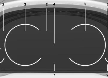
Warning area in front of the vehicle
The warning area in front of the vehicle is divided into two areas. ▷ Central area 1 directly in front of the vehicle. ▷ Expanded area 2 to the right and left. The entire area moves along with the vehicle in the direction of the steering angle and changes with the vehicle speed. As the vehicle speed in‐ creases, the area becomes longer and wider, for example.
Prewarning
The yellow symbol is displayed when a person is detected in the central area,
Online Edition for Part no. 01 40 2 903 008 - 07 12 490
111
Controls
Safety
arrow 1, immediately in front of the vehicle.
The yellow symbol is displayed when a person detected in the extended area, arrow 2, is moving from the right or left
to the central area.
Acute warning
The red symbol is displayed and a signal sounds. You are requested to intervene immediately by braking or making an
evasive maneuver. Display in the Head-up Display
The warning is displayed simultane‐ ously in the Head-Up Display and on the Control Display. The displayed symbol can vary with the people detected. For people located in the central area, the distance to the person is indicated by the size of the symbol. System limits Basic limits System operation is limited in situations such as the following: ▷ On steep hills, in steep depressions or in
tight curves.
▷ When the camera is dirty or the protective
glass is damaged.
▷ In heavy fog, rain or snowfall. ▷ At very high external temperatures. Limits of pedestrian detection Animals are not detected by the pedestrian de‐ tection function, even if they are clearly visible in the image. Limited pedestrian detection: ▷ People who are fully or partially covered, es‐
pecially when their heads are covered.
▷ People who are not in an upright position,
e.g., lying down.
▷ Cyclists on unconventional bicycles (e.g.,
recumbent bicycles).
▷ After physical damage to the system, e.g.,
after an accident.
No display on the rear screen The image from Night Vision with people detec‐ tion cannot be displayed on the rear screen. Activation/deactivation
Press the button.
Display Night Vision with pedestrian detection is not available on the rear screen. Adjustments via the iDrive With Night Vision switched on: 1. Activate Night Vision with pedestrian detec‐
tion.
2. Press the controller. 3. Open the desired menu item.
▷ ▷ ▷
"Brightness" "Contrast" "Pedestrian detection"
The settings are stored for the remote control currently in use.
112
Online Edition for Part no. 01 40 2 903 008 - 07 12 490
Camera
Safety
Controls
In the event of a warning, do not jerk the steering wheel, as you may lose control of the vehicle.◀
At a glance Button in the vehicle
Rain, dirt, snow, or ice can impair camera oper‐ ation. The camera is automatically heated when the external temperatures are low. The camera is automatically cleaned together with the headlamps. Clean the lens, refer to page 226.
Lane departure warning The concept Starting at a specific speed, this system alerts you when the vehicle on streets with lane mark‐ ings is about to leave the lane. Depending on the country-specific version of the vehicle, the speed is between 35 mph/55 km/h and 45 mph/70 km/h. When switching on the system below this speed, a message appears in the in‐ strument cluster. The steering wheel begins vibrating gently in the event of warnings. The time of the warning may vary depending on the current driving situation. The system does not provide a warning if the turn signal is set before leaving the lane. Notes
Personal responsibility The system cannot serve as a substitute for the driver's personal judgment of the course of the road and the traffic situation.
Lane departure warning
Camera
The camera is located near the base of the mir‐ ror. Keep the windshield in the area behind the in‐ terior rear view mirror clean and clear.
Switching on/off
Press the button
▷ On: the LED lights up. ▷ Off: the LED goes out. The state is stored for the remote control cur‐ rently in use.
Online Edition for Part no. 01 40 2 903 008 - 07 12 490
113
Controls
Safety
Display in the instrument cluster ▷ Lines: system is activated. ▷ Arrows: at least one lane marking was detected and warnings can be issued.
Display in the instrument display
▷ Symbol red: system is activated. ▷ Symbol green: at least one lane
marking was detected and warnings can be issued.
Issued warning If you leave the lane and if a lane marking has been detected, the steering wheel begins vi‐ brating. If the turn signal is set before changing the lane, a warning is not issued. End of warning The warning ends: ▷ Automatically after approx. 3 seconds. ▷ When returning to your own lane. ▷ When braking hard. ▷ When using the turn signal. System limits The system may not be fully functional in the following situations: ▷ In heavy fog, rain or snowfall. ▷ In the event of worn, poorly visible, merging, diverging, or multiple lane markings such as in construction areas.
▷ When lane markings are covered in snow,
ice, dirt or water.
▷ In tight curves or on narrow lanes. ▷ When the lane markings are covered by ob‐
jects.
▷ When driving very close to the vehicle in
front of you.
▷ When driving toward bright lights. ▷ When the windshield behind the interior
rearview mirror is fogged over, dirty or cov‐ ered with stickers, etc.
▷ During calibration of the camera immedi‐
ately after vehicle shipment.
Active Blind Spot Detection The concept
Two radar sensors below the rear bumper mon‐ itor the area behind and next to the vehicle at speeds above approx. 30 mph/50 km/h. The system indicates whether there are vehicles in the blind spot, arrow 1, or approaching from behind on the adjacent lane, arrow 2. The lamp in the exterior mirror housing lights up dimly. Before you change lanes after setting the turn signal, the system issues a warning in the situa‐ tions described above. The lamp in the housing of the exterior mirror flashes and the steering wheel vibrates. Notes
Personal responsibility The system does not serve as a substitute for the driver's personal judgment of the traffic situation. Be aware of the traffic situation and the vehicle's surroundings at all times, otherwise an accident is still possible despite all warnings.◀
114
Online Edition for Part no. 01 40 2 903 008 - 07 12 490
At a glance Radar sensors
Safety
Controls
Display
The radar sensors are located under the rear bumper.
Switching on/off
Press the button.
▷ On: the LED lights up. ▷ Off: the LED goes out. The system can issue warnings at speeds above approx. 30 mph/50 km/h. The state is stored for the remote control cur‐ rently in use.
Information stage The dimmed lamp in the mirror housing indi‐ cates when there are vehicles in the blind spot or approaching from behind. Warning If the turn signal is set while a vehicle is in the critical zone, the steering wheel vibrates briefly and the lamp in the mirror housing flashes brightly. The warning stops when the turn signal is switched off, or the other vehicle leaves the crit‐ ical zone. System limits The system may not be fully functional in the following situations: ▷ When a vehicle is approaching at a speed
much faster than your own. ▷ In heavy fog, rain or snowfall. ▷ In tight curves or on narrow lanes. ▷ If the bumper is dirty or iced up, or covered
with stickers.
For US owners only The transmitter and receiver units comply with part 15 of the FCC/Federal Communication Commission regulations. Operation is governed by the following: FCC ID: ▷ NBG009014A. Compliance statement:
Online Edition for Part no. 01 40 2 903 008 - 07 12 490
115
Controls
Safety
This device complies with part 15 of the FCC Rules. Operation is subject to the following two conditions: ▷ This device may not cause harmful interfer‐
ence, and
▷ this device must accept any interference re‐
ceived, including interference that may cause undesired operation.
Any unauthorized modifications or changes to these devices could void the user's authority to operate this equipment.
Brake force display The concept
▷ During normal brake application, the outer
brake lamps light up.
▷ During heavy brake application, the inner
brake lamps light up in addition.
Active Protection The concept The Active Protection safety package consists of systems that are independent of each other: ▷ PreCrash ▷ PostCrash
PreCrash The concept With this system critical driving situations that might result in an accident can be detected above a speed of approx. 19 mph/30 km/h. In in these situations, preventative protection meas‐ ures are automatically undertaken to minimize the risk in the event of an accident as much as possible. Critical driving situations may include: ▷ Full application of the brakes. ▷ Severe understeering. ▷ Severe oversteering. If the vehicle includes the collision warning or collision warning with braking feature, impend‐ ing collisions with vehicles driving ahead or stopped in front of you can also be detected within the system's range.
Personal responsibility The system cannot serve as a substitute for the driver's personal judgment of the traffic situation. The system may not always detect critical situations reliably and in a timely manner. Adapt speed to traffic situation and drive alertly; otherwise, a risk to safety may result.◀
Function After the safety belt is buckled, the front belts are automatically pretensioned once after the vehicle is driven is away. In critical driving situations, the following indi‐ vidual functions become active as needed: ▷ The front belts are automatically preten‐
sioned.
▷ Automatic closing of the windows. ▷ Automatic closing of the glass sunroof. ▷ Automatic Positioning of the backrest for
the front passenger seat.
After a critical driving situation without an acci‐ dent, the front belts are loosened again. All other systems can be restored to the desired setting.
116
Online Edition for Part no. 01 40 2 903 008 - 07 12 490
Safety
Controls
If the belt tension does not loosen automatically, stop the vehicle and unbuckle the belt using the red button in the buckle. Fasten the belt before continuing on your trip. PostCrash In the event of an accident, the system can bring the car to a halt automatically without interven‐ tion by the driver in certain situations. This can reduce the risk of a further collision. Depressing the brake pedal can cause the vehi‐ cle to brake harder. This interrupts automatic braking. Depressing the accelerator pedal also interrupts automatic braking. After coming to a halt, the brake is released au‐ tomatically. Secure the vehicle against rolling.
Online Edition for Part no. 01 40 2 903 008 - 07 12 490
117
Controls
Driving stability control systems
Driving stability control systems Vehicle equipment All standard, country-specific and optional equipment that is offered in the model series is described in this chapter. Therefore, equipment is also described that is not available in a vehicle, e. g., because of the selected optional equip‐ ment or country variant. This also applies for safety-related functions and systems.
Drive-off assistant This system supports driving away on gradients. The parking brake is not required. 1. Hold the vehicle in place with the foot brake. 2. Release the foot brake and drive away with‐
out delay.
Antilock Brake System ABS ABS prevents locking of the wheels during brak‐ ing. The vehicle remains steerable even during full brake applications, thus increasing active safety. ABS is operational every time you start the en‐ gine.
Brake assistant When you apply the brakes rapidly, this system automatically produces the maximum braking force boost. It thus helps to achieve the shortest possible braking distance during full braking. This system utilizes all of the benefits provided by ABS. Do not reduce the pressure on the brake pedal for the duration of the full braking.
Adaptive brake assistant In combination with the Active Cruise Control, this system ensures that the brakes respond even more rapidly when braking in critical situa‐ tions. Refer also to Collision warning, refer to page 106.
After the foot brake is released, the vehicle is held in place for approx. 2 seconds. Depending on the vehicle load or when a trailer is being used, the vehicle may roll back slightly.
Driving off without delay After releasing the foot brake, start driving without delay, since the drive-off assistant will not hold the vehicle in place for more than ap‐ prox. 2 seconds and the vehicle will begin rolling back.◀
DSC Dynamic Stability Control The concept DSC prevents traction loss in the driving wheels when driving away and accelerating. DSC also recognizes unstable vehicle condi‐ tions, such as fishtailing or nose-diving. Subject to physical limits, DSC helps to keep the vehicle on a steady course by reducing engine speed and by applying brakes at individual wheels. Adjust your driving style to the situation An appropriate driving style is always the
responsibility of the driver. The laws of physics cannot be repealed, even with DSC. Therefore, do not reduce the additional safety margin by driving in a risky manner.◀
118
Online Edition for Part no. 01 40 2 903 008 - 07 12 490
Driving stability control systems
Controls
Indicator/warning lamps
The indicator lamp flashes: DSC con‐ trols the drive forces and brake forces. The indicator lamp lights up: DSC has
failed.
Deactivating DSC: DSC OFF When DSC is deactivated, driving stability is re‐ duced during acceleration and when driving in bends. Stabilizing interventions by the Integral Active Steering system are only performed by the rear axle steering. To increase vehicle stability, activate DSC again as soon as possible. Deactivating DSC
Press and hold the button, but not lon‐ ger than approx. 10 seconds, until the indicator lamp for DSC OFF lights up in the in‐ strument cluster and DSC OFF is displayed. The DSC system is switched off.
Activating DSC
Press the button. DSC OFF and the DSC OFF indicator
lamp go out.
Indicator/warning lamps When DSC is deactivated, DSC OFF is dis‐ played in the instrument cluster.
The indicator lamp lights up: DSC is de‐ activated.
DTC Dynamic Traction Control The concept The DTC system is a version of the DSC in which forward momentum is optimized. The system ensures maximum forward momen‐ tum on special road conditions, e.g., unplowed snowy roads, but driving stability is limited. It is therefore necessary to drive with appropri‐ ate caution. You may find it useful to briefly activate DTC un‐ der the following special circumstances: ▷ When driving in slush or on uncleared,
snow-covered roads.
▷ When rocking the vehicle or driving off in
deep snow or on loose surfaces. ▷ When driving with snow chains. Deactivating/activating DTC Dynamic Traction Control Activating the Dynamic Traction Control DTC provides maximum traction on loose ground. Driving stability is limited during acceleration and when driving in bends. Activating DTC
Press the button. TRACTION is displayed in the instru‐
ment cluster and the indicator lamp for DSC OFF lights up.
Deactivating DTC
Press the button again. TRACTION and the DSC OFF indicator
lamp go out.
Indicator/warning lamps When DTC is activated, TRACTION is displayed in the tachometer.
Online Edition for Part no. 01 40 2 903 008 - 07 12 490
119
Controls
Driving stability control systems
The indicator lamp lights up: DTC Dy‐ namic Traction Control is activated.
xDrive xDrive is the all-wheel-drive system of your ve‐ hicle. Concerted action by the xDrive and DSC further optimize traction and driving dynamics. The xDrive all-wheel-drive system variably dis‐ tributes the drive forces to the front and rear axles as demanded by the driving situation and road surface.
HDC Hill Descent Control The concept HDC is a downhill driving assistant that auto‐ matically controls vehicle speed on steep down‐ hill gradients. Without applying the brakes, the vehicle moves at slightly more than walking speed. Hill Descent Control can be activated at speeds below approx. 22 mph/35 km/h. When driving downhill, the vehicle reduces its speed to ap‐ prox. walking speed and then keeps its speed constant. As long as there is active braking, the system is on standby. The system does not brake the ve‐ hicle during this time. Use HDC in low gears or in transmission position D or R only. Increasing or decreasing vehicle speed Specify desired speed in the range from approx. 4 mph/6 km/h to approx. 15 mph/25 km/h using the rocker switch of the cruise control on the steering wheel. Vehicle speed can be changed by lightly accelerating.
▷ Press up the rocker switch to the point of resistance: the speed increases gradually. ▷ Press up the rocker switch past the point of
resistance: the speed increases while the rocker switch is pressed.
▷ Press down the rocker switch to the point of resistance: the speed decreases gradually. ▷ Press down the rocker switch past the point
of resistance: when driving forward, the speed decreases to approx. 6 mph/10 km/h; when reversing, the speed decreases to ap‐ prox. 4 mph/6 km/h.
Activating HDC
Press the button; the LED above the but‐ ton lights up.
Deactivating HDC
Press the button again and the LED goes out. HDC is automatically deactivated
above approx. 37 mph/60 km/h.
120
Online Edition for Part no. 01 40 2 903 008 - 07 12 490
Driving stability control systems
Controls
Display in the instrument cluster
The selected speed is displayed in the speedometer. ▷ Green: the system is actively
braking the vehicle.
▷ Orange: the system is on
standby.
Malfunction A message is displayed in the instrument clus‐ ter. HDC is not available, e.g., due to elevated brake temperatures.
Adaptive Drive The concept Adaptive Drive includes the following systems: ▷ Dynamic Drive, refer to page 121
▷ Dynamic Damping Control, refer topage 121
The system increases driving stability and driv‐ ing comfort.
Dynamic Drive The concept Dynamic Drive reduces the lateral inclination of the vehicle that occurs during rapid driving in curves or during quick evasive maneuvers. Driving stability and driving comfort are in‐ creased under all driving conditions. The system utilizes active stabilizer bars on the front and rear axles that react immediately to all driving situa‐ tions. Programs The system offers two different programs. The programs can be selected via the Driving Experience Switch, refer to page 122.
SPORT Sporty tuning for greater driving agility. COMFORT Comfort-oriented tuning for optimal comfort.
Dynamic Damping Control The concept This system reduces undesirable vehicle mo‐ tion when using a dynamic driving style or trav‐ eling on uneven road surfaces. The system enhances driving dynamics and comfort as required for the road surface and driving style. Programs The system offers three different programs. The programs can be selected via the Driving Experience Switch, refer to page 122. SPORT Consistently sporty control of the shock absorb‐ ers for greater driving agility. COMFORT / ECO PRO Balanced tuning between the COMFORT+ and SPORT or SPORT+ programs. COMFORT+ Comfort-oriented tuning of the shock absorbers for optimal traveling comfort.
Integral Active Steering The concept Integral Active Steering is a combination of Ac‐ tive Steering and rear axle steering. Active Steering varies the steering angle of the wheels in relation to the steering wheel move‐ ment as a function of the speed.
Online Edition for Part no. 01 40 2 903 008 - 07 12 490
121
Controls
Driving stability control systems
At speeds up to approx. 37 mph/60 km/h, e.g., in curves, the steering angle is increased, i.e., steering becomes more direct. The rear axle steering acts to increase maneu‐ verability by turning the rear wheels slightly in a direction opposite to the front wheels. At higher speeds, the steering angle is increas‐ ingly reduced. The rear wheels are turned to the same angle as the front wheels. In critical situations, Integral Active Steering can specifically steer the front and rear wheels to stabilize the vehicle before the driver intervenes, e.g., when braking where road conditions differ on the left and right sides of the vehicle. Initializing In rare cases, it may become necessary to initi‐ alize the Integral Active Steering.
The warning lamp lights up. A Check Control message is displayed.
1. With the engine running, turn the steering wheel all the way to the left and right several times in a uniform manner until the warning lamp disappears.
2. Have the system checked if the warning
lamp does not go out after moving the steer‐ ing wheel approx. 6 times or if the steering wheel is at an angle. Using snow chains Ensure that the rear axle steering is deactivated when using snow chains, refer to page 199. Programs The system offers two different programs. The programs can be selected via the Driving Experience Switch, refer to page 122. SPORT Consistently sporty tuning of the Integral Active Steering for greater driving agility.
COMFORT Balanced tuning of the Integral Active Steering for optimal traveling comfort. Malfunction In the event of a malfunction, the steering wheel must be turned further, while the vehicle re‐ sponds more sensitively to steering wheel movements in the higher speed range. The stability-enhancing intervention may be de‐ activated. Proceed cautiously and drive defensively. Have the system checked.
Driving Experience Switch The concept The Driving Experience Switch can be used to adjust the driving dynamics of the vehicle. For this purpose various programs are available for selection that are activated via the two buttons of the Driving Experience Switch and the DSC OFF-button. Operating the programs
Press the button
Program DSC OFF TRACTION SPORT+ SPORT COMFORT COMFORT+ ECO PRO
Automatic program change The system automatically switches to COM‐ FORT in the following situations: ▷ Failure of Integral Active Steering. ▷ Failure of Dynamic Damping Control.
122
Online Edition for Part no. 01 40 2 903 008 - 07 12 490
Driving stability control systems
Controls
▷ The vehicle has a flat tire. DSC OFF When DSC OFF, refer to page 119, is active, driving stability is limited during acceleration and when driving in bends. TRACTION When TRACTION is active, the vehicle has max‐ imum traction on loose road surfaces. DTC Dy‐ namic Traction Control, refer to page 119, is ac‐ tivated. Driving stability is limited during acceleration and when driving in bends. SPORT+ Sporty driving with optimized chassis and sus‐ pension with limited driving stabilization. Dynamic Traction Control is switched on. The driver handles several of the stabilization tasks. Activating SPORT+
Press the button repeatedly until SPORT+ appears in the tachometer and the DSC indicator lamp lights up in the in‐ strument cluster.
Indicator/warning lamps SPORT+ is displayed in the instrument cluster. The DSC OFF indicator lamp lights up.
SPORT Consistently sporty tuning of the suspension for greater driving agility with maximum driving sta‐ bilization. The program can be configured to individual specifications. The configuration is stored for the remote con‐ trol currently in use.
Activating SPORT
Press the button repeatedly until SPORT appears in the tachometer.
Configuring SPORT When the display is activated on the Control Display, refer to page 124, the SPORTdriving mode can be set. After the SPORT driving mode is activated, se‐ lect "Configure SPORT" on the displayed panel and configure the program. SPORT can also be configured before it is acti‐ vated: 1. "Settings" 2. "SPORT mode" or: "Driving mode" 3. Configure driving mode. This configuration is retrieved when the SPORT driving mode is activated. COMFORT For a balanced tuning with maximum driving sta‐ bilization. Activating COMFORT
Press the button repeatedly until the program display in the tachometer
goes out. In certain situations, the system automatically changes to the NORMAL program, automatic program change, refer to page 122. COMFORT+ Comfort-oriented tuning of the shock absorbers for optimal traveling comfort with maximum driving stabilization. Activating COMFORT+
Press the button repeatedly until COM‐ FORT+ appears in the tachometer.
Online Edition for Part no. 01 40 2 903 008 - 07 12 490
123
Controls
Driving stability control systems
ECO PRO ECO PRO, refer to page 177, provides consis‐ tent tuning to minimize fuel consumption for maximum range with maximum driving stabili‐ zation. Comfort functions and the engine controller are adjusted. The program can be configured to individual specifications. Activating ECO PRO
Press button repeatedly until ECO PRO is displayed in the instrument cluster.
Configuring ECO PRO 1. Activate ECO PRO. 2. "Configure ECO PRO"
Program selection
Pressing the button displays a list of the selectable programs.
Display on the Control Display Program changes can be displayed briefly on the Control Display. To do so, make the following settings: 1. "Settings" 2. "Driving mode" 3. "Driving mode info"
Make the desired settings. Configure driving mode Settings can be made for the following driving modes in Driving mode: ▷ SPORT mode, refer to page 123. ▷ ECO PRO mode, refer to page 178. Displays in the instrument cluster Selected program
The selected program is dis‐ played in the tachometer.
124
Online Edition for Part no. 01 40 2 903 008 - 07 12 490
Driving comfort
Controls
General information When ECO PRO is activated, cruise control is also set to a driving style that saves on fuel con‐ sumption. Notes
Personal responsibility The system does not relieve the driver of the responsibility to adapt his or her speed, dis‐ tance and driving style to the traffic conditions. You should drive attentively and intervene ac‐ tively when necessary, e.g. by braking or making an evasive maneuver, otherwise, there is danger of an accident.◀
At a glance Buttons on the steering wheel
1 System on/off, interrupt 2 Resume speed 3 Store speed 4 Reduce distance 5 Store, maintain/change speed 6 Increase distance
Driving comfort Vehicle equipment All standard, country-specific and optional equipment that is offered in the model series is described in this chapter. Therefore, equipment is also described that is not available in a vehicle, e. g., because of the selected optional equip‐ ment or country variant. This also applies for safety-related functions and systems.
Active Cruise Control with Stop & Go function, ACC The concept This system can be used to select a desired speed that the vehicle will maintain automati‐ cally on clear roads. To the extent possible, the system automatically adjusts the speed to a slower vehicle ahead of you. The distance that the vehicle maintains to the vehicle ahead of you can be varied. For safety reasons, it depends on the speed. To maintain a certain distance, the system au‐ tomatically decelerates, applies the brakes lightly, or accelerates again if the vehicle ahead begins moving faster. If the vehicle ahead of you brakes to a halt, the system is able to detect this within the given system limits. If the vehicle ahead of your drives away again from a halt, your vehicle is able to accelerate if operated accordingly. Even if some time passes before the vehicle drives away again, the BMW can still be accel‐ erated automatically and simply. As soon as the road is clear, it accelerates to the desired speed. The speed is also maintained on downhill gra‐ dients, but may not be maintained on uphill slopes if engine power is insufficient.
Online Edition for Part no. 01 40 2 903 008 - 07 12 490
125
Controls
Driving comfort
Radar sensor
A dirty or covered sensor may hinder the detec‐ tion of vehicles. ▷ If necessary, clean the radar sensor. Re‐
move layers of snow and ice carefully.
▷ Do not cover the view field of the radar sen‐
sor.
Switching on/off and interrupting cruise control Switching on
Press the button on the steering wheel.
The indicator lamps in the instrument cluster light up and the mark in the speedometer is set to the current speed. Cruise control can be used. Switching off
Deactivated or interrupted system If the system is deactivated or interrupted, actively intervene by braking and, if necessary, with evasive maneuvers; otherwise, there is the danger of an accident occurring.◀ If switching off the system while stationary, press on the brake pedal at the same time.
Press the button.
▷ If active: press twice. ▷ If interrupted: press once.
The displays go out. The stored desired speed and distance are deleted. Interrupting the system
When active, press the button.
If interrupting the system while stationary, press on the brake pedal at the same time. The system is automatically interrupted in the following situations: ▷ When the brakes are applied. ▷ When the clutch pedal is depressed. ▷ When transmission position D is disen‐
gaged.
▷ When DTC Dynamic Traction Control is ac‐
tivated or DSC is deactivated.
▷ When DSC is actively controlling stability. ▷ If the safety belt and the driver's door are opened when the vehicle is standing still.
▷ If the system has not detected objects for an extended period, e.g., on a road with very lit‐ tle traffic without road edge line markings.
▷ If the radar sensor is dirty. Maintaining/storing the speed
Press the button. Or:
Press the rocker switch while the system is in‐ terrupted. When the system is switched on, the current speed is maintained and stored as the desired speed.
126
Online Edition for Part no. 01 40 2 903 008 - 07 12 490
It is displayed in the speedometer and briefly displayed in the instrument cluster, Displays in the instrument cluster, refer to page 128. When cruise control is maintained or stored, DSC Dynamic Stability Control is switched on, if necessary. Changing, maintaining, and storing the speed The rocker switch can be pressed while the sys‐ tem is interrupted to maintain and store the cur‐ rent speed. DSC Dynamic Stability Control is switched on, if necessary.
Adapting the desired speed Adapt the desired speed to the road con‐ ditions and be ready to brake at all times; other‐ wise, there is the danger of an accident occur‐ ring.◀
Speed differences Large differences in speed relative to ve‐ hicles ahead of the vehicle cannot be compen‐ sated by the system for example in the following situations: ▷ When catching up rapidly with a truck. ▷ When another vehicle suddenly swerves
into the wrong lane.◀
Press the rocker switch up or down repeatedly until the desired speed is set. If active, the displayed speed is stored and the vehicle reaches the stored speed if the road is clear. ▷ Each time the rocker switch is pressed to the
point of resistance, the desired speed in‐
Driving comfort
Controls
creases or decreases by approx. 1 mph/1 km/h.
▷ Each time the rocker switch is pressed past
the point of resistance, the desired speed increases or decreases by a maximum of 5 mph/10 km/h. Max. adjustable speed: 110 mph/180 km/h.
Hold the rocker switch in position to repeat the action.
Distance
Selecting a distance Adjust the distance according to the traffic and weather conditions; otherwise, there is the danger of an accident occurring. Maintain the prescribed safety distance.◀
Reduce distance
Press the button repeatedly until the desired distance is set.
The selected distance, refer to page 128, is dis‐ played in the instrument cluster. Increase distance
Press the button repeatedly until the desired distance is set.
The selected distance, refer to page 128, is dis‐ played in the instrument cluster. Calling up the desired speed and distance While driving
Press the button with the system switched on.
In the following cases, the stored speed value is deleted and cannot be called up again: ▷ When the system is switched off. ▷ When the ignition is switched off.
Online Edition for Part no. 01 40 2 903 008 - 07 12 490
127
Controls
Driving comfort
While standing
Before leaving the vehicle, secure it against rolling.
Before leaving the vehicle with the engine run‐ ning, engage position P of the automatic trans‐ mission and apply the parking brake. Otherwise, the vehicle may begin to roll.◀ The system brought the vehicle to a complete standstill. ▷ Green mark in the speedometer during a
brief idle phase: The vehicle ahead of you drives away while the mark is green: your vehicle accelerates without anything having to be done.
▷ Switch to orange of the mark in the speed‐
ometer after approx. 2 sec.: The vehicle ahead of you drives away, while the mark is orange: in order to accelerate, briefly press the gas pedal or press the RES button or SET button.
Rolling bars in the distance indicator mean that the vehicle ahead of you has driven off. You actively braked your vehicle to a halt by pressing on the brake pedal and it is standing behind another vehicle:
1.
Press the button to call up a stored
desired speed.
2. Release the brake pedal. 3. Press on the accelerator briefly, or press the RES button or the rocker switch when the vehicle ahead of you drives away.
Displays in the instrument cluster Desired speed
▷ The marking lights up green:
the system is active.
▷ The marking lights up or‐ ange: the system has been interrupted.
▷ The marking does not light up: the system is
switched off.
With instrument display: the symbol is displayed in the speedometer similarly to the mark for the desired speed.
Brief status display
Selected desired speed.
If --- appears briefly on the display for Check Control messages, it is possible that the system requirements for operation are currently not met. Distance to vehicle ahead of you The selected distance to the vehicle driving ahead of you is shown. Distance display
Distance 1
Distance 2
Distance 3
Distance 4
This value is set after the system is switched on. The system has been interrupted or distance control is deactivated be‐ cause the accelerator is being pressed; a vehicle was not detected. Distance control is deactivated be‐ cause the accelerator is being pressed; a vehicle was detected.Rolling bars: the detected vehicle has driven away.
128
Online Edition for Part no. 01 40 2 903 008 - 07 12 490
Indicator/warning lamps Personal responsibility The indicator and warning lamps do not relieve the driver of the responsibility to adapt his or her desired driving speed and style to the traffic conditions.◀
The vehicle symbol lights up orange: A vehicle has been detected ahead of you.
The vehicle symbol flashes orange: The conditions are not adequate for op‐ erating the system.
The system was deactivated but applies the brakes until you actively assume control by pressing on the brake pedal or accelerator.
The vehicle symbol flashes red and an acoustic signal sounds: You are requested to intervene by brak‐
ing or making an evasive maneuver.
Displays in the Head-up Display The information from Active Cruise Control can also be displayed in the Head-up Display. Adjusting the Head-up Display, refer to page 145. System limits Speed range Best results are achieved when using the sys‐ tem on well-developed roads and highways. The desired speed can be selected between 20 mph/30 km/h to 110 mph/180 km/h. The system can also be activated when station‐ ary. Comply with the legal speed limit in every situa‐ tion when using the system.
Driving comfort
Controls
Detection range
The detection capacity of the system and the automatic braking capacity are limited. Two-wheeled vehicles driving ahead of you for instance might not be detected.
Limited detection capacity Because of the limits to the detection ca‐ pacity, you should be alert at all times so that you can intervene actively, if necessary; otherwise, there is the danger of an accident occurring.◀
Deceleration The system does not decelerate when a sta‐ tionary obstacle is located in the same lane, e.g., a vehicle at a red traffic light or at the end of traffic congestion. The system also does not respond to: ▷ Pedestrians or similar slow-moving road
users.
▷ Red traffic lights. ▷ Stationary objects. ▷ Cross traffic. ▷ Oncoming traffic.
No warnings A warning may not be issued when ap‐
proaching a stationary or very slow-moving ob‐ stacle. You must react yourself; otherwise, there is the danger of an accident occurring.◀
Online Edition for Part no. 01 40 2 903 008 - 07 12 490
129
Controls
Driving comfort
Swerving vehicles
Cornering
If the desired speed is too high for a curve, the speed is reduced slightly in the curve, although curves cannot be anticipated in advance. There‐ fore, drive into a curve at an appropriate speed. In tight curves, situations may result due to the restricted detection range of the system in which a vehicle driving ahead of you may not be detected at all, or not until after a considerable delay.
A vehicle driving in front of you is not detected until it is completely within the same lane as your vehicle.
Swerving vehicles If a vehicle driving ahead of you suddenly swerves into your lane, the system may not be able to automatically restore the selected dis‐ tance. This also applies to major speed differ‐ ences to vehicles driving ahead of you, e.g., when rapidly approaching a truck. When a vehi‐ cle driving ahead of you is reliably detected, the system requests that the driver intervene by braking and carrying out evasive maneuvers, if necessary. You must react yourself; otherwise, there is the danger of an accident occurring.◀
Unexpected lane change
When approaching a curve, the system may re‐ act briefly to the vehicles in the next lane due to the bend of the curve. Any deceleration of the vehicle by the system can be compensated for by briefly accelerating. After the accelerator pedal is released, the system becomes active again and independently controls the speed.
If a vehicle ahead of you unexpectedly moves into another lane from behind a stopped vehicle, you yourself must react, as the system does not react to stopped vehicles.
Driving away In some situations, the vehicle cannot drive away automatically, e.g., on steep inclines or be‐ hind bumps in the road.
130
Online Edition for Part no. 01 40 2 903 008 - 07 12 490
Radar sensor For US owners only The transmitter and receiver units comply with part 15 of the FCC/Federal Communication Commission regulations. Operation is governed by the following: FCC ID: ▷ OAYARS3-A Compliance statement: This device complies with part 15 of the FCC Rules. Operation is subject to the following two conditions: ▷ This device may not cause harmful interfer‐
ence, and
▷ this device must accept any interference re‐
ceived, including interference that may cause undesired operation.
Any unauthorized modifications or changes to these devices could void the user's authority to operate this equipment. Malfunction The system cannot be activated if the radar sen‐ sor is not aligned correctly. This may be caused by damage incurred during parking, for example. A Check Control message is displayed if the system fails.
Cruise control The concept The system is functional at speeds beginning at approx. 20 mph/30 km/h. It maintains the speed that was set using the control elements on the steering wheel. The system brakes on downhill gradients if en‐ gine braking action is insufficient.
Driving comfort
Controls
Unfavorable conditions Do not use the system if unfavorable con‐ ditions make it impossible to drive at a constant speed, for instance: ▷ On curvy roads. ▷ In heavy traffic. ▷ On slippery roads, in fog, snow or rain, or on
a loose road surface.
Otherwise, you could lose control of the vehicle and cause an accident.◀
General information When ECO PRO is activated, cruise control is also set to a driving style that saves on fuel con‐ sumption. Controls At a glance
1 System on/off, interrupt 2 Resume speed 3 Store speed 4 Store, maintain/change speed
Switching on
Press the button on the steering wheel.
The marking in the speedometer is set to the current speed. Cruise control can be used.
Online Edition for Part no. 01 40 2 903 008 - 07 12 490
131
Controls
Driving comfort
Switching off
Deactivated or interrupted system If the system is deactivated or interrupted, actively intervene by braking and, if necessary, with evasive maneuvers; otherwise, there is the danger of an accident occurring.◀
Press the button.
▷ If active: press twice. ▷ If interrupted: press once. The displays go out. The stored desired speed is deleted. Interrupting the system
When active, press the button.
The system is automatically interrupted if: ▷ The brakes are applied. ▷ The clutch pedal is depressed for a few sec‐
onds or released while a gear is not en‐ gaged.
▷ The transmission position D is disengaged. ▷ DTC Dynamic Traction Control is activated
or DSC is deactivated.
▷ DSC is actively controlling stability. ▷ HDC is activated. Maintaining/storing the current speed
Press the rocker switch while the system is in‐ terrupted.
When the system is switched on, the current speed is maintained and stored as the desired speed. It is displayed in the speedometer and briefly displayed in the instrument cluster, Displays in the speedometer, refer to page 133. When cruise control is maintained or stored, DSC Dynamic Stability Control is switched on, if necessary. Changing/maintaining speed The rocker switch can be pressed while the sys‐ tem is interrupted in order to maintain and store the current speed.
Adapting the desired speed Adapt the desired speed to the road con‐ ditions and be ready to brake at all times; other‐ wise, there is the danger of an accident occur‐ ring.◀
Press the rocker switch up or down repeatedly until the desired speed is set. If active, the displayed speed is stored and the vehicle reaches the stored speed if the road is clear. ▷ Each time the rocker switch is pressed to the
point of resistance, the desired speed in‐ creases or decreases by approx. 1 mph/1 km/h.
▷ Each time the rocker switch is pressed past
the point of resistance, the desired speed increases or decreases by a maximum of 5 mph/10 km/h. Max. adjustable speed: 140 mph/230 km/h.
132
Online Edition for Part no. 01 40 2 903 008 - 07 12 490
Driving comfort
Controls
PDC Park Distance Control The concept PDC supports you when parking. Objects that you are approaching slowly in front of or behind your vehicle are indicated by: ▷ Signal tones. ▷ Visual display. General information Measurements are made by ultrasound sensors in the bumpers. The range is approx. 6 ft/2 m. An acoustic warning is first given: ▷ By the front sensors and the two rear corner
sensors at approx. 24 in/60 cm.
▷ By the rear middle sensors at approx.
5 ft/1.50 m.
Notes
Check the traffic situation as well PDC cannot serve as a substitute for the driver's personal judgment of the traffic situa‐ tion. Check the traffic situation around the vehi‐ cle with your own eyes. Otherwise, an accident could result from road users or objects located outside of the PDC detection range. Loud noises from outside and inside the vehicle may prevent you from hearing the PDC's signal tone.◀
Avoid driving quickly with PDC Avoid approaching an object quickly.
Avoid driving away quickly while PDC is not yet active. For technical reasons, the system may other‐ wise be too late in issuing a warning.◀
▷ Pressing the rocker switch to the resistance point and holding it there accelerates or de‐ celerates the vehicle without requiring pres‐ sure on the accelerator. After the rocker switch is released, the vehicle maintains its final speed. Pressing the switch beyond the resistance point causes the vehicle to ac‐ celerate more rapidly.
Resuming the desired speed
Press the button.
The stored speed is reached and maintained. Displays in the instrument cluster Indicator lamp
Depending on how the vehicle is equip‐ ped, the indicator lamp in the instrument cluster indicates whether the system is
switched on.
Desired speed
▷ The marking lights up green:
the system is active.
▷ The marking lights up or‐ ange: the system has been interrupted.
▷ The marking does not light up: the system is
switched off.
With instrument display: the symbol is displayed in the speedometer similarly to the mark for the desired speed.
Brief status display
Selected desired speed.
If --- appears briefly on the display for Check Control messages, it is possible that the system requirements for operation are currently not met.
Online Edition for Part no. 01 40 2 903 008 - 07 12 490
133
Controls
Driving comfort
At a glance Button in the vehicle
PDC Park Distance Control
Switching on/off Switching on automatically Select transmission position R with the engine running. Automatic deactivation during forward travel The system switches off when a certain driving distance or speed is exceeded. Switch the system back on if necessary. Switching on/off manually
Press the button.
▷ On: the LED lights up. ▷ Off: the LED goes out. In addition to the PDC Park Distance Control, the backup camera, refer to page 135, can be switched on. Switching on the backup camera via the iDrive With PDC activated:
"Rear view camera"
The backup camera image is displayed. The set‐ ting is stored for the remote control currently in use.
Display Signal tones When approaching an object, an intermittent tone is sounded that indicates the position of the object. For example, if an object is detected to the left rear of the vehicle, a signal tone sounds from the left rear speaker. The shorter the distance to the object becomes, the shorter the intervals. If the distance to a detected object is less than approx. 10 in/25 cm, a continuous tone is sounded. If objects are located both in front of and behind the vehicle, an alternating continuous signal is sounded. The intermittent tone is interrupted after approx. 3 seconds: ▷ If the vehicle stops in front of an object that is detected by only one of the corner sen‐ sors.
▷ If moving parallel to a wall. The signal tone is switched off: ▷ When the vehicle moves away from an ob‐
ject by more than approx. 4 in/10 cm.
▷ When transmission position P is engaged. Volume The volume of the PDC signal can be adjusted, refer to user's manual for Navigation, Entertain‐ ment and Communication. The setting is stored for the remote control cur‐ rently in use. Visual warning The approach of the vehicle to an object can be shown on the Control Display. Objects that are farther away are displayed on the Control Dis‐ play before a signal tone sounds. A display appears as soon as Park Distance Control (PDC) is activated.
134
Online Edition for Part no. 01 40 2 903 008 - 07 12 490
Driving comfort
Controls
Malfunction A Check Control message is displayed. The range of the sensors is shown as a shaded area on the Control Display. PDC has failed. Have the system checked. To ensure full operability: ▷ Keep the sensors clean and free of ice. ▷ When using high-pressure washers, do not spray the sensors for long periods and main‐ tain a distance of at least 12 in/30 cm.
Surround View The concept Surround View includes the following systems: ▷ Backup camera, refer to page 135. ▷ Side View, refer to page 140. ▷ Top View, refer to page 138. It assists the driver when parking, maneuvering and on blind driveways and intersections.
Backup camera The concept The backup camera provides assistance in park‐ ing and maneuvering backwards. The area be‐ hind the vehicle is shown on the Control Display. Notes
Check the traffic situation as well Check the traffic situation around the ve‐ hicle with your own eyes. Otherwise, an accident could result from road users or objects located outside the picture area of the backup camera.◀
The range of the sensors is represented in col‐ ors: red, green and yellow. If the backup camera image was selected last, it again appears on the display. To switch to PDC: "Rear view camera" Select the symbol 1.
on the Control Display.
2. Press the controller. The setting is stored for the remote control cur‐ rently in use. System limits Limits of ultrasonic measurement The detection of objects can reach the physical limits of ultrasonic measurement, e.g.: ▷ With tow bars and trailer hitches. ▷ With thin or wedge-shaped objects. ▷ With low objects. ▷ With objects with corners and sharp edges. Low objects already displayed, e.g., curbs, can move into the blind area of the sensors before or after a continuous tone sounds. High, protruding objects such as ledges may not be detected. False warnings PDC may issue a warning under the following conditions even though there is no obstacle within the detection range: ▷ In heavy rain. ▷ When sensors are very dirty or covered in
ice.
▷ When sensors are covered in snow. ▷ On rough road surfaces. ▷ In large buildings with right angles and
smooth walls, e.g., in underground garages.
▷ In heavy exhaust. ▷ Due to other ultrasound sources, e.g.,
sweeping machines, high pressure steam cleaners or neon lights.
Online Edition for Part no. 01 40 2 903 008 - 07 12 490
135
Switching on/off manually
Press the button.
▷ On: the LED lights up. ▷ Off: the LED goes out. The PDC is shown on the Control Display. Switch on the backup camera via the iDrive, refer to page 134. Switching on the backup camera via the iDrive With PDC activated:
"Rear view camera"
The backup camera image is displayed. The set‐ ting is stored for the remote control currently in use. Display on the Control Display Functional requirement ▷ The backup camera is switched on. ▷ The trunk lid is fully closed. Activating the assistance functions More than one assistance function can be active at the same time. ▷ Parking aid lines
"Parking aid lines"
Pathway and turning circle lines are dis‐ played.
▷ Obstacle marking
"Obstacle marking"
Spatially-shaped markings are displayed.
Controls
Driving comfort
At a glance Button in the vehicle
Backup camera
Camera
The camera lens is located in the handle of the trunk lid. The image quality may be impaired by dirt. Clean the lens, refer to page 226.
Switching on/off Switching on automatically Select transmission position R with the engine running. The backup camera image is displayed if the system was switched on via the iDrive. Automatic deactivation during forward travel The system switches off when a certain driving distance or speed is exceeded. Switch the system back on if necessary.
136
Online Edition for Part no. 01 40 2 903 008 - 07 12 490
Pathway lines
Obstacle marking
Driving comfort
Controls
▷ Can be shown in the backup camera image
when in transmission position R.
▷ Help you to estimate the space required when parking and maneuvering on level roads.
▷ Are dependent on the current steering angle and are continuously adjusted to the steer‐ ing wheel movements.
Turning circle lines
▷ Spatially-shaped markings can be shown in
the backup camera image.
Their colored steps match the markings of the PDC. This simplifies estimation of the distance to the object shown.
Parking using pathway and turning circle lines 1. Position the vehicle so that the turning circle lines lead to within the limits of the parking space.
▷ Can be shown in the backup camera image. ▷ Show the course of the smallest possible
turning circle on a level road.
▷ Only one turning circle line is displayed
when the steering wheel is turned.
2. Turn the steering wheel to the point where the pathway line covers the corresponding turning circle line.
Online Edition for Part no. 01 40 2 903 008 - 07 12 490
137
Controls
Driving comfort
Display settings Brightness With the backup camera switched on: 1. 2. Turn the controller until the desired setting
Select the symbol.
is reached and press the controller.
Contrast With the backup camera switched on: 1. 2. Turn the controller until the desired setting
Select the symbol.
is reached and press the controller.
System limits Detection of objects High, protruding objects such as ledges may not be detected by the backup camera.
Top View The concept Top View assists you in parking and maneuver‐ ing. The area around the doors and the road area around the vehicle are shown on the Control Display for this purpose. General information The image is captured by two cameras integrated in the exterior mirrors and by the backup camera. The range is at least 7 ft/2 m to the side and rear. In this way, obstacles up to the height of the ex‐ terior mirrors are detected early.
Notes
Check the traffic situation as well Check the traffic situation around the ve‐ hicle with your own eyes. Otherwise, an accident could result from road users or objects located outside the picture area of the cameras.◀
At a glance Button in the vehicle
Top View
Cameras
The lenses of the Top View cameras are located at the bottom of the exterior mirror housings. The image quality may be impaired by dirt. Clean the lens, refer to page 226.
Switching on/off Switching on automatically Select transmission position R with the engine running.
138
Online Edition for Part no. 01 40 2 903 008 - 07 12 490
The Top View and PDC images are displayed if the system is switched on via iDrive. Automatic deactivation during forward travel The system switches off when a certain driving distance or speed is exceeded. Switch the system back on if necessary. Switching on/off manually
Press the button.
▷ On: the LED lights up. ▷ Off: the LED goes out. Top View is displayed, switch on the backup camera via the iDrive, refer to page 139. Switching on the backup camera via the iDrive With Top View switched on:
"Rear view camera"
The backup camera image is displayed. The set‐ ting is stored for the remote control currently in use. Display Visual warning The approach of the vehicle to an object can be shown on the Control Display. When the distance to an object is small, a red bar is shown in front of the vehicle, as it is in the PDC display.
Driving comfort
Controls
The display appears as soon as Top View is ac‐ tivated. If the backup camera image was selected last, it again appears on the display when reverse gear is selected. To switch to Top View:
"Rear view camera" Select the symbol on
the Control Display. The setting is stored for the remote control cur‐ rently in use. Brightness With Top View switched on: 1. 2. Turn the controller until the desired setting
"Brightness"
is reached and press the controller.
Contrast With Top View switched on: 1. 2. Turn the controller until the desired setting
"Contrast"
is reached and press the controller. Displaying the turning circle and pathway lines ▷ The static, red turning circle line shows the
space needed to the side of the vehicle when the steering wheel is turned all the way.
▷ The variable, green pathway line assists you in assessing the amount of space actually needed to the side of the vehicle.
Online Edition for Part no. 01 40 2 903 008 - 07 12 490
139
Controls
Driving comfort
The pathway line is dependent on the cur‐ rent steering angle and is continuously ad‐ justed with the steering wheel movement.
At a glance Button in the vehicle
"Parking aid lines"
Turning circle and pathway lines are displayed. System limits Top View cannot be used in the following situa‐ tions: ▷ With a door open. ▷ With the trunk lid open. ▷ With an exterior mirror folded in. ▷ In poor light. A Check Control message is displayed in some of these situations.
Side View The concept Side View provides an early look at cross traffic at blind driveways and intersections. Road users concealed by obstacles to the left and right of the vehicle can only be detected relatively late from the driver's seat. To improve visibility, two cameras in the front of the vehicle record the traffic situation on each side. Notes The images from both cameras are shown si‐ multaneously on the Control Display.
Check the traffic situation as well Check the traffic situation around the ve‐ hicle on blind driveways and intersections with your own eyes. Otherwise, an accident could re‐ sult from road users or objects located outside the picture area of the Side View cameras.◀
Side View
Cameras
Two cameras integrated in the bumpers capture the image. The two camera lenses are located on the sides of the bumper. The image quality may be impaired by dirt. Clean the lens, refer to page 226.
Switching on/off Switching on/off manually
Press the button.
Automatic deactivation during forward travel The system switches off when a certain driving distance or speed is exceeded.
140
Online Edition for Part no. 01 40 2 903 008 - 07 12 490
Switch the system back on if necessary. Display The traffic area to the left and right is displayed on the Control Display.
Driving comfort
Controls
Parking assistant The concept
Guidelines at the bottom of the image show the position of the front of the vehicle.
Brightness With the Side View switched on: 1. 2. Turn the controller until the desired setting
"Brightness"
is reached and press the controller.
Contrast With the Side View switched on: 1. 2. Turn the controller until the desired setting
"Contrast"
is reached and press the controller.
System limits The cameras capture a maximum range of 330 ft/100 m.
This system assists the driver in parking parallel to the road. Ultrasound sensors measure parking spaces on both sides of the vehicle. The parking assistant calculates the best pos‐ sible parking line and takes control of steering during the parking procedure. A component of the parking assistant is the PDC Park Distance Control, refer to page 133. Notes
Personal responsibility The parking assistant does not relieve the driver of responsibility for the vehicle during the parking procedure. Watch the parking space and parking procedure closely and intervene if necessary; otherwise, there is the danger of an accident.◀ Changes to the parking space Changes to the parking space after it was measured are not taken into account by the sys‐ tem. Therefore, always be alert and ready to inter‐ vene; otherwise, there is the danger of an acci‐ dent occurring.◀
Transporting loads Loads that extend beyond the perimeter of the vehicle are not taken into account by the system during the parking procedure.
Online Edition for Part no. 01 40 2 903 008 - 07 12 490
141
Controls
Driving comfort
Therefore, always be alert and ready to inter‐ vene; otherwise, there is the danger of an acci‐ dent occurring.◀
At a glance Button in the vehicle
Curbs The parking assistant may steer the vehi‐
cle over or onto curbs. Therefore, always be alert and ready to inter‐ vene; otherwise, the wheels, tires, or the vehicle may become damaged.◀ An engine that has been switched off by the Auto Start Stop function is restarted automati‐ cally when the parking assistant is activated. Requirements For measuring parking spaces ▷ Maximum speed while driving forward ap‐
prox. 22 mph/35 km/h.
▷ Maximum distance to row of parked vehi‐
cles: 5 ft/1.5 m.
▷ When parking in parking spaces on the driv‐ er's side, the corresponding turn signal must be set.
Suitable parking space ▷ Gap between two objects with a minimum
length of approx. 5 ft/1.5 m.
▷ Minimum length of the gap: own vehicle's
length plus approx 4 ft/1.2 m.
▷ Minimum depth: approx. 5 ft/1.5 m. For parking procedure Closed doors.
Parking assistant
Ultrasound sensors
The ultrasounds sensors used to measure park‐ ing spaces are located in the side turn signals. To ensure full operability: ▷ Keep the sensors clean and free of ice. ▷ When using high-pressure washers, do not spray the sensors for long periods and main‐ tain a distance of at least 12 in/30 cm.
Switching on/off Switching on with the button
Press the button. The LED lights up.
The current status of the parking space search is indicated on the Control Display.
Parking assistant is activated automatically.
142
Online Edition for Part no. 01 40 2 903 008 - 07 12 490
Driving comfort
Controls
The parking procedure is active. Steering control has been seized.
Status of the parking space search
Switching on with reverse gear Shift into reverse. The current status of the parking space search is indicated on the Control Display. Activate: symbol in the Control Display. Switching off The system can be deactivated as follows: ▷
"Parking Assistant" Select the
Press the button.
▷ Switch off the ignition. Display on the Control Display Activating/deactivating the system
Symbol Meaning
Gray: the system is not available. White: the system is available but not activated. The system is activated.
Without Professional navigation