- Download PDF Manual
-
▷ The indicator lamp flashes briefly every
2 seconds: The system is armed.
▷ The indicator lamp flashes after locking:
42
Online Edition for Part no. 01 40 2 903 008 - 07 12 490
The doors, hood or trunk lid is not closed properly, but the rest of the vehicle is se‐ cured. After 10 seconds, the indicator lamp flashes continuously. Interior motion sensor and tilt alarm sensor are not active.
▷ The indicator lamp goes out after unlocking:
The vehicle has not been tampered with. ▷ The indicator lamp flashes after unlocking until the engine is started, but no longer than approx. 5 minutes: An alarm has been triggered.
Tilt alarm sensor The tilt of the vehicle is monitored. The alarm system responds in situations such as attempts to steal a wheel or when the car is towed. Interior motion sensor The windows and glass sunroof must be closed for the system to function properly. Avoiding unintentional alarms The tilt alarm sensor and interior motion sensor can be switched off together, such as in the fol‐ lowing situations: ▷ In automatic car washes. ▷ In duplex garages. ▷ During transport on car-carrying trains, at
sea or on a trailer.
▷ When animals are to remain in the vehicle. Switching off the tilt alarm sensor and interior motion sensor
Press the remote control button again within 10 seconds as soon as the vehicle
is locked. The indicator lamp lights up for approx. 2 sec‐ onds and then continues to flash.
Opening and closing
Controls
The tilt alarm sensor and interior motion sensor are switched off until the vehicle is locked again.
Power windows General information
Take the remote control with you Take the remote control with you when
leaving the vehicle so that children, for example, cannot operate the power windows and injure themselves.◀
Opening
▷
▷
Press the switch to the resistance
point. The window opens while the switch is held.
Press the switch beyond the resist‐
ance point. The window opens automatically.
Pressing again stops the motion. Convenient opening, refer to page 34, via the remote control. Closing
Keep the closing path clear Monitor the closing process and make
sure that the closing path of the window is clear; otherwise, injuries may result.◀
▷
Pull the switch to the resistance point.
Online Edition for Part no. 01 40 2 903 008 - 07 12 490
43
2. Pull the switch past the resistance point
again within approx. 4 seconds and hold it there. The window closes without pinch protec‐ tion.
Safety switch The safety switch in the driver's door can be used to prevent children, for example, from opening and closing the rear windows using the switches in the rear. Switching on and off Press the button. The LED lights up if the safety function
is switched on.
Safety switch for rear operation Press the safety switch when transporting children in the rear; otherwise, injury may result if the windows are closed without supervision.◀
Roller sunblinds General information If you are no longer able to move the roller sun‐ blind for the rear window after having activated it a number of times in a row, the system is blocked for a limited time to prevent overheat‐ ing. Let the system cool. The roller sunblind for the rear window cannot be moved at low interior temperatures.
Controls
Opening and closing
The window closes while the switch is held.
▷
Pull the switch beyond the resistance
point. The window closes automatically. Pressing the switch stops the motion. Convenient operation, refer to page 34, via the remote control. Convenient closing, refer to page 41, with Com‐ fort Access. Pinch protection system If the closing force exceeds a specific value as a window closes, the closing action is interrupted. The window reopens slightly.
Danger of pinching even with pinch pro‐ tection
Even with the pinch protection system, check that the window's closing path is clear; other‐ wise, the closing action may not stop in certain situations, e.g., if thin objects are present.◀
No window accessories Do not install any accessories in the range
of movement of the windows; otherwise, the pinch protection system will be impaired.◀
Closing without the pinch protection system
Keep the closing path clear Monitor the closing process and make
sure that the closing path of the window is clear; otherwise, injuries may result.◀ For example, if there is an external danger or if ice on the windows prevents a window from closing normally, proceed as follows: 1. Pull the switch past the resistance point and
hold it there. Pinch protection is limited and the window reopens slightly if the closing force exceeds a certain value.
44
Online Edition for Part no. 01 40 2 903 008 - 07 12 490
Driver's door controls
Opening and closing
Controls
Take the remote control with you Take the remote control with you when
leaving the vehicle so that children, for example, cannot operate the roof and injure themselves.◀
Roller blind for rear window
Press the button.
Roller sunblinds for the rear side windows Pull out the roller sunblind at the loop and hook it onto the bracket.
Do not open the window while the roller sunblind is raised.
Do not open the window while the roller sunblind is raised; otherwise, there is a risk of damage at high speeds that may result in personal injury.◀
Glass sunroof, powered General information The glass sunroof and the sliding visor can be operated together or separately, using the same switch. The glass sunroof is operational when the igni‐ tion is switched on.
Keep the closing path clear Monitor the closing process and make
sure that the closing path of the glass sunroof is clear; otherwise, injuries may result.◀
Tilting the glass sunroof
Push switch upward briefly. ▷ The closed roof is tilted and
the sliding visor opens slightly.
▷ The opened roof closes until it is in its tilted position. The sliding visor stays completely open.
Opening/closing the sliding visor
▷ Press the switch in the de‐ sired direction to the resist‐ ance point and hold it there. The sliding visor moves while the switch is being held. ▷ Press the switch in the desired direction
past the resistance point. The sliding visor moves automatically. Pressing the switch again stops the motion.
Opening/closing the glass sunroof When the sliding visor is open, proceed as de‐ scribed under Sliding visor.
Online Edition for Part no. 01 40 2 903 008 - 07 12 490
45
Closing from the raised position without pinch protection If there is an external danger, push the switch forward past the resistance point and hold it. The roof closes without pinch protection. Initializing after a power failure After a power failure during the opening or clos‐ ing process, the roof can only be operated to a limited extent. Initializing the system The system can be initialized when the vehicle is stationary and the engine is running. During the initialization, the roof closes without pinch protection.
Keep the closing path clear Monitor the closing process and make
sure that the closing path of the glass sunroof is clear; otherwise, injuries may result.◀
Press the switch up and hold it until the initialization is complete: ▷ Initialization begins within
15 seconds and is completed when the sunroof and sliding visor are completely closed. ▷ The roof closes without pinch protection.
Controls
Opening and closing
Opening/closing the glass sunroof and sliding visor together
Briefly press the switch twice in succession in the desired direc‐ tion past the resistance point. The glass sunroof and sliding vi‐ sor move together. Pressing the
switch again stops the motion. Convenient operation, refer to page 34, via the remote control. Convenient closing, refer to page 41, with Com‐ fort Access. Pinch protection system If the closing force when closing the glass sun‐ roof exceeds a certain value, the closing move‐ ment is stopped, beginning at approximately the middle of the opening in the roof, or from the tilted position during closing. The glass sunroof opens again slightly.
Danger of pinching even with pinch pro‐ tection
Despite the pinch protection system, check that the roof's closing path is clear; otherwise, the closing action may not be interrupted in certain extreme situations, such as when thin objects are present.◀
Closing from the open position without pinch protection For example, if there is an external danger, pro‐ ceed as follows: 1. Press the switch forward beyond the resist‐
ance point and hold. Pinch protection is limited and the roof re‐ opens slightly if the closing force exceeds a certain value.
2. Press the switch forward again beyond the
resistance point and hold until the roof closes without pinch protection.
46
Online Edition for Part no. 01 40 2 903 008 - 07 12 490
Adjusting
Controls
Semi-electrically adjustable seats At a glance
1 Thigh support 2 Tilt 3 Forward/backward 4 Lumbar support 5 Height 6 Backrest
Tilt
Pull the lever and move the seat to the desired tilt. After releasing the lever, apply your weight to the seat or lift it off to make sure the seat en‐ gages properly.
Adjusting Vehicle equipment All standard, country-specific and optional equipment that is offered in the model series is described in this chapter. Therefore, equipment is also described that is not available in a vehicle, e. g., because of the selected optional equip‐ ment or country variant. This also applies for safety-related functions and systems.
Sitting safely The ideal seating position can make a vital con‐ tribution to relaxed, fatigue-free driving. The seating position plays an important role in an accident in combination with: ▷ Safety belts, refer to page 51. ▷ Head restraints, refer to page 52. ▷ Airbags, refer to page 98.
Seats General information
Do not adjust the seat while driving Do not adjust the driver's seat while driv‐ ing, or the seat could respond with unexpected movement and the ensuing loss of vehicle con‐ trol could lead to an accident.◀
Do not incline the backrest too far to the rear
Also on the front passenger side, do not incline the backrest on the front passenger side too far to the rear during driving, or there is a risk of slipping under the safety belt in the event of an accident. This would eliminate the protection normally provided by the belt.◀
Online Edition for Part no. 01 40 2 903 008 - 07 12 490
47
Controls
Adjusting
Forward/backward
Electrically adjustable seats At a glance
Pull the lever and slide the seat in the desired direction. After releasing the lever, move the seat forward or back slightly to make sure it engages prop‐ erly.
Height
1 Lumbar support 2 Backrest width 3 Shoulder support 4 Backrest 5 Forward/back, height, tilt 6 Thigh support
Note The seat setting for the driver's seat is stored for the remote control currently in use. When the vehicle is unlocked via the remote control, the position is automatically retrieved if the Func‐ tion, refer to page 35, for this is activated. Adjustments in detail 1. Forward/back.
Move the button in the required direction.
Backrest
Move the button in the required direction.
48
Online Edition for Part no. 01 40 2 903 008 - 07 12 490
2. Height.
3. Seat tilt.
4. Backrest tilt.
5. Thigh support.
Adjusting
Controls
Lumbar support The curvature of the seat backrest can be ad‐ justed in such a way that it supports the lumbar region of the spine. The lower back and the spine are supported for upright posture.
▷ Press the front/rear section of
the switch. The curvature is increased/ decreased.
▷ Press the upper/lower sec‐
tion of the switch. The curvature is shifted up/ down.
Shoulder support
Also supports the back in the shoulder area: ▷ Results in a relaxed seating position. ▷ Reduces strain on the shoulder muscles.
Active seat Active adjustment of the seat cushion's con‐ tours reduces muscular tension and fatigue to help prevent lower back pain.
Online Edition for Part no. 01 40 2 903 008 - 07 12 490
49
Controls
Adjusting
Press the button. The LED lights up.
3. Select the required seat.
Front seat heating
Switching on
Press the button once for each temper‐ ature level.
The maximum temperature is reached when three LEDs are lit. If the drive is continued within approx. 15 mi‐ nutes, the seat heating is activated automati‐ cally with the temperature selected last. When ECO PRO, refer to page 177, is activated, the heater output is reduced.
Switching off
Press the button longer. The LEDs go out.
Temperature distribution The heating action in the seat cushion and back‐ rest can be distributed in different ways. 1. "Climate" 2. "Seat heating distribution"
4. Turn the controller to set the temperature
distribution.
Rear seat heating
Switching on
Press the button once for each temper‐ ature level.
The maximum temperature is reached when three LEDs are lit. If the drive is continued within approx. 15 mi‐ nutes, the seat heating is activated automati‐ cally with the temperature selected last. When ECO PRO, refer to page 177, is activated, the heater output is reduced.
Switching off
Press the button longer. The LEDs go out.
Active seat ventilation, front The seat cushion and backrest surfaces are cooled by means of integrated fans.
50
Online Edition for Part no. 01 40 2 903 008 - 07 12 490
Adjusting
Controls
Although airbags enhance safety by providing added protection, they are not a substitute for safety belts. ▷ The shoulder strap's anchorage point will be
correct for adult seat occupants of every build if the seat is correctly adjusted.
▷ The two outer safety belt buckles,
integrated into the rear seat, are for passen‐ gers sitting on the left and right.
▷ The center rear seat belt buckle is solely in‐
tended for the center passenger.
One person per safety belt Never allow more than one person to wear a single safety belt. Never allow infants or small children to ride on a passenger's lap.◀
Putting on the belt Lay the belt, without twisting, snugly
across the lap and shoulders, as close to the body as possible. Make sure that the belt lies low around the hips in the lap area and does not press on the abdomen. Otherwise, the belt can slip over the hips in the lap area in a frontal im‐ pact and injure the abdomen. The safety belt must not lie across the neck, rub on sharp edges, be routed over solid or breaka‐ ble objects, or be pinched.◀
Reduction of restraining effect Avoid wearing clothing that prevents the belt from fitting properly, and pull the shoulder belt periodically to readjust the tension across your lap; otherwise, the retention effect of the safety belt may be reduced.◀
The ventilation rapidly cools the seat, e. g., if the vehicle interior is overheated or for continuous cooling at high temperatures.
Switching on
Press the button once for each ventila‐ tion level.
The highest level is active when three LEDs are lit. If when the seat ventilation is turned on the Max‐ imum Cooling function is activated, the seat ventilation automatically switches to the highest level. When the Maximum Cooling function is switched off, the unit switches back to the pre‐ viously set level. After a short time, the system automatically moves down one level in order to prevent ex‐ cessive cooling. Switching off
Press the button longer. The LEDs go out.
Safety belts Seats with safety belt The vehicle has five seats, each of which is equipped with a safety belt. Notes Always make sure that safety belts are being worn by all occupants before driving away.
Online Edition for Part no. 01 40 2 903 008 - 07 12 490
51
Controls
Adjusting
Buckling the belt
Make sure you hear the latch plate engage in the belt buckle.
Unbuckling the belt 1. Hold the belt firmly. 2. Press the red button in the belt buckle. 3. Guide the belt back into its reel. Safety belt reminder for driver's seat and front passenger seat
The indicator lamp flashes or lights up and a signal sounds. Make sure that the safety belts are positioned correctly. The safety belt reminder is active at speeds above approx. 5 mph/8 km/h. It can also be ac‐ tivated if objects are placed on the front pas‐ senger seat. Damage to safety belts In the case of strain caused by accidents or damage: Have the safety belts, including the safety belt tensioners, replaced and have the belt anchors checked.
Checking and replacing safety belts Have the work performed only by your
service center; otherwise, it cannot be ensured that this safety feature will function properly.◀
Front head restraints Correctly adjusted head restraint A correctly adjusted head restraint reduces the risk of injury to cervical vertebrae in the event of an accident.
Adjusting the head restraint Correctly adjust the head restraints of all occupied seats; otherwise, there is an increased risk of injury in an accident.◀
Height Adjust the head restraint so that its center is ap‐ proximately at ear level. Distance Adjust the distance so that the head restraint is as close as possible to the back of the head. Active head restraint In the event of a rear-end collision with a certain severity, the active head restraint automatically reduces the distance from the head.
Reduced protective function ▷ Do not use seat or head restraint cov‐
ers.
▷ Do not hang objects, e.g., clothes hangers,
on the head restraints.
▷ Only attach accessories approved by BMW
to the seat or head restraint.
Otherwise, the protective function of the active head restraint will be impaired and the personal safety of the occupants will be endangered.◀
52
Online Edition for Part no. 01 40 2 903 008 - 07 12 490
Adjusting the height: manual head restraints
Adjusting
Controls
Distance to back of head: electrical head restraints The head restraint is automatically repositioned when the shoulder support is adjusted. Adjusting the side extensions
▷ To raise: pull. ▷ To lower: press the button, arrow 1, and
push the head restraint down.
Adjusting the height: electrical head restraints
Adjusting electrically.
Distance to back of head: manual head restraints
▷ Forward: by pulling ▷ Back: press the button and push the head
restraint toward the rear.
Fold forward for increased lateral support in the resting position.
Removing The head restraints cannot be removed.
Rear head restraints Correctly adjusted head restraint A correctly adjusted head restraint reduces the risk of injury to cervical vertebrae in the event of an accident.
Adjusting the head restraint Correctly adjust the head restraints of all occupied seats; otherwise, there is an increased risk of injury in an accident.◀
Height Adjust the head restraint so that its center is ap‐ proximately at ear level. Distance Adjust the distance so that the head restraint is as close as possible to the back of the head.
Online Edition for Part no. 01 40 2 903 008 - 07 12 490
53
Controls
Adjusting
Adjusting the height
2. Press the button, arrow 1, and pull the head
restraint out completely.
Before transporting passengers Reinstall the head restraint before trans‐ porting anyone in the seat; otherwise, the pro‐ tective function of the head restraint is unavail‐ able.◀
▷ To raise: pull. ▷ To lower: press the button, arrow 1, and
push the head restraint down.
Folding forward
Seat, mirror, and steering wheel memory General information Front
Press the button, arrow 1, and fold the head re‐ straint forward.
Removing Only remove the head restraint if no one will be sitting in the seat in question.
1. Pull the head restraint upward as far as pos‐
sible.
Two different driver's seat, exterior mirror, and steering wheel positions can be stored and re‐ trieved for each remote control. The adjustment of the lumbar support is not stored. Storing 1. Switch on the ignition. 2. Set the desired position.
3.
Press the button. The LED in the
button lights up.
4. Press the desired button 1 or 2. The LED
goes out.
If the M button is pressed accidentally:
Press the button again. The LED goes out.
54
Online Edition for Part no. 01 40 2 903 008 - 07 12 490
Calling up settings
Do not retrieve the memory while driving Do not retrieve the memory setting while driving, as an unexpected movement of the seat or steering wheel could result in an accident.◀
Comfort function 1. Open the driver's door. 2. Switch off the ignition. 3. Briefly press the desired button 1 or 2. The corresponding seat position is performed automatically. The procedure stops when a switch for adjust‐ ing the seat or one of the buttons is pressed. Safety mode 1. Close the driver's door or switch on the ig‐
nition.
2. Press and hold the desired button 1 or 2 until
the adjustment procedure is completed.
Calling up of a seat position deactivated After a brief period, the calling up of stored seat positions is deactivated to save battery power. To reactivate calling up of a seat position: ▷ Open or close the door or trunk lid. ▷ Press a button on the remote control. ▷ Press the Start/Stop button.
Adjusting
Controls
Mirrors Exterior mirrors At a glance
1 Adjusting 2 Left/right, Automatic Curb Monitor 3 Fold in and out
General information The mirror on the passenger side is more curved than the driver's side mirror.
Estimating distances correctly Objects reflected in the mirror are closer than they appear. Do not estimate the distance to the traffic behind you based on what you see in the mirror, as this will increase your risk of an accident.◀ Depending on how the vehicle is equipped, the mirror setting is stored for the remote control in use. When the vehicle is unlocked via the remote control, the position is automatically retrieved if the setting for this function is active. Selecting a mirror
To change over to the other mirror: Slide the mirror changeover switch.
Adjusting electrically
The setting corresponds to the direction in which the button is pressed.
Online Edition for Part no. 01 40 2 903 008 - 07 12 490
55
Controls
Adjusting
Saving positions Seat, mirror, and steering wheel memory, refer to page 54. Adjusting manually If an electrical malfunction occurs, for example, press the edges of the mirror glass. Automatic Curb Monitor When the reverse gear is engaged, the mirror glass tilts downward slightly on the front pas‐ senger side. This improves your view of the curb and other low-lying obstacles when parking, for example.
Activating
1.
Slide the mirror changeover switch
to the driver's side mirror position.
2. Engage transmission position R.
Deactivating Slide the mirror changeover switch to the pas‐ senger's side mirror position. Fold in and out
Press the button.
Possible up to approx. 15 mph/20 km/h. For example, this is advantageous ▷ In car washes. ▷ In narrow streets. ▷ For folding back mirrors that were folded
away manually.
Mirrors that were folded in are folded out auto‐ matically at a speed of approx. 25 mph/40 km/h.
Fold in the mirror in a car wash Before entering an automatic car wash, fold in the exterior mirrors by hand or with the button; otherwise, they could be damaged, de‐ pending on the width of the vehicle.◀
Automatic heating Both exterior mirrors are automatically heated whenever the engine is running. Automatic dimming feature Both exterior mirrors are automatically dimmed. Photocells are used for control in the Interior rear view mirror, refer to page 56. Interior rearview mirror Reducing the blinding effect
From behind when driving at night: turn the knob.
Interior rearview mirror, automatic dimming feature The concept
Photocells are used for control: ▷ In the mirror glass. ▷ On the back of the mirror.
56
Online Edition for Part no. 01 40 2 903 008 - 07 12 490
Functional requirement For proper operation: ▷ Keep the photocells clean. ▷ Do not cover the area between the inside
rearview mirror and the windshield.
Steering wheel General information
Do not adjust while driving Do not adjust the steering wheel while driving; otherwise, an unexpected movement could result in an accident.◀
Manual steering wheel adjustment
Adjusting
Controls
Power steering wheel adjustment
The steering wheel can be adjusted in four di‐ rections.
Storing the position Seat, mirror, and steering wheel memory, refer to page 54. Steering wheel heating
1. Fold the lever down. 2. Move the steering wheel to the preferred height and angle to suit your seating posi‐ tion.
3. Fold the lever back.
Switching on/off
Press the button.
▷ On: the LED lights up. ▷ Off: the LED goes out.
Online Edition for Part no. 01 40 2 903 008 - 07 12 490
57
Controls
Transporting children safely
Transporting children safely Vehicle equipment All standard, country-specific and optional equipment that is offered in the model series is described in this chapter. Therefore, equipment is also described that is not available in a vehicle, e. g., because of the selected optional equip‐ ment or country variant. This also applies for safety-related functions and systems.
tomatic deactivation of front passenger airbags, refer to page 100.
Deactivating the front passenger airbags If a child restraint fixing system is used in the front passenger seat, the front passenger airbags must be deactivated; otherwise, there is an increased risk of injury to the child when the airbags are triggered, even with a child restraint fixing system.◀
The right place for children Note
Children in the vehicle Do not leave children unattended in the vehicle; otherwise, they could endanger them‐ selves and other persons, e.g., by opening the doors.◀
Children should always be in the rear Accident research shows that the safest place for children is in the back seat.
Transporting children in the rear Only transport children younger than
13 years of age or shorter than 5 ft/150 cm in the rear in child restraint fixing systems provided in accordance with the age, weight and size of the child; otherwise, there is an increased risk of in‐ jury in an accident. Children 13 years of age or older must wear a safety belt as soon as a suitable child restraint fixing system can no longer be used, due to their age, weight and size.◀
Children on the front passenger seat Should it ever be necessary to use a child re‐ straint fixing system in the front passenger seat, make sure that the front, knee and side airbags on the front passenger side are deactivated. Au‐
Installing child restraint fixing systems Before mounting If the rear seat backrests are adjustable: Before mounting child restraint fixing systems, return all of the rear seat backrests to the basic position. Notes
Manufacturer's information for child re‐ straint fixing systems
To select, mount and use child restraint fixing systems, observe the information provided by the system manufacturer; otherwise, the pro‐ tective effect can be impaired.◀
On the front passenger seat Deactivating airbags After installing a child restraint fixing system in the front passenger seat, make sure that the front, knee and side airbags on the front pas‐ senger side are deactivated. Deactivate the front passenger airbags auto‐ matically, refer to page 100
58
Online Edition for Part no. 01 40 2 903 008 - 07 12 490
Transporting children safely
Controls
Deactivating the front passenger airbags If a child restraint fixing system is used in the front passenger seat, the front passenger airbags must be deactivated; otherwise, there is an increased risk of injury to the child when the airbags are triggered, even with a child restraint fixing system.◀
Seat position and height Before installing a child restraint fixing system, move the front passenger seat as far back as possible and bring it up to medium height to ob‐ tain the best possible position for the belt and to offer optimal protection in the event of an acci‐ dent. Do not change the seat position and height after this. Child seat security
The rear safety belts and the front passenger safety belt can be locked against pulling out for mounting the child restraint fixing systems.
Locking the safety belt 1. Pull out the belt webbing completely. 2. Secure the child restraint fixing system with
the belt.
3. Allow the belt webbing to be pulled in and pull it taut against the child restraint fixing system. The safety belt is locked.
Unlocking the safety belt 1. Unbuckle the belt buckle.
2. Remove the child restraint fixing system. 3. Allow the belt webbing to be pulled in com‐
pletely.
LATCH child restraint fixing system LATCH: Lower Anchors and Tether for Children. Note
Manufacturer's information for LATCH child restraint fixing systems
To mount and use the LATCH child restraint fix‐ ing systems, observe the operating and safety information from the system manufacturer; oth‐ erwise, the level of protection may be reduced.◀
Mounts for the lower LATCH anchors Correctly engage the lower LATCH an‐ chors
Make sure that the lower LATCH anchors have properly engaged and that the child restraint fix‐ ing system is resting snugly against the back‐ rest; otherwise, the degree of protection offered may be reduced.◀ Before mounting the LATCH child restraint fix‐ ing system, pull the belt away from the child re‐ straint fixing system. Without a through-loading system: Position
Mounts for the lower LATCH anchors are lo‐ cated in the gap between the seat and backrest.
Online Edition for Part no. 01 40 2 903 008 - 07 12 490
59
Controls
Transporting children safely
With a through-loading system: Position
Retaining strap guide
Retaining strap Make sure the upper retaining strap does not run over sharp edges and is not twisted as it passes to the top anchor. Otherwise, the strap will not properly secure the child restraint fixing system in the event of an accident.◀
Mounts for the lower LATCH anchors are lo‐ cated behind the indicated covers.
Mounting LATCH child restraint fixing systems 1. Mount the child restraint fixing system; refer to the operating instructions of the system. 2. Ensure that both LATCH anchors are prop‐
erly connected.
Child restraint fixing systems with a tether strap Mounting points
Depending on the vehicle equipment, there are two outer or three mounting points for child re‐ straint fixing systems with a tether strap.
LATCH mounting eyes Only use the mounting eyes for the upper LATCH retaining strap to secure child restraint fixing systems; otherwise, the mounting eyes could be damaged.◀
1 Direction of travel 2 Head restraint. 3 Hook for upper retaining strap 4 Mounting point/eye 5 Rear window shelf 6 Seat backrest 7 Upper retaining strap
Attaching the upper retaining strap to the mounting point 1. Remove the mounting point cover. 2. Raise the head restraint. Do not change the
middle head restraint.
3. Guide the upper retaining strap between the
supports of the head restraint. Guide it over the head restraint of the middle seat.
4. Attach the hook of the retaining strap to the
mounting eye.
5. Tighten the retaining strap by pulling it
down.
6. Lower the head restraint.
60
Online Edition for Part no. 01 40 2 903 008 - 07 12 490
Transporting children safely
Controls
Locking the doors and windows Rear doors
Push the locking lever on the rear doors down. The door can now be opened from the outside only.
Safety switch for the rear
Press the button on the driver's door if children are being transported in the
rear. This locks various functions so that they cannot be operated from the rear: safety switch, refer to page 44.
Online Edition for Part no. 01 40 2 903 008 - 07 12 490
61
Controls
Driving
Driving Vehicle equipment All standard, country-specific and optional equipment that is offered in the model series is described in this chapter. Therefore, equipment is also described that is not available in a vehicle, e. g., because of the selected optional equip‐ ment or country variant. This also applies for safety-related functions and systems.
Start/Stop button The concept
Pressing the Start/Stop button switches the ignition on or off and starts the engine. Automatic transmission: The en‐ gine starts if the brake is de‐
pressed while pressing the Start/Stop button. Manual transmission: the engine starts if the clutch pedal is depressed when the Start/Stop button is pressed.
Ignition on Automatic transmission: Press the Start/Stop button but do not depress the brake. Manual-shift transmission: press the Start/Stop button, and do not press on the clutch pedal at the same time. All vehicle systems are ready for operation. Most of the indicator and warning lamps in the instrument cluster light up for varying lengths of time. To save battery power when the engine is off, switch off the ignition and any unnecessary electronic systems/power consumers. The ignition switches off automatically: ▷ When the vehicle is locked, if the low beams
are switched on.
▷ Shortly before the battery is discharged
completely, so that the engine can still be started.
▷ If the engine is switched off and the ignition
is switched on, the system automatically switches to the radio ready state when the door is opened if the lights are switched off or the daytime running lights are switched on.
Ignition off Automatic transmission: Press the Start/Stop button again, but do not depress the brake. Manual-shift transmission: press the Start/Stop button again, and do not press on the clutch pedal at the same time. All indicator lamps in the instrument cluster go out. To save battery power when the engine is off, switch off the ignition and any unnecessary electronic systems/power consumers.
Transmission position P with the ignition off
When the ignition is switched off, position P is engaged automatically. When in an automatic car wash, for example, ensure that the ignition is not switched off accidentally.◀ Ignition automatically cuts off while the vehicle is stationary and the engine is stopped: ▷ During locking, also with the low beams ac‐
tivated.
▷ Shortly before the battery is discharged
completely, so that the engine can still be started. This function is only available when the low beams are switched off.
▷ When opening and closing the driver door, if the driver's seat belt is unbuckled and the low beams are switched off.
62
Online Edition for Part no. 01 40 2 903 008 - 07 12 490
▷ While the driver's seat belt is unbuckled, if the driver's door is open and the low beams are switched off.
When the ignition is switched off, by opening or closing the driver's door or unbuckling the driv‐ er's seat belt, the radio ready state remains ac‐ tive. Radio ready state Activate radio ready state: ▷ When the ignition is switched off: press ON/
OFF button on the radio.
▷ When the engine is running: press the Start/
Stop button.
Some electronic systems/power consumers re‐ main ready for operation. Radio ready state switches off automatically: ▷ After approx. 8 minutes. ▷ When the vehicle is locked using the central
locking system.
▷ Shortly before the battery is discharged
completely, so that the engine can still be started.
Starting the engine General information
Enclosed areas Do not let the engine run in enclosed
areas; otherwise, breathing of exhaust fumes may lead to loss of consciousness and death. The exhaust gases contain carbon monoxide, an odorless and colorless but highly toxic gas.◀
Unattended vehicle Do not leave the vehicle unattended with the engine running; doing so poses a risk of dan‐ ger. Before leaving the vehicle with the engine run‐ ning, set the parking brake and place the trans‐ mission in position P or neutral to prevent the vehicle from moving.◀
Driving
Controls
Repeated starting in quick succession Avoid repeated unsuccessful attempts to start the vehicle or starting the vehicle several times in quick succession. Otherwise, the fuel is not burned or is inadequately burned, posing a risk of overheating and damage to the catalytic converter.◀ Do not wait for the engine to warm up while the vehicle remains stationary. Start driving at mod‐ erate engine speeds. Manual transmission Starting the engine 1. Depress the brake pedal. 2. Press on the clutch and shift to neutral. 3. Press the Start/Stop button. The ignition is activated automatically for a cer‐ tain time and is stopped as soon as the engine starts. Automatic transmission Starting the engine 1. Depress the brake pedal. 2. Press the Start/Stop button. The ignition is activated automatically for a cer‐ tain time and is stopped as soon as the engine starts.
Engine stop General information
Take the remote control with you Take the remote control with you when
leaving the vehicle so that children, for example, cannot start the engine.◀
Set the parking brake and further secure the vehicle as required
Set the parking brake firmly when parking; oth‐ erwise, the vehicle could roll. On steep upward
Online Edition for Part no. 01 40 2 903 008 - 07 12 490
63
Controls
Driving
and downward inclines, further secure the vehi‐ cle, for example, by turning the steering wheel in the direction of the curb. ◀
Before driving into a car wash In order for the vehicle to be able to roll into a car wash, heed the information regarding Washing in automatic car washes, refer to page 223. Manual transmission Switching off the engine 1. With the vehicle at a standstill, press the
Start/Stop button.
2. Shift into first gear or reverse. 3. Set the parking brake. Automatic transmission Switching off the engine 1. Engage transmission position P with the ve‐
hicle stopped.
2. Press the Start/Stop button. The engine is switched off. The radio ready state is switched on.
3. Set the parking brake.
Auto Start/Stop function The concept The Auto Start/Stop function helps save fuel. The system switches off the engine during a stop, e.g., in a traffic congestion or at traffic lights. The ignition remains switched on. The engine starts again automatically for driving off. Certain vehicle components may experience additional wear as a result of this system. Automatic mode The Auto Start/Stop function is operational after each engine start.
This function is activated at speeds faster than about 3 mph, approx. 5 km/h. Engine stop The engine is switched off automatically during a stop under the following conditions: Manual transmission: ▷ Neutral is engaged and the clutch pedal is
not pressed.
▷ The driver's safety belt is buckled or the
driver's door is closed.
Automatic transmission: ▷ The selector lever is in transmission position
D.
▷ The brake pedal remains pressed while the vehicle is stationary or the vehicle is held by Automatic Hold.
▷ The driver's safety belt is buckled or the
driver's door is closed.
The air flow of the air conditioner is reduced when the engine is switched off. Displays in the instrument cluster
The display indicates that the Auto Start/Stop function is ready for an automatic engine start.
The display indicates that the conditions for an automatic en‐ gine stop have not been satisfied.
Note The engine is not switched off automatically in the following situations: ▷ External temperature below approx.
+37 ℉/+3 ℃.
▷ The external temperature is high and auto‐
matic climate control is running.
64
Online Edition for Part no. 01 40 2 903 008 - 07 12 490
▷ The passenger compartment has not yet
been heated or cooled to the required level. ▷ The engine is not yet at operating tempera‐
ture.
▷ The wheels are at a sharp angle or the steer‐
ing wheel is being turned.
▷ After driving in reverse. ▷ Fogging of the windows when the automatic
climate control is switched on.
▷ The vehicle battery charge is very low. ▷ The engine compartment lid is unlocked. ▷ HDC is activated. ▷ The parking assistant is activated. ▷ Stop-and-go traffic. ▷ The transmission selector lever is in position
N or S/M.
Starting the engine The engine starts automatically under the fol‐ lowing conditions: ▷ Manual transmission:
The clutch pedal is pressed.
▷ Automatic transmission:
By releasing the brake pedal. When Automatic Hold is activated: press the accelerator.
After the engine starts, accelerate as usual. Safety mode After the engine switches off automatically, it will not start again automatically if any one of the following conditions are met. ▷ The driver's safety belt is unbuckled and the
driver's door is open.
▷ The hood was unlocked. Some indicator lamps light up for varying lengths of time. The engine can only be started via the Start/ Stop button.
Driving
Controls
Note Even if driving away was not intended, the de‐ activated engine starts up automatically in the following situations: ▷ Excessive warming of the passenger com‐
partment when the cooling function is switched on.
▷ The steering wheel is turned. ▷ Automatic transmission: the transmission position is changed from D to N, R, or M/S. ▷ Automatic transmission: the transmission position is changed from P to N, D, R, or M/ S.
▷ The vehicle begins rolling. ▷ Fogging of the windows when the automatic
climate control is switched on.
▷ The vehicle battery charge is very low. ▷ Excessive cooling of the passenger com‐ partment when the heating is switched on. ▷ Low brake vacuum pressure; this can occur, for example, if the brake pedal is depressed a number of times in succession.
Preventing an automatic engine stop with automatic transmission The concept To make it possible to drive away very quickly, such as at an intersection, the automatic engine stop can be actively prevented. Preventing an engine stop using the brake pedal The engine stop can be actively prevented within one second after the vehicle comes to a standstill. ▷ Immediately after the vehicle comes to a
standstill, briefly press the brake pedal forcefully.
▷ Then press the brake pedal with normal
braking force.
Online Edition for Part no. 01 40 2 903 008 - 07 12 490
65
Controls
Driving
Activating/deactivating the system manually Using the button
Press the button.
▷ LED comes on: Auto Start Stop function is
deactivated. The engine is started during an automatic engine stop. The engine can only be stopped or started via the Start/Stop button.
▷ LED goes out: Auto Start Stop function is
activated.
Switching off the vehicle during an automatic engine stop During an automatic engine stop, the vehicle can be switched off permanently, e.g., when leaving it. 1. Press the Start/Stop button. The ignition is switched off. The Auto Start/Stop function is deactivated. Automatic transmission: the transmission position P is engaged automatically.
2. Set the parking brake. Engine start as usual via Start/Stop button. Automatic deactivation In certain situations, the Auto Start/Stop func‐ tion is deactivated automatically for safety rea‐ sons, such as when the driver is detected to be absent.
Malfunction The Auto Start/Stop function no longer switches of the engine automatically. A Check Control message is displayed. It is possible to continue driving. Have the system checked.
Parking brake The concept The parking brake is used to prevent the vehicle from rolling when it is parked.
Setting
Pull the switch. The LED lights up.
The indicator lamp lights up red. The parking brake is set. Lower lamp: indicator lamp in Canadian models
Set the parking brake and further secure the vehicle as required
Set the parking brake firmly when parking; oth‐ erwise, the vehicle could roll. On steep upward and downward inclines, further secure the vehi‐ cle, for example, by turning the steering wheel in the direction of the curb. ◀
While driving Use while driving serves as an emergency brak‐ ing function:
66
Online Edition for Part no. 01 40 2 903 008 - 07 12 490
Pull the switch and hold it. The vehicle brakes hard while the button is being pulled.
The indicator lamp lights up red, a signal sounds and the brake lamps light up. Lower lamp: indicator lamp in Canadian models.
If the vehicle is braked to a speed of approx. 2 mph/3 km/h, the parking brake remains set. Releasing With the ignition switched on:
Manual transmission: Press the switch while the brake or clutch is pressed.
Automatic transmission: Press the switch while the brake is pressed or transmission position P is engaged. The LED and indicator lamp go out. The parking brake is released. Automatic Release in cars with automatic transmission For automatic release, operate the accelerator pedal. The LED and indicator lamp go out. Subject to the following requirements, the park‐ ing brake is automatically released by operation of the accelerator pedal: ▷ Engine on. ▷ Drive position engaged. ▷ Driver buckled in and doors closed.
Inadvertent operation of the accelerator pedal
Make sure that the accelerator pedal is not op‐ erated unintentionally; otherwise, the vehicle is set in motion and there is a risk of an accident.◀
Driving
Controls
Automatic Hold The concept This system assists the driver by automatically setting and releasing the brake, such as when moving in stop-and-go traffic. The vehicle is automatically held in place when it is stationary. On inclines, the system prevents the vehicle from rolling backward when driving away.
For your safety Under the following conditions, Automatic Hold is automatically deactivated and the parking brake is set: ▷ The engine is switched off. ▷ A door is opened and driver's safety belt is unbuckled while the vehicle is stationary.
▷ The moving vehicle is brought to a standstill
using the parking brake.
The indicator lamp switches from green to red and the letters AUTO H go out. Lower lamp: indicator lamp in Canadian models.
Leaving the vehicle with the engine run‐ ning
Before leaving the vehicle with the engine run‐ ning, engage position P of the automatic trans‐ mission and ensure that the parking brake is set. Otherwise, the vehicle may begin to roll.◀
Online Edition for Part no. 01 40 2 903 008 - 07 12 490
67
Controls
Driving
Activating This function can be activated when the driver's door is closed and the safety belt is fastened, and while driving.
Parking The parking brake is automatically set if the en‐ gine is switched off while the vehicle is being held by Automatic Hold.
The indicator lamp changes from green to red. The parking brake is not set if the engine is switched off while the vehicle is coast‐ ing to a halt. Automatic Hold is deacti‐
vated. Lower lamp: indicator lamp in Canadian models Automatic Hold remains activated during an en‐ gine stop brought about by the Auto Start/Stop function.
Take the remote control with you Take the remote control with you when
leaving the vehicle so that children, for example, cannot release the parking brake.◀
Malfunction In the event of a failure or malfunction of the parking brake, secure the vehicle against rolling using a wheel chock, for example, when leaving it.
Turn signal, high beams, headlamp flasher Turn signal Using turn signals
Press the button. The LED and the letters AUTO H light
up.
The indicator lamp lights up. Automatic Hold is activated.
Deactivating
Press the button again. The LED and the letters AUTO H go
out. Automatic Hold is deactivated. If the vehicle is being held by Automatic Hold, press on the brake pedal to deactivate it. When the parking brake is set manually, Auto‐ matic Hold is deactivated automatically. Driving Automatic Hold is activated: the vehicle is auto‐ matically secured against rolling after braking to a standstill.
The indicator lamp lights up green. Step on the accelerator pedal to drive off. The brake is released automatically. The indicator lamp goes out.
Lower lamp: indicator lamp in Canadian models
Before driving into a car wash Deactivate Automatic Hold; otherwise, the parking brake will be set when the vehicle is sta‐ tionary and the vehicle will no longer be able to roll.◀
Press the lever beyond the resistance point.
68
Online Edition for Part no. 01 40 2 903 008 - 07 12 490
To switch off manually, press the lever to the re‐ sistance point. Unusually rapid flashing of the indicator lamp in‐ dicates that a turn signal bulb has failed. Triple turn signal activation Press the lever to the resistance point. The turn signal flashes three times. The function can be activated or deactivated: 1. "Settings" 2. "Lighting" 3. "Triple turn signal"
Driving
Controls
Washer/wiper system Switching the wipers on/off and brief wipe
Do not switch on the wipers if frozen Do not switch on the wipers if they are fro‐
zen onto the windshield; otherwise, the wiper blades and the windshield wiper motor may be damaged.◀
No wiper operation on dry windshield Do not use the windshield wipers if the
windshield is dry, as this may damage the wiper blades or cause them to become worn more quickly.◀
Switching on
Signaling briefly Press the lever to the resistance point and hold it there for as long as you want the turn signal to flash. High beams, headlamp flasher
▷ High beams, arrow 1. ▷ Headlamp flasher, arrow 2.
Press the wiper levers up. The lever automatically returns to its initial po‐ sition when released. ▷ Normal wiping speed: press up once.
The wipers switch to intermittent operation when the vehicle is stationary.
▷ Fast wiping speed: press up twice or press
once beyond the resistance point. The wipers switch to normal speed when the vehicle is stationary.
Online Edition for Part no. 01 40 2 903 008 - 07 12 490
69
Controls
Driving
Switching off and brief wipe
Press the wiper levers down. The lever automatically returns to its initial po‐ sition when released. ▷ Brief wipe: press down once. ▷ To switch off normal wipe: press down once. ▷ To switch off fast wipe: press down twice. Rain sensor The concept The rain sensor automatically controls the time between wipes depending on the intensity of the rainfall. The sensor is located on the wind‐ shield, directly behind the interior rearview mir‐ ror. Activating/deactivating
Press the button on the wiper lever. The LED in the steering column stalk lights up.
Deactivate the rain sensor in car washes Deactivate the rain sensor when passing through an automatic car wash; otherwise, dam‐ age could be caused by undesired wiper activa‐ tion.◀
Rain sensor, sensitivity
Turn the thumbwheel.
Clean the windshield, headlamps
Pull the lever. The system sprays washer fluid on the wind‐ shield and activates the wipers briefly. In addition, the headlamps are cleaned at regular intervals when the vehicle lights are switched on.
Do not use the washer system at freezing temperatures
Do not use the washers if there is any danger that the fluid will freeze on the windshield; oth‐ erwise, your vision could be obscured. For this reason, use antifreeze.
70
Online Edition for Part no. 01 40 2 903 008 - 07 12 490
Avoid using the washer when the reservoir is empty; otherwise, you could damage the pump.◀
Windshield washer nozzles The windshield washer nozzles are automati‐ cally heated while the ignition is switched on. Fold-out position of the wipers Required when changing the wiper blades or under frosty conditions, for example. 1. Switch off the ignition. 2. Under frosty conditions, ensure that the
wiper blades are not frozen onto the wind‐ shield.
3. Press the wiper lever up beyond the point of resistance and hold it for approx. 3 seconds, until the wiper remains in a nearly vertical position.
After the wipers are folded back down, the wiper system must be reactivated.
Fold the wipers back down Before switching the ignition on, fold the wipers back down to the windshield; otherwise, the wipers may become damaged when they are switched on.◀ 1. Switch on the ignition. 2. Press the wiper levers down. The wipers
move to their resting position and are ready for operation.
Washer fluid General information
Antifreeze for washer fluid Antifreeze is flammable. Therefore, keep
it away from sources of ignition. Only keep it in the closed original container and inaccessible to children. Follow the instructions on the container.◀
Driving
Controls
Washer fluid reservoir Adding washer fluid Only add washer fluid when the engine is
cool, and then close the cover completely to avoid contact between the washer fluid and hot engine parts. Otherwise, there is the danger of fire and a risk to personal safety if the fluid is spilled.◀
All washer nozzles are supplied from one reser‐ voir. Fill with water and – if required – with a washer antifreeze, according to the manufacturer's rec‐ ommendations. Mix the washer fluid before adding to maintain the correct mixing ratio. For the capacity, refer to technical data.
Manual transmission Shifting
Shifting into 5th or 6th gear When shifting into 5th or 6th gear, push the gearshift lever to the right; otherwise inad‐ vertent shifting into the 3rd or 4th gear could lead to engine damage.◀
Reverse gear Select only when the vehicle is stationary. When the gearshift lever is pressed to the left, a slight resistance needs to be overcome.
Online Edition for Part no. 01 40 2 903 008 - 07 12 490
71
Controls
Driving
Automatic transmission with Steptronic Transmission positions D Drive, automatic position Position for normal vehicle operation. All for‐ ward gears are available. R is Reverse Select only when the vehicle is stationary. N is Neutral Use in automatic car washes, for example. The vehicle can roll. When the ignition is switched off, refer to page 62, position P is engaged automatically. P Park Select only when the vehicle is stationary. The drive wheels are blocked. P is engaged automatically: ▷ After the engine is switched off when the
vehicle is in radio ready state, refer to page 63, or when the ignition is switched off, refer to page 62, and when position R or D is engaged.
▷ With the ignition is off, if position N is en‐
gaged.
▷ If the safety belt is unbuckled, the driver's door is opened, and the brake pedal is not pressed while the vehicle is stationary and transmission position R or D is engaged.
Before exiting the vehicle, make sure that posi‐ tion P of the automatic transmission is engaged. Otherwise, the vehicle may begin to roll. Kickdown Kickdown is used to achieve maximum driving performance. Press on the gas pedal beyond the resistance point at the full throttle position.
Engaging the transmission position ▷ Transmission position P can only be disen‐ gaged if the engine is running and the brake pedal is pressed.
▷ With the vehicle stationary, press on the brake pedal before shifting out of P or N; otherwise, the shift command will not be executed: shift lock.
Depress the brake until you start driv‐ ing
To prevent the vehicle from creeping after you select a driving position, maintain pres‐ sure on the brake pedal until you are ready to start.◀
Engaging D, R and N
Briefly push the selector lever in the desired di‐ rection, beyond a resistance point if necessary. After releasing the selector lever, it returns to its center position.
Press unlock button, in order to: ▷ Engage R. ▷ Shift out of P.
72
Online Edition for Part no. 01 40 2 903 008 - 07 12 490
Engaging P
Press button P.
Sport program DS and manual mode M/ Activating the sport program
Push the selector lever to the left out of trans‐ mission position D. DS is displayed in the instrument cluster. The sport program of the transmission is acti‐ vated.
Activating the M/S manual mode 1. Push the selector lever to the left out of
transmission position D.
2. Push the selector lever forward or backward. Manual mode becomes active and the gear is changed. The engaged gear is displayed in the instrument cluster, e.g., M1. Once maximum engine speed is attained, M/S manual mode is automatically upshifted as needed.
Driving
Controls
Switching to manual mode ▷ To shift down: press the selector lever for‐
ward.
▷ To shift up: pull the selector lever rearwards. Gears will only be shifted at appropriate engine and road speeds, e.g., downshifting is not pos‐ sible if the engine speed is too high. The selected gear is briefly displayed in the in‐ strument cluster, followed by the current gear. Not M550d xDrive:Sport automatic transmission: prevent automatic upshifting in M/S manual mode For vehicles with Sport automatic transmis‐ sions, automatic shift operations are not per‐ formed, at maximum engine speed for example, if one of the following conditions is met: ▷ DSC deactivated. ▷ TRACTION activated. ▷ SPORT+ activated. In addition, the kickdown is deactivated. Ending the sport program/manual mode Push the selector lever to the right. D is displayed in the instrument cluster. Shift paddles for Sport automatic transmission
The shift paddles on the steering wheel allow you to shift gears quickly while keeping both hands on the steering wheel.
Online Edition for Part no. 01 40 2 903 008 - 07 12 490
73
Controls
Driving
If the shift paddles on the steering wheel are used to shift gears in automatic mode, the trans‐ mission temporarily switches to manual mode. If the shift paddles are not used and the vehicle is not accelerated for a certain time, the system switches back into automatic mode if the selec‐ tor lever is in transmission position D. ▷ Shift up: pull right shift paddle. ▷ Shift down: pull left shift paddle. The vehicle only shifts up or down at appropriate engine and road speeds, e.g., it does not shift down if the engine speed is too high. The selected gear is briefly displayed in the in‐ strument cluster, followed by the current gear.
Displays in the instrument cluster
The transmission position is dis‐ played, e.g.: P.
74
Online Edition for Part no. 01 40 2 903 008 - 07 12 490
Displays
Controls
is also described that is not available in a vehicle, e. g., because of the selected optional equip‐ ment or country variant. This also applies for safety-related functions and systems.
Displays Vehicle equipment All standard, country-specific and optional equipment that is offered in the model series is described in this chapter. Therefore, equipment
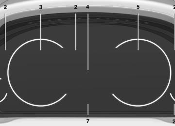
Instrument cluster Overview, instrument cluster
1 Fuel gauge 84
2 Speedometer 3 Indicator/warning lamps 81
4 Tachometer 845 Engine oil temperature 84
6 Electronic displays 77
7 Display/reset miles 84Online Edition for Part no. 01 40 2 903 008 - 07 12 490
75
Controls
Displays
Overview, instrument cluster with enhanced features
1 Fuel gauge 84
2 Speedometer 3 Indicator/warning lamps 81
4 Tachometer 845 Engine oil temperature 84
6 Electronic displays 77
7 Display/reset miles 8476
Online Edition for Part no. 01 40 2 903 008 - 07 12 490
Displays
Controls
Electronic displays Overview, instrument cluster
1 Miles/trip miles 84
External temperature 84
Time 84
Date 84
Range 85
Selection list, such as for the radio 88
Navigation display, see user's manual for Navigation, Entertainment and Communi‐ cation. Computer 88Speed limit detection 86
2 Transmission display 74Current fuel consumption 85
Energy recovery 853 Service requirements 85
Messages, e.g. Check Control 81
Navigation display, see user's manual for Navigation, Entertainment and Communi‐ cation.Online Edition for Part no. 01 40 2 903 008 - 07 12 490
77
Controls
Displays
Overview, instrument cluster with enhanced features
1 Messages, e.g. Check Control 81
Time 84
Date 84
2 Range 85
3 Computer 88Speed limit detection 86
4 Navigation display
Service requirements 85
Miles/trip miles 845 Selection list, such as for the radio 88
Current fuel consumption 85
Energy recovery 85
External temperature 84
Transmission display 74Multifunctional instrument display The concept The instrument dispaly is a variable display. When the driving mode is changed, the appear‐
ance is changed to reflect the new driving mode. The change of appearance can be deactivated in the Control Display. Some of the displays in the instrument display may differ from the way they are shown in this owner's manual.
78
Online Edition for Part no. 01 40 2 903 008 - 07 12 490
At a glance
Displays