- Download PDF Manual
-
After the engine starts, accelerate as usual. Safety mode After the engine switches off automatically, it will not start again automatically if any one of the following conditions are met. ▷ The driver's safety belt is unbuckled and the
driver's door is open.
▷ The hood was unlocked. Some indicator lamps light up for varying lengths of time. The engine can only be started via the Start/ Stop button.
Note Even if driving away was not intended, the de‐ activated engine starts up automatically in the following situations: ▷ Excessive warming of the passenger com‐
partment when the cooling function is switched on.
▷ The steering wheel is turned. ▷ Automatic transmission: the transmission position is changed from D to N, R, or M/S. ▷ Automatic transmission: the transmission position is changed from P to N, D, R, or M/ S.
▷ The vehicle begins rolling. ▷ Fogging of the windows when the automatic
climate control is switched on.
▷ The vehicle battery charge is very low. ▷ Excessive cooling of the passenger com‐ partment when the heating is switched on. ▷ Low brake vacuum pressure; this can occur, for example, if the brake pedal is depressed a number of times in succession.
Activating/deactivating the system manually Using the button
Press the button.
▷ LED comes on: Auto Start Stop function is
deactivated. The engine is started during an automatic engine stop.
62
Online Edition for Part no. 01 40 2 903 880 - 07 12 490
The engine can only be stopped or started via the Start/Stop button.
Releasing
Driving
Controls
▷ LED goes out: Auto Start Stop function is
activated.
Switching off the vehicle during an automatic engine stop During an automatic engine stop, the vehicle can be switched off permanently, e.g., when leaving it. 1. Press the Start/Stop button. The ignition is switched off. The Auto Start/Stop function is deactivated. Automatic transmission: the transmission position P is engaged automatically.
2. Set the parking brake. Engine start as usual via Start/Stop button. Automatic deactivation In certain situations, the Auto Start/Stop func‐ tion is deactivated automatically for safety rea‐ sons, such as when the driver is detected to be absent. Malfunction The Auto Start/Stop function no longer switches of the engine automatically. A Check Control message is displayed. It is possible to continue driving. Have the system checked.
Parking brake Applying The lever automatically engages after being pulled up.
The indicator lamp lights up red. The parking brake is set. Lower lamp: indicator lamp in Canadian models
Raise lever slightly, press the button and guide the lever down. Notes
Use while driving If on a rare occasion it is necessary to use the parking brake while driving, do not use ex‐ cessive force when applying it. When using it, keep the button on the lever depressed. Otherwise, using excessive force when applying the parking brake may cause the rear wheels to lock, resulting in fishtailing.◀ To prevent corrosion and braking control on one side only, lightly apply the parking brake period‐ ically while coasting, if traffic conditions permit. The brake lamps will not light up if the parking brake is engaged.
Turn signal, high beams, headlamp flasher Turn signal
Do not fold in the exterior mirrors During driving and during the operation of the turn signals/warning flashers, do not fold in the exterior mirror, or else the additional flasher lights in the exterior mirror do not have the pre‐ scribed position and can only be poorly de‐ tected.◀
Online Edition for Part no. 01 40 2 903 880 - 07 12 490
63
Controls
Driving
Using turn signals
High beams, headlamp flasher
Press the lever beyond the resistance point. To switch off manually, press the lever to the re‐ sistance point. Unusually rapid flashing of the indicator lamp in‐ dicates that a turn signal bulb has failed. Triple turn signal activation Press the lever to the resistance point. The turn signal flashes three times. The function can be activated or deactivated: 1. "Settings" 2. "Lighting" 3. "Triple turn signal"
▷ High beams, arrow 1. ▷ Headlamp flasher, arrow 2.
Washer/wiper system Switching the wipers on/off and brief wipe
Do not switch on the wipers if frozen Do not switch on the wipers if they are fro‐
zen onto the windshield; otherwise, the wiper blades and the windshield wiper motor may be damaged.◀
No wiper operation on dry windshield Do not use the windshield wipers if the
windshield is dry, as this may damage the wiper blades or cause them to become worn more quickly.◀
Switching on
Signaling briefly Press the lever to the resistance point and hold it there for as long as you want the turn signal to flash.
Press the wiper levers up. The lever automatically returns to its initial po‐ sition when released.
64
Online Edition for Part no. 01 40 2 903 880 - 07 12 490
▷ Normal wiping speed: press up once.
The wipers switch to intermittent operation when the vehicle is stationary.
▷ Fast wiping speed: press up twice or press
once beyond the resistance point. The wipers switch to normal speed when the vehicle is stationary.
Switching off and brief wipe
Press the wiper levers down. The lever automatically returns to its initial po‐ sition when released. ▷ Brief wipe: press down once. ▷ To switch off normal wipe: press down once. ▷ To switch off fast wipe: press down twice. Intermittent operation or rain sensor The concept The rain sensor automatically controls the time between wipes depending on the intensity of the rainfall. The sensor is located on the wind‐ shield, directly behind the interior rearview mir‐ ror.
Driving
Controls
Activating/deactivating
Press the button on the wiper lever. The LED in the steering column stalk lights up.
Deactivate the rain sensor in car washes Deactivate the rain sensor when passing through an automatic car wash; otherwise, dam‐ age could be caused by undesired wiper activa‐ tion.◀
Setting the frequency or sensitivity of the rain sensor
Turn the thumbwheel.
Clean the windshield, headlamps
Pull the lever.
Online Edition for Part no. 01 40 2 903 880 - 07 12 490
65
Controls
Driving
The system sprays washer fluid on the wind‐ shield and activates the wipers briefly. In addition, the headlamps are cleaned at regular intervals when the vehicle lights are switched on.
Do not use the washer system at freezing temperatures
Do not use the washers if there is any danger that the fluid will freeze on the windshield; oth‐ erwise, your vision could be obscured. For this reason, use antifreeze. Avoid using the washer when the reservoir is empty; otherwise, you could damage the pump.◀
Windshield washer nozzles The windshield washer nozzles are automati‐ cally heated while the ignition is switched on. Fold-out position of the wipers Required when changing the wiper blades or under frosty conditions, for example. 1. Switch off the ignition. 2. Under frosty conditions, ensure that the
wiper blades are not frozen onto the wind‐ shield.
3. Press the wiper lever up beyond the point of resistance and hold it for approx. 3 seconds, until the wiper remains in a nearly vertical position.
After the wipers are folded back down, the wiper system must be reactivated.
Fold the wipers back down Before switching the ignition on, fold the wipers back down to the windshield; otherwise, the wipers may become damaged when they are switched on.◀ 1. Switch on the ignition. 2. Press the wiper levers down. The wipers
move to their resting position and are ready for operation.
Washer fluid General information
Antifreeze for washer fluid Antifreeze is flammable. Therefore, keep
it away from sources of ignition. Only keep it in the closed original container and inaccessible to children. Follow the instructions on the container.◀
Washer fluid reservoir Adding washer fluid Only add washer fluid when the engine is
cool, and then close the cover completely to avoid contact between the washer fluid and hot engine parts. Otherwise, there is the danger of fire and a risk to personal safety if the fluid is spilled.◀
All washer nozzles are supplied from one reser‐ voir. Fill with water and – if required – with a washer antifreeze, according to the manufacturer's rec‐ ommendations. Mix the washer fluid before adding to maintain the correct mixing ratio. For the capacity, refer to technical data.
66
Online Edition for Part no. 01 40 2 903 880 - 07 12 490
Manual transmission Shifting
Shifting into 5th or 6th gear When shifting into 5th or 6th gear, push the gearshift lever to the right; otherwise inad‐ vertent shifting into the 3rd or 4th gear could lead to engine damage.◀
Reverse gear Select only when the vehicle is stationary. When the gearshift lever is pressed to the left, a slight resistance needs to be overcome.
Automatic transmission with Steptronic Transmission positions D Drive, automatic position Position for normal vehicle operation. All for‐ ward gears are available. R is Reverse Select only when the vehicle is stationary. N is Neutral Use in automatic car washes, for example. The vehicle can roll. When the ignition is switched off, refer to page 59, position P is engaged automatically. P Park Select only when the vehicle is stationary. The drive wheels are blocked. P is engaged automatically: ▷ After the engine is switched off when the
vehicle is in radio ready state, refer to page 60, or when the ignition is switched off, refer to page 59, and when position R or D is engaged.
Driving
Controls
▷ With the ignition is off, if position N is en‐
gaged.
▷ If the safety belt is unbuckled, the driver's door is opened, and the brake pedal is not pressed while the vehicle is stationary and transmission position R or D is engaged.
Before exiting the vehicle, make sure that posi‐ tion P of the automatic transmission is engaged. Otherwise, the vehicle may begin to roll. Kickdown Kickdown is used to achieve maximum driving performance. Press on the gas pedal beyond the resistance point at the full throttle position. Engaging the transmission position ▷ Transmission position P can only be disen‐ gaged if the engine is running and the brake pedal is pressed.
▷ With the vehicle stationary, press on the brake pedal before shifting out of P or N; otherwise, the shift command will not be executed: shift lock.
Depress the brake until you start driv‐ ing
To prevent the vehicle from creeping after you select a driving position, maintain pres‐ sure on the brake pedal until you are ready to start.◀
Engaging D, R and N
Briefly push the selector lever in the desired di‐ rection, beyond a resistance point if necessary.
Online Edition for Part no. 01 40 2 903 880 - 07 12 490
67
Controls
Driving
After releasing the selector lever, it returns to its center position.
Press unlock button, in order to: ▷ Engage R. ▷ Shift out of P.
Engaging P
Press button P.
Sport program DS and manual mode M/ Activating the sport program
Push the selector lever to the left out of trans‐ mission position D.
DS is displayed in the instrument cluster. The sport program of the transmission is acti‐ vated.
Activating the M/S manual mode 1. Push the selector lever to the left out of
transmission position D.
2. Push the selector lever forward or backward. Manual mode becomes active and the gear is changed. The engaged gear is displayed in the instrument cluster, e.g., M1. Once maximum engine speed is attained, M/S manual mode is automatically upshifted as needed. Switching to manual mode ▷ To shift down: press the selector lever for‐
ward.
▷ To shift up: pull the selector lever rearwards. Gears will only be shifted at appropriate engine and road speeds, e.g., downshifting is not pos‐ sible if the engine speed is too high. The selected gear is briefly displayed in the in‐ strument cluster, followed by the current gear. Sport automatic transmission: prevent automatic upshifting in M/S manual mode For vehicles with Sport automatic transmis‐ sions, automatic shift operations are not per‐ formed, at maximum engine speed for example, if one of the following conditions is met: ▷ DSC deactivated. ▷ TRACTION activated. ▷ SPORT+ activated. In addition, the kickdown is deactivated. Ending the sport program/manual mode Push the selector lever to the right.
68
Online Edition for Part no. 01 40 2 903 880 - 07 12 490
Driving
Controls
D is displayed in the instrument cluster. Shift paddles for Sport automatic transmission
The shift paddles on the steering wheel allow you to shift gears quickly while keeping both hands on the steering wheel. If the shift paddles on the steering wheel are used to shift gears in automatic mode, the trans‐ mission temporarily switches to manual mode. If the shift paddles are not used and the vehicle is not accelerated for a certain time, the system switches back into automatic mode if the selec‐ tor lever is in transmission position D. ▷ Shift up: pull right shift paddle. ▷ Shift down: pull left shift paddle. The vehicle only shifts up or down at appropriate engine and road speeds, e.g., it does not shift down if the engine speed is too high. The selected gear is briefly displayed in the in‐ strument cluster, followed by the current gear.
Displays in the instrument cluster
The transmission position is dis‐ played, e.g.: P.
Online Edition for Part no. 01 40 2 903 880 - 07 12 490
69
Controls
Displays
Displays Vehicle equipment All standard, country-specific and optional equipment that is offered in the model series is described in this chapter. Therefore, equipment
Instrument cluster Overview, instrument cluster
is also described that is not available in a vehicle, e. g., because of the selected optional equip‐ ment or country variant. This also applies for safety-related functions and systems.
1 Fuel gauge 76
2 Speedometer 3 Indicator/warning lamps 74
4 Tachometer 765 Engine oil temperature 76
6 Current fuel consumption 77
7 Electronic displays 72
8 Display/reset miles 7670
Online Edition for Part no. 01 40 2 903 880 - 07 12 490
Overview, instrument cluster with enhanced features
Displays
Controls
1 Fuel gauge 76
2 Speedometer 3 Indicator/warning lamps 74
4 Tachometer 765 Engine oil temperature 76
6 Current fuel consumption 77
7 Electronic displays 72
8 Display/reset miles 76Online Edition for Part no. 01 40 2 903 880 - 07 12 490
71
Controls
Displays
Electronic displays Overview, instrument cluster
1 Messages, e.g. Check Control 73
Time 76
Date 76
External temperature 76
Selection lists 81
Service requirements 77Miles/trip miles 76
Computer 812 Transmission display 69
Gear shift indicator 79
3 Status, Driving Experience Switch 113
72
Online Edition for Part no. 01 40 2 903 880 - 07 12 490
Overview, instrument cluster with enhanced features
Displays
Controls
Navigation display, see user's manual for Navigation, Entertainment and Communi‐ cation.
2 Energy recovery 77
Transmission display 69
Current fuel consumption 77
ECO PRO 1673 Messages, e.g. Check Control 73
Service requirements 77
In addition, an acoustic signal may be output and a text message may appear on the Control Dis‐ play.
1 Time 76
External temperature 76
Date 76
Selection list, such as for the radio 81
Speed limit detection 79
Computer 81
Miles/trip miles 76Check Control The concept The Check Control system monitors functions in the vehicle and notifies you of malfunctions in the monitored systems. A Check Control message is displayed as a combination of indicator or warning lamps and text messages in the instrument cluster and in the Head-up Display.
Online Edition for Part no. 01 40 2 903 880 - 07 12 490
73
Controls
Displays
Indicator/warning lamps
The indicator and warning lamps can light up in a variety of combinations and colors. Several of the lamps are checked for proper functioning and light up temporarily when the engine is started or the ignition is switched on.
Overview: indicator/warning lamps
Symbol Function or system
Turn signal
Front fog lamps
Rear fog lamp
High beams
High-beam Assistant
Parking lamps, headlamp control
Active Cruise Control
Vehicle detection, Active Cruise Control
Symbol Function or system
Collision warning
Adjustable speed limit
Cruise control
Lane departure warning
DSC Dynamic Stability Control
DSC Dynamic Stability Control is de‐ activated or DTC Dynamic Traction Control is activated Tire Pressure Monitor Flat Tire Monitor Safety belts
Airbag system
Steering system
Emissions
Parking brake Brake system In Canadian models Parking brake Brake system ABS Antilock Brake System
74
Online Edition for Part no. 01 40 2 903 880 - 07 12 490
Symbol Function or system
Hiding Check Control messages
Displays
Controls
ABS Antilock Brake System in Cana‐ dian models
At least one Check Control message is displayed or is stored (symbol in display)
Text messages Text messages in combination with a symbol in the instrument cluster explain a Check Control message and the meaning of the indicator and warning lamps. Supplementary text messages Addition information, such as on the cause of a fault or the required action, can be called up via Check Control. The supplementary text of urgent messages is displayed on the Control Display automatically. Symbols Depending on the Check Control message, the following functions can be selected. ▷
"Owner's Manual"
Display additional information about the Check Control message in the integrated owner's manual.
▷
▷
"Service request"
Contact the service partner. "Roadside Assistance"
Contact Roadside Assistance.
Press the computer button on the turn signal lever. ▷ Some Check Control messages are dis‐
played continuously and are not cleared un‐ til the malfunction is eliminated. If several malfunctions occur at once, the messages are displayed consecutively. These messages can be hidden for approx. 8 seconds. After this time, they are dis‐ played again automatically.
▷ Other Check Control messages are hidden
automatically after approx. 20 seconds. They are stored and can be displayed again later.
"Check Control"
Displaying stored Check Control messages 1. "Vehicle Info" 2. "Vehicle status" 3. 4. Select the text message. Messages after trip completion Special messages that are displayed during driving are displayed again after the ignition is switched off.
Online Edition for Part no. 01 40 2 903 880 - 07 12 490
75
Controls
Displays
Fuel gauge
The vehicle inclination may cause the display to vary. Notes on refueling, refer to page 172.
Tachometer Always avoid engine speeds in the red warning field. In this range, the fuel supply is interrupted to protect the engine.
Engine oil temperature
▷ Cold engine: the pointer is at
the low temperature end. Drive at moderate engine and vehicle speeds.
▷ Normal operating tempera‐ ture: the pointer is in the mid‐ dle or in the left half of the temperature display.
▷ Hot engine: the pointer is at the high tem‐ perature end. A Check Control message is displayed in addition.
Display/reset miles
Press the knob. ▷ When the ignition is switched off, the time, external temper‐ ature and odometer are dis‐ played.
▷ When the ignition is switched on, the trip
odometer is reset.
External temperature External temperature warning If the indicator drops to +37 ℉/+3 ℃, a signal sounds. A Check Control message is dis‐ played. There is an increased risk of ice
on roads.
Ice on roads Even at temperatures above +37 ℉/+3 ℃,
there can be a risk of ice on roads. Therefore, drive carefully on bridges and shaded roads, for example, to avoid the increased risk of an accident.◀
Coolant temperature If the coolant along with the engine becomes too hot, a Check Control message is displayed. Check the coolant level, refer to page 192.
Odometer and trip odometer
▷ Odometer, arrow 1. ▷ Trip odometer, arrow 2.
Time
Date
The time is displayed at the bot‐ tom of the instrument cluster. Setting the time and time format, refer to page 84.
The date is displayed in the in‐ strument cluster. Setting the date and date format, refer to page 84.
76
Online Edition for Part no. 01 40 2 903 880 - 07 12 490
Range
After the reserve range is reached: ▷ A Check Control message is
displayed briefly.
▷ The remaining range is
shown on the onboard com‐ puter.
▷ When a dynamic driving style is used, such as when cornering quickly, operation of the engine is not always ensured.
The Check Control message appears continu‐ ously below a range of approx. 30 miles/50 km.
Refuel promptly Refuel no later than at a range of
30 miles/50 km, or operation of the engine is not ensured and damage may occur.◀
Displaying the cruising range 1. "Settings" 2. "Info display" 3. "Additional indicators" The range is displayed in the instrument cluster.
Current fuel consumption Instrument cluster
Displays the current fuel con‐ sumption. You can check whether you are currently driving in an efficient and environmen‐ tally-friendly manner.
Instrument cluster with enhanced features
Displays the current fuel con‐ sumption. You can check whether you are currently driving
Displays
Controls
in an efficient and environmentally-friendly manner.
Displaying the current fuel consumption 1. "Settings" 2. "Info display" 3. "Additional indicators" The bar display for the current fuel consumption is displayed in the instrument cluster.
Energy recovery
The kinetic energy of the vehicle is converted to electrical energy while coasting. The vehicle bat‐ tery is partially charged and fuel consumption can be reduced.
Service requirements The concept The driving distance or the time to the next serv‐ ice is displayed briefly after the ignition is switched on. The current service requirements can be read out from the remote control by the service spe‐ cialist. Display Data regarding the service status or legally man‐ dated inspections of the vehicle are automati‐ cally transmitted to your service center before a service due date. Instrument cluster
Display in the instrument cluster.
Online Edition for Part no. 01 40 2 903 880 - 07 12 490
77
Controls
Displays
Instrument cluster with enhanced features
Display in the instrument cluster with expanded scope.
5. "Date:" 6. Adjust the settings. 7. Confirm.
The entered date is stored.
Automatic Service Request Data regarding the service status or legally man‐ dated inspections of the vehicle are automati‐ cally transmitted to your service center before a service due date. You can check when your service center was notified. 1. "Vehicle Info" 2. "Vehicle status" 3. Open "Options". 4. "Last Service Request" Service history Perform maintenance work at the service center and have them recorded in the vehicle data. The entries are like a service booklet of the docu‐ mentation of regular maintenance. The entered maintenance work can be dis‐ played on the Control Display. Function is avail‐ able as soon as a maintenance operation has been entered in the vehicle data. 1. "Vehicle Info" 2. "Vehicle status" 3. 4.
"Service required"
"Service history"
Performed maintenance operations are dis‐ played.
5. Select an entry to call up detailed informa‐
tion.
Detailed information on service requirements More information on the scope of service re‐ quired can be displayed on the Control Display. 1. "Vehicle Info" 2. "Vehicle status" 3.
"Service required"
Required maintenance procedures and le‐ gally mandated inspections are displayed. 4. Select an entry to call up detailed informa‐
tion.
Symbols
Symbols
Description No service is currently required.
The deadline for service or a le‐ gally mandated inspection is approaching. The service deadline has al‐ ready passed.
Entering appointment dates Enter the dates for the required inspections. Ensure that the vehicle date and time are set correctly. 1. "Vehicle Info" 2. "Vehicle status" 3. 4. "§ Vehicle inspection"
"Service required"
78
Online Edition for Part no. 01 40 2 903 880 - 07 12 490
Symbols
Symbols
Description Green: maintenance was per‐ formed on schedule.
Yellow: maintenance was per‐ formed late.
Maintenance was not per‐ formed.
Gear shift indicator The concept The system recommends the most fuel efficient gear in the current driving situation. Displays Indicators to shift up or down are displayed in the instrument cluster. Symbols Description
Fuel efficient gear is engaged.
Shift up to fuel efficient gear.
Shift down to fuel efficient gear.
Shift into neutral.
Displays
Controls
Speed limit detection with No Passing Information The concept Speed limit detection Speed limit detection uses a symbol in the shape of a traffic sign to display the currently detected speed limit. The camera at the base of the interior rearview mirror detects traffic signs at the edge of the road as well as variable over‐ head sign posts. Traffic signs with extra symbols for wet road conditions, etc. are also detected and compared with vehicle interior data, such as for the rain sensor, and are displayed depending on the situation. The system takes into account the information stored in the navigation system and also displays speed limits present on routes without signs. No Passing Information No Passing Information displays in the instru‐ ment cluster the beginnings and ends of no passing zones detected by the camera. The sys‐ tem accounts for only the beginnings and ends of No Passing zones marked by signs. No display is shown: ▷ In countries where No Passing zones are
primarily identified with road markings.
▷ On routes without signage. ▷ Where there are railroad crossings, highway markings or other situations where no sig‐ nage is present, but passing would not be permitted.
Notes
Personal judgment The system cannot serve as a substitute for the driver's personal judgment of the traffic situation. The system assists the driver and does not re‐ place the human eye.◀
Online Edition for Part no. 01 40 2 903 880 - 07 12 490
79
Controls
Displays
At a glance Camera
The camera is located near the base of the mir‐ ror. Keep the windshield in the area behind the in‐ terior rear view mirror clean and clear.
Switching on/off 1. "Settings" 2. "Info display" 3. "Speed limit information" If speed limit detection is switched on, it can be displayed on the info display in the instrument cluster via the onboard computer. No Passing Information is displayed together with activated speed limit information. Display The following is displayed in the instrument cluster. Speed limit detection
Current speed limit.
Speed limit detection is not avail‐ able.
Speed limit detection can also be displayed in the Head-up Display. No Passing Information
▷ Start of No Passing zone. ▷ End of No Passing zone. ▷ No Passing Information not
available.
No Passing Information can also be displayed in the Head-up Display. System limits The system may not be fully functional and may provide incorrect information in the following situations: ▷ In heavy fog, rain or snowfall. ▷ When signs are concealed by objects. ▷ When driving very close to the vehicle in
front of you.
▷ When driving toward bright lights. ▷ When the windshield behind the interior
rearview mirror is fogged over, dirty or cov‐ ered by a sticker, etc.
▷ In the event of incorrect detection by the
camera.
▷ If the speed limits stored in the navigation
system are incorrect.
▷ In areas not covered by the navigation sys‐
tem.
▷ When roads differ from the navigation, such
as due to changes in the road network.
▷ When passing buses or trucks with a speed
sticker.
▷ If the traffic signs are non-conforming. ▷ During calibration of the camera immedi‐
ately after vehicle shipment.
80
Online Edition for Part no. 01 40 2 903 880 - 07 12 490
Selection lists in the instrument cluster The concept The following can be displayed or operated us‐ ing the buttons and the thumbwheel on the steering wheel and the display in the instrument cluster: ▷ Current audio source. ▷ Redial on telephone. ▷ Activation of the voice activation system. In addition, programs of the Driving Experience Switch are displayed. Display Instrument cluster
Instrument cluster with enhanced features
Displays
Controls
Activating a list and adjusting the setting
On the right side of the steering wheel, turn the thumbwheel to activate the corresponding list. Using the thumbwheel, select the desired set‐ ting and confirm it by pressing the thumbwheel.
Computer Indication in the info display
The information from the on‐ board computer is shown in the info display in the instrument cluster.
Calling up information on the info display
Press the onboard computer button on the turn signal lever. Information is displayed on the info display of the instrument cluster.
Online Edition for Part no. 01 40 2 903 880 - 07 12 490
81
Controls
Displays
Information at a glance Repeatedly pressing the button on the turn sig‐ nal lever calls up the following information on the info display: ▷ Range. ▷ Average fuel consumption. ▷ Current fuel consumption. ▷ Average speed. ▷ Date. ▷ Speed limit detection. ▷ Time of arrival.
When destination guidance is activated in the navigation system. ▷ Distance to destination.
When destination guidance is activated in the navigation system.
▷ Arrow view of navigation system.
When destination guidance is activated in the navigation system. When the arrow view in the Head-up Display is inactive.
▷ ECO PRO bonus range. Adjusting the info display You can select what information from the on‐ board computer is to be displayed on the info display of the instrument cluster. 1. "Settings" 2. "Info display" 3. Select the desired displays. Information in detail Range Displays the estimated cruising range available with the remaining fuel. It is calculated based on your driving style over the last 20 miles/30 km. If there is only enough fuel left for less than 45 miles/80 km, the color of the display changes.
Average fuel consumption This is calculated for the period during which the engine is running. The average fuel consumption is calculated on the basis of various distances. Average speed Periods in which the vehicle is parked with the engine manually stopped do not enter into the calculation of the average speed. Resetting average values Press and hold the computer button on the turn signal lever. Distance to destination The distance remaining to the destination is dis‐ played if a destination is entered in the naviga‐ tion system before the trip is started. The distance to the destination is adopted au‐ tomatically. Time of arrival
The estimated time of arrival is displayed if a destination is en‐ tered in the navigation system before the trip is started. The time must be correctly set.
Speed limit detection Description of the speed limit detection, refer to page 79, function. Speed limit Display of a speed limit which, when reached, should cause a warning to be issued. The warning is repeated if the vehicle speed drops below the set speed limit once by at least 3 mph/5 km/h.
82
Online Edition for Part no. 01 40 2 903 880 - 07 12 490
Displaying, setting or changing the limit 1. "Settings" 2. "Speed" 3. "Warning at:"
Displays
Controls
Resetting the trip computer 1. "Vehicle Info" 2. "Trip computer" 3. "Reset": all values are reset.
"Automatically reset": all values are reset approx. 4 hours after the vehicle comes to a standstill.
4. Turn the controller until the desired limit is
displayed.
5. Press the controller. The speed limit is stored. Activating/deactivating the limit 1. "Settings" 2. "Speed" 3. "Warning" 4. Press the controller. Setting your current speed as the limit 1. "Settings" 2. "Speed" 3. "Select current speed" 4. Press the controller.
The current vehicle speed is stored as the limit.
Trip computer The vehicle features two types of computer. ▷ "Onboard info": the values can be reset as
often as necessary.
▷ "Trip computer": the values provide an over‐
view of the current trip.
Display on the Control Display Display the onboard computer or trip computer on the Control Display. 1. "Vehicle Info" 2. "Onboard info" or "Trip computer" Resetting the fuel consumption or speed 1. "Vehicle Info" 2. "Onboard info" 3. "Cons." or "Speed"
4. "Yes"
Online Edition for Part no. 01 40 2 903 880 - 07 12 490
83
Controls
Displays
Sport displays In the Control Display, the current values for power and torque can be displayed. Displaying sport displays in the Control Display 1. "Vehicle Info" 2. "Sport displays"
Settings on the Control Display Time Setting the time zone 1. "Settings" 2. "Time/Date" 3. "Time zone" 4. Select the desired time zone. The time zone is stored. Setting the time 1. "Settings" 2. "Time/Date" 3. "Time:"
The time is stored. Setting the time format 1. "Settings" 2. "Time/Date" 3. "Format:" 4. Select the desired format. The time format is stored. Date Setting the date 1. "Settings" 2. "Time/Date" 3. "Date:" 4. Turn the controller until the desired day is
displayed.
5. Press the controller. 6. Make the necessary settings for the month
and year.
The date is stored. Setting the date format 1. "Settings" 2. "Time/Date" 3. "Format:" 4. Select the desired format.
4. Turn the controller until the desired hours
are displayed.
5. Press the controller. 6. Turn the controller until the desired minutes
are displayed.
7. Press the controller.
The date format is stored.
84
Online Edition for Part no. 01 40 2 903 880 - 07 12 490
Displays
Controls
Language Setting the language To set the language on the Control Display: 1. "Settings" 2. "Language/Units" 3. "Language:"
Brightness Setting the brightness To set the brightness of the Control Display: 1. "Settings" 2. "Control display" 3. "Brightness"
4. Select the desired language. The setting is stored for the remote control cur‐ rently in use. Units of measure Setting the units of measure To set the units for fuel consumption, route/dis‐ tance and temperature: 1. "Settings" 2. "Language/Units" 3. Select the desired menu item.
4. Turn the controller until the desired bright‐
ness is set.
5. Press the controller. The setting is stored for the remote control cur‐ rently in use. Depending on the light conditions, the bright‐ ness control may not be clearly visible. Assist system information Display on the Control Display Information on the Assist system can be dis‐ played by activating Assist on the Control Dis‐ play. 1. "Settings" 2. "Control display"
4. Select the desired unit. The setting is stored for the remote control cur‐ rently in use.
Online Edition for Part no. 01 40 2 903 880 - 07 12 490
85
Controls
Displays
3. "Driver assistance info"
86
Online Edition for Part no. 01 40 2 903 880 - 07 12 490
Lamps Vehicle equipment All standard, country-specific and optional equipment that is offered in the model series is described in this chapter. Therefore, equipment is also described that is not available in a vehicle, e. g., because of the selected optional equip‐ ment or country variant. This also applies for safety-related functions and systems.
At a glance
1 Rear fog lamps 2 Front fog lamps 3 Automatic headlamp control / Adaptive
Light Control / High-beam Assistant / wel‐ come lamps / daytime running lights
4 Lamps off/daytime running lights 5 Parking lamps/daytime running lights 6 Low beams/welcome lamps / High-beam
Assistant
7 Headlamp range control 8 Instrument lighting
Lamps
Controls
: the vehicle lamps light
If the driver door is opened with the ignition switched off, the exterior lighting is automati‐ cally switched off at these switch settings. Parking lamps Switch position up on all sides, e.g., for parking. Do not use the parking lamps for extended pe‐ riods; otherwise, the battery may become dis‐ charged and it would then be impossible to start the engine. When parking, it is preferable to switch on the one-sided roadside parking lamps, refer to page 88. Low beams Switch position on: the low beams light up. Welcome lamps When parking the vehicle, leave the switch in position : the parking and interior lamps light up briefly when the vehicle is un‐ locked. Activating/deactivating 1. "Settings" 2. "Lighting" 3. "Welcome light"
with the ignition switched
or
Parking lamps/low beams, headlamp control General information Switch position: 0,
The setting is stored for the remote control cur‐ rently in use.
Online Edition for Part no. 01 40 2 903 880 - 07 12 490
87
Controls
Lamps
Headlamp courtesy delay feature The low beams stay lit for a short while if the headlamp flasher is switched on after the igni‐ tion is switched off. Setting the duration 1. "Settings" 2. "Lighting" 3. "Pathway light.: s"
or
Daytime running lights With the ignition switched on, the daytime run‐ ning lights light up in position 0, After the ignition is switched off, the parking lamps light up in position Activating/deactivating 1. "Settings" 2. "Lighting" 3. "Daytime running lamps"
4. Set the duration. The setting is stored for the remote control cur‐ rently in use. Automatic headlamp control : the low beams are switched Switch position on and off automatically, e.g., in tunnels, in twi‐ light or if there is precipitation. The indicator lamp in the instrument cluster lights up. A blue sky with the sun low on the horizon can cause the lights to be switched on. The low beams always stay on when the fog lamps are switched on.
Personal responsibility The automatic headlamp control cannot serve as a substitute for your personal judgment in determining when the lamps should be switched on in response to ambient lighting conditions. For example, the sensors are unable to detect fog or hazy weather. To avoid safety risks, you should always switch on the lamps manually un‐ der these conditions.◀
The setting is stored for the remote control cur‐ rently in use. Roadside parking lamps
The vehicle can be illuminated on one side. Switching on With the ignition switched off, press the lever either up or down past the resistance point for approx. 2 seconds. Switching off Briefly press the lever to the resistance point in the opposite direction.
88
Online Edition for Part no. 01 40 2 903 880 - 07 12 490
Lamps
Controls
situation allows. The driver can intervene at any time and switch the high beams on and off as usual. Activating
The High-beam Assistant can be activated when the low beams are switched on. 1. Turn the light switch to 2. Press the button on the turn signal lever, ar‐
or
row.
The indicator lamp in the instrument cluster lights up.
When the low beams are on, the lights are au‐ tomatically brightened or dimmed. The system responds to light from oncoming traffic and traffic driving ahead of you, and to ad‐ equate illumination, e.g., in towns and cities. The blue indicator lamp in the instru‐ ment cluster lights up when the system switches on the high beams. Depending on the version of the system in the vehicle, the high beams may not switch off for oncoming ve‐ hicles, but may only be dimmed in the areas that blind oncoming traffic. In this case, the blue in‐ dicator light will stay on.
Adaptive light control The concept Adaptive light control is a variable headlamp control system that enables dynamic illumina‐ tion of the road surface. Depending on the steering angle and other pa‐ rameters, the light from the headlamp follows the course of the road. In tight curves, e.g., on mountainous roads or when turning, one of the two front fog lamps is switched on as a turning lamp. As a result the inside of the curve is better lighted. Activating Switch position on. The turning lamps are automatically switched on depending on the steering angle or the use of turn signals. To avoid blinding oncoming traffic, the Adaptive Light Control does not swivel to the driver's side when the vehicle is at a standstill. When driving in reverse, only the turning lamp is active. Malfunction A Check Control message is displayed. Adaptive light control is malfunctioning or has failed. Have the system checked as soon as pos‐ sible.
with the ignition switched
High-beam Assistant The concept When the low beams are switched on, this sys‐ tem automatically switches the high beams on and off or suppresses the light in the areas that blind oncoming traffic. The procedure is con‐ trolled by a sensor on the front of the interior rearview mirror. The assistant ensures that the high beams are switched on whenever the traffic
Online Edition for Part no. 01 40 2 903 880 - 07 12 490
89
Controls
Lamps
Switching the high beams on and off manually
▷ When the windshield in front of the interior rearview mirror is fogged over, dirty or cov‐ ered with stickers, etc.
Camera
▷ High beams on, arrow 1. ▷ High beams off/headlamp flasher, arrow 2. The High-beam Assistant can be switched off when manually adjusting the light. To reactivate the High-beam Assistant, press the button on the turn signal lever. System limits
Personal responsibility The high-beam assistant cannot serve as a substitute for the driver's personal judgment of when to use the high beams. Therefore, man‐ ually switch off the high beams in situations where this is required to avoid a safety risk.◀ The system is not fully functional in situations such as the following, and driver intervention may be necessary: ▷ In very unfavorable weather conditions,
such as fog or heavy precipitation.
▷ In detecting poorly-lit road users, such as pedestrians, cyclists, horseback riders and wagons; when driving close to train or ship traffic; and at animal crossings.
▷ In tight curves, on hilltops or in depressions, in cross traffic or half-obscured oncoming traffic on freeways.
▷ In poorly-lit towns and cities and in the pres‐
ence of highly reflective signs.
▷ At low speeds.
The camera is located near the base of the mir‐ ror. Keep the windshield in the area behind the in‐ terior rear view mirror clean and clear.
Fog lamps Front fog lamps The parking lamps or low beams must be switched on.
Press the button. The green indicator lamp lights up.
If the automatic headlamp control, refer to page 88, is activated, the low beams will come on automatically when you switch on the front fog lamps.
Instrument lighting Adjusting
The parking lamps or low beams must be switched on to adjust the brightness. Adjust the brightness using the thumbwheel.
90
Online Edition for Part no. 01 40 2 903 880 - 07 12 490
Lamps
Controls
Selecting color scheme 1. "Settings" 2. "Lighting" 3. "Ambient:"
Interior lamps General information The interior lamps, footwell lamps, entry lamps and courtesy lamps are controlled automati‐ cally. The brightness of some of these lamps is influ‐ enced by the thumbwheel for the instrument lighting.
4. Select the desired setting. If the color scheme of the line is selected and the welcome lamps are activated, the welcome lamps are displayed in color when unlocking the vehicle. Setting the brightness The brightness of the ambient light can be ad‐ justed via the thumbwheel for the instrument lighting but also independently of it. 1. "Settings" 2. "Lighting" 3. "Brightness:" 4. Adjust the brightness.
1 Interior lamps 2 Reading lamp
Switching the interior lamps on and off
Press the button.
To switch off permanently: press the button for approx. 3 seconds. Switch back on: press button. Reading lamps
Press the button.
Reading lamps are located at the front and rear next to the interior lamps. When the interior lamps are switched off per‐ manently, the reading lamps cannot be switched on. Ambient light Depending on the equipment, the lighting can be individually adjusted in the interior for some lights.
Online Edition for Part no. 01 40 2 903 880 - 07 12 490
91
Controls
Safety
Safety Vehicle equipment All standard, country-specific and optional equipment that is offered in the model series is described in this chapter. Therefore, equipment
Airbags
is also described that is not available in a vehicle, e. g., because of the selected optional equip‐ ment or country variant. This also applies for safety-related functions and systems.
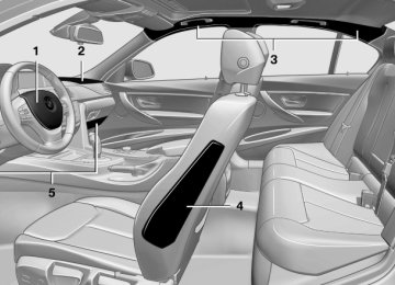
1 Front airbag, driver 2 Front airbag, front passenger 3 Head airbag
4 Side airbag 5 Knee airbags
Front airbags Front airbags help protect the driver and front passenger by responding to frontal impacts in which safety belts alone cannot provide ade‐ quate restraint. Side airbags In a lateral impact, the side airbag supports the side of the body in the chest and lap area.
Head airbags In a lateral impact, the head airbag supports the head. In the event of a rollover accident, the head air‐ bag can help to prevent the person from being thrown out of the vehicle.
92
Online Edition for Part no. 01 40 2 903 880 - 07 12 490
Knee airbag The knee airbag supports the legs in a frontal impact. Protective action Airbags are not triggered in every impact situa‐ tion, e.g., in less severe accidents or rear-end collisions.
Information on how to ensure the optimal protective effect of the airbags
▷ Keep at a distance from the airbags. ▷ Always grasp the steering wheel on the
steering wheel rim, holding your hands at the 3 o'clock and 9 o'clock positions, to keep the danger of injury to your hands or arms as low as possible if the airbag is triggered.
▷ There should be no people, animals, or ob‐
jects between an airbag and a person.
▷ Do not use the cover of the front airbag on the front passenger side as a storage area.
▷ Keep the dashboard and window on the
front passenger side clear, i.e., do not cover with adhesive labels or coverings, and do not attach holders such as for navigation instru‐ ments and mobile phones.
▷ Make sure that the front passenger is sitting correctly, i.e., keeps his or her feet and legs in the footwell; otherwise, leg injuries can occur if the front airbag is triggered.
▷ Do not place slip covers, seat cushions or other objects on the front passenger seat that are not approved specifically for seats with integrated side airbags.
▷ Do not hang pieces of clothing, such as jack‐
ets, over the backrests.
▷ Make sure that occupants keep their heads
away from the side airbag and do not rest against the head airbag; otherwise, injuries can occur if the airbags are triggered.
▷ Do not remove the airbag restraint system. ▷ Do not remove the steering wheel.
Safety
Controls
▷ Do not apply adhesive materials to the air‐
bag cover panels, cover them or modify them in any way.
▷ Never modify either the individual compo‐ nents or the wiring in the airbag system. This also applies to steering wheel covers, the dashboard, the seats, the roof pillars and the sides of the headliner.◀
Even when all instructions are followed closely, injury from contact with the airbags cannot be ruled out in certain situations. The ignition and inflation noise may lead to short-term and, in most cases, temporary hear‐ ing impairment in sensitive individuals.
In the case of a malfunction, deactivation and after triggering of the airbags
Do not touch the individual components imme‐ diately after the system has been triggered; oth‐ erwise, there is the danger of burns. Only have the airbags checked, repaired or dis‐ mantled and the airbag generator scrapped by your service center or a workshop that has the necessary authorization for handling explosives. Non-professional attempts to service the sys‐ tem could lead to failure in an emergency or un‐ desired triggering of the airbag, either of which could result in injury.◀ Warnings and information on the airbags are also found on the sun visors. Functional readiness of the airbag system
When the ignition is switch on, the warn‐ ing lamp in the instrument cluster lights up briefly and thereby indicates the op‐ erational readiness of the entire airbag system and the belt tensioner.
Airbag system malfunctioning ▷ Warning lamp does not come on when the
ignition is turned on.
▷ The warning lamp lights up continuously.
Online Edition for Part no. 01 40 2 903 880 - 07 12 490
93
Controls
Safety
When there is a malfunction, have the air‐ bag system checked immediately
When there is a malfunction, have the airbag system checked immediately; otherwise, there is a risk that the system does not function as ex‐ pected in the event of an accident despite cor‐ responding severity of the accident.◀
Automatic deactivation of the front passenger airbags The system determines whether the front pas‐ senger seat is occupied by measuring the re‐ sistance of the human body. The front, knee, and side airbag on the front passenger side are activated or deactivated ac‐ cordingly.
Leave feet in the footwell Make sure that the front passenger keeps his or her feet in the footwell; otherwise, the front passenger airbags may not function properly.◀
Child restraint fixing system in the front passenger seat
Before transporting a child on the front passen‐ ger seat, see the safety notes and instructions under Children on the front passenger seat.◀
Malfunction of the automatic deactivation system When transporting older children and adults, the front passenger airbags may be deactivated in certain sitting positions. In this case, the indica‐ tor lamp for the front passenger airbags lights up. In this case, change the sitting position so that the front passenger airbags are activated and the indicator lamp goes out. If it is not possible to activate the airbags, have the person sit in the rear. To make sure that the occupied seat cushion can be evaluated correctly ▷ Do not attach covers, cushions, ball mats or other items to the front passenger seat un‐
less they are specifically recommended by the manufacturer of your vehicle.
▷ Do not place any electronic devices on the passenger seat if a child restraint system is to be installed on it.
▷ Do not place objects under the seat that could press against the seat from below. Indicator lamp for the front passenger airbags
The indicator lamp for the front passenger air‐ bags indicates the operating state of the front passenger airbags. The lamp indicates whether the airbags are ac‐ tivated or deactivated.
▷ The indicator lamp lights up when a child who is properly seated in a child restraint fix‐ ing system intended for that purpose is detected on the seat or the seat is empty. The airbags on the front passen‐ ger side are not activated.
▷ The indicator lamp does not light up when,
for example, a correctly seated person of sufficient size is detected on the seat. The airbags on the front passenger side are ac‐ tivated.
Detected child seats The system generally detects children seated in a child seat, especially in the child seats that were required by NHTSA when the vehicle was manufactured. After installing a child seat, make
94
Online Edition for Part no. 01 40 2 903 880 - 07 12 490
sure that the indicator lamp for the front pas‐ senger airbags lights up. This indicates that the child seat has been detected and the front pas‐ senger airbags are not activated. Strength of the driver's and front passenger airbag The strength with which the driver's and front passenger airbags are triggered depends on the position of the driver's and front passenger seats. To maintain the accuracy of this function over the long-term, calibrate the front seats when a corresponding message appears on the Control Display. Calibrating the front seats A corresponding message appears on the Con‐ trol Display. 1. Move the respective seat forward all the
way.
2. Move the respective seat forward again. It
moves forward briefly.
3. Readjust the seat to the desired position. The calibration procedure is completed when the message on the Control Display disappears. If the message continues to be displayed, repeat the calibration. If the message does not disappear after a repeat calibration, have the system checked as soon as possible.
Unobstructed area of movement Ensure that the area of movement of the seats is unobstructed to avoid personal injury or damage to objects.◀
Tire Pressure Monitor TPM The concept The tire inflation pressure is measured in the four mounted tires. The system notifies you if
Safety
Controls
there is a significant loss of pressure in one or more tires. Functional requirements The system must have been reset when the in‐ flation pressure was correct; otherwise, reliable signaling of a flat tire is not ensured. Always use wheels with TPM electronics to ensure that the system will operate properly. Reset the system after each correction of the tire inflation pres‐ sure and after every tire or wheel change. System limits
Sudden tire damage Sudden serious tire damage caused by external influences cannot be indicated in ad‐ vance.◀ The system does not operate correctly if it has not been reset. For example, a flat tire may be indicated despite correct tire inflation pres‐ sures. The system is inactive and cannot indicate a flat tire: ▷ For a mounted wheel without TPM electron‐
ics.
▷ When the TPM is disturbed by other sys‐ tems or devices with the same radio fre‐ quency.
Status display The current status of the Tire Pressure Monitor TPM can be displayed on the Control Display, e.g., whether or not the TPM is active. 1. "Vehicle Info" 2. "Vehicle status" 3. The status is displayed. Status display The tire and system status is indicated by the color of the tires.
"Tire Pressure Monitor - TPM"
Online Edition for Part no. 01 40 2 903 880 - 07 12 490
95
Controls
Safety
A change in the tire inflation pressure during driving is taken into account. A correction is only necessary if this is indicated by the TPM Wheels, green The tire inflation pressure is equal to the target state. One wheel is yellow A flat tire or major drop in inflation pressure in the indicated tire. All wheels are yellow ▷ A flat tire or major drop in inflation pressure
in several tires.
▷ The system was not reset after a wheel
change and thus warns based on the infla‐ tion pressures initialized last.
▷ A flat tire in one or more tires while the sys‐
tem is being reset.
Wheels, gray The system cannot detect a flat tire. Reasons for this may be: ▷ TPM is being reset. ▷ Disturbance by systems or devices with the
same radio frequency.
▷ Malfunction. Resetting the system Reset the system after each correction of the tire inflation pressure and after every tire or wheel change. 1. "Vehicle Info" 2. "Vehicle status" 3. 4. Start the engine - do not drive away. 5. Reset the tire pressure using "Reset". 6. Drive away.
"Reset"
The tires are shown in gray and "Resetting TPM..." is displayed. After driving for a few minutes, the set tire infla‐ tion pressures are applied as set values. The re‐ setting process is completed automatically dur‐ ing driving. The tires are shown in green and "TPM active" is shown on the Control Display. The trip can be interrupted at any time. If you drive away again, the process resumes auto‐ matically. If a flat tire is detected during a reset, all tires are displayed in yellow. Low tire pressure message
The yellow warning lamp lights up. A Check Control message is displayed. ▷ There is a flat tire or a major loss in
tire inflation pressure.
▷ The system was not reset after a wheel
change and thus warns based on the infla‐ tion pressures initialized last.
1. Reduce your speed and stop cautiously.
Avoid sudden braking and steering maneu‐ vers.
2. Check whether the vehicle is fitted with reg‐
ular tires or run-flat tires. Run-flat tires, refer to page 185, are labeled with a circular symbol containing the letters RSC marked on the tire sidewall.
Do not continue driving without run-flat tires
Do not continue driving if the vehicle is not equipped with run-flat tires; continued driving may result in serious accidents.◀ When a low inflation pressure is indicated, DSC Dynamic Stability Control is switched on if nec‐ essary. Actions in the event of a flat tire Normal tires 1.
Identify the damaged tire.
96
Online Edition for Part no. 01 40 2 903 880 - 07 12 490
Do this by checking the air pressure in all four tires. If the tire inflation pressure in all four tires is correct, the Tire Pressure Monitor may not have been initialized. In this case, initialize the system. If an identification is not possible, please contact the service center.
2. Rectify the flat tire.
Use of tire sealant, e.g., the Mobility System, may damage the TPM wheel electronics. In this case, have the electronics checked at the next opportunity and have them re‐ placed if necessary.
Run-flat tires Maximum speed You can continue driving with a damaged tire at speeds up to 50 mph/80 km/h.
Continued driving with a flat tire If continuing to drive with a damaged tire: 1. Avoid sudden braking and steering maneu‐
vers.
2. Do not exceed a speed of 50 mph/80 km/h. 3. Check the air pressure in all four tires at the
next opportunity. If the tire inflation pressure in all four tires is correct, the Tire Pressure Monitor may not have been initialized. In this case, initialize the system.
Possible driving distance with complete loss of tire inflation pressure: The possible driving distance after a loss of tire inflation pressure depends on the cargo load and the driving style and conditions. For a vehicle containing an average load, the possible driving distance is approx. 50 miles/80 km. When the vehicle is driven with a damaged tire, its handling characteristics change, e.g., re‐
Safety
Controls
duced lane stability during braking, a longer braking distance, and altered self-steering properties. Adjust your driving style accord‐ ingly. Avoid abrupt steering maneuvers or driv‐ ing over obstacles, e.g., curbs, potholes, etc. Because the possible driving distance depends on how the vehicle is used during the trip, the actual distance may be smaller or greater de‐ pending on the driving speed, road conditions, external temperature, cargo load, etc. Continued driving with a flat tire Drive moderately and do not exceed a
speed of 50 mph/80 km/h. A loss of tire inflation pressure results in a change in the handling characteristics, e.g., re‐ duced lane stability during braking, a longer braking distance and altered self-steering prop‐ erties.◀
Final tire failure Vibrations or loud noises while driving can indicate the final failure of the tire. Reduce speed and stop; otherwise, pieces of the tire could come loose and cause an accident. Do not con‐ tinue driving, and contact your service center.◀
Message when the system was not