- Download PDF Manual
-
2 Locking 3 Opening the trunk lid 4 Panic mode in alarm system
General information The vehicle is supplied with two remote controls with keys. Every remote control contains a replaceable battery. The settings called up and implemented when the vehicle is unlocked depend on which remote control is used to unlock the vehicle, Personal Profile, refer to page 31. In addition, information about service require‐ ments is stored in the remote control, Service data in the remote control, refer to page 193.
Integrated key
Press the button on the back of the remote con‐ trol, arrow 1, and pull out the key, arrow 2. The integrated key fits the following locks: ▷ Driver's door. ▷ Glove compartment on the front passenger
side.
The front passenger glove compartment con‐ tains a switch for separately securing the trunk lid, refer to page 38. Replacing the battery
1. Take the integrated key out of the remote
control.
2. Push in the catch with the key, arrow 1. 3. Remove the cover of the battery compart‐
4.
ment; see arrow 2. Insert a battery of the same type with the positive side facing upwards.
5. Press the cover closed.
30
Online Edition for Part no. 01 40 2 903 880 - 07 12 490
Take the used battery to a recycling cen‐ ter or to your service center.
New remote controls You can obtain new remote controls from your service center. Loss of the remote controls Lost remote controls can be blocked by your service center. Emergency detection of remote control It is possible to switch on the ignition or start the engine in situations such as the following: ▷ Interference of radio transmission to remote
control by external sources.
▷ Discharged battery in the remote control. ▷ Interference of radio transmission by mobile
devices in close proximity to the remote control.
▷ Interference of radio transmission by
charger while charging items such as mobile devices in the vehicle.
A Check Control message is displayed if an at‐ tempt is made to switch on the ignition or start the engine. Starting the engine in case of emergency detection of remote control
Opening and closing
Controls
button within 10 seconds while pressing the brake. Manual transmission: if a corresponding Check Control message appears, hold the remote con‐ trol, as shown, against the marked area on the steering column and press the Start/Stop button within 10 seconds while pressing the clutch pedal.
Personal Profile The concept You can set several of your vehicle's functions to suit your personal needs and preferences. ▷ The settings are automatically saved in the
profile currently activated.
▷ The remote control used is detected when the vehicle is unlocked and the stored profile is called up.
▷ Your personal settings will be recognized and called up again even if the vehicle has been used in the meantime by someone else with another remote control.
The individual settings are stored for three Per‐ sonal Profiles and one guest profile. Transmitting the settings Your personal settings can be taken with you to another vehicle equipped with the Personal Pro‐ file function. For more information, contact your service center. The settings are transmitted as follows: ▷ The USB interface in the center armrest
onto a USB device.
Automatic transmission: if a corresponding Check Control message appears, hold the re‐ mote control, as shown, against the marked area on the steering column and press the Start/Stop
Online Edition for Part no. 01 40 2 903 880 - 07 12 490
31
Controls
Opening and closing
Profile management Opening the profiles A different profile can be called up than the one associated with the remote control currently in use. 1. "Settings" 2. "Profiles"
3. Select a profile. The profile that is opened is assigned to the re‐ mote control currently in use. Renaming profiles 1. "Settings" 2. "Profiles"
The current profile is selected.
3. Open "Options". 4. "Rename current profile"
Resetting profiles The settings of the active profile are reset to their default values. 1. Switch on the ignition. 2. "Settings" 3. "Profiles"
The current profile is selected.
4. Open "Options". 5. "Reset current profile" Importing profiles Existing settings and contacts are overwritten with the imported profile. 1. "Settings" 2. "Profiles" 3. "Import profile"
4. USB interface: "USB device" Exporting profiles Most settings of the active profile and the saved contacts can be exported. This can be useful for storing and opening per‐ sonal settings, e.g. if settings are accidentally changed or deleted. 1. "Settings" 2. "Profiles" 3. "Export profile" 4. USB interface: "USB device"
32
Online Edition for Part no. 01 40 2 903 880 - 07 12 490
Using the guest profile The guest profile can be used to make individual settings without affecting the three Personal Profiles. This can be useful for drivers who are using the vehicle temporarily and do not have their own profile. 1. "Settings" 2. "Profiles" 3. The current profile is selected. 4. Open "Guest". 5. Adjust the settings. Note: the guest profile cannot be renamed. Display profile list during start The profile list can be displayed during each start for selecting the desired profile. 1. "Settings" 2. "Profiles" 3. Open "Options". 4. "Display user list at startup" Personal Profile settings The following functions and settings can be stored in a profile. More information on the settings can be found under: ▷ Collision warning: warning time, last setting
on/off.
▷ Exterior mirror position. ▷ CD/Multimedia: audio source listened to
last.
▷ Driving Experience Switch: sport program ▷ Driver's seat position: automatically re‐
trieved after unlocking.
▷ Programmable memory buttons: assign‐
ment.
▷ Head-up Display: selection, brightness, po‐
sition and rotation of the display.
Opening and closing
Controls
▷ Headlamp courtesy delay feature: time set‐
ting.
▷ Tone: tone settings. ▷ Automatic climate control/Automatic cli‐ mate control with enhanced features: set‐ tings.
▷ Navigation: map views, route criteria, voice
output on/off.
▷ Park Distance Control PDC: adjusting the
signal tone volume.
▷ Radio: stored stations, station listened to
last, special settings.
▷ Backup camera: selection of functions and
type of display.
▷ Side View: selection of the display type. ▷ Language on the Control Display. ▷ Lane departure warning: last setting, on/off. ▷ Active Blind Spot Detection: last setting, on/
off.
▷ Daytime running lights: current setting. ▷ Triple turn signal activation. ▷ Locking the vehicle: after a brief period or
after starting to drive.
Central locking system The concept The central locking system becomes active when the driver's door is closed. The system simultaneously engages and re‐ leases the locks on the following: ▷ Doors. ▷ Trunk lid. ▷ Fuel filler flap. Operating from the outside ▷ Via the remote control. ▷ Via the door handles of the driver's and front
passenger doors.
Online Edition for Part no. 01 40 2 903 880 - 07 12 490
33
Controls
Opening and closing
The following takes place simultaneously when locking/unlocking the vehicle via the remote control: ▷ Depending on how the vehicle is equipped, the theft protection is activated/deactivated. Theft protection prevents the doors from being unlocked using the lock buttons or the door opener.
▷ The welcome lamps, interior lamps and courtesy lamps are switched on and off.
▷ The alarm system, refer to page 40, is
armed or disarmed.
Operating from the inside
when leaving the vehicle so that the vehicle can then be opened from the outside.◀
Unlocking
Press the button on the remote control. The vehicle is unlocked.
Welcome lamps, interior lamp and courtesy lamps are switched on. You can set how the vehicle is to be unlocked. The setting is stored for the remote control cur‐ rently in use. 1. "Settings" 2. "Door locks" 3. With professional navigation system:
"Unlock button:" Without professional navigation system: Select a symbol.
4. Select the desired function:
▷ "Driver's door only"
Only the driver's door and the fuel filler flap are unlocked. Pressing again un‐ locks the entire vehicle.
▷ "All doors"
The entire vehicle is unlocked.
Depending on how the vehicle is equipped or the country-specific variant, you can set whether the doors are also unlocked with the ton on the remote control. Convenient opening The remote control can be used to simultane‐ ously open the windows and the glass sunroof.
but‐
Press and hold the button on the re‐ mote control.
The windows and the glass sunroof open. Releasing the button stops the motion.
Via the button for the central locking system. If the vehicle has been locked from inside, the fuel filler flap remains unlocked. If an accident of a certain severity occurs, the central locking system unlocks automatically. The hazard warning system and interior lamps come on.
Opening and closing: from the outside Using the remote control General information
Take the remote control with you People or animals left unattended in a
parked vehicle can lock the doors from the in‐ side. Always take the remote control with you
34
Online Edition for Part no. 01 40 2 903 880 - 07 12 490
Locking
Press the button on the remote control.
Locking from the outside Do not lock the vehicle from the outside if there are people in it, as the vehicle cannot be unlocked from inside without special knowl‐ edge.◀
Switching on interior lamps and courtesy lamps
Press the button on the remote control with the vehicle locked.
Panic mode You can trigger the alarm system if you find yourself in a dangerous situation.
Press the button on the remote control for at least 3 seconds.
To switch off the alarm: press any button. Opening the trunk lid
Press the button on the remote control for approx. 1 second.
The trunk lid opens, regardless of whether it was previously locked or unlocked. During opening, the trunk lid pivots back and up. Ensure that adequate clearance is available be‐ fore opening. In some vehicle equipment variants, the trunk lid can only be opened using the remote control if the vehicle was unlocked first. To avoid locking yourself out of the vehicle, do not place the remote control into the cargo area. The trunk lid is locked again as soon as it is pushed closed. Confirmation signals from the vehicle 1. "Settings" 2. "Door locks"
Opening and closing
Controls
3. Deactivate or activate the desired confirma‐
tion signals. ▷ "Acoustic sig. lock/unlock" ▷ "Flash when lock/unlock"
Retrieving the seat and mirror settings The driver's seat and exterior mirror positions used last are stored for the remote control cur‐ rently in use. When the vehicle is unlocked, these positions are automatically retrieved if this function was activated.
Pinch hazard when moving back the seat If this function is used, first make sure that
the footwell behind the driver's seat is empty. Otherwise, people can be injured or objects damaged when the seat is moved back.◀ The adjustment procedure is interrupted: ▷ When a seat position switch is pressed. ▷ When a button of the seat and mirror mem‐
ory is pressed.
Activating the setting 1. "Settings" 2. "Door locks" 3. "Last seat position auto." Malfunction If the vehicle can no longer be locked or un‐ locked with the remote control, the battery may be discharged or there may be interference from external sources such as mobile phones, metal objects, overhead power lines, transmission towers, etc. If this occurs, unlock or lock the vehicle at the door lock using the integrated key.
For US owners only The transmitter and receiver units comply with part 15 of the FCC/Federal Communication Commission regulations. Operation is governed by the following:
Online Edition for Part no. 01 40 2 903 880 - 07 12 490
35
tion, if necessary, by emergency detection of the remote control. Only the driver's door is unlocked or locked via the door lock. Locking the doors and trunk lid together To lock all doors and the trunk lid at once: 1. With the doors closed, lock the vehicle using the button for the central locking system in the interior.
2. Unlock and open the driver's or front pas‐
senger door.
3. Lock the vehicle.
▷ Lock the driver's door using the
integrated key in the door lock, or
▷ Press down the lock button of the front passenger door and close the door from the outside.
The fuel filler flap can only be locked using the remote control. Manual operation If an electrical malfunction occurs, lock or unlock the vehicle using the integrated key via the door lock on the driver's door.
Controls
Opening and closing
FCC ID: ▷ LX8766S. ▷ LX8766E. ▷ LX8CAS. ▷ LX8CAS2. ▷ MYTCAS4. Compliance statement: This device complies with part 15 of the FCC Rules. Operation is subject to the following two conditions: ▷ This device may not cause harmful interfer‐
ence, and
▷ this device must accept any interference re‐
ceived, including interference that may cause undesired operation.
Any unauthorized modifications or changes to these devices could void the user's authority to operate this equipment. Using the door lock General information
Locking from the outside Do not lock the vehicle from the outside if there are people in it, as the vehicle cannot be unlocked from inside without special knowl‐ edge.◀ The alarm system is triggered when the door is opened, if the vehicle is unlocked via the door lock. In order to terminate this alarm, unlock vehicle with the remote control, or switch on the igni‐
36
Online Edition for Part no. 01 40 2 903 880 - 07 12 490
Opening and closing: from the inside Locking and unlocking
Opening and closing
Controls
Trunk lid Opening During opening, the trunk lid pivots back and up. Ensure that adequate clearance is available be‐ fore opening. Opening from the outside
Pressing the buttons locks and unlocks the doors and the trunk lid when the front doors are closed, but they are not secured against theft. The fuel filler flap remains unlocked. Unlocking and opening ▷ Either unlock the doors together using the button for the central locking system and then pull the door handle above the armrest or
▷ Pull the door opener twice individually on each door: the first time unlocks the door, the second time opens it.
Automatic locking The setting is stored for the remote control cur‐ rently in use. 1. "Settings" 2. "Door locks" 3. Select the desired function:
▷ "Lock if no door is opened"
The vehicle locks automatically after a short period of time if a door is not opened.
▷ "Lock after start. to drive"
The vehicle locks automatically after you drive away.
▷ Press the button on the trunk lid. ▷
Press the button on the remote control for approx. 1 second.
▷ With Comfort Access the trunk lid opens with no-touch activation, refer to page 39.
Opening from the inside
Push the button in the driver's footwell.
If the vehicle is stationary, the trunk lid opens if it is not locked. Closing
Recessed grips in the interior trim of the trunk lid make it easier to pull down the lid.
Online Edition for Part no. 01 40 2 903 880 - 07 12 490
37
Controls
Opening and closing
Keep the closing path clear Make sure that the closing path of the
trunk lid is clear; otherwise, injuries may result.◀
Do not place the remote control in the cargo area
Take the remote control with you and do not leave it in the cargo area; otherwise, the remote control is locked inside the vehicle when the trunk lid is closed.◀
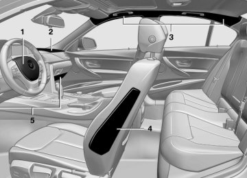
Locking separately The trunk lid can be locked separately with the switch in the front passenger glove compart‐ ment.
▷ Trunk lid secured, arrow 1. ▷ Trunk lid not secured, ar‐
row 2.
Slide the switch into the arrow 1 position. This secures the trunk lid and disconnects it from the central locking system. When the front passenger glove compartment is locked, the trunk lid cannot be opened. This is beneficial when the vehicle is parked us‐ ing valet service. The infrared remote control can be handed out without the key. Emergency unlocking
Comfort Access The concept The vehicle can be accessed without activating the remote control. All you need to do is to have the remote control with you, e.g., in your jacket pocket. The vehicle automatically detects the remote control when it is nearby or in the passenger compartment. Comfort Access supports the following func‐ tions: ▷ Unlocking/locking of the vehicle. ▷ Unlocking of the trunk lid separately. ▷ Open trunk lid with no-touch activation. ▷ Starting the engine. Functional requirements ▷ There are no external sources of interfer‐
ence nearby.
▷ To lock the vehicle, the remote control must
be located outside of the vehicle.
▷ The next unlocking and locking cycle is not
possible until after approx. 2 seconds.
▷ The engine can only be started if the remote
control is inside the vehicle.
Comparison with ordinary remote control The functions can be controlled by pressing the buttons of the remote control or Comfort Ac‐ cess.
Pull the handle inside the cargo area. The trunk lid unlocks.
38
Online Edition for Part no. 01 40 2 903 880 - 07 12 490
Opening and closing
Controls
Unlocking the trunk lid separately Press the button on the exterior of the trunk lid. button This corresponds to pressing the on the remote control.
Do not place the remote control in the cargo area
Take the remote control with you and do not leave it in the cargo area; otherwise, the remote control is locked inside the vehicle when the trunk lid is closed.◀
Open trunk lid with no-touch activation With Comfort Access, the trunk lid can be opened with no-touch activation using the re‐ mote control you are carrying. A sensor detects a directed foot motion in the center of the area at the rear of the car and the trunk lid opens. During opening, the trunk lid pivots back and up. Ensure that adequate clearance is available be‐ fore opening.
Do not touch vehicle With the foot motion, make sure there is steady stance and do not touch the vehicle; oth‐ erwise, there is a danger of injury, e. g. from hot exhaust system parts.◀ 1. Position in the center behind the vehicle. 2. Move foot in the direction of travel under‐ neath the bumper and immediately back. The hazard warning system flashes three times.
Unlocking
Grasp the door handle on the driver's or front passenger door completely, arrow 1. This cor‐ button on the re‐ responds to pressing the mote control.
Locking
Press the area on the door handle, arrow 2, with your finger for approx. 1 second. This corresponds to pressing the the remote control. To save battery power, ensure that the ignition and all electronic systems and/or power con‐ sumers are switched off before locking the ve‐ hicle.
button on
Convenient closing Press the area on the door handle, arrow 2, with the finger and hold it down. In addition to locking, the windows and the glass sunroof are closed.
Monitor the closing process Monitor the closing process to ensure that
no one becomes trapped.◀
Online Edition for Part no. 01 40 2 903 880 - 07 12 490
39
Controls
Opening and closing
The trunk lid opens, regardless of whether it was previously locked or unlocked.
Preventing inadvertent opening In situations where the trunk lid should is not to be opened with no-touch activation, en‐ sure that the remote control is located beyond the range of the sensor, at least 5 ft/1.50 m from the rear of the car. Otherwise, the trunk lid may be opened inad‐ vertently, for example by an unintentional or misinterpreted movement of the foot.◀
Malfunction Comfort Access may not function properly if it experiences interference from external sources such as mobile phones, metal objects, overhead power lines, transmission towers, etc. In this case, open or close the vehicle using the buttons on the remote control or use the integrated key in the door lock. If there is a malfunction, open the trunk lid with the remote control button or with the button on the trunk lid.
Alarm system The concept The vehicle alarm system responds to: ▷ Opening of a door, the hood or the trunk lid. ▷ Movements in the vehicle. ▷ Changes in the vehicle tilt, e.g., during at‐ tempts to steal a wheel or when towing the car.
▷ Interruptions in battery voltage. The alarm system briefly indicates tampering: ▷ By sounding an acoustic alarm. ▷ By switching on the hazard warning system. ▷ By flashing the daytime running lights.
Arming and disarming the alarm system General information When you lock or unlock the vehicle, either with the remote control or at the door lock, the alarm system is armed or disarmed at the same time. Door lock and armed alarm system The alarm system is triggered when the door is opened, if the vehicle is unlocked via the door lock. In order to terminate this alarm, unlock vehicle with the remote control or switch on the ignition, if necessary, by emergency detection of the re‐ mote control. Trunk lid and armed alarm system The trunk lid can be opened using the remote control, even if the alarm system is armed.
Press the button on the remote control for approx. 1 second.
After the trunk lid is closed, it is locked and monitored again by the alarm system. The haz‐ ard warning system flashes once. In some vehicle equipment variants, the trunk lid can only be opened using the remote control if the vehicle was unlocked first. Panic mode
Press the button on the remote control for at least 3 seconds.
Switching off the alarm ▷ Unlock the vehicle using the remote control. ▷ With Comfort Access: if you are carrying the
remote control with you, pull on the door handle.
40
Online Edition for Part no. 01 40 2 903 880 - 07 12 490
Indicator lamp on the interior rearview mirror
▷ The indicator lamp flashes briefly every
2 seconds: The system is armed.
▷ The indicator lamp flashes after locking: The doors, hood or trunk lid is not closed properly, but the rest of the vehicle is se‐ cured. After 10 seconds, the indicator lamp flashes continuously. Interior motion sensor and tilt alarm sensor are not active.
▷ The indicator lamp goes out after unlocking:
The vehicle has not been tampered with. ▷ The indicator lamp flashes after unlocking until the engine is started, but no longer than approx. 5 minutes: An alarm has been triggered.
Tilt alarm sensor The tilt of the vehicle is monitored. The alarm system responds in situations such as attempts to steal a wheel or when the car is towed. Interior motion sensor The windows and glass sunroof must be closed for the system to function properly. Avoiding unintentional alarms The tilt alarm sensor and interior motion sensor can be switched off together, such as in the fol‐ lowing situations:
Opening and closing
Controls
▷ In automatic car washes. ▷ In duplex garages. ▷ During transport on car-carrying trains, at
sea or on a trailer.
▷ When animals are to remain in the vehicle. Switching off the tilt alarm sensor and interior motion sensor
Press the remote control button again within 10 seconds as soon as the vehicle
is locked. The indicator lamp lights up for approx. 2 sec‐ onds and then continues to flash. The tilt alarm sensor and interior motion sensor are switched off until the vehicle is locked again.
Power windows General information
Take the remote control with you Take the remote control with you when
leaving the vehicle so that children, for example, cannot operate the power windows and injure themselves.◀
Opening
▷
Press the switch to the resistance
point. The window opens while the switch is held.
Online Edition for Part no. 01 40 2 903 880 - 07 12 490
41
Controls
Opening and closing
▷
Press the switch beyond the resist‐
ance point. The window opens automatically.
Pressing again stops the motion. Convenient opening, refer to page 34, via the remote control. Closing
Keep the closing path clear Monitor the closing process and make
sure that the closing path of the window is clear; otherwise, injuries may result.◀
▷
Pull the switch to the resistance point. The window closes while the switch is held.
▷
Pull the switch beyond the resistance
point. The window closes automatically. Pressing the switch stops the motion. Convenient operation, refer to page 34, via the remote control. Convenient closing, refer to page 39, with Com‐ fort Access. Pinch protection system If the closing force exceeds a specific value as a window closes, the closing action is interrupted. The window reopens slightly.
Danger of pinching even with pinch pro‐ tection
Even with the pinch protection system, check that the window's closing path is clear; other‐ wise, the closing action may not stop in certain situations, e.g., if thin objects are present.◀
No window accessories Do not install any accessories in the range
of movement of the windows; otherwise, the pinch protection system will be impaired.◀
Closing without the pinch protection system
Keep the closing path clear Monitor the closing process and make
sure that the closing path of the window is clear; otherwise, injuries may result.◀ For example, if there is an external danger or if ice on the windows prevents a window from closing normally, proceed as follows: 1. Pull the switch past the resistance point and
hold it there. Pinch protection is limited and the window reopens slightly if the closing force exceeds a certain value.
2. Pull the switch past the resistance point
again within approx. 4 seconds and hold it there. The window closes without pinch protec‐ tion.
Safety switch The safety switch in the driver's door can be used to prevent children, for example, from opening and closing the rear windows using the switches in the rear. Switching on and off Press the button. The LED lights up if the safety function
is switched on.
Safety switch for rear operation Press the safety switch when transporting children in the rear; otherwise, injury may result if the windows are closed without supervision.◀
42
Online Edition for Part no. 01 40 2 903 880 - 07 12 490
Roller sunblinds Roller sunblind for rear window General information If you are no longer able to move the roller sun‐ blind for the rear window after having activated it a number of times in a row, the system is blocked for a limited time to prevent overheat‐ ing. Let the system cool. The roller sunblind for the rear window cannot be moved at low interior temperatures. Extending or retracting roller blind for rear window
Press the button.
Roller sunblinds for the rear side windows Pull out the roller sunblind at the loop and hook it onto the bracket.
Do not open the window while the roller sunblind is raised.
Do not open the window while the roller sunblind is raised; otherwise, there is a risk of damage at high speeds that may result in personal injury.◀
Glass sunroof, powered General information The glass sunroof is operational when the igni‐ tion is switched on.
Keep the closing path clear Monitor the closing process and make
sure that the closing path of the glass sunroof is clear; otherwise, injuries may result.◀ Take the remote control with you Take the remote control with you when
leaving the vehicle so that children, for example, cannot operate the roof and injure themselves.◀
Opening and closing
Controls
Tilting the glass sunroof
Push switch upward briefly. ▷ Closed roof is tilted open. ▷ The opened roof closes until it is in its tilted position. The sliding visor stays completely open.
Opening/closing the glass sunroof and sliding visor together
▷ Slide switch back to the re‐
sistance point and hold. Glass sunroof and sliding vi‐ sor open together as long as the switch is held down.
▷ Press switch back past the resistance point. The glass sunroof and sliding visor open au‐ tomatically. Pressing the switch again stops the opening motion.
Analogously, the glass sunroof is closed by slid‐ ing the switch forward. The sliding visor remains open and can be closed by hand. Convenient operation, refer to page 34, via the remote control. Convenient closing, refer to page 39, with Com‐ fort Access. Comfort position Stops the roof in the comfort position if the roof is not fully open. This reduces wind noise in the passenger compartment.
Online Edition for Part no. 01 40 2 903 880 - 07 12 490
43
Initializing the system The system can be initialized when the vehicle is stationary and the engine is running. During the initialization, the roof closes without pinch protection.
Keep the closing path clear Monitor the closing process and make
sure that the closing path of the glass sunroof is clear; otherwise, injuries may result.◀
Press the switch up and hold it until the initialization is complete: ▷ Initialization begins within
15 seconds and is completed when the sunroof is com‐ pletely closed.
▷ The roof closes without pinch protection.
Controls
Opening and closing
If desired, continue the movement by pressing the switch. Pinch protection system If the closing force when closing the glass sun‐ roof exceeds a certain value, the closing move‐ ment is stopped, beginning at approximately the middle of the opening in the roof, or from the tilted position during closing. The glass sunroof opens again slightly.
Danger of pinching even with pinch pro‐ tection
Despite the pinch protection system, check that the roof's closing path is clear; otherwise, the closing action may not be interrupted in certain extreme situations, such as when thin objects are present.◀
Closing from the open position without pinch protection For example, if there is an external danger, pro‐ ceed as follows: 1. Press the switch forward beyond the resist‐
ance point and hold. Pinch protection is limited and the roof re‐ opens slightly if the closing force exceeds a certain value.
2. Press the switch forward again beyond the
resistance point and hold until the roof closes without pinch protection.
Closing from the raised position without pinch protection If there is an external danger, push the switch forward past the resistance point and hold it. The roof closes without pinch protection. Initializing after a power failure After a power failure during the opening or clos‐ ing process, the roof can only be operated to a limited extent.
44
Online Edition for Part no. 01 40 2 903 880 - 07 12 490
Adjusting Vehicle equipment All standard, country-specific and optional equipment that is offered in the model series is described in this chapter. Therefore, equipment is also described that is not available in a vehicle, e. g., because of the selected optional equip‐ ment or country variant. This also applies for safety-related functions and systems.
Sitting safely The ideal seating position can make a vital con‐ tribution to relaxed, fatigue-free driving. The seating position plays an important role in an accident in combination with: ▷ Safety belts, refer to page 48. ▷ Head restraints, refer to page 49. ▷ Airbags, refer to page 92.
Seats General information
Do not adjust the seat while driving Do not adjust the driver's seat while driv‐ ing, or the seat could respond with unexpected movement and the ensuing loss of vehicle con‐ trol could lead to an accident.◀
Do not incline the backrest too far to the rear
Also on the front passenger side, do not incline the backrest on the front passenger side too far to the rear during driving, or there is a risk of slipping under the safety belt in the event of an accident. This would eliminate the protection normally provided by the belt.◀
Adjusting
Controls
Manually adjustable seats At a glance
1 Forward/backward 2 Thigh support 3 Seat tilt 4 Backrest width 5 Lumbar support 6 Height 7 Backrest tilt
Forward/backward
Pull the lever and slide the seat in the desired direction. After releasing the lever, move the seat forward or back slightly to make sure it engages prop‐ erly.
Online Edition for Part no. 01 40 2 903 880 - 07 12 490
45
Controls
Adjusting
Height
Electrically adjustable seats At a glance
1 Seat and mirror memory 2 Backrest width 3 Lumbar support 4 Backrest tilt 5 Forward/backward, height, seat tilt
Note The seat setting for the driver's seat is stored for the remote control currently in use. When the vehicle is unlocked via the remote control, the position is automatically retrieved if the function, refer to page 35, is activated for this purpose. Adjustments in detail 1. Forward/back.
Pull the lever and apply your weight to the seat or lift it off, as necessary.
Backrest tilt
Pull the lever and apply your weight to the back‐ rest or lift it off, as necessary.
Seat tilt
Pull the lever and move the seat to the desired tilt. After releasing the lever, apply your weight to the seat or lift it off to make sure the seat en‐ gages properly.
46
Online Edition for Part no. 01 40 2 903 880 - 07 12 490
2. Height.
Thigh support
Adjusting
Controls
3. Seat tilt.
4. Backrest tilt.
Pull the lever at the front of the seat and adjust the thigh support.
Lumbar support The curvature of the seat backrest can be ad‐ justed in such a way that it supports the lumbar region of the spine. The lower back and the spine are supported for upright posture.
▷ Press the front/rear section of
the switch. The curvature is increased/ decreased.
▷ Press the upper/lower sec‐
tion of the switch. The curvature is shifted up/ down.
Backrest width
Change the width of the backrest using the side wings to adjust the lateral support.
Online Edition for Part no. 01 40 2 903 880 - 07 12 490
47
Controls
Adjusting
Front seat heating
Switching on
Press the button once for each temper‐ ature level.
The maximum temperature is reached when three LEDs are lit. If the drive is continued within approx. 15 mi‐ nutes, the seat heating is activated automati‐ cally with the temperature selected last. When ECO PRO, refer to page 167, is activated, the heater output is reduced.
Switching off
Press the button longer. The LEDs go out.
Rear seat heating
Switching on
Press the button once for each temper‐ ature level.
The maximum temperature is reached when three LEDs are lit.
If the drive is continued within approx. 15 mi‐ nutes, the seat heating is activated automati‐ cally with the temperature selected last. When ECO PRO, refer to page 167, is activated, the heater output is reduced.
Switching off
Press the button longer. The LEDs go out.
Safety belts Seats with safety belt The vehicle has five seats, each of which is equipped with a safety belt. Number of safety belts Your vehicle has been fitted with five safety belts for the safety of you and your passengers. How‐ ever, they can only offer protection when ad‐ justed correctly. Notes Always make sure that safety belts are being worn by all occupants before driving away. Although airbags enhance safety by providing added protection, they are not a substitute for safety belts. ▷ The shoulder strap's anchorage point will be
correct for adult seat occupants of every build if the seat is correctly adjusted.
▷ The two outer safety belt buckles,
integrated into the rear seat, are for passen‐ gers sitting on the left and right.
▷ The center rear seat belt buckle is solely in‐
tended for the center passenger.
One person per safety belt Never allow more than one person to wear a single safety belt. Never allow infants or small children to ride on a passenger's lap.◀
48
Online Edition for Part no. 01 40 2 903 880 - 07 12 490
Adjusting
Controls
above approx. 5 mph/8 km/h. It can also be ac‐ tivated if objects are placed on the front pas‐ senger seat. Damage to safety belts In the case of strain caused by accidents or damage: Have the safety belts, including the safety belt tensioners, replaced and have the belt anchors checked.
Checking and replacing safety belts Have the work performed only by your
service center; otherwise, it cannot be ensured that this safety feature will function properly.◀
Front head restraints Correctly adjusted head restraint A correctly adjusted head restraint reduces the risk of injury to cervical vertebrae in the event of an accident.
Adjusting the head restraint Correctly adjust the head restraints of all occupied seats; otherwise, there is an increased risk of injury in an accident.◀
Height Adjust the head restraint so that its center is ap‐ proximately at ear level. Distance Adjust the distance so that the head restraint is as close as possible to the back of the head. If necessary, adjust the distance by adjusting the tilt of the backrest.
Putting on the belt Lay the belt, without twisting, snugly
across the lap and shoulders, as close to the body as possible. Make sure that the belt lies low around the hips in the lap area and does not press on the abdomen. Otherwise, the belt can slip over the hips in the lap area in a frontal im‐ pact and injure the abdomen. The safety belt must not lie across the neck, rub on sharp edges, be routed over solid or breaka‐ ble objects, or be pinched.◀
Reduction of restraining effect Avoid wearing clothing that prevents the belt from fitting properly, and pull the shoulder belt periodically to readjust the tension across your lap; otherwise, the retention effect of the safety belt may be reduced.◀
Buckling the belt
Make sure you hear the latch plate engage in the belt buckle.
Unbuckling the belt 1. Hold the belt firmly. 2. Press the red button in the belt buckle. 3. Guide the belt back into its reel. Safety belt reminder for driver's seat and front passenger seat
The indicator lamp flashes or lights up and a signal sounds. Make sure that the safety belts are positioned correctly. The safety belt reminder is active at speeds
Online Edition for Part no. 01 40 2 903 880 - 07 12 490
49
Controls
Adjusting
Adjusting the height
▷ To raise: pull. ▷ To lower: press the button, arrow 1, and
push the head restraint down.
Tilt Three different tilt positions are available.
▷ Forward: pull the top edge of the head re‐
straint forward, arrow 1.
▷ Back: press the button, arrow 2. The head
restraint folds as far back as possible.
Removing Only remove the head restraint if no one will be sitting in the seat in question.
1. Pull the head restraint upward as far as pos‐
sible.
2. Press the button, arrow 1, and pull the head
restraint out completely.
Before transporting passengers Reinstall the head restraint before trans‐ porting anyone in the seat; otherwise, the pro‐ tective function of the head restraint is unavail‐ able.◀
Rear head restraints Correctly adjusted head restraint A correctly adjusted head restraint reduces the risk of injury to cervical vertebrae in the event of an accident.
Adjusting the head restraint Correctly adjust the head restraints of all occupied seats; otherwise, there is an increased risk of injury in an accident.◀
Height Adjust the head restraint so that its center is ap‐ proximately at ear level.
50
Online Edition for Part no. 01 40 2 903 880 - 07 12 490
Adjusting the height
Adjusting
Controls
▷ To raise: pull. ▷ To lower: press the button, arrow 1, and
push the head restraint down.
The center head restraint cannot be adjusted in elevation.
Folding down head restraints
Extending/retracting head restraint Only fold down head restraint if no pas‐
sengers are in the rear. Fold out retracted headr‐ ests again if passengers are being carried in the rear; otherwise, there is increased risk of injury in the event of an accident.◀
1. Pull the head restraint upward as far as pos‐
sible.
2. Press the button, arrow 1, and pull the head
restraint out completely.
Before transporting passengers Reinstall the head restraint before trans‐ porting anyone in the seat; otherwise, the pro‐ tective function of the head restraint is unavail‐ able.◀
Seat and mirror memory General information
▷ To lower flaps: press the button, arrow 1,
and press down the head restraint.
▷ Fold back up: pull up head restraints.
Removing Only remove the head restraint if no one will be sitting in the seat in question.
Two different driver's seat and exterior mirror positions can be stored and retrieved for each remote control. Settings for the backrest width and lumbar support are not stored in memory. Storing 1. Switch on the ignition. 2. Set the desired position.
Online Edition for Part no. 01 40 2 903 880 - 07 12 490
51
Controls
Adjusting
3.
Press the button. The LED in the
button lights up.
4. Press the desired button 1 or 2. The LED
goes out.
If the M button is pressed accidentally:
Press the button again. The LED goes out.
Calling up settings
Do not retrieve the memory while driving Do not retrieve the memory setting while driving, as an unexpected movement of the seat or steering wheel could result in an accident.◀
Comfort function 1. Open the driver's door. 2. Switch off the ignition. 3. Briefly press the desired button 1 or 2. The corresponding seat position is performed automatically. The procedure stops when a switch for adjust‐ ing the seat or one of the buttons is pressed. Safety mode 1. Close the driver's door or switch on the ig‐
nition.
2. Press and hold the desired button 1 or 2 until
the adjustment procedure is completed.
Calling up of a seat position deactivated After a brief period, the calling up of stored seat positions is deactivated to save battery power. To reactivate calling up of a seat position: ▷ Open and close the door or trunk lid. ▷ Press a button on the remote control. ▷ Press the Start/Stop button.
Mirrors Exterior mirrors At a glance
1 Adjusting 2 Left/right, Automatic Curb Monitor 3 Fold in and out
General information The mirror on the passenger side is more curved than the driver's side mirror.
Estimating distances correctly Objects reflected in the mirror are closer than they appear. Do not estimate the distance to the traffic behind you based on what you see in the mirror, as this will increase your risk of an accident.◀ Depending on how the vehicle is equipped, the mirror setting is stored for the remote control in use. When the vehicle is unlocked via the remote control, the position is automatically retrieved if the setting for this function is active. Selecting a mirror
To change over to the other mirror: Slide the mirror changeover switch.
Adjusting electrically
The setting corresponds to the direction in which the button is pressed.
52
Online Edition for Part no. 01 40 2 903 880 - 07 12 490
Saving positions Seat and mirror memory, refer to page 51
Adjusting manually If an electrical malfunction occurs, for example, press the edges of the mirror glass. Automatic Curb Monitor When the reverse gear is engaged, the mirror glass tilts downward slightly on the front pas‐ senger side. This improves your view of the curb and other low-lying obstacles when parking, for example.Activating
1.
Slide the mirror changeover switch
to the driver's side mirror position.
2. Engage transmission position R.
Deactivating Slide the mirror changeover switch to the pas‐ senger's side mirror position. Fold in and out
Press the button.
Possible up to approx. 15 mph/20 km/h. For example, this is advantageous ▷ In car washes. ▷ In narrow streets. ▷ For folding back mirrors that were folded
away manually.
Mirrors that were folded in are folded out auto‐ matically at a speed of approx. 25 mph/40 km/h.
Fold in the mirror in a car wash Before entering an automatic car wash, fold in the exterior mirrors by hand or with the button; otherwise, they could be damaged, de‐ pending on the width of the vehicle.◀
Adjusting
Controls
Automatic heating Both exterior mirrors are automatically heated whenever the engine is running. Automatic dimming feature Both exterior mirrors are automatically dimmed. Photocells are used for control in the Interior rear view mirror, refer to page 53. Interior rearview mirror Reducing the blinding effect
From behind when driving at night: turn the knob.
Interior rearview mirror, automatic dimming feature The concept
Photocells are used for control: ▷ In the mirror glass. ▷ On the back of the mirror.
Online Edition for Part no. 01 40 2 903 880 - 07 12 490
53
Controls
Adjusting
Functional requirement For proper operation: ▷ Keep the photocells clean. ▷ Do not cover the area between the inside
rearview mirror and the windshield.
Switching on/off
Press the button.
▷ On: the LED lights up. ▷ Off: the LED goes out.
Steering wheel General information
Do not adjust while driving Do not adjust the steering wheel while driving; otherwise, an unexpected movement could result in an accident.◀
Adjusting
1. Fold the lever down. 2. Move the steering wheel to the preferred height and angle to suit your seating posi‐ tion.
3. Fold the lever back. Steering wheel heating
54
Online Edition for Part no. 01 40 2 903 880 - 07 12 490
Transporting children safely
Controls
Transporting children safely Vehicle equipment All standard, country-specific and optional equipment that is offered in the model series is described in this chapter. Therefore, equipment is also described that is not available in a vehicle, e. g., because of the selected optional equip‐ ment or country variant. This also applies for safety-related functions and systems.
tomatic deactivation of front passenger airbags, refer to page 94.
Deactivating the front passenger airbags If a child restraint fixing system is used in the front passenger seat, the front passenger airbags must be deactivated; otherwise, there is an increased risk of injury to the child when the airbags are triggered, even with a child restraint fixing system.◀
The right place for children Note
Children in the vehicle Do not leave children unattended in the vehicle; otherwise, they could endanger them‐ selves and other persons, e.g., by opening the doors.◀
Children should always be in the rear Accident research shows that the safest place for children is in the back seat.
Transporting children in the rear Only transport children younger than
13 years of age or shorter than 5 ft/150 cm in the rear in child restraint fixing systems provided in accordance with the age, weight and size of the child; otherwise, there is an increased risk of in‐ jury in an accident. Children 13 years of age or older must wear a safety belt as soon as a suitable child restraint fixing system can no longer be used, due to their age, weight and size.◀
Children on the front passenger seat Should it ever be necessary to use a child re‐ straint fixing system in the front passenger seat, make sure that the front, knee and side airbags on the front passenger side are deactivated. Au‐
Installing child restraint fixing systems Before mounting Before mounting child restraint fixing systems, ensure that the rear seat backrests are locked. Notes
Manufacturer's information for child re‐ straint fixing systems
To select, mount and use child restraint fixing systems, observe the information provided by the system manufacturer; otherwise, the pro‐ tective effect can be impaired.◀
On the front passenger seat Deactivating airbags After installing a child restraint fixing system in the front passenger seat, make sure that the front, knee and side airbags on the front pas‐ senger side are deactivated. Deactivate the front passenger airbags auto‐ matically, refer to page 94
Deactivating the front passenger airbags If a child restraint fixing system is used in the front passenger seat, the front passenger airbags must be deactivated; otherwise, there is
Online Edition for Part no. 01 40 2 903 880 - 07 12 490
55
Controls
Transporting children safely
an increased risk of injury to the child when the airbags are triggered, even with a child restraint fixing system.◀
Seat position and height Before installing a child restraint fixing system, move the front passenger seat as far back as possible and adjust its height to the highest po‐ sition to obtain the best possible position for the belt and to offer optimal protection in the event of an accident. Do not change the seat position and height after this. Backrest width Adjustable backrest width: before installing a child restraint fixing system in the front passen‐ ger seat, open the backrest width completely. Do not change the backrest width again and do not call up a memory position.
Backrest width for the child seat Before installing a child restraint fixing
system in the front passenger seat, the backrest width must be opened completely. Do not change the adjustment after this; otherwise, the stability of the child seat will be reduced.◀
Child seat security
The rear safety belts and the front passenger safety belt can be locked against pulling out for mounting the child restraint fixing systems.
Locking the safety belt 1. Pull out the belt webbing completely. 2. Secure the child restraint fixing system with
the belt.
3. Allow the belt webbing to be pulled in and pull it taut against the child restraint fixing system. The safety belt is locked.
Unlocking the safety belt 1. Unbuckle the belt buckle. 2. Remove the child restraint fixing system. 3. Allow the belt webbing to be pulled in com‐
pletely.
LATCH child restraint fixing system LATCH: Lower Anchors and Tether for Children. Note
Manufacturer's information for LATCH child restraint fixing systems
To mount and use the LATCH child restraint fix‐ ing systems, observe the operating and safety information from the system manufacturer; oth‐ erwise, the level of protection may be reduced.◀
Mounts for the lower LATCH anchors Correctly engage the lower LATCH an‐ chors
Make sure that the lower LATCH anchors have properly engaged and that the child restraint fix‐ ing system is resting snugly against the back‐ rest; otherwise, the degree of protection offered may be reduced.◀ Before mounting the LATCH child restraint fix‐ ing system, pull the belt away from the child re‐ straint fixing system.
56
Online Edition for Part no. 01 40 2 903 880 - 07 12 490
Transporting children safely
Controls
Without a through-loading system: Position
Mounts for the lower LATCH anchors are lo‐ cated in the gap between the seat and backrest.
With a through-loading system: Position
Child restraint fixing system with a tether strap Note
LATCH mounting eyes Only use the mounting eyes for the upper LATCH retaining strap to secure child restraint fixing systems; otherwise, the mounting eyes could be damaged.◀
Mounting points
Depending on the vehicle equipment, there are two outer or three mounting points for child re‐ straint fixing systems with a tether strap.
Retaining strap guide
Retaining strap Make sure that the upper retaining strap is
not routed over the head restraints or sharp edges and is free of twisting on its way to the upper mounting point; otherwise, the belt can‐ not properly secure the child restraint fixing sys‐ tem in an accident.◀
Mounts for the lower LATCH anchors are lo‐ cated behind the indicated covers.
Mounting LATCH child restraint fixing systems 1. Mount the child restraint fixing system; refer to the operating instructions of the system. 2. Ensure that both LATCH anchors are prop‐
erly connected.
Online Edition for Part no. 01 40 2 903 880 - 07 12 490
57
Controls
Transporting children safely
Locking the doors and windows Rear doors
1 Direction of travel 2 Head restraint. 3 Hook for upper retaining strap 4 Mounting point/eye 5 Rear window shelf 6 Seat backrest 7 Upper retaining strap
Attaching the upper retaining strap to the mounting point 1. Remove the mounting point cover. 2. Raise or remove head restraints. 3. Guide the upper retaining strap between the
supports of the head restraint.
4. Attach the hook of the retaining strap to the
mounting eye.
5. Tighten the retaining strap by pulling it
down.
6. Lower and lock head restraints as needed.
Push the locking lever on the rear doors down. The door can now be opened from the outside only.
Safety switch for the rear
Press the button on the driver's door if children are being transported in the
rear. This locks various functions so that they cannot be operated from the rear: safety switch, refer to page 42.
58
Online Edition for Part no. 01 40 2 903 880 - 07 12 490
Driving Vehicle equipment All standard, country-specific and optional equipment that is offered in the model series is described in this chapter. Therefore, equipment is also described that is not available in a vehicle, e. g., because of the selected optional equip‐ ment or country variant. This also applies for safety-related functions and systems.
Start/Stop button The concept
Pressing the Start/Stop button switches the ignition on or off and starts the engine. Automatic transmission: The en‐ gine starts if the brake is de‐
pressed while pressing the Start/Stop button. Manual transmission: the engine starts if the clutch pedal is depressed when the Start/Stop button is pressed.
Ignition on Automatic transmission: Press the Start/Stop button but do not depress the brake. Manual-shift transmission: press the Start/Stop button, and do not press on the clutch pedal at the same time. All vehicle systems are ready for operation. Most of the indicator and warning lamps in the instrument cluster light up for varying lengths of time. To save battery power when the engine is off, switch off the ignition and any unnecessary electronic systems/power consumers. The ignition switches off automatically: ▷ When the vehicle is locked, if the low beams
are switched on.
Driving
Controls
▷ Shortly before the battery is discharged
completely, so that the engine can still be started.
▷ If the engine is switched off and the ignition
is switched on, the system automatically switches to the radio ready state when the door is opened if the lights are switched off or the daytime running lights are switched on. If the engine is switched off and the ignition is switched on, the system automatically switches to the radio ready state when the door is opened if the lights are switched off.
Ignition off Automatic transmission: Press the Start/Stop button again, but do not depress the brake. Manual-shift transmission: press the Start/Stop button again, and do not press on the clutch pedal at the same time. All indicator lamps in the instrument cluster go out. To save battery power when the engine is off, switch off the ignition and any unnecessary electronic systems/power consumers.
Transmission position P with the ignition off
When the ignition is switched off, position P is engaged automatically. When in an automatic car wash, for example, ensure that the ignition is not switched off accidentally.◀ Ignition automatically cuts off while the vehicle is stationary and the engine is stopped: ▷ During locking, also with the low beams ac‐
tivated.
▷ Shortly before the battery is discharged
completely, so that the engine can still be started. This function is only available when the low beams are switched off.
Online Edition for Part no. 01 40 2 903 880 - 07 12 490
59
Controls
Driving
▷ When opening and closing the driver door, if the driver's seat belt is unbuckled and the low beams are switched off.
▷ While the driver's seat belt is unbuckled, if the driver's door is open and the low beams are switched off.
When the ignition is switched off, by opening or closing the driver's door or unbuckling the driv‐ er's seat belt, the radio ready state remains ac‐ tive. Radio ready state Activate radio ready state: ▷ When the ignition is switched off: press ON/
OFF button on the radio.
▷ When the engine is running: press the Start/
Stop button.
Some electronic systems/power consumers re‐ main ready for operation. Radio ready state switches off automatically: ▷ After approx. 8 minutes. ▷ When the vehicle is locked using the central
locking system.
▷ Shortly before the battery is discharged
completely, so that the engine can still be started.
Starting the engine General information
Enclosed areas Do not let the engine run in enclosed
areas; otherwise, breathing of exhaust fumes may lead to loss of consciousness and death. The exhaust gases contain carbon monoxide, an odorless and colorless but highly toxic gas.◀
Unattended vehicle Do not leave the vehicle unattended with the engine running; doing so poses a risk of dan‐ ger.
Before leaving the vehicle with the engine run‐ ning, set the parking brake and place the trans‐ mission in position P or neutral to prevent the vehicle from moving.◀
Repeated starting in quick succession Avoid repeated unsuccessful attempts to start the vehicle or starting the vehicle several times in quick succession. Otherwise, the fuel is not burned or is inadequately burned, posing a risk of overheating and damage to the catalytic converter.◀ Do not wait for the engine to warm up while the vehicle remains stationary. Start driving at mod‐ erate engine speeds. Manual transmission Starting the engine 1. Depress the brake pedal. 2. Press on the clutch and shift to neutral. 3. Press the Start/Stop button. The ignition is activated automatically for a cer‐ tain time and is stopped as soon as the engine starts. Automatic transmission Starting the engine 1. Depress the brake pedal. 2. Press the Start/Stop button. The ignition is activated automatically for a cer‐ tain time and is stopped as soon as the engine starts.
Engine stop General information
Take the remote control with you Take the remote control with you when
leaving the vehicle so that children, for example, cannot start the engine.◀
60
Online Edition for Part no. 01 40 2 903 880 - 07 12 490
Set the parking brake and further secure the vehicle as required
Set the parking brake firmly when parking; oth‐ erwise, the vehicle could roll. On steep upward and downward inclines, further secure the vehi‐ cle, for example, by turning the steering wheel in the direction of the curb. ◀
Before driving into a car wash In order for the vehicle to be able to roll into a car wash, heed the information regarding Washing in automatic car washes, refer to page 213. Manual transmission Switching off the engine 1. With the vehicle at a standstill, press the
Start/Stop button.
2. Shift into first gear or reverse. 3. Set the parking brake. Automatic transmission Switching off the engine 1. Engage transmission position P with the ve‐
hicle stopped.
2. Press the Start/Stop button. The engine is switched off. The radio ready state is switched on.
3. Set the parking brake.
Auto Start/Stop function The concept The Auto Start/Stop function helps save fuel. The system switches off the engine during a stop, e.g., in a traffic congestion or at traffic lights. The ignition remains switched on. The engine starts again automatically for driving off. Certain vehicle components may experience additional wear as a result of this system.
Driving
Controls
Automatic mode The Auto Start/Stop function is operational after each engine start. This function is activated at speeds faster than about 3 mph, approx. 5 km/h. Engine stop The engine is switched off automatically during a stop under the following conditions: Manual transmission: ▷ Neutral is engaged and the clutch pedal is
not pressed.
▷ The driver's safety belt is buckled or the
driver's door is closed.
Automatic transmission: ▷ The selector lever is in transmission position
D.
▷ Brake pedal remains depressed while the
vehicle is stopped.
▷ The driver's safety belt is buckled or the
driver's door is closed.
The air flow of the air conditioner is reduced when the engine is switched off. Displays in the instrument cluster
The READY display in the tach‐ ometer signals that the Auto Start/Stop function is ready to start the engine automatically.
The display indicates that the conditions for an automatic en‐ gine stop have not been satisfied.
Note The engine is not switched off automatically in the following situations: ▷ External temperature below approx.
+37 ℉/+3 ℃.
Online Edition for Part no. 01 40 2 903 880 - 07 12 490
61
Controls
Driving
▷ The external temperature is high and auto‐
matic climate control is running.
▷ The passenger compartment has not yet
been heated or cooled to the required level. ▷ The engine is not yet at operating tempera‐
ture.
▷ The wheels are at a sharp angle or the steer‐
ing wheel is being turned.
▷ After driving in reverse. ▷ Fogging of the windows when the automatic
climate control is switched on.
▷ The vehicle battery charge is very low. ▷ The engine compartment lid is unlocked. ▷ The parking assistant is activated. ▷ Stop-and-go traffic. ▷ The transmission selector lever is in position
N or S/M.
Starting the engine The engine starts automatically under the fol‐ lowing conditions: ▷ Manual transmission:
The clutch pedal is pressed.
▷ Automatic transmission:
By releasing the brake pedal.