- 2015 Volvo V60 Owners Manuals
- Volvo V60 Owners Manuals
- 2016 Volvo V60 Owners Manuals
- Volvo V60 Owners Manuals
- 2014 Volvo V60 Owners Manuals
- Volvo V60 Owners Manuals
- 2012 Volvo V60 Owners Manuals
- Volvo V60 Owners Manuals
- 2013 Volvo V60 Owners Manuals
- Volvo V60 Owners Manuals
- 2011 Volvo V60 Owners Manuals
- Volvo V60 Owners Manuals
- Download PDF Manual
-
located in the centre console. If the centre console is drenched with water or other liquid, disconnect the battery cables. Do not attempt to start the car since the air- bags may deploy. Recovering the car. Volvo recommends that you have it con- veyed to an authorised Volvo workshop.
WARNING
Never drive with deployed airbags. They can make steering difficult. Other safety systems may also be damaged. The smoke and dust created when the airbags are deployed can cause skin and eye irrita- tion/injury after intensive exposure. In case of irritation, wash with cold water. The rapid deployment sequence and airbag fabric may cause friction and skin burns.
Inflatable Curtain IC (p. 35)
In the event of a side impact and/or overturning and/or some frontal colli- sionsA
Whiplash protection WHIPS (p. 36)
In a rear-end colli- sion
A The bodywork of the car could be greatly deformed in a collision without airbag deployment. A number of factors such as the rigidity and weight of the object hit, the speed of the car, the angle of the collision etc. affects how the different safety systems of the car are activated.
If the airbags (p. 30) have deployed, the fol- lowing is recommended: • Recovering the car. Volvo recommends that you have it conveyed to an author- ised Volvo workshop. Do not drive with deployed airbags.
• Volvo recommends that you engage an
authorised Volvo workshop to handle the replacement of components in the car's safety systems.
• Always contact a doctor.
NOTE
The airbags and belt tensioner system are deployed only once during a collision.
02 Safety
General information on safety mode Safety mode is a protective state that is enforced when the collision may have dam- aged any of the car's vital functions, such as the fuel lines, sensors for one of the safety systems, or the brake system.
02
Warning triangle in the analogue combined instrument panel.
}} 39
02 Safety ||
Related information • Safety mode - attempting to start the car
(p. 40)
• Safety mode - moving the car (p. 41)
Warning triangle in the digital combined instru- ment panel. If the car is involved in a collision, the text Safety mode See manual may appear in the combined instrument panel (p. 63) informa- tion display. This means that the car has reduced functionality.
WARNING
Never attempt to repair your car or reset the electronics yourself if the car has been in safety mode. This could result in per- sonal injury or the car not functioning as normal. Volvo recommends that you engage an authorised Volvo workshop to check and restore the car to normal status after Safety mode See manual has been displayed.
Safety mode - attempting to start the car If the car is set in safety mode (p. 39) then an attempt to start the car can be made if every- thing seems normal and the absence of fuel leakage has been checked.
First, check that no fuel is leaking from the car. There must be no smell of fuel either. If everything seems normal and you have checked for indications of fuel leakage, you may attempt to start the car. Remove the remote control key and open the driver's door. If a message is now shown to the effect that the ignition is on, press the start button. Then close the door and reinsert the remote control key. The car's electronics will now try to reset themselves to normal mode. Then try to start the car. If the message Safety mode See manual is still shown on the display then the car must not be driven or towed but a vehicle recovery service (p. 325) used instead. Even if the car appears to be driveable, hidden damage may make the car impossible to control once mov- ing.
02
40
WARNING
Never, under any circumstances, attempt to restart the car if it smells of fuel when the Safety mode See manual message is displayed. Leave the car at once.
WARNING
If the car is in safety mode it must not be towed. It must be transported from its location. Volvo recommends that it is transported to an authorised Volvo work- shop.
Related information • Safety mode - moving the car (p. 41)
Safety mode - moving the car If Normal mode is shown after Safety mode See manual has been reset after attempting to start the car (p. 40) , the car can be moved carefully out of a dangerous position.
Do not move the car further than necessary.
Related information • General information on safety mode
(p. 39)
02 Safety
General information on child safety Children of all ages and sizes must always sit correctly secured in the car. Never allow a child to sit on the knee of a passenger.
Volvo recommends that children travel in rear-facing child seats until as late an age as possible, at least until 3-4 years of age, and then front-facing booster cushions/child seats until up to 10 years of age. The position of a child in the car and the choice of equipment are dictated by the child's weight and size; see Child seats (p. 43).
NOTE
Regulations regarding the placement of children in cars vary from country to coun- try. Check what does apply.
Volvo has child safety equipment (child seats, booster cushions & attachment devices) which is designed for your particular car. Using Volvo's child safety equipment pro- vides you with optimum conditions for your child to travel safely in the car. Furthermore, the child safety equipment fits and is easy to use.
02
}} 41
02 Safety ||
NOTE
In the event of questions when fitting child safety products, contact the manufacturer for clearer instructions.
02
Child safety locks The rear doors and rear door windows* can be blocked manually (p. 180) or electronically (p. 181)* from opening from the inside.
Related information • Child seats - location (p. 47) • Child seat - ISOFIX (p. 51) • Child seats - upper mounting points
(p. 55)
42
* Option/accessory, for more information, see Introduction.
Child seats Children should sit comfortably and safely. Make sure that the child seat is being used correctly.
NOTE
When using child safety products it is important to read the installation instruc- tions included.
WARNING
Do not secure the straps of the child seat to the seat's horizontal adjustment bar, springs or the rails and beams under the seat. Sharp edges may damage the straps.
Look in the installation instructions for the child seat for the correct fitting.
Child seats and airbags are not compatible.
02 Safety
02
}} 43
02 Safety || Recommended child seats2
WeightFront seat (with deactivated airbag) Outer rear seat
02
Group 0
max 10 kgGroup 0+ max 13 kg
Group 0
max 10 kgGroup 0+ max 13 kg
Volvo infant seat (Volvo Infant Seat) - rear-facing child seat, secured with the ISOFIX fixture system. Type approval: E1 04301146
(L)Volvo infant seat (Volvo Infant Seat) - rear- facing child seat, secured with the car's seatbelt. Type approval: E1 04301146
(U)Volvo infant seat (Volvo Infant Seat) - rear-facing child seat, secured with the car's seatbelt. Type approval: E1 04301146
(U)Group 0
max 10 kgChild seats which are universally approved. (U)
Child seats which are universally approved. (U)
Group 0+ max 13 kg
Group 1
9-18 kgVolvo rear-facing/turnable child seat (Volvo Convertible Child Seat) - rear-facing child seat, secured with the car's seatbelt and straps. Type approval: E5 04192
(L)Volvo rear-facing/turnable child seat (Volvo Convertible Child Seat) - rear-facing child seat, secured with the car's seatbelt and straps. Type approval: E5 04192
(L)Centre rear seat
Volvo infant seat (Volvo Infant Seat) - rear-facing child seat, secured with the car's seatbelt. Type approval: E1 04301146
(U)Child seats which are univer- sally approved. (U)
2 With regard to other child seats your car should be included in the manufacturer's enclosed list of vehicles or be universally approved in accordance with the ECE R44 legal requirement.
44
Weight
Front seat (with deactivated airbag) Outer rear seat
Group 1
9-18 kgChild seats which are universally approved. (U)
Child seats which are universally approved. (U)
Group 2
15-25 kgGroup 2
15-25 kgVolvo rear-facing/turnable child seat (Volvo Convertible Child Seat) - rear-facing child seat, secured with the car's seatbelt and straps. Type approval: E5 04192
(L)Volvo rear-facing/turnable child seat (Volvo Convertible Child Seat) - rear-facing child seat, secured with the car's seatbelt and straps. Type approval: E5 04192
(L)Volvo rear-facing/turnable child seat (Volvo Convertible Child Seat) - front-facing child seat, secured with the car's seatbelt. Type approval: E5 04191
(U)Volvo rear-facing/turnable child seat (Volvo Convertible Child Seat) - front-facing child seat, secured with the car's seatbelt. Type approval: E5 04191
(U)Group 2/3
15-36 kgVolvo booster seat with backrest (Volvo Booster Seat with backrest). Type approval: E1 04301169
(UF)Volvo booster seat with backrest (Volvo Booster Seat with backrest). Type approval: E1 04301169
(UF)Group 2/3
15-36 kgBooster cushion with and without backrest (Booster Cushion with and without backrest). Type approval: E5 04216
(UF)Booster cushion with and without backrest (Booster Cushion with and without backrest). Type approval: E5 04216
(UF)02 Safety
Centre rear seat
Child seats which are univer- sally approved. (U)
02
Volvo rear-facing/turnable child seat (Volvo Convertible Child Seat) - front-facing child seat, secured with the car's seatbelt. Type approval: E5 04191
(U)Volvo booster seat with back- rest (Volvo Booster Seat with backrest). Type approval: E1 04301169
(UF)Booster cushion with and with- out backrest (Booster Cushion with and without backrest). Type approval: E5 04216
(UF)}} 45
02 Safety || Weight
Front seat (with deactivated airbag) Outer rear seat
Group 2/3
15-36 kg02
Integrated booster cushion (Integrated Booster Cushion) - available as a factory fitted option. Type approval: E5 04189
(B)Centre rear seat
L: Suitable for specific child seats. These child seats may be intended for use in a special car model, limited or semi-universal categories. U: Suitable for universally approved child seats in this weight class. UF: Suitable for front-facing universally approved child seats in this weight class. B: Built-in child seats approved for this weight class.
Related information • Child seats - location (p. 47) • Child seats - upper mounting points
(p. 55)
• Child seat - ISOFIX (p. 51) • General information on child safety (p. 41)
46
Child seats - location Always fit child seats/booster cushions (p. 43) in the rear seat if the passenger airbag is acti- vated (p. 32). If a child is sitting on the front passenger seat then he/she could suffer seri- ous injury if the airbag deploys.
The warning label for the passenger airbag is fitted in one of the following two locations in the car:
Alternative 1: Position of airbag label on passen- ger side sun visor.
Alternative 2: Position of airbag label on passen- ger side door pillar. The label becomes visible when the passenger door is opened. You may place: • a child seat/booster cushion on the front passenger seat provided there is no acti- vated airbag on the front passenger side. • one or more child seats/booster cushions
in the rear seat. WARNING
Never use a rear-facing child seat on a seat protected by an activated airbag. Fail- ure to follow this advice can lead to death or serious injury to the child.
02 Safety
WARNING
Never place a child in a child seat or on a booster cushion in the front seat if the air- bag is activated. Never allow anybody to stand or sit in front of the front passenger seat. No one shorter than 140 cm should ever sit in the front passenger seat if the airbag is activated. Failure to follow the advice given above can endanger life.
WARNING
Booster cushions/child seats with steel braces or some other design that could rest on the seatbelt buckle's opening but- ton must not be used, as they could cause the seatbelt buckle to open accidentally. Do not allow the upper section of the child seat to rest against the windscreen.
Related information • General information on child safety (p. 41) • Child seats - upper mounting points
(p. 55)
• Child seat - ISOFIX (p. 51)
02
47
02 Safety
02
Child seat - two-stage booster seat* The integrated booster seats in the rear seat allow children to sit comfortably and safely.
The booster cushions are specially designed to provide optimum safety. In combination with the seatbelt (p. 25) they are approved for children who weigh between 15 and 36 kg and who are at least 95 cm in height.
Correct position, the seatbelt should be posi- tioned in on the shoulder.
WARNING
Volvo recommends that repair or replace- ment is only carried out by an authorised Volvo workshop. Do not make any modifi- cations or additions to the booster cush- ion. If an integrated booster cushion has been subjected to a major load, such as in conjunction with a collision, the entire booster cushion must be replaced. Even if the booster cushion appears to be undam- aged, it may not afford the same level of protection. The booster cushion must also be replaced if it is heavily worn.
WARNING
If the instructions for the two-stage booster seat are not followed then the child could sustain serious injury in the event of an accident.
Incorrect position, the head restraint must be adjusted as high as the head and the seatbelt must not be below the shoulder. Check before driving that: • the integrated two-stage booster seat is correctly set in accordance with the table (p. 49) and in locked position
• the seatbelt is in contact with the child's
body and is not slack or twisted
• the seatbelt does not lie across the
child's throat or below the shoulder (see preceding illustrations)
• the lap section of the seatbelt is posi-
tioned low over the pelvis to provide opti- mal protection.
Adjusting the booster seat's two levels is per- formed by raising (p. 49) and lowering (p. 50).
48
* Option/accessory, for more information, see Introduction.
Two-stage booster seat* - raising The integrated booster seat (p. 48) in the rear seat can be folded up into two stages. How many stages the cushion should be folded up depends on the child's weight.
Stage 1
22-36 kg
Stage 2
15-25 kg
Weight
Stage 13
Pull the handle forward and up in order to release the booster cushion.
3 Lower stage. 4 Upper stage.
02 Safety
Stage 24
Press the booster cushion backwards to lock.
Start from the lower stage. Press the but- ton.
* Option/accessory, for more information, see Introduction.
02
}} 49
02 Safety ||
02
Two-stage booster seat* - lowering The integrated booster seat (p. 48) in the rear seat can be folded down from the upper or lower stage to fully lowered position in the seat cushion. However, it is not possible to adjust the booster cushion from the upper stage to the lower stage.
Lift the booster cushion up at the front edge and press it back against the back- rest to lock.
NOTE
It is not possible to adjust the booster seat from stage 2 to stage 1. It must first be reset by being fully folded down (p. 50) into the seat cushion.
Related information • Two-stage booster seat* - lowering
(p. 50)
Press down with your hand in the centre of the cushion in order to lock it.
IMPORTANT
Check that there are no loose objects (e.g. toys) left behind in the space under the cushion before lowering.
Pull the handle forwards to release the cushion.
NOTE
When folding the rear backrest the booster seat must first be lowered.
Related information • Two-stage booster seat* - raising (p. 49)
50
* Option/accessory, for more information, see Introduction.
Child seat - ISOFIX ISOFIX is a fixture system for car child seats (p. 43) that is based on an international stand- ard.
• General information on child safety (p. 41)
Mounting points for the ISOFIX fixture system are concealed behind the lower section of the rear seat backrest, in the outer seats. The location of the mounting points is indi- cated by symbols in the backrest upholstery (see preceding illustration). Press the seat cushion down to access the mounting points. Always follow the manufacturer's installation instructions when connecting a child seat to the ISOFIX mounting points.
Related information • ISOFIX - size classes (p. 51) • ISOFIX - types of child seat (p. 53)
02 Safety
ISOFIX - size classes There is a size classification for child seats using the ISOFIX (p. 51) fixture system in order to assist users in choosing the correct type of child seat (p. 53).
02
Size class
Description
B1
Full size, front-facing child seat
Reduced size (alt. 1), front- facing child seat
Reduced size (alt.2), front-fac- ing child seat
Full size, rear-facing child seat
Reduced size, rear-facing child seat
Rear-facing infant seat
Transverse infant seat, left- hand
Transverse infant seat, right- hand
}} 51
02 Safety ||
WARNING
Never place the child in the passenger seat if the car is fitted with an activated air- bag.
02
NOTE
If an ISOFIX child seat has no size classifi- cation, the car model must be included on the vehicle list for the child seat.
NOTE
Volvo recommends that you contact an authorised Volvo dealer for recommenda- tions about which ISOFIX child seats Volvo recommends.
52
ISOFIX - types of child seat Child seats are in different sizes – cars are in different sizes. This means that not all child
seats are suitable for all seats in all car mod- els.
Type of child seat
Weight
Size class
Passenger seats for ISOFIX installation of child seats
02
Front seat
Outer rear seat
02 Safety
Infant seat transverse
max 10 kg
Infant seat, rear-facing
max 10 kg
Infant seat, rear-facing
max 13 kg
Child seat, rear-facing
9-18 kg
OK (IL)
OK (IL)
OK (IL)
OK (IL)
OK (IL)
OK (IL)
}} 53
02 Safety || Type of child seat
Weight
Size class
Passenger seats for ISOFIX installation of child seats
Front seat
Outer rear seat
02
Front-facing child seat
9-18 kg
B1
OKA (IUF)
OKA (IUF)
OKA (IUF)
X: The ISOFIX position is not suitable for ISOFIX child seats in this weight class and/or size class. IL: Suitable for specific ISOFIX child seats. These child seats may be intended for use in a special car model, limited or semi-universal catego- ries. IUF: Suitable for front-facing ISOFIX child seats that are universally approved in this weight class.
A Volvo recommends rear-facing child seats for this group.
Make sure you select the right size class (p. 51) of child seat with ISOFIX (p. 51) fixture system.
54
Child seats - upper mounting points The car is equipped with upper mounting points for certain front-facing child seats (p. 43). These mounting points are located on the rear of the seat.
NOTE
In cars with a cargo cover over the lug- gage compartment, this must be removed before child seats can be attached to the securing points.
For detailed information on how the child seat should be tensioned in the upper mounting points, see the seat manufacturer's instruc- tions.
WARNING
The child seat's straps must always be drawn through the hole in the head restraint leg before they are tensioned at the attachment point.
The upper mounting points are primarily intended for use with front-facing child seats. Volvo recommends that small children should sit in rear-facing child seats to as late an age as possible.
Related information • General information on child safety (p. 41) • Child seats - location (p. 47) • Child seat - ISOFIX (p. 51)
NOTE
Fold the head restraints in order to facili- tate fitting this type of child seat in cars with folding head restraints on the outer seats.
02 Safety
02
55
INSTRUMENTS AND CONTROLS
Instruments and controls, left-hand drive car - overview The overview shows where the car's displays and controls are located.
03 Instruments and controls
03
}} 57
03 Instruments and controls || Overview, left-hand drive cars
03
58
03 Instruments and controls
Function
See
Seat adjustment*
(p. 81).
Headlamp control, opener for fuel filler flap and tailgate
(p. 86), (p. 309) and (p. 178).
Related information • Outside temperature gauge (p. 72) • Trip meter (p. 72) • Clock (p. 73)
03
Function
Menus and mes- sages, direction indicators, main/ dipped beam, trip computer
Manual gear chang- ing in an automatic gearbox*
Cruise control*
Horn, airbags
Combined instru- ment panel
Menu navigation, audio control, phone control*
START/STOP ENGINE button
See
(p. 107), (p. 110), (p. 95), (p. 89) and (p. 121).
(p. 281).
(p. 198) and (p. 201).
(p. 84) and (p. 30).
(p. 63).
(p. 110) and the Sensus Infotainment supplement.
(p. 272).
Ignition switch
(p. 78).
Screen for infotain- ment system and display of menus
(p. 110) and the Sensus Infotainment supplement.
Function
Door handle
Control panel
Hazard warning flashers
See
–
(p. 176), (p. 181), (p. 100) and (p. 102).
(p. 94).
Control panel for infotainment system and menu naviga- tion
(p. 110) and the Sensus Infotainment supplement.
Control panel for cli- mate control
(p. 130).
Gear selector
Controls for active chassis (Four-C)*
(p. 280), (p. 281) or (p. 285).
(p. 187).
Wipers and washing
(p. 98).
Steering wheel adjustment
Bonnet opener
Parking brake
(p. 84).
(p. 365).
(p. 302).
* Option/accessory, for more information, see Introduction.
59
03 Instruments and controls
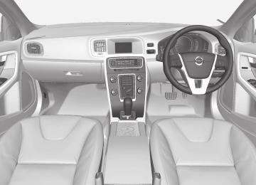
Instruments and controls, right-hand drive car - overview The overview shows where the car's displays and controls are located.
03
60
Overview, right-hand drive cars
03 Instruments and controls
03
}} 61
Function
See
Control panel for infotainment system and menu naviga- tion
(p. 110) and the Sensus Infotainment supplement.
Hazard warning flashers
(p. 94).
Bonnet opener
(p. 365).
Related information • Outside temperature gauge (p. 72) • Trip meter (p. 72) • Clock (p. 73)
03 Instruments and controls ||
Function
See
03
Screen for infotain- ment system and display of menus
Ignition switch
START/STOP ENGINE button
Manual gear chang- ing in an automatic gearbox*
Cruise control*
Combined instru- ment panel
Horn, airbags
Menu navigation, audio control, phone control*
(p. 110) and the Sensus Infotainment supplement.
(p. 78).
(p. 272).
(p. 281).
(p. 198) and (p. 201).
(p. 63).
(p. 84) and (p. 30).
(p. 110) and the Sensus Infotainment supplement.
Wipers and washing
(p. 98).
Door handle
–
Function
Control panel
Headlamp control, opener for fuel filler flap and tailgate
See
(p. 176), (p. 181), (p. 100) and (p. 102).
(p. 86), (p. 309) and (p. 178).
Seat adjustment*
(p. 81).
Parking brake
Steering wheel adjustment
Menus and mes- sages, direction indicators, main/ dipped beam, trip computer
Gear selector
Controls for active chassis (Four-C)*
(p. 302).
(p. 84).
(p. 107), (p. 110), (p. 95), (p. 89) and (p. 121).
(p. 280), (p. 281) or (p. 285).
(p. 187).
Control panel for cli- mate control
(p. 130).
62
* Option/accessory, for more information, see Introduction.
Combined instrument panel The combined instrument panel's information display shows information on some of the car's functions, as well as messages. • Analogue combined instrument panel -
overview (p. 63)
• Digital combined instrument panel - over-
view (p. 64)
• Combined instrument panel - meaning of
indicator symbols (p. 68)
• Combined instrument cluster - meaning
of warning symbols (p. 70)
03 Instruments and controls
Analogue combined instrument panel - overview The combined instrument panel's information display shows information on some of the car's functions, as well as messages.
Information display
Gauges and indicators
Fuel gauge. When the indicator lowers to only one white marking1, the yellow indi- cator symbol for low level in the fuel tank is illuminated. See also Trip computer - supplementary information (p. 121) and Filling up with fuel (p. 309). Eco meter The meter provides an indica- tion of how economically the car is being driven. The higher the reading on the scale, the more economical it is. Speedometer
Information display, analogue instrument panel. The combined instrument panel's information display shows information on some of the car's functions, e.g. cruise control and trip computer, as well as messages. The informa- tion is shown with symbols and text. There are further descriptions under the functions that use the display.
1 When the display's message "Distance to empty fuel tank:" starts to show "----", the marking becomes red.
03
}} 63
03 Instruments and controls ||
Tachometer. The meter indicates engine speed in thousands of revolutions per minute (rpm). Gear shift indicator2/Gear position indica- tor3 See also Gear shift indicator* (p. 280), Automatic gearbox -- Geartronic* (p. 281) or Automatic gear- box -- Powershift* (p. 285).
03
Indicator and warning symbols
Indicator and warning symbols, analogue instru- ment panel.
Indicator symbols
Indicator and warning symbols
Warning symbols4
Functionality check All indicator and warning symbols, apart from symbols in the centre of the information dis- play, illuminate in key position II or when the engine is started. When the engine has started, all the symbols should go out except the parking brake symbol, which only goes out when the brake is disengaged. If the engine does not start or if the function- ality check is carried out in key position II then all symbols go out within a few seconds except the symbol for faults in the car's emis- sions system and the symbol for low oil pres- sure.
Related information • Combined instrument panel (p. 63) • Combined instrument panel - meaning of
indicator symbols (p. 68)
• Combined instrument cluster - meaning
of warning symbols (p. 70)
Digital combined instrument panel - overview The combined instrument panel's information display shows information on some of the car's functions, as well as messages.
Information display
Information display, digital instrument panel*. The combined instrument panel's information display shows information on some of the car's functions, e.g. cruise control and trip computer, as well as messages. The informa- tion is shown with symbols and text. There are further descriptions under the functions that use the display.
2 Manual gearbox. 3 Automatic gearbox. 4 Certain engine variants do not have systems to warn of oil pressure loss. In cars with these variants the symbol for low oil pressure is not used. Warning for low oil level is via display text. For
more information, see Engine oil - general (p. 367).
64
* Option/accessory, for more information, see Introduction.
Gauges and indicators Alternative themes can be selected for the digital combined instrument panel. Possible themes are "Elegance", "Eco" and "Performance". A theme can only be selected when the engine is running. To select the theme, press the left-hand stalk switch's OK button and select the Themes menu option by turning the thumbwheel on the lever. Press the OK button. Turn the thumbwheel to select the theme and confirm the selection by pressing the OK button. On certain model variants, the appearance of the centre console's screen follows the theme selected for the combined instrument panel. The contrast mode and colour mode for the instrument can also be set using the left-hand stalk switch. For more information on menu navigation, see Menu navigation - combined instrument panel (p. 107). The choice of theme and setting of contrast mode and colour mode can be stored for each remote control key in the car key mem- ory*, see Remote control key - personalisa- tion* (p. 160).
03 Instruments and controls
Geartronic* (p. 281) or Automatic gear- box -- Powershift* (p. 285).
Gauges and indicators, theme "Elegance".
Fuel gauge. When the indicator lowers to only one white marking5, the yellow indi- cator symbol for low level in the fuel tank is illuminated. See also Trip computer - supplementary information (p. 121) and Filling up with fuel (p. 309). Temperature gauge for engine coolant
Speedometer
Tachometer. The meter indicates engine speed in thousands of revolutions per minute (rpm). Gear shift indicator6/Gear position indica- tor7 See also Gear shift indicator* (p. 280), Automatic gearbox --
Gauges and indicators, theme "Eco".
Fuel gauge. When the indicator lowers to only one white marking5, the yellow indi- cator symbol for low level in the fuel tank is illuminated. See also Trip computer - supplementary information (p. 121) and Filling up with fuel (p. 309). Eco guide. See also Eco guide & Power guide* (p. 67). Speedometer
5 When the display's message "Distance to empty fuel tank:" starts to show "----", the marking becomes red. 6 Manual gearbox. 7 Automatic gearbox.
* Option/accessory, for more information, see Introduction.
03
}} 65
03 Instruments and controls ||
Tachometer. The meter indicates engine speed in thousands of revolutions per minute (rpm). Gear shift indicator6/Gear position indica- tor7. See also Gear shift indicator* (p. 280), Automatic gearbox -- Geartronic* (p. 281) or Automatic gear- box -- Powershift* (p. 285).
03
Speedometer
Indicator and warning symbols
Tachometer. The meter indicates engine speed in thousands of revolutions per minute (rpm). Power guide. See also Eco guide & Power guide* (p. 67). Gear shift indicator6/Gear position indica- tor7. See also Gear shift indicator* (p. 280), Automatic gearbox -- Geartronic* (p. 281) or Automatic gear- box -- Powershift* (p. 285).
Indicator and warning symbols, digital instrument panel.
Indicator symbols
Indicator and warning symbols
Warning symbols8
Gauges and indicators, theme "Performance".
Fuel gauge. When the indicator lowers to only one white marking5, the yellow indi- cator symbol for low level in the fuel tank is illuminated. See also Trip computer - supplementary information (p. 121) and Filling up with fuel (p. 309). Temperature gauge for engine coolant
6 Manual gearbox. 7 Automatic gearbox. 5 When the display's message "Distance to empty fuel tank:" starts to show "----", the marking becomes red. 8 Certain engine variants do not have systems to warn of oil pressure loss. In cars with these variants the symbol for low oil pressure is not used. Warning for low oil level is via display text. For
more information, see Engine oil - general (p. 367).
66
* Option/accessory, for more information, see Introduction.
03 Instruments and controls
Functionality check All indicator and warning symbols, apart from symbols in the centre of the information dis- play, illuminate in key position II or when the engine is started. When the engine has started, all the symbols should go out except the parking brake symbol, which only goes out when the brake is disengaged. If the engine does not start or if the function- ality check is carried out in key position II then all symbols go out within a few seconds except the symbol for faults in the car's emis- sions system and the symbol for low oil pres- sure.
Related information • Combined instrument panel (p. 63) • Combined instrument panel - meaning of
indicator symbols (p. 68)
• Combined instrument cluster - meaning
of warning symbols (p. 70)
Eco guide & Power guide* Eco guide and Power guide are two com- bined instrument panel (p. 63) instruments which help the driver to drive the car with optimum driving economy. The car also stores statistics of journeys made, which can be viewed in the form of a block diagram; see Trip computer - trip statis- tics* (p. 122).
Eco guide This instrument provides an indication of how economically the car is being driven. To view this function, select the theme "Eco"; see Digital combined instrument panel - over- view (p. 64).
Instantaneous value The instantaneous value is shown here - the higher the reading on the scale, the better. The instantaneous value is calculated based on speed, engine speed, engine power uti- lised plus use of the foot brake. Optimum speed (50-80 km/h) and low engine speeds are encouraged. The pointers fall dur- ing acceleration and braking. Very low instantaneous values illuminate the red zone on the meter (with a short delay), which means poor driving economy and hence should be avoided. Average value The average value slowly follows the instanta- neous value and describes how the car has been driven most recently. The higher the pointers on the scale, the better the economy achieved by the driver.
Power guide This instrument shows the relationship between how much power (Power) is being taken from the engine and how much power is available. To view this function, select the theme "Performance"; see Digital combined instru- ment panel - overview (p. 64).
Instantaneous value
Average value
* Option/accessory, for more information, see Introduction.
03
}} 67
03 Instruments and controls ||
Combined instrument panel - meaning of indicator symbols The indicator symbols alert the driver that a function is activated, that the system is oper- ating, or that an error or failure has occurred.
03
Available engine power
Engine power utilised
Available engine power The smaller, upper pointer shows the availa- ble engine power9. The higher the reading on the scale, the more power is available in the current gear. Engine power utilised The larger, lower pointer shows the engine power utilised9. The higher the reading on the scale, the more power is being taken from the engine. A large gap between the two pointers indi- cates a large power reserve.
Indicator symbols Symbol Specification
ABL fault
Emissions system
ABS fault
Rear fog lamp on
Stability system, see Electronic stability control (ESC) - general (p. 187)
Stability system, sport mode, see Electronic stability control (ESC) - operation (p. 188)
Engine preheater (diesel)
Low level in fuel tank
9 Power is dependent on engine speed.
68
* Option/accessory, for more information, see Introduction.
Symbol Specification
Information, read display text
Main beam On
Left-hand direction indicator
Right-hand direction indicator
Eco- function on, see ECO* (p. 298)
Start/Stop, the engine auto- stopped; see Start/Stop* - function and operation (p. 289)
Tyre pressure system , see Tyre pressure monitoring* (p. 339)
ABL fault The symbol illuminates if a fault has arisen in the ABL function (Active Bending Lights). Emissions system If the symbol illuminates after the engine has been started then it may be due to a fault in the car's emissions system. Drive to a work- shop for checking. Volvo recommends that you seek assistance from an authorised Volvo workshop.
03 Instruments and controls
Left/right-hand direction indicator Both direction indicator symbols flash when the hazard warning flashers are used. Eco function on This symbol illuminates when the Eco func- tion is activated. Start/Stop The symbol shines when the engine is auto- stopped. Tyre pressure system The symbol illuminates in the event of low tyre pressure, or if a fault arises in the tyre pressure system.
ABS fault If this symbol illuminates then the system is not working. The car's regular brake system continues to work, but without the ABS func- tion. 1. Stop the car in a safe place and turn off
the engine.
2. Restart the engine. 3.
If the symbol remains illuminated, drive to a workshop to have the ABS system checked. Volvo recommends that you seek assistance from an authorised Volvo workshop.
Rear fog lamp on This symbol illuminates when the rear fog lamp is switched on. Stability system A flashing symbol indicates that the stability system is operating. If the symbol illuminates with constant glow then there is a fault in the system. Stability system, sport mode Sport mode allows for a more active driving experience. The system then detects whether the accelerator pedal, steering wheel move- ments and cornering are more active than in normal driving and then allows controlled skidding of the rear section up to a certain level before it intervenes and stabilises the
car. The symbol illuminates when the sport mode is activated. Engine preheater (diesel) This symbol illuminates during engine pre- heating. Preheating takes place mostly due to low temperature. Low level in fuel tank When the symbol illuminates the level in the fuel tank is low, refuel as soon as possible. Information, read display text When one of the car's systems does not behave as intended, this information symbol illuminates and a text appears on the informa- tion display. The message text is cleared with the OK button, see Menu navigation - com- bined instrument panel (p. 107), or it disap- pears automatically after a time (time depending on which function is indicated). The information symbol can also illuminate in conjunction with other symbols.
NOTE
When a service message is shown, the symbol and message are cleared using the OK button, or disappear automatically after a time.
Main beam On The symbol illuminates when main beam is on and with main beam flash.
03
}} 69
03 Instruments and controls || Reminder – doors not closed If one of the doors is not closed properly then the information or warning symbol illuminates together with an explanatory image in the information display. Stop the car in a safe place as soon as possible and close the door that is open.
03
If the car is driven at a speed lower than approx. 7 km/h then the informa-
tion symbol illuminates.
If the car is driven at a speed higher than approx. 7 km/h then the warning
symbol illuminates. If the bonnet10 is not closed properly then the warning symbol illuminates together with an explanatory image in the information display. Stop the car in a safe place as soon as possi- ble and close the bonnet. If the tailgate is not closed properly then the information symbol illuminates together with an explanatory image in the information dis- play. Stop the car in a safe place as soon as possible and close the tailgate.
Related information • Combined instrument panel (p. 63) • Combined instrument cluster - meaning
of warning symbols (p. 70)
• Digital combined instrument panel - over-
view (p. 64)
10 Only cars with alarm*.
70
* Option/accessory, for more information, see Introduction.
Combined instrument cluster - meaning of warning symbols The warning symbols alert the driver that an important function is activated, or that a seri- ous error or a serious failure has occurred.
Warning symbols Symbol Specification
Low oil pressureA
Parking brake applied, digital instrument panel
Parking brake applied, ana- logue instrument panel
Airbags – SRS
Seatbelt reminder
Alternator not charging
Fault in brake system
Warning
A Certain engine variants do not have systems to warn of oil
pressure loss. In cars with these variants the symbol for low oil pressure is not used. Warning for low oil level is via display text. For more information, see Engine oil - general (p. 367).
Low oil pressure If this symbol illuminates during driving then the engine's oil pressure is too low. Stop the engine immediately and check the engine oil level, top up if necessary. If the symbol illumi- nates and the oil level is normal, contact a workshop. Volvo recommends that you seek assistance from an authorised Volvo work- shop. Parking brake applied This symbol illuminates with a constant glow when the parking brake is applied. The sym- bol flashes during application, and then changes over to a constant glow. A flashing symbol in any other situation means that a fault has arisen. Read the mes- sage on the information display. For more information, see Parking brake (p. 302). Airbags – SRS If this symbol remains illuminated or illumi- nates while driving, it means a fault has been detected in the seatbelt buckle, SRS, SIPS, or IC systems. Drive immediately to a workshop to have the system checked. Volvo recom- mends that you seek assistance from an authorised Volvo workshop. Seatbelt reminder This symbol flashes if someone in a front seat has not put on their seatbelt or if someone in a rear seat has taken off their seatbelt.
Alternator not charging This symbol illuminates during driving if a fault has occurred in the electrical system. Visit a workshop. Volvo recommends that you seek assistance from an authorised Volvo workshop. Fault in brake system If this symbol illuminates, the brake fluid level may be too low. Stop the car in a safe place and check the level in the brake fluid reser- voir; see Brake and clutch fluid - level (p. 373). If the brake and ABS symbols illuminate at the same time, there may be a fault in the brake force distribution system. 1. Stop the car in a safe place and turn off
the engine.
2. Restart the engine.
• If both symbols extinguish, continue
driving.
• If the symbols remain illuminated,
check the level in the brake fluid reser- voir; see Brake and clutch fluid - level (p. 373). If the brake fluid level is nor- mal but the symbols are still illumi- nated, the car can be driven, with great care, to a workshop to have the brake system checked. Volvo recommends that you seek assistance from an authorised Volvo workshop.
11 Only cars with alarm*.
03 Instruments and controls
WARNING
If the brake fluid is under the MIN level in the brake fluid reservoir, do not drive fur- ther before topping up the brake fluid. The loss of brake fluid must be investiga- ted by a workshop. Volvo recommends that you contact an authorised Volvo workshop.
WARNING
If the BRAKE and ABS symbols are lit at the same time, there is a risk that the rear end will skid during heavy braking.
Warning The red warning symbol illuminates when a fault has been indicated which could affect the safety and/or driveability of the car. An explanatory text is shown on the information display at the same time. The symbol remains visible until the fault has been rectified but the text message can be cleared with the OK button; see Menu navigation - combined instrument panel (p. 107). The warning sym- bol can also illuminate in conjunction with other symbols. Action: 1. Stop in a safe place. Do not drive the car
further.
2. Read the information on the information display. Implement the action in accord- ance with the message in the display. Clear the message using the OK button.
Reminder – doors not closed If one of the doors is not closed properly then the information or warning symbol illuminates together with an explanatory image in the information display. Stop the car in a safe place as soon as possible and close the door that is open.
If the car is driven at a speed lower than approx. 7 km/h then the informa-
tion symbol illuminates.
If the car is driven at a speed higher than approx. 7 km/h then the warning
symbol illuminates. If the bonnet11 is not closed properly then the warning symbol illuminates together with an explanatory image in the information display. Stop the car in a safe place as soon as possi- ble and close the bonnet. If the tailgate is not closed properly then the information symbol illuminates together with an explanatory image in the information dis- play. Stop the car in a safe place as soon as possible and close the tailgate.
* Option/accessory, for more information, see Introduction.
03
}} 71
03 Instruments and controls || Related information • Combined instrument panel (p. 63) • Combined instrument panel - meaning of
indicator symbols (p. 68)
Outside temperature gauge The display for the outside temperature gauge appears in the combined instrument panel.
Trip meter The trip meter display appears in the com- bined instrument panel.
• Digital combined instrument panel - over-
view (p. 64)
Display for outside temperature gauge, digital instrument panel Display for outside temperature gauge, analogue instrument panel
When the temperature lies between +2 °C to -5 °C a snowflake symbol illuminates in the display. This warns of icy roads. If the car has been stationary, the gauge may display a reading that is too high.
Related information • Combined instrument panel (p. 63)
Trip meter, digital instrument. Display for trip meter12
The two trip meters T1 and T2 are used for measuring short distances. The distance is shown in the display. Turn the left stalk switch thumbwheel to show the required meter. A long press (until the change occurs) on the left-hand stalk switch's RESET button resets the trip meter shown. For more information, see Trip computer - supplementary informa- tion (p. 121).
Related information • Combined instrument panel (p. 63)
12 Display appearance may differ depending on instrument variant.
03
72
Clock The clock display appears in the combined instrument panel.
Clock, digital instrument panel.
Display for showing the time13
Set the clock The clock can be adjusted in the menu sys- tem MY CAR, see MY CAR (p. 110).
Related information • Combined instrument panel (p. 63)
03 Instruments and controls
Combined instrument panel - licenses A license is an agreement for the right to operate a certain activity or the right to use someone else's entitlement according to the terms and conditions in the agreement. The following text is Volvo's agreement with the manufacturer/developer.
Combined Instrument Panel Software Open Source Software Notice This product uses certain free / open source and other software originating from third parties, that is subject to the GNU Lesser General Public License version 2 (LGPLv2), The FreeType Project License ("FreeType License") and other different and/or additional copy right licenses, disclaimers and notices. The links to access the exact terms of LGPLv2, and the other open source software licenses, disclaimers, acknowledgements and notices are provided to you below. Please refer to the exact terms of the relevant License, regarding your rights under said licenses. Volvo Car Corporation (VCC) offers to provide the source code of said free/open source software to you for a charge covering the cost of performing such distribution, such as the cost of media, shipping and handling, upon written request. Please contact your nearest Volvo Dealer.
The offer is valid for a period of at least three (3) years from the date of the distribution of this product by VCC / or for as long as VCC offers spare parts or customer support. Portions of this product uses software copyrighted © 2007 The FreeType Project (www.freetype.org). All rights reserved. Portions of this product uses software with Copyright © 1994–2013 Lua.org, PUC-Rio (http://www.lua.org/)
03
This product includes software under following licenses: LGPL v2.1: http://www.gnu.org/licenses/old- licenses/lgpl-2.1.html • GNU FriBidi • DevIL The FreeType Project License: http:// git.savannah.gnu.org/cgit/freetype/ freetype2.git/tree/docs/FTL.TXT • FreeType 2
13 The time is shown in the centre of an analogue instrument panel.
}} 73
03 Instruments and controls
MIT License: http: http://opensource.org/ licenses/mit-license.html • Lua
03
Symbols in the display There are a variety of different symbols in the display in the car. The symbols are divided into warning, indicator and information sym- bols.
Shown below are the most common symbols with their meanings and a reference to where in the manual further information can be found.
- Red warning symbol, illuminates
when a fault has been indicated which could affect the safety and/or driveability of the car. An explanatory text is shown in the informa- tion display in the combined instrument panel at the same time.
- Information symbol, illuminates in
combination with text in the information dis- play in the combined instrument panel, when a deviation in any of the car's systems has occurred. The information symbol can also illuminate in conjunction with other symbols.
Warning symbols in the combined instrument panel Symbol Specification
See
Low oil pressure
(p. 70)
Parking brake applied
(p. 70), (p. 302)
Symbol Specification
See
Parking brake applied, alterna- tive symbol
Airbags – SRS
Seatbelt reminder
Alternator not charging
Fault in brake system
Warning, safety mode
(p. 70)
(p. 29), (p. 70)
(p. 25), (p. 70)
(p. 70)
(p. 70), (p. 300)
(p. 29), (p. 39), (p. 70), (p. 285)
Control symbols in the combined instrument panel Symbol Specification
See
ABL fault*
Emissions sys- tem
ABS fault
(p. 68), (p. 92)
(p. 68)
(p. 68), (p. 300)
74
* Option/accessory, for more information, see Introduction.
Symbol Specification
See
Symbol Specification
See
Symbol Specification
See
03 Instruments and controls
Rear fog lamp on
Stability system, ESC (Electronic Stability Control), Trailer stability assist
Stability system, sport mode
Engine preheater (diesel)
Low level in fuel tank
Information, read display text
Main beam On
Left-hand direc- tion indicators
Right-hand direction indica- tors
Start/Stop*, engine auto- stopped
(p. 68), (p. 93)
(p. 68), (p. 190), (p. 321)
(p. 68), (p. 190)
(p. 68)
(p. 68), (p. 142)
(p. 68)
(p. 68), (p. 89)
(p. 68)
(p. 68)
(p. 68), (p. 296)
ECO function* on
Tyre pressure system*
(p. 68), (p. 298)
(p. 68), (p. 339)
Information symbols in the combined instrument panel Symbol Specification
See
Cruise control*
(p. 198)
Adaptive cruise control*
Adaptive cruise control*, time interval
Adaptive cruise control*, Distance Warning* (Dis- tance Alert)
Radar sensor*