- 2000 Volvo S80 Owners Manuals
- Volvo S80 Owners Manuals
- 2003 Volvo S80 Owners Manuals
- Volvo S80 Owners Manuals
- 2004 Volvo S80 Owners Manuals
- Volvo S80 Owners Manuals
- 2007 Volvo S80 Owners Manuals
- Volvo S80 Owners Manuals
- 2013 Volvo S80 Owners Manuals
- Volvo S80 Owners Manuals
- 2010 Volvo S80 Owners Manuals
- Volvo S80 Owners Manuals
- 2002 Volvo S80 Owners Manuals
- Volvo S80 Owners Manuals
- 2005 Volvo S80 Owners Manuals
- Volvo S80 Owners Manuals
- 2008 Volvo S80 Owners Manuals
- Volvo S80 Owners Manuals
- 2009 Volvo S80 Owners Manuals
- Volvo S80 Owners Manuals
- 2012 Volvo S80 Owners Manuals
- Volvo S80 Owners Manuals
- 1999 Volvo S80 Owners Manuals
- Volvo S80 Owners Manuals
- 2011 Volvo S80 Owners Manuals
- Volvo S80 Owners Manuals
- 2006 Volvo S80 Owners Manuals
- Volvo S80 Owners Manuals
- 2001 Volvo S80 Owners Manuals
- Volvo S80 Owners Manuals
- Download PDF Manual
-
C Horizontal air flow D Vertical air flow
Direct the air vents toward the rear side windows to demist.
Direct the air vents toward the rear seat for the best heating/cooling effect.
pg. 41 Electronic Climate Control (ECC)
pg. 42 Electronic Climate Control (ECC)
AUTO
This function automatically regulates the Electronic Climate Control system so that the selected temperatures are maintained. The blower, heating, air distribution (air flow) and air conditioning are controlled. If you prefer to manually set any of these functions, the remaining functions will still be controlled automatically. Pressing the AUTO button overrides any settings that were previously made manually.
Temperature
These controls are used to individually set the temperature for both sides of the passenger compartment. Please note that the compartment will not be heated or cooled faster by setting the temperature higher or lower than necessary. Set the control to the temperature you prefer.
Defroster
This function demists/de-ices the windshield and front side windows. The LED in the switch will light up to indicate that the defrost function is engaged. Blower speed increases automatically and the air in the passenger compartment is dehumidified. Recirculation will not function while defrost is engaged.
Heated rear window/sideview mirrors
This function demists/de-ices the rear window and sideview mirrors. The LED in the switch will light up to indicate that the heating function is engaged. See page 33 for additional information on this function.
CAUTION:
Never use ice scrapers made of metal as they can easily scratch the mirror surface.
pg. 43 Electronic Climate Control (ECC) - manual settings
Recirculation
Press this switch to engage the recirculation function (air in the passenger compartment recirculates - no fresh air enters the compartment). The LED in the switch will light up to indicate that the function is engaged.
· Use this function if the outside air is contaminated with exhaust gases, smoke, etc or to heat/cool the car quickly.
· Recirculation should not be used for more than 15 minutes. If your windows begin to fog or mist, make sure that the recirculation function is switched off. · Selecting Defroster automatically switches recirculation off. · Timer function: (cars equipped with the optional Interior Quality system do not have the timer function) Pressing and holding the switch for at least 3 seconds activates a timer function. The LED in the switch will flash for approximately 5 seconds. Recirculation will then always operate for periods of 5 to 12 minutes, depending on the ambient temperature, after which it will switch off automatically. Pressing the switch at any time during the recirculation period will disengage the function and allow fresh air into the passenger compartment. Press and hold the switch again for at least 3 seconds to return the button to its original function (i.e., recirculation will remain on until you switch it off).
Blower control
Turn the control clockwise to increase or counterclockwise to decrease the blower speed. Pressing the AUTO switch will automatically regulate blower speed and override manual adjustment.
NOTE: Turning the blower control counterclockwise as far as possible (an LED next to the control will light up) will turn both the blower and the air conditioning off.
Air flow
Press AUTO to automatically regulate air flow or press any combination of the controls shown in the illustration to manually adjust air flow. An LED in the switch will light up if an air flow control has been pressed.
Air conditioning ON/OFF
Press the switch to turn the air conditioning on or off. The "ON" or "OFF" LED will light up to indicate if the system is switched on or off. Other functions will still be regulated automatically (if the AUTO switch is on).
· The air conditioning functions only at temperatures above 32° F (0° C).
· While the Defroster function is selected, the air conditioning is temporarily activated to dehumidify the air, even if you have manually switched the air conditioning off. This will only function if the blower is not switched off.
Heated front seats (option)
Please see page 33 for more information on this function.
pg. 44 Climate control system - general information
Condensation on the inside of the windows Keeping the insides of the windows clean will help reduce the amount of condensation that forms on the windows. Use a commercial window cleaning agent to clean the windows.
Ice and snow Always keep the air intake grille at the base of the windshield free of snow.
Air cabin filter Replace the air cabin filter with a new one at the recommended intervals. The filter should be replaced more often when driving under dirty and dusty conditions. The filter cannot be cleaned and therefore should always be replaced with a new one.
Sensors The sunlight sensor on the dashboard and passenger compartment temperature sensor in the ECC control panel should
not be covered in any way as this could cause incorrect information to be sent to the ECC system.
Parking the car in warm weather If your car has been parked in the sun in warm weather, opening the windows and sun roof (option) for several minutes before driving will help release the warm air from the passenger compartment. When the engine is running, close the windows and sun roof and use the recirculation function for several minutes to enable the air conditioning to cool the compartment as quickly as possible.
Windows and optional sun roof The ECC system will function best if the windows and optional sun roof are closed. If you drive with the sun roof open, we recommend that you manually adjust the temperature and blower control (the LED in the AUTO switch should be off).
Acceleration The air conditioning is momentarily disengaged during full-throttle acceleration.
ECC maintenance All maintenance on the climate control systems should be carried out by an authorized Volvo service technician only.
Refrigerant Volvo cares about the environment. The air conditioning system in your car contains a CFC-free refrigerant - R134a. This substance will not deplete the ozone layer. The system contains 2.2 lbs (1000 g) R134a and uses PAG oil.
Passenger compartment blower Approximately 50 minutes after the ignition is turned off, the blower may come on automatically, and run for five minutes, to remove condensation in the A/C evaporator.BR>
pg. 45 Electronic Climate Control (ECC) - with Interior Air Quality system (option)
Interior Air Quality system (option) Some cars are equipped with a multifilter and air quality sensor. The filter separates gases and particles, thereby reducing the amounts of odors and contaminants entering the car. The air quality sensor detects increased levels of contaminants in the outside air. When the air quality sensor detects contaminated outside air, the air intake closes and the air inside the passenger compartment is recirculated, i.e. no outside air enters the car. The filter also cleans recirculated passenger compartment air. When the Air quality sensor is activated, the LED AUT comes on in the recirculation button
Operations: Press 1. Press Recirculation not activated. 3. Press between these three functions by repeatedly pressing
to activate the Air quality sensor (normal setting). Or select one of three functions by pressing
the LED AUT comes on. The Air quality sensor is now activated. 2. Press
no LED is lighted.
the LED MAN comes on. Recirculation is now activated. You can switch
Keep the following in Mind:
· Make it a rule to have the air quality sensor activated at all times. · Recirculation is limited in cold climates to avoid misting up. · If misting occurs, you should deactivate the Air quality sensor. · If the windows mist up, you can also use the windshield and side window defroster functions. See page 42. · The filter should be changed at the intervals recommended in the service schedule. However, if the car is used in a severely contaminated environment, it may be necessary to change the filter more frequently.
pg. 46
Contents | Top of Page
2 0 0 1 VOLVO
S80
Chapter 4 - Interior
pg. 47 Interior
Front seats 48
Coat hanger 49
Interior lighting 50
Storage compartments 51
Storage compartments in center console 52
Spare tire, Cargo net in trunk 53
Folding rear seat backrests, Carrying long loads 54pg. 48 Front seats
Electrically operated front seats
From the time the driver's door is unlocked, the driver's seat can be adjusted with the ignition off during a 10 minute period, if the door remains opened. If the door is closed, the seat can be adjusted for 40 seconds. 1 - Power seat control panel 2 - Lumbar support
Turn the control for softer or firmer lumbar support.
Move the seat as far rearward as possible for easiest access to the lumbar support control.
Electrically operated seats with memory function *
A Front edge of seat (raise/lower) B Forward - rearward C Rear edge of seat (raise/lower) D Backrest tilt
WARNING!
· From the time the driver's door is unlocked, the driver's seat can be adjusted with the ignition off during a 10
minute period, if the door remains opened (40 seconds if the door is closed). Therefore, children should never be left unattended in the car. · Movement of the seat can be STOPPED at any time by pressing any button on the power seat control panel. · Do not adjust the seat while driving. The seat should be adjusted so that the brake pedal can be depressed fully. In addition, position the seat as far rearward as comfort and control allow. · The seat rails on the floor must not be obstructed in any way when the seat is in motion.Programming the memory
Three seat positions can be programmed. To program a seat position:
1 Adjust the seat to the desired position.
2 Hold down the MEM button.
3 While holding down the MEM button, press button 1 to program the current position of the seat.
Buttons 2 and 3 can be programmed in the same way.
To move the seat to a programmed position, press and hold down button 1, 2 or 3 until the seat moves to the preset position and stops.
As a safety precaution, the seat will stop automatically if the button is released before the seat has reached the programmed position.
NOTE: The seat has an overload protector which engages if an object blocks the movement of the seat. If this happens, remove the object and wait 20 seconds before operating the seat again.
* Only the driver's seat is equipped with the memory function.
pg. 49 Front seats, Coat hanger
Electrically operated seats - general information
Adjusting the front seats:
Passengers's seat: The passenger's seat can only be adjusted if the ignition key is in position I or II (see page 48).
Driver's seat: The driver's seat can be adjusted if the ignition key is in position I or II (see page 48). However, it can also be adjusted: · Within 40 seconds after the ignition has been switched off (even if the key has been removed from the ignition switch). · Within 40 seconds after the driver's door has been unlocked with the key or remote control and opened. The key does not have to be in the ignition switch during this period.
Remote control (central locking system)
If you lock the car and later unlock it with the same remote control and open the driver's door, the driver's seat will automatically move to the position it was in when you left the car. See page 56 for more information on this function.
Folding passenger's seat backrest
The passenger seat backrest can be folded down to the horizontal position for carrying long loads. To fold down the backrest:
· Move the seat as far rearward as possible · Adjust the backrest tilt to the most upright position · Lift the catches on the lower rear side of the backrest · Without releasing the catches, push the backrest forward · Move the seat as far forward as possible
WARNING!
Cover sharp edges on the load to help prevent injury to occupants. Secure the load to help prevent shifting during sudden stops.
Coat hanger Use the coat hanger for clothes of normal weight.
pg. 50 Interior lighting
Courtesy lights
Courtesy light
The courtesy light can be turned on or off by pressing the button. The light also has a timer function which turns the light on for 30 seconds if: · You unlock the car from the outside with the key or remote control. · You switch off the ignition (turn the key to position 0).
The courtesy light stays on for 10 minutes if one of the doors is left open after the car is unlocked.
The courtesy light switches off if: · The engine is started. · The car is locked from the outside with the key or remote control.
The interior courtesy light can be switched on or off at any time by pressing the center button in the panel above the rearview mirror. When switched on with the engine off, the light will stay on for 10 minutes. When switched on with the engine running, the light will stay on indefinitely.The light may be switched off at any time by pressing the center button a second time.
The courtesy light timer periods can be changed.Consult your Volvo retailer.
Overriding the Interior and Trunk Courtesy Lights
Normally if a car door is left open with the engine turned off, the interior courtesy light will stay on for 10 minutes. Normally, if the trunk is left open with the engine turned off, the trunk courtesy lights will stay on for 10 minutes.
If a car door is left open or the interior courtesy lights are turned on while the engine is left running, the interior courtesy lights will stay on indefinitely. Likewise, if the trunk is left open while the engine is running, the trunk courtesy light will stay on indefinitely.
At times, you may wish to be assured that the courtesy lights will stay off regardless of door or trunk lid position.
To switch off the interior and trunk courtesy lights indefinitely, press and hold the center button in the panel above the rearview mirror for 3 seconds.The courtesy lights will go off and remain off until the center button is pressed again.
Reading lights - front/rear
The reading lights can be switched on or off by pressing the respective buttons. These lights are designed to switch off automatically after 10 minutes or can be switched off at any time by pressing the button.
pg. 51 Storage compartments
WARNING!
Packages on the rear window shelf can obscure vision and may become dangerous projectiles in the event of a sudden stop or an accident.
Anchor any heavy objects to help prevent them from moving during sudden stops.
pg. 52 Storage compartment in center console
Storage compartment in center console/cup holders
· Press button A to pop open the cup holder. · Press button B to open the storage space in the center console for cassettes, change holder, etc. · Press button C to open the outer cover only over the storage compartment.
Carry long loads The center backrest cushion folds forward, allowing you to transport long, light cargo such as skis in the trunk of your car. To lower the backrest: · Pull the right release control handle in the trunk to release the backrest (see page 54). · From the rear seat, fold down the right section of the backrest slightly *. · Release the flap by pushing the catch (located on the rear side of the backrest) upward and pulling the flap forward. · Return the backrest to the upright position. * If your car is equipped with the optional integrated child booster cushion, this cushion must be folded down before you fold down the backrest (see page 13).
pg. 53 Spare tire, Cargo net in trunk
Spare tire
The spare tire, jack and tool bag are located under the floor of the trunk. To access the spare tire: · Raise the rear edge of the floor of the trunk and fold it back toward the rear seat backrest. · Lift out the trunk floor support (certain models) from the spare tire securing bracket. · Release the strap to lift out the jack and tool bag. · Unscrew the securing bracket and lift out the spare tire. · To return the spare tire to the trunk, follow the reverse procedure.
WARNING!
Make sure that the spare tire, jack and tool bag are properly secured with the securing bracket and strap to help keep these components in place in the event of a sudden stop.
NOTE: See page 88 for information on how the jack should be used.
Cargo net in the trunk
The cargo net in the trunk can be used to secure light objects.Pull the net out and slide the runner in the handle down into one of the two slots provided at the rear edge of the trunk. Use the release tab to release tension on the net while it is being placed around an object. Be sure the net is then pulled taut around the object.
The net can be retracted when not in use.
NOTE: If you have purchased the accessory plastic floor cover for the trunk, it may be necessary to cut notches in the rear edge of this cover so that the runner on the cargo net can be securely pressed into the slots provided.
WARNING!
Never use this net to secure sharp or heavy objects. In such cases, tie down the object using the cargo eyelets provided. Both rear seat backrests should be secured in the upright position when the cargo net is in use.
pg. 54 Folding rear seat backrests, Carrying long loads
Backrest controls (on opposite sides of trunk)
Folding rear seat backrest The rear seat backrest is split into two sections. Each section can be folded independently to allow you to transport long objects.
To fold down the backrest(s): · Pull the release control handle(s) in the trunk to release the backrest(s) (see illustration above). If the outboard rear head restraints are folded down, they should be returned to the upright position before folding the backrest down. It may be necessary to manually adjust the center head restraint. · Fold the backrest down.
WARNING! All S80 cars feature 60/40 split fold-down rear seats. This function is performed by handles inside the trunk, and also provides a means for children and adults to enter the passenger compartment in the event they become locked inside the trunk. Adults are advised to familiarize them-selves with the operation and location of the release handles. To fold down the rear seats from inside the trunk, pull the release control handles located on either side of the trunk.
WARNING!
· Keep vehicle doors and the luggage compartment locked and keep keys out of a child's reach. Unsupervised children could lock themselves in an open trunk and risk injury. Children should be taught not to play in vehicles. · On hot days, the temperature in the trunk or vehicle interior can rise very quickly. Exposure of people to these high temperatures for even a short period of time can cause heat-related injury or death. Small children are particularly at risk.
WARNING!
· When the backrest is returned to the upright position, check that it is properly locked in place. Return the head restraints to the upright position. · Long loads should always be securely anchored to help avoid injury in the event of a sudden stop. · Always turn the engine off and apply the parking brake when loading/unloading the vehicle. · Place the transmission in the P (PARK) position to help prevent inadvertent movement of the gear selector.
Contents | Top of Page
2 0 0 1 VOLVO
S80
Chapter 5 - Keys, Locks, Alarm
pg. 55 Keys, Locks, Alarm
Keys, Exterior courtesy lights, Locking and unlocking the car 56
Remote keyless entry system 57
Unlocking the trunk with the master key, Central locking buttons, "Trunk lock" function 59
Alarm 60
Child safety locks - rear doors 62pg. 56 Keys, Exterior courtesy lights, Locking and unlocking the car
Keys
Two keys are provided with your car; a master key and a service key. The master key, the remote control, and the central locking button may all be used to lock and unlock all of your car's locks. The service key will operate only the driver's door and the ignition switch. It is intended to help deter unwanted entry into the glove compartment and trunk.
Turn the key once to unlock the driver's door only.
Turn the key again (within 10 seconds) to unlock all doors and the trunk. One turn with the key towards lock in the drivers door locks all doors, trunk.
Use the switch on the front door armrests to lock/unlock the car from the inside.
WARNING!
If the doors are locked while driving, this may hinder rapid access to the occupants of the car in the event of an accident. (Also see information on "Child safety locks").
Note: To help prevent accidentally locking the keys in the car, the central locking system is designed to unlock the doors immediately if the key is left in the ignition switch, the car is locked using the lock button on the door and the door is then closed. A sound from the lock will be audible at this time.
Please note that this function will not unlock the doors if the engine is running.
Immobilizer (start inhibitor)
Each of the keys supplied with your car contains a coded transmitter. The code in the key is transmitted to an antenna in the ignition switch where it is compared to the code stored in the start inhibitor module. The car will start only with a properly coded key. If you misplace a key, take the other keys to an authorized Volvo retailer for reprogramming as an antitheft measure.
This device complies with part 15 of the FCC rules. Operation is subject to the following condition: (1) This device may not cause harmful interference, and (2) this device must accept any interference received, including interference that may cause undesired operation.
Courtesy lights
Home Safe System
When you leave your car at night, you can make use of the courtesy lighting function: · Remove the key from the ignition switch. · Pull the direction indicator lever towards the steering wheel (as when using the headlight flasher function). · Exit the car and lock the doors.
The headlights, parking lights, license plate lights and the lights in the sideview mirrors will now come on and remain on for 30, 60 or 90 seconds (the time interval is at your discretion and can be changed by an authorized Volvo retailer).
Approach lighting
When approaching the car at night, press the yellow button in the central locking remote control (see illustration on page 57). This lights up the interior courtesy light, parking lights, license plate lights and the lights in the sideview mirrors.
pg. 57 Remote keyless entry system
Remote keyless entry system
Your car is equipped with a remote control transmitter. This transmitter uses a radio signal to allow "keyless" entry into the passenger compartment or the trunk. You will be supplied with two coded key ring transmitters, which will enable you to lock/unlock all doors and the trunk from a distance of 10-15 feet (3-5 meters).
On vehicles equipped with an alarm, the alarm will also be activated/deactivated by this system.
The car can also be locked/unlocked with the key.
As an extra security precaution in certain situations (valet parking, etc.), Volvo recommends that the transmitter not be included when the keys are given to anyone. The service key can be used instead. If one of the transmitters is misplaced, contact the nearest authorized Volvo retailer for assistance.
Using the remote control
· Press the LOCK button once to lock all doors and trunk.
· Press the UNLOCK button once to unlock the driver's door only. Press this button again (within 10 seconds) to unlock all doors, trunk. · To pop open the trunk (without unlocking the other doors), press the OPEN trunk button twice within 3 seconds.
* See page 60 for more information on this function.
Remote keyless entry system and driver's seat
The remote control transmitter also controls the electrically operated driver's seat in the following way: · Adjust the seat to your preferences. · When you leave your car, lock it using the remote control. · The next time you unlock the driver's door with the same remote control (the one you used to lock the doors with) and open the driver's door, the driver's seat will automatically move to the position in which you left it. The seat will move to this position even if someone else has adjusted the seat since you last drove the car.
NOTE: · This feature will work in the same way with all of the remote control transmitters (up to 3) that you use with your car. · This feature will not function if you lock your car with the key.
This device complies with FCC rules Part 15. Operation is subject to the following two conditions: (1) This device may not cause harmful interference and (2) this device must accept any interference that may be received, including interference that may cause undesired operation.
pg. 58 Remote keyless entry system
NOTE: · If the doors are unlocked, the locks will automatically reengage (re-lock) and the alarm will reset after 2 minutes unless a door has been opened. · The keys may also be used to lock and unlock the doors, and to activate and deactivate the alarm system. · To avoid leaving your keys in the car, make a habit of always locking the car with the remote control.
Automatic locking (Retailer installed option on certain models) If your car is equipped with this option, all unlocked doors will automatically be locked when the car exceeds a speed of 3 mph (5 km/h). Please be aware of the following: · If the doors are unlocked using the central locking button after the doors have automatically locked and no door has been opened, the doors will not automatically re-lock the next time the car exceeds 3 mph (5 km/h). · If any doors are unlocked by pulling up the lock knob after the doors have been automatically locked and no door has been opened, the doors will not automatically re-lock the next time the car exceeds 3 mph (5 km/h). · If a door is opened after the car has exceeded 3 mph (5 km/h), that door will not be re-locked.
WARNING! Never use the transmitter to lock the doors from inside the car. Doing so would ACTIVATE: · the break-in alarm, which would sound if one of the doors were opened. · the interior motion and inclination alarm sensors, if equipped. Doing so would DEACTIVATE: · the sunroof and interior courtesy light controls. · the central locking buttons on the front door armrests, although the interior door handles would still function to allow occupants to leave the car. Disabled features would remain disabled until the remote were used again to unlock the car. In addition, locking an occupied vehicle would hinder rapid access to the occupants in an accident or emergency.
td>
Remote keyless entry system - replacing batteries
If the range of the transmitter is noticeably reduced, this indicates that the battery is weak and should be replaced.
To replace the battery · Remove the screw on the transmitter cover with a small screwdriver · Remove the cover carefully pressing it rearward/upward · Replace the battery with a new 3-volt, CR 2032 battery. The battery should be inserted with the minus side upward. Avoid touching the contact surfaces of the battery with your fingers. · Reinstall the cover and tighten the screw to help protect the transmitter.
pg. 59 Locking and unlocking the car
Unlocking the trunk with the master key
Normally, the trunk should be locked and unlocked via the central locking system using the remote control or by using the key in the driver's door lock. The master key should be used only if it is not possible to unlock the trunk via the central locking system.
NOTE: Unlocking the trunk in this manner will cause the alarm to sound. See page 60 for information on turning off the alarm. Unlocking the trunk this way will not unlock the other doors.
If, for any reason, it should be necessary to unlock the trunk with the master key: · Press the key into the upper or lower edge of the cover over the lock in the trunk lid. · Move the key upward or downward to remove the cover. · Insert the master key in the lock and unlock the trunk.
Central locking buttons
These buttons (located on the both front door armrests) can be used to lock/unlock all doors and the trunk and set the alarm.
The lock buttons on all doors can be used in the same way.
"Trunk lock" function
Pressing this switch locks the trunk, even if the doors are unlocked. The trunk will remain locked even if the doors are locked/unlocked using the master key or the remote control.
To use this function: · Turn the master key to position II. · Press the "trunk lock" button. An LED in the button will light up and a message will be displayed in the text window to indicate that this function is activated. · The function can be turned off (deactivated) by turning the ignition key to position II and pressing the "trunk lock" button again (the LED in the button will go out).
* The position of this button may vary, depending on the specifications of your car.
pg. 60 Alarm
Alarm
The alarm is automatically set (armed) whenever you lock your car.
When armed (set), the alarm continuously monitors a number of points on the car. The following conditions will set off the alarm:
· The hood is forced opened. · The trunk is forced opened. · A door is forced opened. · The ignition switch is tampered with. · If there is movement in the passenger compartment (if the car is equipped with the optional movement sensor). · The car is lifted or towed (if the car is equipped with the optional inclination sensor). · The battery is disconnected (while the alarm is set).
Arming (setting) the alarm
Press the LOCK button on the remote control, lock the car using the key in the driver's door or press the central lock button on one of the front doors with the door open. One long flash of the turn signals will confirm that the alarm is set.
Disarming the alarm
Press the UNLOCK button on the remote control or unlock the doors with the key.
Turning off (stopping) the alarm
If the alarm is sounding, it can be stopped by pressing the UNLOCK button on the remote control or by unlocking the driver's door with the key.
Visual alarm signal
The visual alarm signal is given by flashing all turn signals and turning on the interior lighting for approximately 5
minutes.Audible alarm signal
An audible alarm signal is given by a battery powered siren. One alarm cycle lasts for 25 seconds.
"Panic" function
In an emergency situation, this feature can be used to attract attention.
Activate the "panic" function by pressing the red button on the remote control (see illustration on page 57) for at least 3 seconds or by pressing this button twice within 3 seconds. The turn signals will flash, the interior lights will go on and the car's horn will sound.
The function can be turned off by pressing any of the buttons on the remote control or will stop automatically after 25 seconds. When a button is pressed, there is a 5 second delay before the panic alarm is deactivated.
NOTE: This button will NOT unlock the car.
pg. 61 Alarm
Temporarily disconnecting the alarm sensor(s) - option
This button will only be found in cars equipped with the optional inclination and/or movement sensors.
In certain situations it may be desirable to turn off the optional inclina-tion and movement alarm sensors if, for example, you drive your car onto a ferry where the rocking of the boat could trigger the alarm or if a pet is left in the car with the doors locked.
To temporarily turn off the inclination and movement alarm sensor frpm the alarm system:
From the time the ignition key is turned from the Drive position (position II) until you lock the car, you can press the button in the center console *. The LED in the switch will light up and a message will be displayed in the text window to indicate that the sensors are disconnected.
The car can then be locked in the usual way to set the alarm.
NOTE: The optional sensors are automatically reconnected to the alarm system the next time the car is unlocked and then locked again.
LED alarm status signals
The status of the alarm system is indicated by the red LED at the top of the dash:
· LED off - the alarm is not armed · LED flashes once per second - the alarm is armed · LED flashes rapidly before the ignition is switched on - the alarm has been triggered · Fault in the alarm system: If a fault has been detected in the alarm system, a message will be displayed in the text window. Contact a Volvo retailer.
Automatic reset function
If the car is unlocked with the remote, the car will re-lock and the alarm will re-arm after 2 minutes unless a door or the trunk has been opened.
* The position of this button may vary, depending on the specifications of your car.
pg. 62 Child safety locks - rear doors
Child safety locks - rear doors
The controls are located on the rear door jambs. Use a screwdriver to adjust these controls.
A The door cannot be opened from the inside. Normal operation from the outside.
B The door lock functions normally.
WARNING!
Remember, in the event of an accident, the rear seat passengers cannot open the doors from the inside with the buttons in position A.
Contents | Top of Page
2 0 0 1 VOLVO
S80
Chapter 6 - Starting and driving
pg. 63 Starting and driving
Fuel requirements 64
Refueling 65
Starting the engine 66
Automatic transmission 67
Driving economy 71
Points to remember 72
Emergency towing 74
Vehicle towing information 75
Towing a trailer 76
Jump starting 79
Winter driving 80
Long distance trips 81
Three-way catalytic converter 82pg. 64 Fuel requirements
NOTE ENGINE OIL:
Although some oil consumption occurs during normal engine operation, more oil is consumed when the engine is new as the internal parts generate higher friction while wearingin to each other. From the time the engine is new until the first service is performed, the oil consumption could be higher than normal. For this reason, it is especially important to check the oil every time you refuel your car during this period. See page 115.
Fuel requirements
Octane rating
Volvo engines are designed for optimum performance on unleaded premium gasoline with an octane rating. AKI of 91, or above. AKI (ANTI KNOCK INDEX) is an average of the Research Octane Number, RON, and the Motor Octane Number, MON. (RON + MON/2).
The minimum octane requirement is AKI 87 (RON 91).
Deposit control gasoline (detergent additives)
Volvo recommends the use of gasoline containing deposit control additives. These additives have shown to be efficient in keeping injectors and intake valves clean. Consistent use of deposit control gasolines will help ensure good driveability and fuel economy. If you are not sure whether the gasoline contains deposit control additives, check with the service station operator.
Unleaded fuel
Each Volvo has a three-way catalytic converter and must use only unleaded gasoline. U.S. and Canadian regulations require that pumps delivering unleaded gasoline be labelled "UNLEADED". Only these pumps have nozzles which fit your car's filler inlet. It is unlawful to dispense leaded fuel into a vehicle labelled "unleaded gasoline only". Leaded gasoline damages the three-way catalytic converter and the heated oxygen sensor system. Repeated use of leaded gasoline will lessen the effectiveness of the emission control system and could result in loss of emission warranty coverage. State and local vehicle inspection programs will make detection of misfueling easier, possibly resulting in emission test failure for misfueled vehicles.
NOTE: Some U.S. and Canadian gasolines contain an octane enhancing additive called methyl-cyclopentadienyl manganese tricarbonyl (MMT). If such fuels are used, your Emission Control System performance may be affected, and the Check Engine Light (malfunction indicator lamp) located on your instrument panel may light. If this occurs, please return your vehicle to an authorized Volvo retailer for service.
Gasoline containing alcohol and ethers
"Oxygenated fuels"
Some fuel suppliers sell gasoline containing "oxygenates" which are usually alcohols or ethers. In some areas, state or local laws require that the service pump be marked indicating use of alcohols or ethers. However, there are areas in which the pumps are unmarked. If you are not sure whether there is alcohol or ethers in the gasoline you buy, check with the service station operator. To meet seasonal air quality standards, some areas require the use of "oxygenated" fuel.
Volvo allows the use of the following "oxygenated fuels; however, the octane ratings listed on this page must still be met.
Alcohol — Ethanol: Fuels containing up to 10% ethanol by volume may be used. Ethanol may also be referred to as Ethyl alcohol, or "Gasohol".
Ethers — MTBE: Fuels containing up to 15% MTBE may be used.
pg. 65 Refueling
Refueling
The fuel tank is designed to hold approximately 21.1 US gal. (80 liters) with sufficient volume left over to accommodate possible expansion of the fuel in hot weather. Be aware that the "usable" tank capacity will be somewhat less than the specified maximum. When the fuel level is low, such factors as ambient temperature, the fuel's "Reid vapor pressure" characteristics, and terrain can affect the fuel pumps' ability to supply the engine with an adequate supply of fuel. Therefore, it is advisable to refuel as soon as possible when the needle nears the red zone, or when the fuel warning light comes on.
Fuel filler door
If you lock your car with the key or remote control, the fuel filler door will lock after a 10- minute delay. If you intend to leave your car while it is being refueled, this feature enables you to lock the doors/trunk while leaving the fuel filler door unlocked.
You can also keep the car locked if you remain inside it during refueling. The central locking button does not lock the fuel filler door. Be sure the fuel filler door is not obstructed and is completely closed after refueling.
Open the fuel filler cap slowly during hot weather conditions.
NOTE: During a transitional period, a small number of service stations may still have fuel nozzles that are not compatible with the fuel filler neck on cars equipped with the evaporative control system. Please refer to page 109 for additional information.
CAUTION: · Do not refuel with the engine running *. Turn the ignition off or to position I. If the ignition is on, an incorrect reading could occur in the fuel gauge. · After refueling, close the fuel filler cap by turning it clockwise until it clicks into place *. · Allow for fuel expansion by not overfilling the tank. Overfilling could also cause damage to the emission control systems. · Avoid spilling gasoline during refueling. In addition to causing damage to the environment, gasolines containing alcohol can cause damage to painted surfaces, which may not be covered under the New Vehicle Limited Warranty. · Do not use gasolines containing methanol (methyl alcohol, wood alcohol). This practice can result in vehicle performance deterioration and can damage critical parts in the fuel system. Such damage may not be covered under the New Vehicle Limited Warranty.
* If the fuel filler cap is not closed tightly or if the engine is running when the car is refueled, the Check Engine Light (Malfunction Indicator Lamp) may indicate a fault. However, your vehicle's performance will not be affected. Use only Volvo original or approved fuel filler caps.
pg. 66 Starting the engine
Starting the engine
1. Fasten the seat belt.
WARNING!
Before starting, check that the seat, steering wheel and mirrors are adjusted properly. Make sure the brake pedal can be depressed completely. Adjust the seat if necessary. See page 48.
2. Apply the parking brake, if not already set. The gear selector is locked in the (P)ark position (SHIFTLOCK).
3. Without touching the accelerator pedal, turn the ignition key* to the starting position. Allow the starter to operate for up to 5 seconds (turbo: 10 seconds). Release the key as soon as the engine starts. If the engine fails to start, repeat this step.
For cold starts at altitudes above 6000 ft (1800 meters), depress the accelerator pedal halfway and turn the key to the starting position. Release the pedal slowly when the engine starts.
4. To release the gear selector from the (P)ark position, the engine must be running (or the ignition key must be in position II) and the brake pedal must be depressed.
5. Select the desired gear. The gear engages after a very slight delay which is especially noticeable when selecting R.
NOTE: · Your car is equipped with a KEYLOCK system. When the engine is switched off, the gear selector must be in the (P)ark position before the key can be removed from the ignition switch. · When starting in cold weather, the transmission may shift up at slightly higher engine speeds than normal until the automatic transmission fluid reaches normal operating temperature.
CAUTION: · The engine should be idling when you move the gear selector. Never accelerate until after you feel the transmission engage! Accelerating immediately after selecting a gear will cause harsh gear engagement and premature transmission wear. · Selecting P or N when idling at a standstill for prolonged periods of time will help prevent overheating of the automatic transmission fluid. · Do not race a cold engine immediately after starting. Oil flow may not reach some lubrication points fast enough to prevent engine damage.
WARNING!
· Always place the gear selector in Park and apply the parking brake before leaving the vehicle. Never leave the car unattended with the engine running. · Always open the garage doors fully before starting the engine inside a garage to ensure adequate ventilation. The exhaust gases contain carbon monoxide, which is invisible and odorless but very poisonous.
* Your car is equipped with an electronic start inhibitor (immobilizer). The keys you received with your car are specially coded. The code in the key is transmitted to an antenna in the ignition switch where it is compared to the code stored in the start inhibitor module. The car can only be started if a properly coded key is used.
If two of the keys to your car are close together, e.g., on the same key ring, when you try to start the car, this could cause interference in the immobilizer system and result in the car not starting. If this should occur, remove one of the keys from the key ring before trying to start the car again.
pg. 67 Automatic transmission AW5
P (Park)
Use this position when starting the engine or parking the car.
Never use P while the car is in motion.
The parking brake should also be set whenever the car is parked.
The gear selector is mechanically locked in the P position (SHIFTLOCK). To release the gear selector from this position, the engine must be running (or the ignition key must be in position II) and the brake pedal must be depressed.
WARNING!
Never leave the car unattended when the engine is running. If, by mistake, the gear selector is moved from P, the car may start moving.
R (Reverse)
Never engage R while the car is moving forward.
N (Neutral)
Neutral - no gear engaged. Use the parking brake.
D (Drive)
D is the normal driving position and should be used as often as possible to help improve fuel economy. The car should not be moving when shifting from R to the D position.
3 (Intermediate gear)
The transmission will shift automatically between gears 3, 2 or 1 from this position. The transmission cannot shift up to (D)rive (D) from third gear.
2 (Intermediate gear)
The transmission will shift automatically between gears 2 and 1 from this position. The transmission cannot shift up to third gear from second gear.
1 (Low gear)
If you select this gear at speeds above 30 mph (50 km/h), the transmission will first shift to second gear and then to first gear at lower speeds.
NOTE: The intermediate and low gears can be used for: · Driving in a mountainous area · Towing a trailer · Increasing the braking effect of the engine. · The transmission has a built-in limiter designed to help prevent excessive engine speeds (high rpm) when gears 3,2 or 1 are selected.
Kickdown
Automatic shift to a lower gear (kickdown) is achieved by depressing the accelerator pedal fully and briskly. An upshift will occur when approaching the top speed for a particular gear or by releasing the accelerator pedal slightly. Kickdown can be used for maximum accelera-tion or when passing at highway speeds.
Automatic transmission - adaptive system
The automatic transmission is controlled by an adaptive guidance system that constantly monitors the way in which the transmission functions. It senses and adapts each gear shift for optimal performance. The system also monitors your particular driving style and adapts gear shifting accordingly.
pg. 68 Automatic transmission AW5
Automatic transmission - shift gate positions
The gear selector can be moved freely between N and D.
Depressing the selector knob enables you to move the gear selector to positions P, R, N, D, 3, 2 and 1.
W Winter/Wet driving mode - enhanced vehicle traction
· Mode W will only function if the gear selector is in the (D)rive position. · Press the button at the base of the gear selector to engage/disengage this driving mode (see illustration). · An LED in the button will light up to indicate that W is engaged and this will also be displayed in the instrument panel (see page 23). · This mode may be selected for starting/moving off on slippery roads.
pg. 69 Automatic transmission (Geartronic)
P (Park)
Use this position when starting the engine or parking the car.
Never use P while the car is in motion.
The parking brake should also be used when parking on grades.
The gear selector is mechanically locked in the P position (SHIFTLOCK). To release the gear selector from this position, the engine must be running (or the ignition key must be in position II) and the brake pedal must be depressed.
WARNING!
Never leave the car unattended when the engine is running. If, by mistake, the gear selector is moved from P, the car may start moving.
R (Reverse)
Never engage R while the car is moving forward.
N (Neutral)
Neutral - no gear engaged. Use the parking brake.
D (Drive)
D is the normal driving position and should be used as often as possible to help improve fuel economy. The car should not be moving when shifting from R to the D position.
Kickdown
Automatic shift to a lower gear (kickdown) is achieved by depressing the accelerator pedal fully and briskly. An upshift will occur when approaching the top speed for a particular gear or by releasing the accelerator pedal slightly. Kickdown can be used for maximum acceleration or when passing at highway speeds. Kickdown does not function when the transmission is in the manual shift (geartronic) mode (see next page).
Shift gate positions
Automatic transmission - adaptive system
The automatic transmission is controlled by an adaptive control system that constantly monitors the way in which the transmission functions. It senses and adapts each gear shift for optimal performance. The system also monitors your particular driving style and adapts gear shifting accordingly.
Automatic transmission - shift gate positions
You can move the gear selector freely between the (MAN)ual and (D)rive positions while driving.
Depress the selector knob on the front side of the gear selector to move between the R, N, D and P positions.
Please see the following page for information on using the Geartronic manual shift mode.
pg. 70 Automatic transmission (Geartronic)
Manual shifting - Geartronic
You can move the gear selector freely between the (MAN)ual and (D)rive positions while driving. Gears 2, 3, and 4
have a "lock-up" function which reduces engine speed and helps save fuel.The currently selected gear will be displayed in the instrument panel (see page 23).
· To access the (MAN)ual shifting position from (D)rive, pull the gear selector back slightly from D and move it to the
left to MAN. · To return to the (D)rive position from MAN, move the gear selector to the right and push it forward to the (D)rive position.
While driving
If you select the (MAN)ual position while driving, the gear that was being used in the (D)rive position will also initially be selected in (MAN)ual position. · Move the gear selector forward (toward "+") to shift to a higher gear or rearward (toward "-") to shift to a lower gear.
· If you hold the gear selector toward "-", the transmission will downshift, one gear at a time, and will utilize the braking power of the engine. If the current speed is too high for using a lower gear, the downshift will not occur until the speed has decreased enough to allow the lower gear to be used. · If you slow down to a very low speed, the transmission will automatically shift down. · When starting in the (MAN)ual position, 3rd gear is the highest gear that may be selected.
NOTE: Kickdown (see previous page) does not function when the transmission is in the manual shift (geartronic) mode.
W Winter/Wet driving mode - enhanced vehicle traction
· Mode W will only function if the gear selector is in the (D)rive position. · Press the button at the base of the gear selector to engage/disengage this driving mode (see illustration). · An LED in the button will light up to indicate that W is engaged and this will also be displayed in the instrument panel (see page 23). · This mode may be selected for starting/moving off on slippery roads.
pg. 71 Driving economy
Economical driving conserves natural resources
Better driving economy may be obtained by thinking ahead, avoiding rapid starts and stops and adjusting the speed of your vehicle to immediate traffic conditions. Observe the following rules: · Bring the engine to normal operating temperature as soon as possible by driving with a light foot on the accelerator pedal for the first few minutes of operation. A cold engine uses more fuel and is subject to increased wear. · Whenever possible, avoid using the car for driving short distances. This does not allow the engine to reach normal operating temperature. · Drive carefully and avoid rapid acceleration and hard braking. · Do not exceed posted speed limits. · Avoid carrying unnecessary items (extra load) in the car. · Maintan correct tire pressure. Check tire pressure regularly (when tires are cold). · Remove snow tires when threat of snow or ice has ended.
· Note that roof racks, ski racks, etc., increase air resistance and also fuel consumption. · Avoid using automatic transmission kickdown feature unless necessary. · However, at higher driving speeds, fuel consumption will be lower with the air conditioning on and the windows closed than with the air conditioning off and the windows open. · Using the onboard trip computer's fuel consumption modes can help you learn how to drive more economically.
Other factors which decrease gas mileage are:
· Worn or dirty spark plugs · Incorrect spark plug gap · Dirty air cleaner · Dirty engine oil and clogged oil filter · Dragging brakes · Incorrect front end alignment
Some of the above mentioned items and others are checked at the standard Maintenance Service intervals.
NOTE: Vehicles equipped with automatic transmissions should use (D)rive as often as possible and avoid using "kickdown" to help improve fuel economy.
Cooling system
The risk for engine overheating is greatest, especially in hot weather, when: · Towing a trailer up steep inclines for prolonged periods at wide open throttle and low engine rpm. · Stopping the engine suddenly after high speed driving (so-called "after-boiling" can occur). · To avoid overheating, the following rules should be followed: Do not drive for prolonged periods at engine speeds above 4500 rpm if you are towing a trailer in hilly terrain. · Reduce speed when towing a trailer up long, steep inclines. The risk of overheat-ing can be reduced by switching off the air conditioning system for a short time. · Do not let the engine idle unnecessarily for prolonged periods. · Do not mount auxiliary lamps in front of the grill. When the risk of overheating is imminent, or in the event of overheating (the temperature gauge goes repeatedly into, or stays continual-ly in, the red section), the following precau-tions should be taken: · Switch off the air conditioning system. · Pull off the road, away from traffic, stop the car and put the gear selector into Park. Do not stop the engine! · Switch the heater to full (maximum) position. Increase the engine speed to approx. 2000 rpm (twice idling speed) until the temperature begins to drop. · If the warning light in the center of the instrument panel is red, and the message "Coolant level lo stop engine" is displayed, switch off the engine as soon as possible.
WARNING! Do not remove coolant expansion tank cap. The coolant will be extremely hot.
If necessary, see See page 110 for information on checking and topping-up the coolant level.
Contents | Top of Page
2 0 0 1 VOLVO
S80
Chapter 7 - Wheels and tires
pg. 83 Wheels and tires
General information, Wear indicator, Tire economy, Flat spots 84
Snow chains, Snow tires/studded tires 85
Inflation pressure, Spare tire 86
Uniform tire quality grading 87
Changing wheels 88pg. 84 Wheels and tires
General information
Your vehicle is equipped with tires according to the tire information label on the inside of the fuel filler door.
The following is an example of a tire designation code: 225/55 R16
225 = tire width in mm.
55 = tire profile. This is the relationship (in percent) between the section height and width of the tire.
R = radial tires.
16 = diameter in inches.
The tires have good road holding characteristics and offer good handling on dry and wet surfaces. It should be noted however that the tires have been developed to give these features on snow/icefree surfaces. Certain models are equipped with "all-season" tires, which provide a somewhat higher degree of road holding on slippery surfaces than tires without the "all-season" rating. However, for optimum road holding on icy or snow covered roads we recommend suitable winter tires on all four wheels. When replacing tires, be sure that the new tires are the same size designation, type (radial) and preferably from the same manufacturer, on all four wheels. Otherwise there is a risk of altering the car's roadholding and handling characteristics.
NOTE: When storing wheel/tire assemblies (e.g. winter tires and wheels), either stand the assemblies upright, or suspend them off the ground. Laying wheel/tire assemblies on their sides for prolonged periods can cause wheel and/or
tire damage.
Wear indicator
The tires have wear indicator strips runnin across or paralle to the tread. When approx. 1/16" (1.6 mm) is left on the tread, these strips become visible and indicate that the tire should be replaced.
Tires with less than 1/16" (1.6 mm) tread have a very poor grip in rain or snow.
When replacing worn tires, it is recommended that the tire be identical in type (radial) and size as the one being replaced. Using a tire of the same make (manufacturer) will prevent alteration of the driving characteristics of the vehicle.
To improve tire economy:
· Maintain correct tire pressure. See the tire pressure label on the inside of the fuel filler door. · Drive smoothly: avoid fast starts, hard braking and tire screeching. · Tire wear increases with speed. · Correct front wheel alignment is very important. · Unbalanced wheels impair tire economy and driving comfort. · Volvo does not recommend rotating the tires. If tires are rotated, they must be kept on the same side of the car so that they revolve in the same direction as before rotation. · Hitting curbs or potholes can damage the tires and/or wheels permanently.
Flat spots
All tires become warm during use. After cooling, when the vehicle is parked, the tires have a tendency to distort slightly, forming flat spots. These flat spots can cause vibrations similar to the vibrations caused by unbalanced wheels. They do, however, disappear when the tire warms up. The degree to which flat spots form depends on the type of cord used in the tire. In cold weather, it takes longer for the tire to warm up and consequently longer for the flat spot to disappear.
CAUTION:
The car must not be driven with wheels of different dimensions or with a spare tire other than the one that came with the car. The use of different size wheels can seriously damage your car's transmission.
pg. 85 Wheels and tires
Snow chains
Snow chains can be used on your Volvo with the following restrictions:
· Snow chains should be installed on front wheels only. Use only Volvo approved snow chains. · Special snow chains must be mounted on 215/55 R16, 225/55 R16 and 225/50 R17 tires. Consult your Volvo retailer.
· If accessory, aftermarket or "custom" tires and wheels are installed and are of a size different than the original tires and wheels, chains in some cases CANNOT be used. Sufficient clearances between chains and brakes, suspension and body components must be maintained. · Some strapon type chains will interfere with brake components and therefore CANNOT be used.
Consult your Volvo retailer for additional snow chain information.
CAUTION: · Check local regulations regarding the use of snow chains before installing. · Always follow the chain manufacturer's installation instructions carefully. Install chains as tightly as possible and retighten periodically. · Never exceed the chain manufacturer's specified maximum speed limit. (Under no circumstances should that limit be higher than 31 mph (50 km/h). · Avoid bumps, holes or sharp turns when driving with snow chains. · The handling of the vehicle can be adversely affected when driving with chains. Avoid fast or sharp turns as well as locked wheel braking.
Snow tires, studded tires *
Tires for winter use:
Owners who live in or regularly commute through areas with sustained periods of snow or icy driving conditions are strongly advised to fit suitable winter tires to help retain the highest degree of traction.
It is important to install winter tires on all four wheels to help retain traction during cornering, braking, and accelerating. Failure to do so could reduce traction to an unsafe level or adversely affect handling. Do not mix tires of different design as this could also negatively affect overall tire road grip.
Volvo recommends 215/55 R16 winter tires on all four wheels.
Winter tires wear more quickly on dry roads in warm weather. They should be removed when the winter driving season has ended.
Studded tires should be runin 300600 miles (5001000 km) during which the car should be driven as smoothly as possible to give the studs the opportunity to seat properly in the tires. The tires should have the same rotational direction throughout their entire lifetime. In other words, if you wish to rotate the wheels, make sure that the same wheels are always on the same side of the car.
NOTE: Please consult state or provincial regulations restricting the use of studded winter tires before installing such tires.
* Where permitted.
pg. 86 Wheels and tires
Checking and correcting tire pressure
· Check the tire pressure regularly. · The tire pressure should be corrected only when the tires are cold. · With warm tires, correct only when the pressure is too low. The tire temperature rises after driving just a few miles.
Vehicle loading
The tires on your Volvo will perform to specifications at all normal loads when inflated as recommended on the tire information label located on the inside of the fuel filler door. This label lists both tire and vehicle design limits.
Do not load your car beyond the load limits indicated.
Temporary Spare (certain models)
The spare tire in your car is called a "Temporary Spare". It has the following designation: T125/80 R17.
Recommended tire pressure (see decal on fuel filler door) should be maintained irrespective of which position on the car the Temporary Spare tire is used on.
In the event of damage to this tire, a new one can be purchased from your Volvo retailer.
WARNING!
Current legislation prohibits the use of the "Temporary Spare" tire other than as a temporary replacement for a punctured tire. In other words, it must be replaced as soon as possible by a standard tire. Road holding and handling may be affected with the "Temporary Spare" in use. Do not exceed 50 mph (80 km/h). Do not drive farther than 50
miles (80 km) on a temporary spare tire.CAUTION:
The car must not be driven with wheels of different dimensions or with a spare tire other than the one that came with the car. The use of different size wheels can seriously damage your car's transmission.
NOTE: Certain models may be equipped with a full-size spare tire. When used, it should be inflated to the same pressure as the tire it is replacing.
pg. 87 Wheels and tires
Uniform tire quality grading
All passenger car tires must conform to Federal Safety Requirements in addition to these grades
Quality grades can be found, where applicable, on the tire sidewall between the tread should and maximum section width. For example: Treadwear 200 Traction AA Temperature A
TREADWEAR
The treadwear grade is a comparative rating based on the wear rate of the tire when tested under controlled conditions on a specified government test course. For example, a tire graded 150 would wear one and one half (1 1/2) times as well on the government course as a tire graded 100. The relative performance of tires depends upon the actual conditions of their use, however, and many depart significantly from the norm due to variation in driving habits, service practices and differences in road characteristics and climate.
TRACTION
The traction grades, from highest to lowest, are AA, A, B, and C, as measured under controlled conditions on specified government test surfaces of asphalt and concrete. A tire marked C may have poor traction performance.
WARNING!
The traction grade assigned to this tire is based on braking (straight-ahead) traction tests and does not include cornering (turning) traction.
TEMPERATURE
The temperature grades are AA (the highest), A, B, and C, representing the tire's resistance to the generation of heat and its ability to dissipate heat when tested under controlled conditions on a specified indoor laboratory test wheel. Sustained high temperature can cause the material of the tire to degenerate and reduce tire life, and excessive temperature can lead to sudden tire failure. The grade C corresponds to a minimum level of performance that all passenger car tires must meet under the Federal Motor Safety Standard No. 109. Grades B and A represent higher levels of performance on the laboratory test wheel than the minimum required by law.
WARNING!
The temperature grade for this tire is established for a tire that is properly inflated and not overloaded. Excessive speed, under-inflation, or excessive loading, either separately or in combination, can cause heat buildup and possible tire failure.
pg. 88 Changing wheels
Changing wheels
The spare wheel is located under the carpet on the trunk floor. The jack and crank are secured in the wheel recess.
There are two jack attachment points on each side of the car.
To change a wheel:
· Engage the parking brake. · Put the gear selector in (P)ark. · Remove the wheel cap (where applicable) using the lug wrench in the tool kit. · With the car still on the ground, use the lug wrench to loosen the wheel bolts 1/2 1 turn. Turn the bolts counterclockwise to loosen.
· Position the jack on the bar in the attachment (A in the illustration in right column) and crank while simultaneously guiding the base of the jack to the ground. The base of the jack must be flat on a level, firm, non-slippery surface. Before raising the car, check that the jack is still correctly positioned in the attachment. · Raise the vehicle until the wheel to be changed is lifted off the ground. · Unscrew the wheel bolts completely and carefully remove the wheel so as not to damage the thread on the studs.
NOTE: To avoid excessive wear and the necessity of rebalancing, mark and reinstall wheels in the same location and position as before removal. To lessen the chance of imbalance, each wheel hub is equipped with a guide stud to ensure that a removed wheel can be reinstalled in its original position (as when changing over to winter tires/wheels).
pg. 89 Changing wheels
Installing the wheel
· Clean the contact surfaces on the wheel and hub. · Lift the wheel and place it on the hub. Make sure that you align the wheel with the guide stud on the wheel hub prior to installation. · Install the wheel bolts and tighten handtight. use the lug wrench, tighten crosswise(see illustration above) until all bolts are snug. · Lower the vehicle to the ground and alternately tighten the bolts crosswise to 100 ft. lbs. (136 Nm). · Install the wheel cap (where applicable).
WARNING!
· The jack must correctly engage the bar in the jack attachment (A). The car's weight must not rest on the jack attachment (B). See illustration on page 88. · Be sure the jack is on a firm, level, non-slippery surface. · Never allow any part of your body to be extended under a car supported by a jack. · Use the jack intended for the car when replacing a wheel. For any other job, use stands to support the side of the car being worked on. · Apply the parking brake and put the gear selector in the (P)ark position. · Block the wheels standing on the ground, use rigid wooden blocks or large stones. · The jack should be kept well-greased.
CAUTION: · The car must not be driven with wheels of different dimensions or with a spare tire other than the one that came with the car. The use of different size wheels can seriously damage your car's transmission.
· Correct tightening torque on wheel bolts must be observed. The wheel bolts should never be greased or lubricated. The extended, chromed wheel bolts must not be used with steel rims, as they make it impossible to fit the hub caps.
pg. 90
Contents | Top of Page
2 0 0 1 VOLVO
S80
Chapter 8 - Maintenance/Servicing
pg.91 Maintenance/Servicing
Fuses 92
Replacing bulbs 96
Paint touch up 103
Washing the car 104
Cleaning the upholstery 105
Maintenance service, Warranty 106
Maintenance schedule 107
Fuel/emissions systems 109
Drive belt, Air pump system, Coolant 110
Servicing 111
Opening the hood, Engine compartment 113
Engine oil 114
Power steering/Brake fluid reservoirs 116
Battery maintenance 117
Replacing wiper blades 119pg.92 Fuses
Replacing fuses
If an electrical component fails to function, it is likely that a fuse has blown due to a temporary circuit overload.
The fuse boxes are located in three different places:
A - Relays/fuse box in the engine compartment
B - Fuse box in the passenger compartment
C - Relays/fuse box in the trunk
A label on the inside of each cover indicates the amperage and the electrical components that are connected to each fuse.
The easiest way to see if a fuse is blown is to remove it. Pull the fuse straight out. If a fuse is difficult to remove, you will find a special fuse removal tool in the passenger compartment fuse box. From the side, examine the curved metal wire to see if it is broken. If so, put in a new
fuse of the same color and amperage (written on the fuse). Spare fuses are stored in the fuse box in the passenger compartment. If fuses burn out repeatedly, have the electrical system inspected by an authorized Volvo retailer.
pg.93 Fuses in the engine compartment
Relays/fuses in the engine compartment
When replacing fuses, be sure to replace a blown fuse with a new one of the same color and amperage (written on the fuse).
Ordinary fuses
25A 15A
Location Amperage Accessories Auxiliary lamps (option) 20A Oxygen sensors Crankcase ventilation heater, Solenoid valves 15A Mass airflow sensor, Engine control module, Injectors 15A Throttle module 10A 10A AC compressor, Accelerator pedal position sensor Horn 15A 10
AC compressor, Ignition coils 11
Brake light switch 12
13
Windshield wipers 15
A/ Windshield and headlight washers 16
17
18
ABS 19
20
21
Starter motor 22
23
Engine control module20A 5A 25A
25A 5A
15A
30A
pg.94 Fuses in the passenger compartment
Fuse box in the passenger compartment
This fuse box is located at the far left side of the instrument panel. Extra fuses and the fuse removal tool are also stored here. When replacing a blown fuse, be sure to replace it with a new one of the same color and amperage (written on the fuse).
Location 10
11
12
13
14
15
16
17
18
19
20
20
22
2324
Left low beam Right low beam Front beam headlights High beam headlights Power driver's seat Power passenger's seat Heated front seats - left Heated front seats - right ABS Left high beam Right high beam Headlight wipers Electric socket 12 V Power passenger's seat Audio system Audio system 20A Radio amplifier Front fog lights VNS display (option) Transport switch Transmission module Direction indicators Headlight switch module, module for electrical connections, climate control system, onboard diagnostic connector , steering wheel lever modules Relay for extended X-feed: climate control system, power driver's seat, text window, shiftlock geartronic
Amperage 10A 10A 15A 20A 30A 30A 15A 15A 5A 15A 15A 15A 20A 5A 5A
30A 15A 15A 15A 10A 20A 5A
10A
25
26
27
28
29
30
31
32
33
34
35
36
37
3810A Ignition switch, Relay starter motor 30A Control module - climate control blower Central locking system, power windows, defroster, lighting, sideview mirrors, 15A door warning lights, power sideview mirrors 10A Power sun roof, courtesy lights, vanity mirror lights 10A Telephone (option) 10A Left front/rear parking lights 10A Right front/rear parking lights, license plate lights Central electrical module, vanity mirror lighting, interior courtesy lights, 10A power steering 15A Fuel pump 15A Power sun roof 25A Central locking system, power windows - left front Defroster, Lighting, Sideview mirrors, central locking system, power windows - right front 25A 30A Power windows - rear doors, child safety locks Siren alarm 5A
pg.95 Fuses in the trunk
Fuses in the trunk
The fuses in the trunk are located behind the left panel. When replacing a blown fuse, be sure to replace it with a new one of the same color and amperage (written on the fuse). Ordinary fuses
Location
Rear electrical module, trunk lights Rear fog light Brake lights Backup lights Rear window heater
Amperage 10A 10A 15A 10A 5A
6
10
11
12
13
14
15
16
17
1810A Trunk release Folding rear outboard head restraints 10A Central locking system - rear doors/fuel filler door 15A Traailer (30 supply) 20A CD changer, CD ROM, VNS, antenna 10A Trailer (15 supply)
15A
pg.96 Replacing bulbs
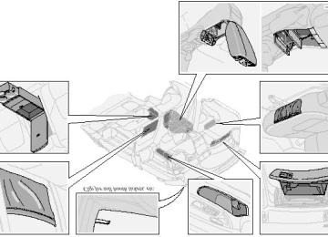
Replacing high/low beam headlight bulbs
The headlight bulbs must be replaced from the engine compartment.
CAUTION: · Do not touch the glass on halogen bulbs with your fingers. Grease, oil or any other impurities can be carbonized onto the bulb and cause damage to the reflector. · Be sure to use bulbs of the correct type and voltage.
To remove a defective bulb:
· Switch off the ignition. · Open the hood. · Remove the plastic cover over the bulb (1) by turning it counterclockwise. · Remove the connector (2). · Loosen the retaining spring (3) by first moving it to the right and then moving it down, out of the way. · Pull out the defective bulb. Note the position of the guide lug on the base of the bulb (4).
To install a new bulb:
· Insert the new bulb, without touching the glass, with the guide lug upward (1). The bulb will only seat properly in this position. · Move the retaining spring up and push it slightly to the left until it seats properly (2). · Press the connector into place on the bulb (3). · Reinstall the plastic cover and turn it clockwise until it is correctly in place (4). "TOP" must be upward.
NOTE: If the vertical aim of your headlights needs to be adjusted for any reason (e.g., towing a trailer for extended periods), this should be done by an authorized Volvo retailer.
pg.97 Replacing bulbs
Side direction indicator
· Open the front door halfway. · From the inside of the fender, push the lamp housing out. · Turn the bulb holder 1/4 turn counterclockwise and pull it out from the lens. · Remove the defective bulb by pulling it straight out.
· Insert a new bulb. · Reinsert the bulb holder in the lens and press the entire lamp housing back into place on the fender.
Front parking lights/direction indicators
· Switch off the ignition. · Open the hood. · Press down the retaining catch with a screwdriver and pull out the lamp housing. · Press the retaining spring downward and pull the connector out of the lamp housing. · Turn the bulb holder counterclockwise and remove it. · Remove the defective bulb from the holder by first pressing it in slightly and then turning it counterclockwise. · Install a new bulb in the holder and reinsert the bulb and holder in the lamp housing.
· Press the connector onto the bulb holder. · Switch on the ignition to test the bulb. · Press the lamp housing back into place on the fender. Be sure it seats properly.
pg.98 Replacing bulbs
Tail lights
1. Brake light 2. Back-up light 3. Direction indicator 4/5. Tail lights 6. Fog light (left side only)
All tail light bulbs are accessed from inside the trunk. · Switch off the ignition and open the trunk. · Fold the covering panel inward to access the bulbs. When replacing right tail light bulbs, access is made easier if you pull out the cargo net in the trunk completely before folding down the panel.
The bulbs are located in upper and a lower holders. . Each holder has a retaining catch.
To replace a bulb in the upper holder:
· Disconnect the wiring from the bulb holder. · Press the retaining catch upward to release the lower part of the holder. · Press the retaining catch downward to release the upper part of the holder. · Replace the defective bulb. · Press the bulb holder back into place. · Reconnect the wiring. · Fold up and close the covering panel.
To replace a bulb in the lower holder:
· Disconnect the wiring from the bulb holder. · Press the retaining catch toward the outside of the car to release the holder. · Replace the defective bulb. · Press the bulb holder back into place. · Reconnect the wiring. · Fold up and close the covering panel.
pg.99 Replacing bulbs
Front fog lights (option)
CAUTION:
Avoid touching the glass on the bulb with your fingers.
· Switch off the ignition. · Turn the bulb holder slightly counterclockwise to release it. · Replace the bulb. The shape of the foot of the bulb corresponds to the shape of the bulb holder. · Reinstall the bulb holder by turning it slightly clockwise. "TOP" on the holder should be upward.
Vanity mirror lights
· Carefully insert a screwdriver and pry out the lens. · Pry out the bulb and replace it. · Carefully press the lower edge of lens onto the four tabs and press the upper edge of the lens into place.
pg.100 Replacing bulbs
License plate lights
· Switch off the ignition. · Loosen the screws with a torx screwdriver. · Carefully pull out the lamp housing. · Turn the bulb holder counterclockwise and pull it out. · Pull out the defective bulb and insert a new one. · Reinsert the bulb holder into the housing and turn it clockwise. · Reinstall the housing and screw it in place.
Door step courtesy lights
The door step courtesy lights are located under the dash on the driver's and passenger's sides. To replace a bulb: · Carefully insert a screwdriver and pry out the lens. · Replace the defective bulb. · Reinstall the lens.
Rear door step lights
· Carefully insert a screwdriver and pry out the lens.
· Disconnect the wiring from the lamp housing. · Remove the lens from the lamp housing by pressing the two side catches out. · Pull out the defective bulb and replace it. · Reinstall the lamp housing in the reverse order.
Contents | Top of Page
2 0 0 1 VOLVO
S80
Chapter 9 - Specifications
pg.121 Specifications
Label information 122
Dimensions and weights 123
Engine/transmission specifications 124
Oil/fluid specifications and volumes 125
Fuel system, Distributor ignition system, Suspension 126
Electrical system 127
Volvo On Call 128pg.122 Label information
1 Vehicle Emission Control Information
Your Volvo is designed to meet all applicable emission standards, as evidenced by the certification label on the underside of the hood. For further information regarding these regulations, please consult your Volvo retailer.
2 Vacuum hose routing (underside of hood)
3 Loads and Tire Pressures (on inside of fuel filler door)
4 Model plate
Vehicle Identification Number (VIN). Codes for color and upholstery, etc. The plate is located in the engine compartment, on the inside of the left front fender.
5 Vehicle Identification Number (VIN) *
The VIN plate is located on the top left surface of the dashboard. The VIN is also stamped on the right hand door pillar.
6 Federal Motor Vehicle Safety Standards (FMVSS) specifications (USA) and Ministry of Transport (CMVSS)
standards (Canada)
Your Volvo is designed to meet all applicable safety standards, as evidenced by the certification label on the facing side of the driver's door. For further information regarding these regulations, please consult your Volvo retailer.
7 Child safety latch label
* The Vehicle Identification Number (VIN) should always be quoted in all correspondence concerning your vehicle with the retailer and when ordering parts.
All specifications are subject to change without prior notice.
pg.123 Dimensions and weights
Dimensions Length Width Height Wheelbase Track, front Track, rear Turning circle (between curbs) 35.8 - 39 ft. (10.9 - 12 m) Cargo capacity - trunk
189.8 in. (482 cm) 72 in. (183 cm) 57.1 in. (145 cm) 109.8 in. (279 cm) 62.2 in. (158 cm) 61.4 in. (156 cm)
14.2 cu. ft. (0.4 m3)
Weights
USA Gross vehicle weight (GVW) 6 cyl. 6 cyl. turbo Capacity weight *
4608 lbs (2090 kg) 4670 lbs (2118 kg)
Canada
2090 kg 2120 kg
3585-3620 Ibs (1626-1642 kg) 1625-1640 kg 3655-3685 Ibs (1658-1671 kg) 1655-1675 kg
2491 Ibs (1129 kg)
890 lbs (400 kg) 890 lbs (400 kg)
6 cyl. 6 cyl. turbo Curb weight 6 cyl. 6 cyl. turbo Permissible axle weight, front 6 cyl. Permissible axle weight, rear 6 cyl. Max roof load Max trailer weight (w/o brakes) Max trailer weight (with brakes) 2" ball 1 7/8" ball Max tongue weight ** 165 lbs (75 kg)
1100 lbs (500 kg)
2293 lbs (1039 kg) 220 lbs (100 kg)
3300 lbs (1500 kg) 2000 lbs (908 kg)
400 kg 400 kg
1130 kg
1040 kg 100 kg
500 kg
1500 kg 900 kg 75 kg
WARNING!
When adding accessories, equipment, luggage and other cargo to your vehicle, the total loaded weight capacity of the vehicle must not be exceeded.
* The max permissible axle loads or the gross vehicle weight must not be exceeded.
** See also section "Trailer towing"
All specifications are subject to change without prior notice.
pg.124 Engine/transmission specifications
268 hp at 5400 rpm (200 KW/90 rps) 280 ft. lbs. at 2100-5000 rpm (380 Nm at 35-83 rps)
Engine specifications Designation: Volvo B 6284 T Output Max torque Number of cylinders 6
Bore Stroke Displacement Compression ratio Number of valves3.19" (81 mm) 3.54" (90 mm) 2.78 liters 8.5:1
24Charge air cooler (Intercooler)
Turbocharged engines employ a turbocompressor to force air into the engine inlet manifold and a charge air cooler to
197 hp at 6000 rpm (147 KW/100 rps) 207 ft. lbs. at 4200 rpm (280 Nm at 70 rps)
cool the compressed inlet air. The resulting increase in air flow raises pressure in the intake manifold and increases engine power over that developed by the normallyaspirated engine. The charge air cooler (which resembles a radiator) is located between the turbocompressor and inlet manifold. Designation: Volvo B 6294 S Output Max. torque Number of cylinders 6
Bore Stroke Displacement Compression ratio Number of valves3.27" (83 mm) 3.54" (90 mm) 2.92 liters 10.5:1
24Transmission specifications Automatic transmission Gear ratios: Engine: B 6284 T B 6294 S 1st gear 2nd gear 3rd gear 4 th gear 5 th gear Reverse 2.38:1
Final drive 3.29:12.92:1
1.57:1
1.00:1
0.70:13.27:1
1.76:1
1.12:1
0.79:12.67:1
3.69:1All specifications are subject to change without prior notice.
pg.125 Oil/fluid specifications and volumes
Engine oil
Meeting minimum ILSAC specification GF-2, including ACEA A1, API SJ, SJ/CF and SJ/Energy Conserving.
Extra oil additives must not be used unless advised by an authorized Volvo retailer.
Volume: (including filter): Normally-aspirated 6-cylinder engine - 7.3 US qts (6.9 liters). Turbo 6-cylinder engine - 7.3 US qts (6.9 liters).
Automatic transmission fluid
Geartronic: ATF Dexron® III. AW5: Only Volvo gearbox oil (1161540-8). Do not mix with other oils.
Volume: 7.9 US qts (7.5 liters).
Cooling system
Type: Positive pressure, closed system. The thermostat begins to open at 194 °F (90 °C). Coolant: Volvo original coolant/antifreeze.
Volume: Normally-aspirated 6-cylinder engine - 9.3 US qts (8.8 liters). Turbo 6-cylinder engine - 10.1 US qts (9.6 liters).
Power steering fluid
ATF fluid.
Volume:6 cyl engine - 0.95 US qt (0.9 liter).
Brake fluid
DOT 4+
Volume: 0.6 US qt (0.6 liter)
Climate control system - refrigerant (R 134a)
Oil: PAG
Volume: 2.2 lbs (1000 g) R134a.
Fuel
Minimum octane requirement - AKI 87 (RON 91)
Volume (fuel tank): 21.1 US gals (80 liters)
Washer fluid reservoir
Volume: 6 cyl: 4.7 US qts. (4.5 liters)
All specifications are subject to change without prior notice.
pg.126 Fuel system, Distributor ignition system, Suspension
Fuel system
The engine is equipped with a multiport fuel injection system.
Distributor ignition system
Firing order: Distributor ignition setting: Not adjustable Spark plugs:
15-3-6-2-4
Spark plug gap: Tightening torque:
Replacing spark plugs
B 6284 T: P/N 271367-4 (or equivalent) B 6294 S: P/N 272371-8 (or equivalent) 0.028-0.032" (0.7-0.8 mm) 18.4 ft. lbs. (25 Nm)
The spark plugs should be changed every 30,000 miles (48,000 km). However, city driving or fast highway driving may necessitate changing after 15,000 miles (24,000 km) of driving. When installing new plugs, be sure to fit the right type and use correct torque. When changing the plugs, check that the suppressor connectors are in good condition. Cracked or damaged connectors should be replaced. When changing the spark plugs, clean the terminals and the rubber seals.
WARNING!
The distributor ignition system operates at very high voltages. Special safety precautions must be followed to prevent injury. Always turn the ignition off when:
· Replacing distributor ignition components e.g. plugs, coil, etc.
· Do not touch any part of the distributor ignition system while the engine is running. This may result in unintended movements and body injury.
Front suspension
Spring strut suspension with integrated shock absorbers and control arms linked to the support frame. Powerassisted rack and pinion steering. Safety type steering column.
The alignment specifications apply to an unladen car but include fuel, coolant and spare wheel.
Toe-in measured on the wheel rims: 2.3 mm +/ 0.8 mm
Toe-in measured on tire sides: 2.8 +/ 0.9 mm
Rear suspension
Individual rear wheel suspension with longitudinal support arms, double link arms and track rods.
Toe-in measured on the tire sides: 1.9 mm +/ 1.9 mm
Vehicle loading
The tires on your Volvo should perform to specifications at all normal loads when inflated as recommended on the tire information label. The label is located on the inside of the fuel tank cover. The label lists both tire and vehicle design limits. Do not load your car beyond the load limits indicated.
WARNING!
Improperly inflated tires will reduce tire life, adversely affect vehicle handling and can possibly lead to failure resulting in loss of vehicle control without prior warning.
All specifications are subject to change without prior notice.
pg.127 Electrical system
Electrical system
12 Volt, negative ground.
Voltagecontrolled generator. Singlewire system with chassis and engine used as conductors. Grounded on chassis.
Battery
Voltage: 12 Volt, capacity: 600 A/115 min.
The battery contains corrosive and poisonous acids. It is of the utmost importance that old batteries are disposed of correctly. Your Volvo retailer can assist you in this matter.
Generator
Rated output: max. current: 120 A
Starter motor:
Output: 1.7 kW
H7
H7Socket
55W 55W
US no. Power
W2.1x9.5d BAU 15 s
55 W 3 W 21W 5W/4cp BA 15 s 21W/32cp BA 15 s 21W/32cp BA 15 s 21W/32cp BA 15 s 5 W
Bulbs Bulb Headlights High beam Low beam Front parking lights/ 1157NA 21/5 W BAY 15d direction indicators H1
Front fog lights Side marker lights Rear direction indicators - Tail lights Brake lights Backup lights Rear fog light License plate light Door step courtesy lights Front Rear Trunk lights Glove compartment light - Vanity mirror lights Instrument lighting Rear ashtray Front courtesy lights Rear reading lights Sideview mirrorSV 8.5
W 2.1x9.5d SV 8.5
BA 9s SV 5.5
W 2.1x9.5d W 2x4.6d SV 8.5
W2.1x9.5d W2.1x9.5d5W 5W 10 W 2 W 1.2 W 3 W 1.2 W 10 W 5 W 5W
67
1156
1156
1156W 2.1x9.5d
All specifications are subject to change without prior notice.
pg.128 Volvo On Call
Your new Volvo comes with a four year ON CALL road assistance. Additional information, features, and benefits are described in a separate information package in your glove compartment. If you have misplaced your package, dial:
In the U.S.A.
1-800-63-VOLVO (1-800-638-6586)
In Canada:
1-800-263-0475
Volvo supports Voluntary Mechanic Certification by the A.S.E. (pertains to the USA only). Certified mechanics have demonstrated a high degree of competence in specific areas. Besides passing exams each mechanic must also have worked in the field for two or more years before a certificate is issued. These professional mechanics are fully able to analyze vehicle problems and perform the necessary service procedures to keep your Volvo at peak operating condition. All specifications are subject to change without prior notice.
Contents | Top of Page
2 0 0 1 VOLVO
S80
Chapter 10 - Audio systems
pg.129 Audio systems
HU-611 overview 130
HU-801 overview 131
Functions 132
Specifications 144
General information 145
HomeLink¨ Unversal Transceiver (option) 146NOTE: The text on the face of the radio, describing the button functions, may vary slightly depending on which audio system you have in your car.
pg.130 Audio system HU-611 - overview
1. On/off - press Volume - turn 2. Selector knob for: Stored radio frequencies CD changer - selecting disc 3. Selector knob: Radio Cassette
CD CD changer TV (option on certain models) 4. Fader - press and turn Balance - press, pull and turn 5. Radio - Station seek up/down Cassette - selecting next/previous track CD - Selecting next/previous track 6. Radio - Manual station selection Cassette - Fast winding forward/backward CD - Fast forwards/backward 7. CD eject 8. CD slot 9. CD random play 10. Active Sound Control (ON or OFF) 11. Scan function 12. Dolby B Noise Reduction 13. Automatic presetting of radio stations 14. Bass - press and turn Treble - press, pull and turn 15. Tape direction selector 16. Cassette opening 17. Cassette eject 18. Display
pg.131 Audio system HU-801 - overview
1. On/off - press Volume - turn 2. Bass - press and turn Treble - press, pull and turn 3. Fader - press and turn Balance - press, pull and turn 4. Center volume - press and turn Effect channel volume - press, pull and turn 5. Selector knob for: Stored radio frequencies CD - selecting disc 6. Selector knob: Radio
Internal CD changer CD Station scan - press TV (option on certain models) External CD changer (option) 7. Radio - Station seek up/down CD - Selecting next/previous track 8. Radio - Manual station selection CD - Fast forward/backward 9. CD eject 10. Dolby Pro Logic - switching on 11. 2 channel stereo 12 3 channel stereo 13. CD slot 14. CD random play 15. Program type Active Sound Control (ON or OFF) 16. News 17. Traffic information 18. Automatic presetting of radio stations 19. Display
pg.132 Audio systems HU-611/HU-801
Switch on/off
Press the knob to switch on or turn off the radio.
Volume control
Turn the knob clockwise to increase volume. Volume control is electronic and does not have an end stop. If you have a key pad in the steering wheel, increase or decrease the volume with the + or- buttons.
Bass