- 2000 Volvo S80 Owners Manuals
- Volvo S80 Owners Manuals
- 2003 Volvo S80 Owners Manuals
- Volvo S80 Owners Manuals
- 2004 Volvo S80 Owners Manuals
- Volvo S80 Owners Manuals
- 2007 Volvo S80 Owners Manuals
- Volvo S80 Owners Manuals
- 2013 Volvo S80 Owners Manuals
- Volvo S80 Owners Manuals
- 2010 Volvo S80 Owners Manuals
- Volvo S80 Owners Manuals
- 2002 Volvo S80 Owners Manuals
- Volvo S80 Owners Manuals
- 2005 Volvo S80 Owners Manuals
- Volvo S80 Owners Manuals
- 2008 Volvo S80 Owners Manuals
- Volvo S80 Owners Manuals
- 2009 Volvo S80 Owners Manuals
- Volvo S80 Owners Manuals
- 2012 Volvo S80 Owners Manuals
- Volvo S80 Owners Manuals
- 1999 Volvo S80 Owners Manuals
- Volvo S80 Owners Manuals
- 2011 Volvo S80 Owners Manuals
- Volvo S80 Owners Manuals
- 2006 Volvo S80 Owners Manuals
- Volvo S80 Owners Manuals
- 2001 Volvo S80 Owners Manuals
- Volvo S80 Owners Manuals
- Download PDF Manual
-
Headlight switch module, module for electrical connections, climate control system, onboard diagnostic connector , steering wheel lever modules Relay for extended X-feed: climate control system, power driver's seat, text window, shiftlock geartronic
Amperage 10A 10A 15A 20A 30A 30A 15A 15A 5A 15A 15A 15A 20A 5A 5A
30A 15A 15A 15A 10A 20A 5A
10A
25
26
27
28
29
30
31
32
33
34
35
36
37
3810A Ignition switch, Relay starter motor 30A Control module - climate control blower Central locking system, power windows, defroster, lighting, sideview mirrors, 15A door warning lights, power sideview mirrors 10A Power sun roof, courtesy lights, vanity mirror lights 10A Telephone (option) 10A Left front/rear parking lights 10A Right front/rear parking lights, license plate lights Central electrical module, vanity mirror lighting, interior courtesy lights, 10A power steering 15A Fuel pump 15A Power sun roof 25A Central locking system, power windows - left front Defroster, Lighting, Sideview mirrors, central locking system, power windows - right front 25A 30A Power windows - rear doors, child safety locks Siren alarm 5A
pg.95 Fuses in the trunk
Fuses in the trunk
The fuses in the trunk are located behind the left panel. When replacing a blown fuse, be sure to replace it with a new one of the same color and amperage (written on the fuse). Ordinary fuses
Location
Rear electrical module, trunk lights Rear fog light Brake lights Backup lights Rear window heater
Amperage 10A 10A 15A 10A 5A
6
10
11
12
13
14
15
16
17
1810A Trunk release Folding rear outboard head restraints 10A Central locking system - rear doors/fuel filler door 15A Traailer (30 supply) 20A CD changer, CD ROM, VNS, antenna 10A Trailer (15 supply)
15A
pg.96 Replacing bulbs
Replacing high/low beam headlight bulbs
The headlight bulbs must be replaced from the engine compartment.
CAUTION: · Do not touch the glass on halogen bulbs with your fingers. Grease, oil or any other impurities can be carbonized onto the bulb and cause damage to the reflector. · Be sure to use bulbs of the correct type and voltage.
To remove a defective bulb:
· Switch off the ignition. · Open the hood. · Remove the plastic cover over the bulb (1) by turning it counterclockwise. · Remove the connector (2). · Loosen the retaining spring (3) by first moving it to the right and then moving it down, out of the way. · Pull out the defective bulb. Note the position of the guide lug on the base of the bulb (4).
To install a new bulb:
· Insert the new bulb, without touching the glass, with the guide lug upward (1). The bulb will only seat properly in this position. · Move the retaining spring up and push it slightly to the left until it seats properly (2). · Press the connector into place on the bulb (3). · Reinstall the plastic cover and turn it clockwise until it is correctly in place (4). "TOP" must be upward.
NOTE: If the vertical aim of your headlights needs to be adjusted for any reason (e.g., towing a trailer for extended periods), this should be done by an authorized Volvo retailer.
pg.97 Replacing bulbs
Side direction indicator
· Open the front door halfway. · From the inside of the fender, push the lamp housing out. · Turn the bulb holder 1/4 turn counterclockwise and pull it out from the lens. · Remove the defective bulb by pulling it straight out.
· Insert a new bulb. · Reinsert the bulb holder in the lens and press the entire lamp housing back into place on the fender.
Front parking lights/direction indicators
· Switch off the ignition. · Open the hood. · Press down the retaining catch with a screwdriver and pull out the lamp housing. · Press the retaining spring downward and pull the connector out of the lamp housing. · Turn the bulb holder counterclockwise and remove it. · Remove the defective bulb from the holder by first pressing it in slightly and then turning it counterclockwise. · Install a new bulb in the holder and reinsert the bulb and holder in the lamp housing.
· Press the connector onto the bulb holder. · Switch on the ignition to test the bulb. · Press the lamp housing back into place on the fender. Be sure it seats properly.
pg.98 Replacing bulbs
Tail lights
1. Brake light 2. Back-up light 3. Direction indicator 4/5. Tail lights 6. Fog light (left side only)
All tail light bulbs are accessed from inside the trunk. · Switch off the ignition and open the trunk. · Fold the covering panel inward to access the bulbs. When replacing right tail light bulbs, access is made easier if you pull out the cargo net in the trunk completely before folding down the panel.
The bulbs are located in upper and a lower holders. . Each holder has a retaining catch.
To replace a bulb in the upper holder:
· Disconnect the wiring from the bulb holder. · Press the retaining catch upward to release the lower part of the holder. · Press the retaining catch downward to release the upper part of the holder. · Replace the defective bulb. · Press the bulb holder back into place. · Reconnect the wiring. · Fold up and close the covering panel.
To replace a bulb in the lower holder:
· Disconnect the wiring from the bulb holder. · Press the retaining catch toward the outside of the car to release the holder. · Replace the defective bulb. · Press the bulb holder back into place. · Reconnect the wiring. · Fold up and close the covering panel.
pg.99 Replacing bulbs
Front fog lights (option)
CAUTION:
Avoid touching the glass on the bulb with your fingers.
· Switch off the ignition. · Turn the bulb holder slightly counterclockwise to release it. · Replace the bulb. The shape of the foot of the bulb corresponds to the shape of the bulb holder. · Reinstall the bulb holder by turning it slightly clockwise. "TOP" on the holder should be upward.
Vanity mirror lights
· Carefully insert a screwdriver and pry out the lens. · Pry out the bulb and replace it. · Carefully press the lower edge of lens onto the four tabs and press the upper edge of the lens into place.
pg.100 Replacing bulbs
License plate lights
· Switch off the ignition. · Loosen the screws with a torx screwdriver. · Carefully pull out the lamp housing. · Turn the bulb holder counterclockwise and pull it out. · Pull out the defective bulb and insert a new one. · Reinsert the bulb holder into the housing and turn it clockwise. · Reinstall the housing and screw it in place.
Door step courtesy lights
The door step courtesy lights are located under the dash on the driver's and passenger's sides. To replace a bulb: · Carefully insert a screwdriver and pry out the lens. · Replace the defective bulb. · Reinstall the lens.
Rear door step lights
· Carefully insert a screwdriver and pry out the lens.
· Disconnect the wiring from the lamp housing. · Remove the lens from the lamp housing by pressing the two side catches out. · Pull out the defective bulb and replace it. · Reinstall the lamp housing in the reverse order.
Contents | Top of Page
2 0 0 1 VOLVO
S80
Chapter 9 - Specifications
pg.121 Specifications
Label information 122
Dimensions and weights 123
Engine/transmission specifications 124
Oil/fluid specifications and volumes 125
Fuel system, Distributor ignition system, Suspension 126
Electrical system 127
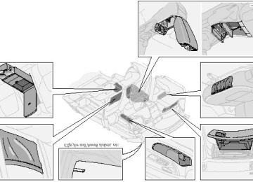
Volvo On Call 128pg.122 Label information
1 Vehicle Emission Control Information
Your Volvo is designed to meet all applicable emission standards, as evidenced by the certification label on the underside of the hood. For further information regarding these regulations, please consult your Volvo retailer.
2 Vacuum hose routing (underside of hood)
3 Loads and Tire Pressures (on inside of fuel filler door)
4 Model plate
Vehicle Identification Number (VIN). Codes for color and upholstery, etc. The plate is located in the engine compartment, on the inside of the left front fender.
5 Vehicle Identification Number (VIN) *
The VIN plate is located on the top left surface of the dashboard. The VIN is also stamped on the right hand door pillar.
6 Federal Motor Vehicle Safety Standards (FMVSS) specifications (USA) and Ministry of Transport (CMVSS)
standards (Canada)
Your Volvo is designed to meet all applicable safety standards, as evidenced by the certification label on the facing side of the driver's door. For further information regarding these regulations, please consult your Volvo retailer.
7 Child safety latch label
* The Vehicle Identification Number (VIN) should always be quoted in all correspondence concerning your vehicle with the retailer and when ordering parts.
All specifications are subject to change without prior notice.
pg.123 Dimensions and weights
Dimensions Length Width Height Wheelbase Track, front Track, rear Turning circle (between curbs) 35.8 - 39 ft. (10.9 - 12 m) Cargo capacity - trunk
189.8 in. (482 cm) 72 in. (183 cm) 57.1 in. (145 cm) 109.8 in. (279 cm) 62.2 in. (158 cm) 61.4 in. (156 cm)
14.2 cu. ft. (0.4 m3)
Weights
USA Gross vehicle weight (GVW) 6 cyl. 6 cyl. turbo Capacity weight *
4608 lbs (2090 kg) 4670 lbs (2118 kg)
Canada
2090 kg 2120 kg
3585-3620 Ibs (1626-1642 kg) 1625-1640 kg 3655-3685 Ibs (1658-1671 kg) 1655-1675 kg
2491 Ibs (1129 kg)
890 lbs (400 kg) 890 lbs (400 kg)
6 cyl. 6 cyl. turbo Curb weight 6 cyl. 6 cyl. turbo Permissible axle weight, front 6 cyl. Permissible axle weight, rear 6 cyl. Max roof load Max trailer weight (w/o brakes) Max trailer weight (with brakes) 2" ball 1 7/8" ball Max tongue weight ** 165 lbs (75 kg)
1100 lbs (500 kg)
2293 lbs (1039 kg) 220 lbs (100 kg)
3300 lbs (1500 kg) 2000 lbs (908 kg)
400 kg 400 kg
1130 kg
1040 kg 100 kg
500 kg
1500 kg 900 kg 75 kg
WARNING!
When adding accessories, equipment, luggage and other cargo to your vehicle, the total loaded weight capacity of the vehicle must not be exceeded.
* The max permissible axle loads or the gross vehicle weight must not be exceeded.
** See also section "Trailer towing"
All specifications are subject to change without prior notice.
pg.124 Engine/transmission specifications
268 hp at 5400 rpm (200 KW/90 rps) 280 ft. lbs. at 2100-5000 rpm (380 Nm at 35-83 rps)
Engine specifications Designation: Volvo B 6284 T Output Max torque Number of cylinders 6
Bore Stroke Displacement Compression ratio Number of valves3.19" (81 mm) 3.54" (90 mm) 2.78 liters 8.5:1
24Charge air cooler (Intercooler)
Turbocharged engines employ a turbocompressor to force air into the engine inlet manifold and a charge air cooler to
197 hp at 6000 rpm (147 KW/100 rps) 207 ft. lbs. at 4200 rpm (280 Nm at 70 rps)
cool the compressed inlet air. The resulting increase in air flow raises pressure in the intake manifold and increases engine power over that developed by the normallyaspirated engine. The charge air cooler (which resembles a radiator) is located between the turbocompressor and inlet manifold. Designation: Volvo B 6294 S Output Max. torque Number of cylinders 6
Bore Stroke Displacement Compression ratio Number of valves3.27" (83 mm) 3.54" (90 mm) 2.92 liters 10.5:1
24Transmission specifications Automatic transmission Gear ratios: Engine: B 6284 T B 6294 S 1st gear 2nd gear 3rd gear 4 th gear 5 th gear Reverse 2.38:1
Final drive 3.29:12.92:1
1.57:1
1.00:1
0.70:13.27:1
1.76:1
1.12:1
0.79:12.67:1
3.69:1All specifications are subject to change without prior notice.
pg.125 Oil/fluid specifications and volumes
Engine oil
Meeting minimum ILSAC specification GF-2, including ACEA A1, API SJ, SJ/CF and SJ/Energy Conserving.
Extra oil additives must not be used unless advised by an authorized Volvo retailer.
Volume: (including filter): Normally-aspirated 6-cylinder engine - 7.3 US qts (6.9 liters). Turbo 6-cylinder engine - 7.3 US qts (6.9 liters).
Automatic transmission fluid
Geartronic: ATF Dexron® III. AW5: Only Volvo gearbox oil (1161540-8). Do not mix with other oils.
Volume: 7.9 US qts (7.5 liters).
Cooling system
Type: Positive pressure, closed system. The thermostat begins to open at 194 °F (90 °C). Coolant: Volvo original coolant/antifreeze.
Volume: Normally-aspirated 6-cylinder engine - 9.3 US qts (8.8 liters). Turbo 6-cylinder engine - 10.1 US qts (9.6 liters).
Power steering fluid
ATF fluid.
Volume:6 cyl engine - 0.95 US qt (0.9 liter).
Brake fluid
DOT 4+
Volume: 0.6 US qt (0.6 liter)
Climate control system - refrigerant (R 134a)
Oil: PAG
Volume: 2.2 lbs (1000 g) R134a.
Fuel
Minimum octane requirement - AKI 87 (RON 91)
Volume (fuel tank): 21.1 US gals (80 liters)
Washer fluid reservoir
Volume: 6 cyl: 4.7 US qts. (4.5 liters)
All specifications are subject to change without prior notice.
pg.126 Fuel system, Distributor ignition system, Suspension
Fuel system
The engine is equipped with a multiport fuel injection system.
Distributor ignition system
Firing order: Distributor ignition setting: Not adjustable Spark plugs:
15-3-6-2-4
Spark plug gap: Tightening torque:
Replacing spark plugs
B 6284 T: P/N 271367-4 (or equivalent) B 6294 S: P/N 272371-8 (or equivalent) 0.028-0.032" (0.7-0.8 mm) 18.4 ft. lbs. (25 Nm)
The spark plugs should be changed every 30,000 miles (48,000 km). However, city driving or fast highway driving may necessitate changing after 15,000 miles (24,000 km) of driving. When installing new plugs, be sure to fit the right type and use correct torque. When changing the plugs, check that the suppressor connectors are in good condition. Cracked or damaged connectors should be replaced. When changing the spark plugs, clean the terminals and the rubber seals.
WARNING!
The distributor ignition system operates at very high voltages. Special safety precautions must be followed to prevent injury. Always turn the ignition off when:
· Replacing distributor ignition components e.g. plugs, coil, etc.
· Do not touch any part of the distributor ignition system while the engine is running. This may result in unintended movements and body injury.
Front suspension
Spring strut suspension with integrated shock absorbers and control arms linked to the support frame. Powerassisted rack and pinion steering. Safety type steering column.
The alignment specifications apply to an unladen car but include fuel, coolant and spare wheel.
Toe-in measured on the wheel rims: 2.3 mm +/ 0.8 mm
Toe-in measured on tire sides: 2.8 +/ 0.9 mm
Rear suspension
Individual rear wheel suspension with longitudinal support arms, double link arms and track rods.
Toe-in measured on the tire sides: 1.9 mm +/ 1.9 mm
Vehicle loading
The tires on your Volvo should perform to specifications at all normal loads when inflated as recommended on the tire information label. The label is located on the inside of the fuel tank cover. The label lists both tire and vehicle design limits. Do not load your car beyond the load limits indicated.
WARNING!
Improperly inflated tires will reduce tire life, adversely affect vehicle handling and can possibly lead to failure resulting in loss of vehicle control without prior warning.
All specifications are subject to change without prior notice.
pg.127 Electrical system
Electrical system
12 Volt, negative ground.
Voltagecontrolled generator. Singlewire system with chassis and engine used as conductors. Grounded on chassis.
Battery
Voltage: 12 Volt, capacity: 600 A/115 min.
The battery contains corrosive and poisonous acids. It is of the utmost importance that old batteries are disposed of correctly. Your Volvo retailer can assist you in this matter.
Generator
Rated output: max. current: 120 A
Starter motor:
Output: 1.7 kW
H7
H7Socket
55W 55W
US no. Power
W2.1x9.5d BAU 15 s
55 W 3 W 21W 5W/4cp BA 15 s 21W/32cp BA 15 s 21W/32cp BA 15 s 21W/32cp BA 15 s 5 W
Bulbs Bulb Headlights High beam Low beam Front parking lights/ 1157NA 21/5 W BAY 15d direction indicators H1
Front fog lights Side marker lights Rear direction indicators - Tail lights Brake lights Backup lights Rear fog light License plate light Door step courtesy lights Front Rear Trunk lights Glove compartment light - Vanity mirror lights Instrument lighting Rear ashtray Front courtesy lights Rear reading lights Sideview mirrorSV 8.5
W 2.1x9.5d SV 8.5
BA 9s SV 5.5
W 2.1x9.5d W 2x4.6d SV 8.5
W2.1x9.5d W2.1x9.5d5W 5W 10 W 2 W 1.2 W 3 W 1.2 W 10 W 5 W 5W
67
1156
1156
1156W 2.1x9.5d
All specifications are subject to change without prior notice.
pg.128 Volvo On Call
Your new Volvo comes with a four year ON CALL road assistance. Additional information, features, and benefits are described in a separate information package in your glove compartment. If you have misplaced your package, dial:
In the U.S.A.
1-800-63-VOLVO (1-800-638-6586)
In Canada:
1-800-263-0475
Volvo supports Voluntary Mechanic Certification by the A.S.E. (pertains to the USA only). Certified mechanics have demonstrated a high degree of competence in specific areas. Besides passing exams each mechanic must also have worked in the field for two or more years before a certificate is issued. These professional mechanics are fully able to analyze vehicle problems and perform the necessary service procedures to keep your Volvo at peak operating condition. All specifications are subject to change without prior notice.
Contents | Top of Page
2 0 0 1 VOLVO
S80
Chapter 10 - Audio systems
pg.129 Audio systems
HU-611 overview 130
HU-801 overview 131
Functions 132
Specifications 144
General information 145
HomeLink¨ Unversal Transceiver (option) 146NOTE: The text on the face of the radio, describing the button functions, may vary slightly depending on which audio system you have in your car.
pg.130 Audio system HU-611 - overview
1. On/off - press Volume - turn 2. Selector knob for: Stored radio frequencies CD changer - selecting disc 3. Selector knob: Radio Cassette
CD CD changer TV (option on certain models) 4. Fader - press and turn Balance - press, pull and turn 5. Radio - Station seek up/down Cassette - selecting next/previous track CD - Selecting next/previous track 6. Radio - Manual station selection Cassette - Fast winding forward/backward CD - Fast forwards/backward 7. CD eject 8. CD slot 9. CD random play 10. Active Sound Control (ON or OFF) 11. Scan function 12. Dolby B Noise Reduction 13. Automatic presetting of radio stations 14. Bass - press and turn Treble - press, pull and turn 15. Tape direction selector 16. Cassette opening 17. Cassette eject 18. Display
pg.131 Audio system HU-801 - overview
1. On/off - press Volume - turn 2. Bass - press and turn Treble - press, pull and turn 3. Fader - press and turn Balance - press, pull and turn 4. Center volume - press and turn Effect channel volume - press, pull and turn 5. Selector knob for: Stored radio frequencies CD - selecting disc 6. Selector knob: Radio
Internal CD changer CD Station scan - press TV (option on certain models) External CD changer (option) 7. Radio - Station seek up/down CD - Selecting next/previous track 8. Radio - Manual station selection CD - Fast forward/backward 9. CD eject 10. Dolby Pro Logic - switching on 11. 2 channel stereo 12 3 channel stereo 13. CD slot 14. CD random play 15. Program type Active Sound Control (ON or OFF) 16. News 17. Traffic information 18. Automatic presetting of radio stations 19. Display
pg.132 Audio systems HU-611/HU-801
Switch on/off
Press the knob to switch on or turn off the radio.
Volume control
Turn the knob clockwise to increase volume. Volume control is electronic and does not have an end stop. If you have a key pad in the steering wheel, increase or decrease the volume with the + or- buttons.
Bass
Adjust the bass by pressing the button to extend the control and turning it to the left (less bass) or to the right (more bass). A "detent" indicates "equalized" bass. Press the button back in when you have made the adjustment.
Treble
Adjust the treble by pressing the button to extend the control, pulling it out as far as possible, and then turning it to the left
(less treble) or to the right (more treble). A "detent" indicates "equalized" treble. Press the button back in when you have made the adjustment.
Wavelength selector
Turn "SOURCE" knob to select FM or AM. The station and wavelength are displayed. You can also select cassette deck, CD or CD changer, if connected, with this knob.
Active sound control (ASC)
The ASC (Active Sound Control) automatically adapts volume to vehicle speed.
Press the ASC button (HU-611) or the PTY button (HU-801) for several seconds to switch this function ON or OFF.
This function is included in the Advanced User Mode on the HU-801 equipped with this feature.
"ASC ON" or "ASC OFF" will be shown in the display for several seconds.
pg.133 Audio systems HU-611/HU-801
Fader - Balance front/rear
Adjust front/rear speaker balance by pressing the button to extend the control and turning it to the left (more sound from the rear speakers) or to the right (more sound from the front speakers). A "detent" indicates "equalized" balance. Press the button back in when you have made the adjustment.
Balance right/left
Adjust left/right speaker balance by pressing the button to extend the control, pulling it out as far as possible and then turning it to the left (more sound from the left speakers) or to the right (more sound from the right speakers). A
"detent" indicates "equalized" balance. Press the button back in when you have made the adjustment.
A - Setting station
Press the left side of the button to select lower frequencies and the right side for higher frequencies. Set frequencies are displayed.
B - Station seek up/down
Press the left side (lower frequency) or right side (higher frequency) of the button to start the seek function. The radio seeks the next audible station and tunes it in. Repeat the procedure to continue the seek function.
Audio system controls on the steering wheel
Station seek up/down
If you have a key pad in the steering wheel press the right or left arrow to switch between preset stations.
Scan function
Press the SCAN button (HU-611) or the SOURCE button (HU-801) to start the station scan function. When a station is found, scanning stops for several seconds, after which scanning will continue.
Press the SCAN or SOURCE button when a station has been found if you would like to listen to that station and to discontinue the scan function.
pg.134 Audio systems HU-611/HU-801 - radio
A - Automatic station preset
This function seeks and stores up to 10 strong AM or FM stations in a separate memory. This function is especially useful in areas where you are not familiar with the radio stations.
1. Press in the "AUTO" button. A number of strong signal stations (max. 10) from the currently selected waveband are now stored automatically in the memory. An "A" and "AUTO" is displayed. If there is no station with sufficient signal strength "NO STATION" is displayed.
2. Turn "1-20/DISC" button if you wish to change to another of the auto-stored stations.
Another auto-stored station is selected with each turn.
Programming stations
1. Tune in the desired frequency.
2. Press the "1-20/DISC" button. Select a number by turning forwards or backwards. Press again to store the selected frequency and station.
Preset
To choose a pre-set station, turn "1-20/DISC" button to the stored number. The currently selected station is displayed. Radio Data System (RDS, also referred to as RBDS) - HU-801 only
The HU-801 radio in your car is equipped with an advanced system allowing information from broadcasters to be transmitted visually, as text, together with the audio signal. This information is then decoded by the radio and made available for several new and unique features. The RDS or Radio Data System operates in the FM band only, and the information transmitted is supplied exclusively by participating broadcasters. Volvo has no control over the accuracy of the data or information. Please refer to the following pages regarding specific descriptions and operation of these functions.
Volvo was among the first to pioneer this technology throughout Europe and it is slowly making its way to North America. Coverage by local broadcasters may be limited at this time, but as the technology and benefits grow, you will find the radio in your car is equipped to take advantage of this system.
pg.135 Audio systems HU-801 - radio
Traffic information (TP) - HU-801 only
This feature may not be apply in your area and only functions with FM broadcasts.
Push the "TP" button for traffic information from RDS stations. "TP" is displayed when the function is connected.
When the unit is in Cassette or CD mode, the FM radio function will seek in the background for a station with a strong signal broadcasting traffic information. If a cassette or CD are playing when the radio receives a traffic bulletin, that function is interrupted and the bulletin is broadcast with the volume pre-selected for traffic information.
When the bulletin is finished the unit immediately returns to the previously set volume and continues playing the cassette or CD.
· Traffic information can only be heard when
is displayed.
· If only TP is displayed, this indicates that no traffic information is being received at the time.
· If you do not wish to listen to an ongoing traffic bulletin, press the "TP" button. The TP function will remain active and the radio will continue to monitor traffic information.
· To turn the TP function off, press the TP button. TP is no longer shown in the display.
News on/off - HU-801 only
This feature may not be apply in your area and only functions with FM broadcasts.
Press the "NEWS" button to activate the news function. The text NEWS is displayed. Press the "NEWS" button again if you want to switch off the function.
As soon as a news broadcast begins, the news program will interrupt the Cassette, CD or CD changer.
If you do not wish to listen to the news program, press the "NEWS" button again. The news function will remain active and the radio will continue to monitor news programs.
pg.136 Audio systems HU-801 - radio
Program types (HU-801 only)
Text displayed News Inform Sports Talk Rock Cls_Rock Adlt_Hit Soft_Rck Top_40
Country Oldies Soft Nostalga Jazz Classicl R_&_BProgram type News Information Sports Talk Rock Classic rock Adult hits Soft rock Top 40
Country Oldies Soft Nostalgia Jazz Classical Rhythm and Blues Soft Rhythm and Blues Soft_R&B Language Foreign language Religious music Rel_Musc Rel_Talk Religious talk Persnlty Personality Public Public College College WeatherWeather
Contents | Top of Page
2 0 0 1 VOLVO
S80
HomeLink® Universal Transceiver (option)
pg.146 HomeLink® Universal Transceiver (option)
HomeLink® Universal Transceiver
HomeLink® is an advanced system that can be programmed to learn the codes of three different remote controlled- devices (e.g., garage door openers, remote lighting, entry door lock). HomeLink®'s sun visor-mounted transceiver, powered by your car's electrical system, may then be used in place of your hand-held remote controls..
NOTE: As a security precaution, the HomeLink® Universal Transceiver is designed to not function if the car has been locked from the outside.
Programming the transceiver
1. The ignition switch must be turned to the "accessory" position (II) before programming the HomeLink® Universal Transceiver.
2. Begin by erasing all 3 factory default channels. Hold down the two outside buttons (buttons 1 and 3 in the illustration) on the HomeLink® Universal Transceiver for about 20 seconds, until HomeLink®'s indicator light begins to flash. Then release the buttons.
3. Hold your hand-held transmitter (garage door opener, for example) 2 to 5 in. (5 to 12 cm) away from the HomeLink® surface, keeping the indicator light in view. For placement questions, contact HomeLink® toll-free 1- 800-355-3515 (Internet: www.HomeLink.jci.com).
4. Using two hands, push and hold both your hand-held transmitter's button and the transceiver button you wish to program. The indicator light will flash first slowly, then rapidly. Rapid flashing tells you the HomeLink® button has
been successfully programmed. Release both buttons.
5. If you are programming a rolling code-equipped device (e.g., garage door opener or entry door lock), refer to "Programming rolling codes" on the next page to complete the programming process. Repeat steps 3 and 4 to program the other two transceiver buttons. If, after several attempts, you are unable to successfully train the HomeLink® Universal Transceiver to learn your hand-held transmitter's signal, contact HomeLink® toll-free 1-800-355-3515
(Internet: www.HomeLink.jci.com).pg.147 HomeLink® Universal Transceiver (option)
WARNING!
· If you use HomeLink® to open a garage door or gate, be sure no one is near the gate or door while it is in motion.
· Do not use the HomeLink® Universal Transceiver with any garage door opener that lacks safety "stop" and "reverse" features as required by federal safety standards. (This includes any garage door opener model manufactured before April 1, 1982) A garage door opener that cannot "detect" an object, signalling the door to "stop" and "reverse" does not meet current federal safety standards. Using a garage door opener without these features increases the risk of serious injury or death. For more information on this matter, call toll-free 1-800-355- 3515 (Internet: www.HomeLink.jci.com).
NOTE - Canadian residents:
During programming, your hand-held transmitter may automatically stop transmitting. To successfully train HomeLink®, continue to hold the HomeLink® button. At the same time, repeatedly press and hold your hand-held transmitter's button at two-second intervals until HomeLink® has learned your transmitter's code. The HomeLink® indicator light will flash first slowly, and then rapidly to indicate that the button has been successfully programmed..
Programming rolling codes
Determine, in one of the following ways, if your garage door uses a rolling code system and is manufactured after 1996:
· Refer to the garage door opener owner's manual for verification.
· If your hand-held transmitter appears to program the HomeLink® Universal Transceiver but the programmed button does not activate the garage door, your garage door opener may have a rolling code.
· Press the programmed HomeLink® button. If the garage door opener has the rolling code feature, the HomeLink® indicator light flashes rapidly and then glows steadily after approximately 2 seconds.
To train a garage door opener with the rolling code feature, follow these instructions after the transceiver has been programmed (the aid of a second person may make the training quicker and easier):
1. Locate the training button on the garage door opener motor head unit. The exact location and color of the button may vary. If you encounter difficulty, refer to the garage door opener owner's manual or call: 1-800-355-3515
(Internet: www.HomeLink.jci.com).2. Press the "training" button on the garage door opener motor head unit until the "training" light comes on.
3. Firmly press and release the programmed HomeLink® button. Press and release the HomeLink® button a second time to complete the training process.
Some garage door openers may require you to do this procedure a third time to complete the training.
The programmed button on your HomeLink® Universal Transceiver should now operate your garage door opener. The original hand-held transmitter can also be used, if necessary, to operate the garage door.
The remaining two HomeLink® buttons can be programmed in the same way. In the event of any problems in programming the HomeLink® Universal Transceiver, call toll-free 1-800-355-3515 (Internet: www.HomeLink.jci.com).
Operating the HomeLink® Universal Transceiver
Once programmed, the HomeLink® Universal Transceiver can be used in place of hand-held transmitters.
To operate, the key must be turned to the "accessory" position (II) or the engine must be running. Press the programmed HomeLink® button to activate the garage door, driveway gate, security lighting, home security system, etc.
Your original hand-held transmitters may, of course, be used at any time.
pg.148 HomeLink® Universal Transceiver (option)
Erasing programmed buttons
Individual buttons cannot be erased. To erase all three programmed buttons:
1. Turn the ignition key to the "accessory" position (II).
2. Hold down the two outside buttons on the HomeLink® Universal Transceiver for about 20 seconds, until HomeLink®'s indicator light begins to flash.
3. Release both buttons.
The HomeLink® buttons can be reprogrammed using the procedures described on the previous pages.
Reprogramming a single HomeLink® button
1. Press and hold the desired HomeLink® button. Do not release the button until step 3 has been completed.
2. When the indicator light begins to flash slowly (after approximately 20 seconds), position the hand-held transmitter 2 to 5 in. (5 to 12 cm) away from the HomeLink® surface.
3. Press and hold the hand-held transmitter button. The HomeLink® indicator light will flash first slowly, then rapidly. When the indicator light flashes rapidly, release both buttons.
The previously programmed device has now been erased and the new device can be activated by pressing the HomeLink® button that has just been programmed. This procedure will not affect any other programmed HomeLink® buttons.
NOTE:
· Retain the original transmitter(s) for future programming procedures (i.e., if you purchase a new car).
· For your own security, erase all programmed buttons on the HomeLink® Universal Transceiver when you sell your car.
· Metallic sun protection films should not be used on any windows in a car equipped with HomeLink® Universal Transceiver. This could interfere with the transceiver's function.
Contents | Top of Page
2 0 0 1 VOLVO
S80
Index
pg.162 Index
ABS..........17
ABS - warning light..........25
Accessory lights..........27
Adjusting the steering wheel..........32
Advanced User Mode (AUM) - radio..........137
Air conditioning..........41, 42, 43, 45
Air pump system..........110
Air vents..........40
Airbag (SIPS)..........8
Airbag (SRS)..........4
Alarm..........60, 61
Alarm - "panic" function..........60
ALR/ELR..........14
Anti-lock Brake System (ABS)..........17
Anti-lock Brake System - warning light..........25
Antifreeze..........80, 110
Approach lighting..........56
Ashtrays..........34
Audio systems..........129
..cassette deck..........141
..CD player..........139
..HU-611 - overview..........130
..HU-801 - overview..........131
..radio..........134
..specifications..........144
AUM (Advanced User Mode) - radio..........137
Automatic car washing..........105
Automatic locking..........58
Automatic Locking Retractor (ALR)..........14
Automatic transmission..Geartronic..........69, 70
..Kickdown..........69
..Specifications..........124
Auxiliary socket..........27, 34
Backrests, rear seat - folding..........54
Battery..........80, 127
Battery maintenance..........117, 118
Replacing the battery..........118
Ventilation hose..........118
Blinds - rear/side rear windows..........38
Booster cushion..........13, 15
Booster cushion - integrated..........13
Brake failure warning light ..........24
Brake fluid..........116, 125
Brake system..........16
Break-in period..........64
Bulbs (list)..........127
Bulbs - replacing..........96-102
Capacities (oils and fluids)..........121, 125
Cargo net in trunk..........53
Catalytic converters - three-way..........82
Center console - switches..........27
Center head restraint - rear seat..........3
Central locking buttons..........59
Chains - winter driving..........85
Changing wheels..........88, 89
Child booster cushion ......... 13, 15
Child restraint anchorages ........ 12
Child safety..........12, 13, 14, 15
Child safety locks - rear doors..........62
Climate controls..........41, 42, 43, 45
Climate system - general information..........44
Clock..........23
Coat hanger..........49
Cold weather driving..........80
Combination filter..........41, 45
Coolant..........110, 125
Cooling system..........71, 125
Courtesy light..........50
Courtesy lights (front) - replacing..........102
Courtesy lights - exterior..........56
Cruise control..........29Cup holder - opening..........52
Dimensions..........123
Direction indicator bulbs (front)..........97
Direction indicators..........31
Distributor ignition system..........126
Door step courtesy lights - replacing..........100
Doors and locks..........56
Drive belt..........110
Driving economy..........71
Driving mode indicator..........23
Driving mode W..........68, 70, 80
Driving with trunk open..........72
Economical driving..........71
Electrical system..........127
Electrical system - general information..........72
Electrically operated front seats..........48
Electrically operated sideview mirrors..........36
Electrically operated sun roof..........37
Electrically operated windows..........35
Electronic Brake Force Distribution..........17
Electronic Climate Control (ECC)..........41, 42, 43, 45
Emergency Locking Retractor (ELR)..........14
Emergency towing..........74, 75
Emergency warning flashers..........33
Emissions systems..........109
Engine - specifications..........124
Engine - starting..........66
Engine compartment..........113
Engine oil..........64, 80, 114, 115, 125
Exterior courtesy lights..........56
Exterior features - overview..........21
Fog light - rear..........25, 30
Fog lights - front..........30
Folding head restraints..........27
Folding passenger's seat backrest..........49
Folding rear seat backrests ........54
Folding sideview mirrors..........27
Front airbags - SRS..........4-7
Front airbags - SRS - warning light..........24
Front courtesy lights - replacing..........102Front fog lights..........30
Front fog lights - replacing ........99
Front reading lights..........50
Front seats - adjusting..........48
Front seats - heated..........33
Front suspension..........126
Fuel..........64, 125
Fuel filler cap..........65
Fuel filler door..........65
Fuel gauge..........23
Fuel requirements..........64
Fuel system..........109, 126
Fuel/emissions systems..........109
Fuses..........92, 93, 94
Gas cap..........65
Gasoline..........64
Gear indicator..........23
Gear ratios..........124
Geartronic (automatic transmission)..........69, 70
Generator..........127
Generator warning light..........24
Hand brake..........34
Handling..........72
Hazard warning flashers..........33
Head restraint - center rear..........3
Head restraints, rear - folding..........27
Headlight bulbs - replacing..........96
Headlight wiper blades - replacing..........119
Headlights..........30
Heated front seats..........33
Heated rear window..........33
Heated sideview mirrors..........33
Heating..........41, 42, 43, 45
Hoisting the car..........112
Home Safe System..........56
HomeLink¨ ........146-148
Hood - opening..........113
Ignition switch..........32
Immobilizer (start inhibitor)..........56,66
Indicator lights..........24, 25
Inflatable curtain (IC)..........9Instrument illumination..........30
Instrument panel..........23
Instruments..........22
Integrated booster cushion ........ 13
Interior Air Quality system .........45
Interior features - overview..........20
Interior lighting..........50
Isofix fasteners..........12
Jack..........53, 88, 89
Jump starting..........79
Key - removing from ignition switch..........66
Keyless entry system..........57, 58
Keyless entry system - replacing batteries..........58
Keylock..........66
Keys..........56
Kickdown..........69
Label information..........122
License plate lights - replacing..........100
Lifting the car..........112
Lights - accessory..........27
Load carriers..........73
Locking - automatic..........58
Locking and unlocking the car..........56
Locking steering wheel..........32
Long distance trip..........81
Long loads..........49, 54
Maintenance schedule..........107, 108
Maintenance service..........106
Malfunction indicator lamp..........25
Memory function - front seats..........48
Mirrors..........36
Mirrors, sideview - folding 27
Mirrors, sideview - memory function..........36
Occupant safety..........11
Octane rating..........64
Odometer..........23
Oil - engine..........64, 80, 114, 115, 125
Oil pressure warning light ........ 24
Opening the hood..........113P Paint touch-up..........103
Panic function (alarm)..........60
Parking brake..........34
Parking brake reminder light..........24
Parking lights..........30
Passenger's seat backrest - folding..........49
Polishing..........105
Power seats..........48
Power steering - speed-sensitive..........72
Power steering fluid ........ 116, 125
Power windows..........35
PROPOSITION 65 WARNING..........117
Reading lights - front/rear ........ 50
Rear door step lights - replacing..........100
Rear fog light..........25, 30
Rear reading lights..........50
Rear seat backrests - folding..........54
Rear suspension..........126
Rear window - heated..........33
Rearview mirror..........36
Refrigerant..........44, 125
Refueling..........65
Remote control - keyless entry system..........57
Remote keyless entry system..........57
Remote keyless entry system - replacing batteries..........58
Replacing bulbs..........96-102
Replacing fuses..........92
Replacing wiper blades..........119
Reporting safety defects..........11
Road assistance..........128
Roadholding..........72
Roof load - maximum..........123
Roof racks..........73
Safety defects - reporting..........11
Safety locks - child..........62
Seat belt maintenance..........11
Seat belts..........2, 3, 14
Seat belts - cleaning..........105
Seats - front..........48
Servicing..........111, 112
Shiftlock..........66, 67, 69Side direction indicator - replacing..........99
Side impact airbag system (SIPS)..........8
Side marker lights - replacing..........101
Sideview mirrors..........36
Sideview mirrors - folding ........27
Sideview mirrors - heated..........33
Sideview mirrors - memory function..........36
Snow chains..........85
Snow tires..........85
Spare tire.......... 53, 86
Spark plugs..........126
Specifications..........124
Speed-sensitive power steering..........72
SRS..........6
SRS diagnostic system..........24
Stability Traction Control (STC)..........18, 27
Start inhibitor (immobilizer)..........56, 66
Starting the engine..........66
Steering wheel adjustment ........ 32
Steering wheel lock..........32
Storage compartment in center console..........52
Storage compartments..........51
Studded tires..........85
Sun blinds..........38
Sun roof..........37
Supplemental Restraint System..........4, 24
Suspension..........126
Switches in center console ........ 27
Tachometer..........23
Tail light bulbs - replacing ........ 98
Temperature gauge..........23
Temporary spare tire..........86
Text window..........26
Three-way catalytic converters..........82
Tire pressure..........86
Tires..........72, 84, 85, 86, 87
Tires - changing..........88, 89
Tool bag..........53
Towing a trailer..........76
Towing eyelet..........74
Towing the car..........74, 75
Trailer towing..........76
Trailer weight - maximum..........123Transmission - automatic..........67, 68, 69, 70
Transmission - specifications..........124
Transmission fluid (automatic)..........125
Trip computer..........28
Trip odometer..........23
Trunk - unlocking with master key..........59
Trunk lights - replacing..........101
Trunk lock switch..........27
Turn signals..........31
Uniform tire quality grading..........87
Unlocking the trunk with key..........59
Upholstery - cleaning..........105
Vanity mirror lights - replacing..........99
Warning flashers..........33
Washer fluid reservoir..........125
Vehicle Identification Number (VIN)..........122
Vehicle loading..........126
Ventilation..........40
Viscosity..........114
Volumes (oils and fluids) ........125
Volvo On Call..........128
Warning light - center..........24
Warning lights..........24, 25
Warranty..........106
Washer fluid reservoir..........112
Washer fluid solvent..........80
Washing the car..........104, 105
Waxing..........105
Weight distribution..........72
Weights..........123
Wheels - changing..........88, 89
Wheels and tires..........84, 85, 86, 87, 88, 89
Whiplash Protection System (WHIPS)..........10
Windows - electrically operated..........35
Windshield washer solvent ........ 80
Windshield wiper blades - replacing..........119
Windshield wipers/washers..........31
Winter driving..........80
Winter tires..........85
Winter/Wet driving mode..........68, 70, 80
Wiper blades - replacing..........119Contents | Top of Page
2 0 0 1 VOLVO
S80
This manual deals with the operation and care of your Volvo. This manual deals with the operation and care of your Volvo
Welcome to the world-wide family of Volvo owners. We trust that you will enjoy many years of safe driving in your Volvo, an automobile designed with your safety and comfort in mind. To help ensure your satisfaction with this vehicle, we encourage you to familiarize yourself with the equipment descriptions, operating instructions and maintenance requirements/recommendations in this manual. We also urge you and your passengers to wear seat belts at all times in this (or any other) automobile. And, of course, please do not operate a vehicle if you may be affected by alcohol, medication or any impairment that could hinder your ability to drive.
Your Volvo is designed to meet all applicable safety and emission standards, as evidenced by the certification labels attached to the driver's door opening and on the left wheel housing in the engine compartment. For further information please contact your retailer, or: In the USA: Volvo Cars of North America Customer Relations P.O. Box 914
Rockleigh, New Jersey 07647-0914 800-663-8255
800-458-1552In Canada: Volvo Canada Ltd. 175 Gordon Baker Road Willowdale, Ontario M2H 2N7
We also invite you to visit our Home Page on the Internet at:
http://www.volvocars.com
Contents
Contents Chapter 1 - Safety
Chapter 2 - Instruments, switches and controls Chapter 3 - Climate control system Chapter 4 - Interior Chapter 5 - Keys, Locks, Alarm Chapter 6 - Starting and driving Chapter 7 - Wheels and tires Chapter 8 - Maintenance/Servicing Chapter 9 - Specifications Chapter 10 - Audio systems HomeLink® Universal Transceiver (option) Index
© 1998 Volvo Cars of North America Inc. General information
Shiftlock
When your car is parked, the gear selector is locked in the (P)ark position. To release the selector from this position, turn the ignition key to position II (or start the engine), depress the brake pedal, press the button on the front side of the gear selector and move the selector from (P)ark.
Keylock
This means that when you switch off the ignition, the gear selector must be in the (P)ark position before the key can be removed from the ignition switch.
Anti-lock Brake System (ABS)
The ABS system in your car performs a self-diagnostic test when the vehicle first reaches the speed of approximately 12 mph (20 km/h). The brake pedal will pulsate several times and a sound may be audible from the ABS control module. This is normal.
Fuel tank cover The fuel tank cover, located on the right rear fender, is connected to your car's central locking system. The driver's door must be unlocked before the fuel tank cover can be opened.
Fuel filler cap
After refueling, close the fuel filler cap by turning it clockwise until it clicks into place If this cap is not closed tightly or if the engine is running when the car is refueled, the Malfunction Indicator Lamp ("Check Engine" light) may indicate a fault.
Important
Before you operate your car for the first time, please familiarize yourself with the BREAK-IN information on page 62. You should also be familiar with the information in the first three chapters of this manual.
Information contained in the balance of the manual is extremely useful and should be read after operating the vehicle for the first time.
The manual is structured so that it can be used for reference. For this reason, it should be kept in the car for ready access.
Do not export your Volvo to another country before investigating that country's applicable safety and exhaust emission requirements. In some cases it may be difficult or impossible to comply with these requirements. Modifications to the emission control system(s) may render your Volvo not certifiable for legal operation in the U.S., Canada and other countries.
All information, illustrations and specifications contained in this manual are based on the latest product information available at the time of publication. Please note that some vehicles may be equipped differently, depending on special legal requirments and that optional equipment described in this manual may not be available in all markets.
Volvo reserves the right to make model changes at any time, or to change specifications or design, without notice and without incurring obligation.
Volvo and the environment
Volvo is committed to the well being of our customers. As a natural part of this commitment, we care about the environment in which we all live. Caring for the environment means an everyday involvement in reducing our environmental impact.
Volvo's environmental activities are based on a holistic view, which means we consider the overall environmental impact of a product throughout its complete life cycle. In this context, design, production, product use, and recycling are all important considerations.
In production, Volvo has partly or completely phased out several chemicals including freons, lead chromates, naphtanates, asbestos, mercury and cadmium; and reduced the amount of chemicals used in our plants 50% since 1991.
In use, Volvo was the first in the world to introduce into production a three-way catalytic converter with a Lambda sond, now called oxygen sensor, in 1976. The current version of this highly efficient system reduces emissions of harmful substances (CO, HC, NOx) from the exhaust pipe by approximately 95% and the search to eliminate the remaining emissions continues. Volvo is the only automobile manufacturer to offer CFC-free retrofit kits for the air conditioning system for all models as far back as the M/Y 1975 240. Advanced electronic engine controls, refined purification systems and cleaner fuels are bringing us closer to our goal.
After Volvo cars and parts have fulfilled their use, recycling is the next critical step in completing the life cycle. The metal content is about 75% of the total weight of a car, which makes the car among the most recycled industrial products. In order to have efficient and well controlled recycling, many Volvo variants have printed dismantling manuals, indicating the weight and material of individual components. For Volvo, all homogeneous plastic parts weighing more than 1.7 oz. (50 grams) are marked with international symbols that indicate how the component is to be sorted for recycling.
In addition to continuous environmental refinement of conventional gasoline-powered internal combustion engines, Volvo is actively looking at advanced technology alternative-fuel vehicles.
When you drive a Volvo, you become our partner in the work to lessen the car's impact on the environment.
To reduce your vehicle's environmental impact, you can:
· Maintain proper air pressure in your tires. Tests have shown decreased fuel economy with improperly inflated tires
· Follow the recommended maintenance schedule
· Drive at a constant speed
· See an authorized Volvo retailer as soon as possible for inspection if the check engine (malfunction indicator) lamp illuminates, or stays on after the vehicle has started
· Properly dispose of any vehicle related waste such as used motor oil, used batteries, brake pads, etc.
· When cleaning your car, use Volvo's own car care products, all of which have systematically been adapted to the environment.
For additional information regarding the environmental activities inwhich Volvo Cars of North America, Inc. and Volvo Car Corporation are involved, visit our Internet Home Page at:
http://www.volvocars.com
Top of Page
2 0 0 1 VOLVO
S80
Chapter 1 - Safety
pg. 1 Safety
Not wearing a seat belt is like believing "It'll never happen to me!" Volvo, the inventor of the three-point seat belt, urges you and all adult occupants of your car to wear seat belts and ensure that children are properly restrained, using an infant, car or booster seat determined by age, weight and height. Volvo also believes no child should sit in the front seat of a car.
Fact: In every state and province, some type of child-restraint legislation has been passed. Additionally, most states and provinces have already made it mandatory for occupants of a car to use seat belts.
So, urging you to "buckle up" is not just our recommendation - legislation in your state or province may mandate seat belt usage. The few seconds it takes to buckle up may one day allow you to say, "It's a good thing I was wearing my seat belt."
Seat belts 2
Center head restraint 3
Front airbags (SRS) 4
Side impact airbags (SIPS) 8
Volvo Inflatable Curtain (VIC) 9
Whiplash Protection System (WHIPS) 10
Occupant safety 11
Child safety 12
Brake system 16
Anti-lock Brake System (ABS) 17
Stability Traction Control (STC) 18
Dynamic Stability and Traction Control (DSTC) 18pg. 2 Seat belts
Seat belts Always fasten the seat belts before you drive or ride. A chime will sound several times if the driver has not fastened his seat belt.
To buckle:
Pull the belt out far enough to insert the latch plate into the receptacle until a distinct click is heard. The seat belt retractor is normally "unlocked" and you can move freely, provided that the shoulder belt is not pulled out too far. The retractor will lock up as follows: · if the belt is pulled out rapidly · during braking and acceleration · if the vehicle is leaning excessively · when driving in turns
For the seat belt to provide maximum protection in the event of an accident, it must be worn correctly. When wearing the seat belt remember: · The belt should not be twisted or turned. · The lap belt must be positioned low on the hips (not pressing against the abdomen).
Make sure that the shoulder belt is rolled up into its retractor and that the shoulder and lap belts are taut.
Before exiting the car, check that the seat belt retracts fully after being unbuckled. If necessary, guide the belt back into the retractor slot.
NOTE: Legislation in your state or province may mandate seat belt usage. Adjusting shoulder belt
Lap portion of the belt should sit low
Child seats: Please refer to page 14 for information on securing child seats with the seat belts.
During pregnancy Pregnant women should always wear seat belts. Remember that the belt should always be positioned in such a way as to avoid any possible pressure on the abdomen. The lap portion of the belt should be
located low, as shown in the above illustration.
pg. 3 Seat belts, Center head restraint
WARNING!
· Never use a seat belt for more than one occupant.
· Never wear the shoulder portion of the belt under the arm, behind the back or otherwise out of position. Such use could cause injury in the event of an accident.
· As the seat belts lose much of their strength when exposed to violent stretching, they should be replaced after any collision, even if they appear to be undamaged.
· Never repair the belt on your own; have this work done by an authorized Volvo retailer only.
· Any device used to induce slack into the shoulder belt portion of the three-point belt system will have a detrimental effect on the amount of protection available to you in the event of a collision.
· The seat back should not be tilted too far back. The shoulder belt must be taut in order to function properly.
· Do not use child safety seats or child booster cushions/backrests in the front passenger's seat. We also recommend that children who have outgrown these devices sit in the rear seat with the seat belt properly fastened.
Adjust head restraint height
Center head restraint
The center head restraint can be adjusted according to the passenger's height. The restraint should be carefully adjusted to support the occupant's head.
The head restraint can be raised by pulling straight up or lowered by pressing the catch at the base of the left head restraint support and pushing down.
pg. 4 Front airbags - SRS
As an enhancement to the three-point seat belt system, your Volvo is equipped with a Supplemental Restraint System (SRS). The Volvo SRS consists of an airbag (2) on both the driver's and passenger's sides and seat belt tensioners in both front door pillars (4). The system is designed to supplement the protection provided by the three-point seat belt system. All three rear seat belts are also equipped with tensioners.
The SRS system is indicated by the "SRS" embossed on the steering wheel pad and above the glove compartment, and by decals on both sun visors and on the far right side of the dash.
The airbags are folded and located in the steering wheel hub and above the glove compartment. They are designed to deploy during certain frontal or front-angular collisions, impacts, or decelerations, depending on the crash severity, angle, speed and object impacted. The airbags may also deploy in certain non-frontal collisions where rapid deceleration occurs.
The airbag system includes gas generators (1) surrounded by the airbags (2) and front seat belt tensioners for both of the front seats (4). To deploy the system, the sensor (3) activates the gas generators causing the airbags to be inflated with nitrogen gas. As the movement of the seats' occupants compresses the airbags, some of the gas is expelled at a controlled rate to provide better cushioning. Both seat belt tensioners also deploy, minimizing any seat belt slack.
The entire process, including inflation and deflation of the airbags, takes approximately two-tenths of a second. WARNING!
· As its name implies, SRS is designed to be a SUPPLEMENT to - not a replacement for - the three-point belt system. For maximum protection, wear seat belts at all times. Be aware that no system can prevent all possible injuries that may occur in an accident.
· When installing any optional equipment, make sure that the SRS system is not damaged. Do not attempt to service any component of the SRS yourself. Attempting to do so may result in serious personal injury. If a problem arises, take your car to the nearest authorized Volvo retailer for inspection as soon as possible.
pg. 5 Front airbags - SRS
A self-diagnostic system incorporated in the sensor monitors the SRS, SIPS and IC-system. This system does not, however, monitor the Side Impact Protection System (SIPS) airbags. If a fault is detected, the warning light will illuminate. The light is included in the warning/indicator light cluster in the instrument panel. Normally, the SRS warning lamp should light up when the ignition key is turned to positions I, II or III and should go out after 7 seconds or when the engine is started. Check that this light is functioning properly every time the car is started.
The following items are monitored by the self-diagnostic system: · Sensor unit · SRS wiring · Inflators WARNING!
· Never drive an SRS equipped car with your hands on the steering wheel pad / airbag housing. · No objects, accessory equipment or stickers may be placed on, attached to or installed near the SRS cover in the center of the steering wheel, the SRS cover above the glove compartment or the area affected by airbag deployment. · If the SRS warning light stays on after the engine has started or if it comes on while you are driving, drive the car to the nearest authorized Volvo retailer for inspection as soon as possible.
There is no maintenance to perform on the SRS yourself. The month and year shown on the decal on the door pillar indicate when you should contact your Volvo retailer for specific servicing or replacement of airbags and seatbelt tensioners. This service must be performed by an authorized Volvo retailer.
Should you have any questions about the SRS system, please contact
your authorized Volvo retailer or Volvo Customer Support:
In the USA: Volvo Cars of North America Customer Relations
In Canada: Volvo Cars of Canada Ltd. 175 Gordon Baker Road
P.O. Box 914
Rockleigh, New Jersey 07647-0914 1-800-663-8255
800-458-1552Willowdale, Ontario M2H 2N7
pg. 6 Front airbags - SRS
WARNING! Do not use child safety seats or child booster cushions/backrests in the front passenger's seat. We also recommend that children under 4 feet 7 inches (140 cm) in height who have outgrown these devices sit in the rear seat with the seat belt fastened.
NOTE: Deployment of SRS components occurs only one time during an accident. In a collision where deployment occurs, the air bags and seat belt tensioners activate. Some noise occurs and a small amount of powder is released. The release of the powder may appear as smoke-like matter. This is a normal characteristic and does not indicate fire.
NOTE: Volvo's dual-threshold air bags use special sensors that are integrated with the front seat buckles. The point at which the air bag deploys is determined by whether or not the seat belt is being used, as well as, the severity of the collision. Collisions can occur where only one of the airbags deploys.
NOTE: Volvo's dual-stage airbags: If the impact is less severe, but severe enough to present a clear injury risk, the dual-stage airbags are triggered at just 70% of its total capacity. If the impact is more severe, the dual-stage airbags are triggered with full capacity. WARNING!
· Children must never be allowed in the front passenger seat. Volvo recommends that ALL occupants (adults and children) shorter than 4 feet 7 inches (140 cm) be seated in the back seat of any vehicle with a front passenger side airbag. · Occupants in the front passenger's seat must never sit on the edge of the seat, sit leaning toward the instrument panel or otherwise sit out of position. The occupant's back must be as upright as comfort allows and be against the seat back with the seat belt properly fastened. · Feet must be on the floor, e.g. not on the dash, seat or out of the window. · No objects or accessory equipment, e.g. dash covers, may be placed on, attached to or installed near the SRS hatch (the area above the glove compartment) or the area affected by airbag deployment (see illustration). · There should be no loose articles, e.g. coffee cups, on the floor, seat or dash area. · Never try to open the SRS cover on the steering wheel or the passenger side SRS seam. This should only be done by an authorized Volvo service technician. · Failure to follow these instructions can result in injury to the vehicle occupants in an accident.
pg. 7 Front airbags - SRS
NOTE: The information on this page does not pertain to the Side Impact Protection System airbags.
When are the airbags deployed?
The SRS system is designed to deploy during certain frontal or frontangular collisions, impacts, or decelerations, depending on the crash severity, angle, speed and object impacted. The SRS sensor is designed to react to both the impact of the collision and the inertial forces generated by it and to determine if the intensity of the collision is sufficient for the airbags to be deployed.
WARNING!
The SRS is designed to help prevent serious injury. Deployment occurs very quickly and with considerable force. During normal deployment and depending on variables such as seating position, one may experience abrasions, bruises, swellings, or other injuries as a result of airbag(s) deployment.
If the airbags have been deployed, we recommend the following: · Have the car towed to an authorized Volvo retailer. Never drive with the airbags deployed. · Have an authorized Volvo retailer replace the SRS system components. · Use only new, Genuine Volvo Parts when replacing SRS components (airbags, seat belts, tensioners, etc.).
When are the airbags NOT deployed? Not all frontal collisions activate the SRS system. If the collision involves a nonrigid object (e.g., a snow drift or bush), or a rigid, fixed object at a low speed, the SRS system will not necessarily deploy. Front airbags do not normally deploy in a side impact collision, in a collision from the rear or in a rollover situation. The amount of damage to the bodywork does not reliably indicate if the airbags should have deployed or not.
Seat belts the heart of the Volvo safety system The heart of the Volvo safety system is the threepoint seat belt (a Volvo invention)! In order for the SRS system to provide the protection intended, seat belts must be worn at all times
by everyone in the car. The SRS system is a supplement to the seat belts. WARNING!
If your car has been subjected to flood conditions (e.g. soaked carpeting/standing water on the floor of the vehicle) or if your car has become flooddamaged in any way, do not attempt to start the vehicle or put the key in the ignition before disconnecting the battery (see below). This may cause airbag deployment which could result in personal injury. Have the car towed to an authorized Volvo retailer for repairs.
Automatic transmission:
Before attempting to tow the car, use the following procedure to override the shiftlock system to move the gear selector to the neutral position. · Switch off the ignition for at least 10 minutes and disconnect the battery · Wait at least one minute · Insert the key in the ignition and turn it to position II · Press firmly on the brake pedal. · Move the gear selector from (P)ark to the (N)eutral position.
WARNING!
Never drive with the airbags deployed. The fact that they hang out can impair the steering of your car. Other safety systems can also be damaged. The smoke and dust formed when the airbags are deployed can cause skin and eye irritation in the event of prolonged exposure.
pg. 8 Side impact airbags (SIPS)
SIPS airbag (front seats only)
As an enhancement to the structural Side Impact Protection System built into your car, the car is also equipped with Side Impact Protection System (SIPS) airbags. The SIPS airbag system consists of airbag modules built into the sides of both front seat backrests (1), wires (2) and gas generators/sensor units (3).
The SIPS airbag system is designed to help increase occupant protection in the event of certain side impact collisions. The SIPS airbags are designed to deploy only during certain sideimpact collisions, depending on the crash severity, angle, speed and point of impact. The airbags are not designed to deploy in all side impact situations.
NOTE: SIPS airbag deployment (one airbag) occurs only on the side of the vehicle affected by the impact.
WARNING!
· The SIPS airbag system is a supplement to the Side Impact Protection System and the threepoint seat belt system. It is not designed to deploy during collisions from the front or rear of the car or in rollover situations. · The use of seat covers on the front seats may impede SIPS airbag deployment. · No objects, accessory equipment or stickers may be placed on, attached to or installed near, the SIPS airbag system or in the area affected by SIPS airbag deployment (see illustration to the right above). Never try to open or repair any components of the SIPS airbag system. This should only be done by an authorized Volvo service technician. · In order for the SIPS airbag to provide its best protection, both front seat occupants should sit in an upright position with the seat belt properly fastened.
WARNING! · Never drive with the airbags deployed. The fact that they hang out can impair the steering of your car. Other safety systems can also be damaged. The smoke and dust formed when the airbags are deployed can cause skin and eye irritation in the event of prolonged exposure. · If your car has been subjected to flood conditions (e.g. soaked carpeting/standing water on the floor of the vehicle) or if your car has become flood-damaged in any way, do not attempt to start the vehicle or put the key in the ignition before disconnecting the battery. This may cause airbag deployment which could result in personal injury. Have the car towed to an authorized Volvo retailer for repairs.
*A SIPS airbag warning decal is also located at the end of the instrument panel on the driver's side of the car.
pg. 9 Volvo Inflatable curtain (VIC)
Volvo Inflatable curtain (VIC) This system consists of inflatable curtains located along the sides of the roof liners, stretching from the center of both front side windows to the rear edge of the rear side windows. It is designed to help protect the heads of the occupant of the front seat and the occupant of the outboard rear seat position in certain side impact collisions.
NOTE: IC system deployment occurs only on the side of the vehicle affected by the impact.
In certain side impacts, BOTH the Inflatable Curtain (IC) and the Side Impact Airbag System (SIPS-bag) will deploy, whereas, in some cases, ONLY the Inflatable Curtain (IC) will deploy. In cases where BOTH the IC and the SIPS-bag deploy, deployment will occur simultaneously.
If the inflatable curtain deploys, it remains inflated for approximately 3 seconds.
WARNING!
· The IC system is a supplement to the Side Impact Protection System. It is not designed to deploy during collisions from the front or rear of the car or in most rollover situations. · Never try to open or repair any components of the IC system. This should only be done by an authorized Volvo service technician. · The inflatable curtains are designed to deploy only during certain sideimpact collisions, depending on the crash severity, angle, speed and impact. The inflatable curtains are not designed to deploy in all side impact situations. · For best protection from the IC, both front seat occupants and both outboard rear seat occupants should sit in an upright position with the seat belt properly fastened; adults using the seat belt and children using the proper child restraint system. Only adults should sit in the front seats. Children must never be allowed in the front passenger seat. See page 14 for guidelines. Failure to follow these instructions can result in injury to the vehicle occupants in an accident.
Contents | Top of Page
2 0 0 1 VOLVO
S80
Chapter 2 - Instruments, switches and controls
pg. 19 Instruments, switches and controls
Interior 20
Exterior 21
Instruments 22
Instrument panel 23
Indicator and warning lights 24
Indicator and warning lights 24
Text information window 26
Switches in center console 27
Trip computer 28
Cruise control 29
Headlights, parking lights, fog lights, instrument illumination 30
Turn signals, windshield wipers/washers 31
Steering wheel adjustment/lock, ignition switch 32
Warning flashers, heated mirrors/rear window/front seats 33
Parking brake, auxiliary socket 34
Electrically operated windows 35
Rearview/sideview/vanity mirrors 36
Sun roof 37
Sun blinds 38pg. 20 Interior
56
60
35
36Locking and unlocking the car 56/59
Alarm Power windows Sideview mirror controls Glove compartment Automatic transmission Geartronic Parking brake Center console switches Power seat adjustment Heated seats (option) Cleaning upholstery Folding rear seat Panel for long loads Folding down head restraint Adjusting head restraint Child safety locks Integrated booster cushion54
54
27
62
1348
33
10567
69
34
27pg. 21 Exterior
37
65
65
71Sun roof (option) Fuel tank cover Refuelling Economical driving Replacing a back-up light 98
Replacing a brake light 98
Replacing a tail light 98
Replacing a direction indicator 98
Replacing a fog light 98
Replacing license plate lights 100
Tires Wheels Brake system Spare wheel Changing wheels 96
Replacing a high beam 96
Replacing a low beam Replacing a parking light 97
Replacing a direction indicator 97
Replacing a fog light 99
Replacing a headlight wiper 119
Washing the car Paint touch-up84
84
16
86
88104
103pg. 22 Instruments
33
23
23
23
23
24
26
23
23
23
23Temperature gauge Speedometer Odometer Trip odometer Warning lights Text window Tachometer Clock Ambient temperature sensor Fuel gauge Hazard warning flashers Audio system 41
Electronic climate control 33
Heated seats (option) Heated rear window/rearview mirrors 33
Steering wheel adjustment Airbag Cruise control Windshield wipers/washer Turn signal lever Trip computer Audio system controls High/low beam headlights Parking lights Fog lights30
30
3032
29
31
31
28
133125
Instrument panel lighting
30
pg. 23 Instrument panel
1 Turn signals
2 Text window
3 Temperature gauge
The pointer should be approximately midway on the gauge when driving.
Do not drive the car if the warning light is on. The text window will provide you with additional information.
If the engine temperature remains high, check coolant level - see page 110.
4 Trip odometer/reset button
The trip odometer is used for measuring shorter distances. The last digit indicates 1/10 mile/kilometer. Press the button quickly to toggle between trip odometers 1 and 2. Hold in the button for more than 2 seconds to reset.
5 Odometer
6 Speedometer
7 General warning light (see page 24).
8 High beam indicator light
9 Tachometer
Indicates engine speed in thousands of rpm. Do not drive for long with the needle in the red section. The engine has an built-in function preventing too high an engine speed. When this function operates, you may discern some pulsation, which in that case is quite normal.
10 Gear and driving mode indicator
The currently selected driving mode is displayed here. If you use the geartronic function on the automatic transmission, the currently selected gear will be displayed.
11 Ambient temperature indicator
This sensor indicates the air temperature outside your car. A "snowflake" symbol in the text window is displayed when the temperature is in the range of 23 - 36° F (-5 - +2° C).
Please note that this symbol does not indicate a fault with your car.
At low speeds or when the car is not moving, the temperature readings may be slightly higher than the actual ambient temperature.
12 Clock/reset button
Turn the button to adjust the clock.
13 Fuel gauge
The fuel tank holds approximately 21.1 US gal. (80 liters).
When the warning light comes on there is approximately 1.8 US gal. (8 liters) of fuel remaining.
14 Indicator and warning lights
pg. 24 Indicator and warning lights
The indicator and warning lights described on pages 24 and 25 should never stay on when driving
When the ignition key is turned, all of the warning lights in the lower right-hand side of the instrument panel should go on to test the function of the bulbs. If a light does not go off after the engine has started, the system indicated should be inspected.
NOTE: The parking brake reminder light will not go off until the parking brake has been fully released.
Warning lamp severity of the fault that has been detected.
in the center of the instrument panel This lamp lights up red or orange depending on the
Orange light: Follow the instructions shown in the text window.
Red light: Stop the car as soon as possible in a suitable location and read the message shown in the text window.
Supplemental Restraint System (SRS)
If the light comes on (or stays on after the vehicle has started), the SRS diagnostic system has detected a fault. Drive to an authorized Volvo retailer for an inspection of the system. See the SRS section for more information.
BRAKE
Brake failure warning light
If the light comes on while driving or braking, stop immediately, open the hood and check the brake fluid level
in the reservoir. See page 113 for reservoir position and page 116 for instructions. Canadian models are equipped with this warning light:
Park Brake
Parking brake reminder light
This light will be on when the parking brake (hand brake) is applied. The parking brake lever is situated between the front seats. Canadian models are equipped with this warning light:
Oil pressure warning light
If the light comes on while driving, stop the car and then stop the engine immediately and check the engine oil level. See page 114. If the light stays on after restart, have the car towed to the nearest authorized Volvo retailer. After hard driving, the light may come on occasionally when the engine is idling. This is normal, provided it goes off when the engine speed is increased.
Generator warning light
If the light comes on while the engine is running, have the charging system checked.
pg. 25 Indicator and warning lights
Rear fog light
This light indicates that the rear fog light is on.
CHECK ENGINE
Malfunction indicator lamp
If the light comes on (or stays on after the vehicle has started), the engine diagnostic system has detected a possible fault in the emission control system. Although driveability may not be affected, see an authorized Volvo retailer as soon as possible for inspection. Canadian models are equipped with this warning light:
NOTE: If the fuel filler cap is not closed tightly or if the engine is running when the car is refueled, the Malfunction Indicator Lamp may indicate a fault. However, your vehicle's performance will not be affected. Use only Volvo original or approved fuel filler caps.
Anti-lock Brake System ABS
If the warning light comes on, there is a malfunction of the ABS system (the standard braking system pwill however function). The vehicle should be driven to a Volvo retailer for inspection. See page 17 for additional information.
Stability Traction Control (STC) system (option)
Dynamic Stability and Traction Control (DSTC) system (option)
An LED in the STC or DSTC switch in the center console will light up to indicate that the system is activated. See page 18 for further information.
Service reminder indicator
This light will come on at 7,500 mile (12,000 km) intervals, after 750 hours of driving or after 12 months, whichever occurs first, to remind the driver that the service interval has been exceeded. The light will stay on for 2 minutes after start until reset by the servicing retailer.
Turn signal indicator - trailer (certain models)
If you are towing a trailer, this light will flash simultaneously with the turn signals on the trailer. If the light does not flash when signaling, neither the trailer's turn signals nor the car's turn signals are functioning.
Contents | Top of Page
2 0 0 1 VOLVO
S80
Chapter 3 - Climate control system
pg. 39 Climate control system
Ventilation 40
Electronic Climate Control (ECC) 41
Climate control system - general information 44pg. 40 Ventilation
Air vents (dash) A Open B Closed C Horizontal air flow D Vertical air flow
Direct the outer air vents toward the side windows to demist.
In cold weather, close the air vents in the center of the dash to direct as much air as possible toward the windows.
Air flow
The air that is drawn into the passenger compartment is distributed from 14 ventilation points.
Air vents in door pillars A Closed B Open