- 2000 Toyota MR2 Spyder Owners Manuals
- Toyota MR2 Spyder Owners Manuals
- 2002 Toyota MR2 Spyder Owners Manuals
- Toyota MR2 Spyder Owners Manuals
- 2001 Toyota MR2 Spyder Owners Manuals
- Toyota MR2 Spyder Owners Manuals
- 2004 Toyota MR2 Spyder Owners Manuals
- Toyota MR2 Spyder Owners Manuals
- 2005 Toyota MR2 Spyder Owners Manuals
- Toyota MR2 Spyder Owners Manuals
- 2003 Toyota MR2 Spyder Owners Manuals
- Toyota MR2 Spyder Owners Manuals
- Download PDF Manual
-
RADIO RECEPTION Usually, a problem with radio reception does not mean there is a problem with your radio—it is just the normal result of conditions outside the vehicle. For example, nearby buildings and terrain can interfere with FM reception. Power lines or telephone wires can interfere with AM signals. And of course, radio signals have a limited range. The farther you are from a station, the weaker its signal will be. conditions change constantly as your vehicle moves.
In addition,
reception
2005 MR2 from Aug. ’04Prod. (OM17527U)
109
signals are
Here are some common reception prob- lems that probably do not indicate a prob- lem with your radio: FM Fading and drifting stations—Generally, the effective range of FM is about 40 km (25
miles). Once outside this range, you may notice fading and drifting, which increase with the distance from the radio transmit- ter. They are often accompanied by distor- tion. Multi−path—FM reflective, making it possible for two signals to reach your antenna at the same time. If this happens, the signals will cancel each oth- er out, causing a momentary flutter or loss of reception. Static and fluttering—These occur when signals are blocked by buildings, trees, or other large objects. Increasing the bass level may reduce static and fluttering. the FM signal you Station swapping—If are interrupted or weak- is ened, and there is another strong station nearby on the FM band, your radio may tune in the second station until the origi- nal signal can be picked up again.listening to
AM Fading—AM broadcasts are reflected by the upper atmosphere—especially at night. These reflected signals can interfere with those received directly from the radio sta- tion, causing the radio station to sound alternately strong and weak. Station interference—When a reflected sig- nal and a signal received directly from a radio station are very nearly the same frequency, interfere with each other, making it difficult to hear the broad- cast. Static—AM is easily affected by external sources of electrical noise, such as high tension power lines, lightening, or electri- cal motors. This results in static.
they can
CARING FOR YOUR COMPACT DISC PLAYER AND DISCS D Your compact disc player is intended for use with 12 cm (4.7 in.) discs only. D Extremely high temperatures can keep your compact disc player from working. On hot days, use the air conditioning to cool the vehicle interior before you listen to a disc.
D Bumpy roads or other vibrations may to
cause your compact disc player skip.
D If moisture gets into your compact disc player, you may not hear any sound even though your compact disc player appears the disc from the player and wait until it dries.
to be working. Remove
CAUTION
Compact disc players use an invisible laser beam which could cause hazard- ous if directed outside the unit. Be sure to operate the player correctly.
radiation exposure
110
2005 MR2 from Aug. ’04Prod. (OM17527U)
Z17029
Z17038
Z17039
D Use only compact discs marked as shown above. The following products may not be playable on your compact disc player. Copy−protected CD CD−R (CD−Recordable) CD−RW (CD−Re−writable) CD−ROM
Special shaped discs
Low quality discs
Z17058
Z17039
Transparent/translucent discs
Labeled discs
2005 MR2 from Aug. ’04Prod. (OM17527U)
111
NOTICE
Do not use special shaped, transpar- ent/translucent, low quality or labeled discs such as those shown in the il- lustrations. The use of such discs may damage the player or changer, or it may be the disc.
impossible
to eject
Z17052
Z17053
Correct
Wrong
inserting
D Handle compact discs carefully, espe- them. cially when you are them on the edge and do not Hold them. Avoid getting fingerprints bend on them, particularly on the shiny side. D Dirt, scratches, warping, pin holes, or other disc damage could cause the player to skip or to repeat a section of a track. (To see a pin hole, hold the disc up to the light.)
D Remove discs from the compact disc player when you are not listening to them. Store them in their plastic cases away from moisture, heat, and direct sunlight.
To clean a compact disc: Wipe it with a soft, lint−free cloth that has been damp- ened with water. Wipe in a straight line from the center to the edge of the disc (not in circles). Dry it with another soft, lint−free cloth. Do not use a conventional record cleaner or anti−static device.
112
2005 MR2 from Aug. ’04Prod. (OM17527U)
04 09.01
SECTION 1− 9
OPERATION OF INSTRUMENTS AND CONTROLS Air conditioning system Controls Air flow selector settings Operating tips Side vents
. . . . . . . . . . . . . . . . . . . . . . . . . . . . . . . . . . . . . . . . . . . . . . . . . . . . . . . . . . . . . . . . . . . . . . . . . . . . . . . . . . . . . . . . . . . . . . . . . . . . . . . . . . . . . . . . . . . . . . . . . . . . . . . . . . . . . . . . . . . . . . . . . . . . . . . . . . . . . . . . . . . . . . . . . . . . . . . . . . . . . . .
114
117
117
1192005 MR2 from Aug. ’04Prod. (OM17527U)
113
04 09.01
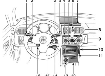
Controls
1. Air intake selector 2. Air flow selector 3. “A/C” button 4. Fan speed selector 5. Temperature selector
SB18008b
114
2005 MR2 from Aug. ’04Prod. (OM17527U)
04 09.01
Fan speed selector Turn the knob to adjust the fan speed—to the right to increase, to the left to de- crease. Temperature selector Turn the knob to adjust the temperature— to the right to warm, to the left to cool.
G18021
Air flow selector Turn the knob to select the vents used for air flow. 1. Panel—Air
flows mainly
the in-
from
strument panel vents.
2. Bi−level—Air flows from both the floor vents and the instrument panel vents. 3. Floor—Air flows mainly from the floor
vents.
the
4. Floor/Windshield—Air
flows mainly floor vents and windshield
from vents. Use with the air intake selector posi- tioned in Fresh.
5. Windshield—Air flows mainly from the
windshield vents. Use with the air intake selector posi- tioned in Fresh.
For details about air flow selector settings, see “Air flow selector settings” described below. Turning the air flow control knob to wind- shield or floor/windshield position turns on the defroster−linked air conditioning. At this time, the “A/C” button indicator comes on regardless of whether or not the “A/C” button is pressed in. This is to clean up the front view more quickly. When the “A/C” button is not pressed in, turning the air flow control knob to anoth- er position turns off the air conditioning.
2005 MR2 from Aug. ’04Prod. (OM17527U)
115
04 09.01
G18023
“A/C” button To turn on the air conditioning, press the “A/C” button. The “A/C” button indicator will come on. To turn the air conditioning off, press the button again. If the “A/C” button indicator flashes, there is a problem in the air conditioning system and the air conditioning automatically shuts off. If this happens, take your ve- hicle to a Toyota dealer for service.
Air intake selector Move the lever to select the air source. 1. Recirculate—Recirculates the air inside
the vehicle.
2. Fresh—Draws outside air into the sys-
tem.
116
2005 MR2 from Aug. ’04Prod. (OM17527U)
04 09.01
Air flow selector settings
SB18009
Operating tips D To cool off your Toyota after
it has been parked in the hot sun, drive with the windows open for a few minutes. This vents the hot air, allowing the air conditioning to cool the interior more quickly.
D Make sure the air intake grilles in front of the windshield are not blocked (by leaves or snow, for example).
D On humid days, do not blow cold air on the windshield. The windshield could fog up because of the difference in air temperature on the inside and outside of the windshield.
D Keep the area under the seats clear to allow air to circulate throughout the ve- hicle.
D On cold days, set the fan speed to “high” for a minute to help clear the intake ducts of snow or moisture. This can reduce the amount of fogging on the windows.
D When driving on dusty roads, close all windows. If dust thrown up by the ve- hicle is still drawn into the vehicle after closing the windows, it is recommended that the air intake selector be set to FRESH and the fan speed selector to any setting except “OFF”.
2005 MR2 from Aug. ’04Prod. (OM17527U)
117
04 09.01
D If following another vehicle on a dusty road, or driving in windy and dusty conditions, it is recommended that the air intake selector be temporarily set to RECIRCULATE, which will close off the outside passage and prevent outside air and dust from entering the vehicle interior.
Heating For best results, set controls to:
Air conditioning For best results, set controls to:
Fan speed—Any setting except “OFF” Temperature—Towards WARM
Fan speed—Any setting except “OFF” Temperature—Towards COLD
(red zone)
Air intake—FRESH (outside air) Air flow—FLOOR Air conditioning—OFF
(blue zone)
Air intake—FRESH (outside air) Air flow—PANEL Air conditioning—ON
for a
few minutes. To keep
D For quick heating, select recirculated air the windows from fogging. select fresh af- ter interior has been warmed.
the vehicle
D Press the “A/C” button on for dehumidi-
fied heating.
D Choose floor/windshield air flow to heat the vehicle interior while defrosting or defogging the windshield.
D For quick cooling, move the air intake selector to recirculate for a few min- utes.
Ventilation For best results, set controls to:
Fan speed—Any setting except “OFF” Temperature—Towards COLD
(blue zone)
Air intake—FRESH (outside air) Air flow—PANEL Air conditioning—OFF
118
2005 MR2 from Aug. ’04Prod. (OM17527U)
04 09.01
Defogging The inside of the windshield For best results, set controls to:
Defrosting The outside of the windshield For best results, set controls to:
Fan speed—Any setting except “OFF” Temperature—Towards WARM
Fan speed—Any setting except “OFF” Temperature—Towards WARM
(red zone) to heat; COLD (blue zone) to cool
Air intake—FRESH (outside air) Air flow—WINDSHIELD
turns on
Turning the air flow control knob to wind- shield position the defroster− linked air conditioning. At this time, the “A/C” button indicator comes on regard- less of whether or not the “A/C” button is pressed in. This is to clean up the front view more quickly. When the “A/C” button is not pressed in, turning the air flow control knob to a posi- tion other than windshield or floor/wind- shield turns off the air conditioning. D On humid days, do not blow cold air on the windshield—the difference be- tween the outside and inside tempera- tures could make the fogging worse.
(red zone)
Air intake—FRESH (outside air) Air flow—WINDSHIELD
turns on
Turning the air flow control knob to wind- shield position the defroster− linked air conditioning. At this time, the “A/C” button indicator comes on regard- less of whether or not the “A/C” button is pressed in. This is to clean up the front view more quickly. When the “A/C” button is not pressed in, turning the air flow control knob to a posi- tion other than windshield or floor/wind- shield turns off the air conditioning. D To heat the vehicle interior while de- floor/
the windshield, choose
frosting windshield air flow.
Side vents
Open
Close
SB18005a
If air flow control is not satisfactory, check the side vents. The side vents may be opened or closed as shown.
2005 MR2 from Aug. ’04Prod. (OM17527U)
119
04 09.01
120
2005 MR2 from Aug. ’04Prod. (OM17527U)
04 09.01
SECTION 2
INFORMATION BEFORE DRIVING YOUR TOYOTA Information before driving your Toyota Break−in period Fuel Fuel pump shut off system Operation in foreign countries Three−way catalytic converter Engine exhaust cautions Facts about engine oil consumption Iridium−tipped spark plugs Brake system Brake pad wear limit indicators Limited−slip differential Your Toyota’s identification Theft prevention labels Suspension and chassis Tire information Vehicle load limits Cargo and luggage Types of tires
. . . . . . . . . . . . . . . . . . . . . . . . . . . . . . . . . . . . . . . . . . . . . . . . . . . . . . . . . . . . . . . . . . . . . . . . . . . . . . . . . . . . . . . . . . . . . . . . . . . . . . . . . . . . . . . . . . . . . . . . . . . . . . . . . . . . . . . . . . . . . . . . . . . . . . . . . . . . . . . . . . . . . . . . . . . . . . . . . . . . . . . . . . . . . . . . . . . . . . . . . . . . . . . . . . . . . . . . . . . . . . . . . . . . . . . . . . . . . . . . . . . . . . . . . . . . . . . . . . . . . . . . . . . . . . . . . . . . . . . . . . . . . . . . . . . . . . . . . . . . . . . . . . . . . . . . . . . . . . . . . . . . . . . . . . . . . . . . . . . . . . . . . . . . . . . . . . . . . . . . . . . . . . . . . . . . . . . . . . . . . . . . . . . . . . . . . . . . . . . . . . . . . . . . . . . . . . . . . . . . . . . . . . . . . . . . . . . . . . . . . . . . . . . . . . . . . . . . . . . . . . . . . . . . . . . . . . . . . . . . . . . . . . . . . . . . . . . . . . . . . . . . . . . . . . . . . . . . . . . . . . . . . . . . . . . . . . . . . . . . . . . . . . . . . . . . . . . . . . . . . . . . . . . . . . . . . . . . . . . . . . . . . . . . . . . . . . . . . . . . . . . . . . . . . . . . . . . . . . . . . . . . . . . . . . . . . . . . . . . . . . . . . . . . . . . . . . . . . . . . . . . . . . . . . . . . . . . . . . . . . . . . . . . . . . . .
130
130
132
132
132
133
134
135
135
138
139
139
140
140
141
149
149
1522005 MR2 from Aug. ’04Prod. (OM17527U)
129
04 09.01
Break−in period Drive gently and avoid high speeds. Your vehicle does not need an elaborate break−in. But following a few simple tips for the first 1600 km (1000 miles) can add to the future economy and long life of your vehicle: D Avoid full
throttle acceleration when
starting and driving.
D Avoid racing the engine. D Try to avoid hard stops during the first
300 km (200 miles).
D Do not drive slowly with the transmis-
sion in a high gear.
D Do not drive for a long time at any
single speed, either fast or slow.
Fuel FUEL TYPE Your new vehicle must use only unleaded gasoline. To help prevent gas station mix−ups, your Toyota has a smaller fuel tank opening. The special nozzle on pumps with un- leaded fuel will fit it, but the larger stan- dard nozzle on pumps with leaded gas will not. At a minimum, should meet D4814 in the U.S.A.
the gasoline you use specifications of ASTM
NOTICE
Do not use leaded gasoline. Use of leaded gasoline will cause the three− way catalytic converter to lose its ef- fectiveness and the emission control system to function improperly. Also, this can increase maintenance costs.
OCTANE RATING Select Octane Rating 87 (Research Oc- tane Number 91) or higher. Use of unleaded fuel with an octane num- ber or rating lower than stated above will cause persistent heavy knocking. If se- vere, this will lead to engine damage.
fuel, or
the recommended
If your engine knocks... If you detect heavy knocking even when using if you hear steady knocking while holding a steady speed on level roads, consult your Toyota dealer. However, occasionally, you may notice light knocking for a short time while accel- erating or driving up hills. This is normal and there is no need for concern. GASOLINES CONTAINING DETERGENT ADDITIVES Toyota recommends the use of gaso- lines that contain detergent additives to avoid build−up of engine deposits. However, all gasoline sold in the U.S con- tains detergent additives to keep clean and/or clean intake systems.
130
2005 MR2 from Aug. ’04Prod. (OM17527U)
04 09.01
for quality
QUALITY GASOLINE Automotive manufacturers in the U.S., Europe and Japan have developed a specification fuel named World−Wide Fuel Charter (WWFC) that is expected to be applied world wide. The WWFC consists of four categories that depend on required emission lev- els. In the U.S., category 3 has been adopted. The WWFC improves air quali- ty by providing for better emissions in vehicle fleets, and customer satisfaction through better vehicle performance. CLEANER BURNING GASOLINE Cleaner burning gasoline, including re- formulated gasoline that contains oxy- genates such as ethanol or MTBE is available in many areas. Toyota recommends the use of cleaner burning gasoline and appropriately blended reformulated gasoline. These types of gas- oline provide excellent vehicle perfor- mance, reduce vehicle emissions, and im- prove air quality.
If you use gasohol
OXYGENATES IN GASOLINE Toyota allows the use of oxygenate blended gasoline where the oxygenate content is up to 10% ethanol or 15% MTBE. in your Toyota, be sure that it has an octane rating no lower than 87. Toyota does not recommend the use of gasoline containing methanol. GASOLINE CONTAINING MMT Some gasoline contain an octane en- hancing additive called MMT (Methylcy- cropentadienyl Manganese Tricarbonyl). Toyota does not recommend the use of gasoline that contains MMT. If fuel con- taining MMT is used, your emission con- trol system may be adversely affected. The Malfunction Indicator Lamp on the in- strument cluster may come on. If this happens, contact your Toyota dealer for service. GASOLINE QUALITY In a very few cases, you may experience driveability problems caused by the partic- ular gasoline that you are using. If you continue to have unacceptable driveability, try changing gasoline brands. If this does not rectify your problem, then consult your Toyota dealer.
NOTICE
z Do not use gasohol other
than stated above. It will cause fuel sys- tem damage or vehicle performance problems.
z If driveability problems occur (poor engine
hot knock, etc.), discontinue the use.
vaporizing,
starting,
z Take care not to spill gasohol dur- ing refueling. Gasohol may cause paint damage.
FUEL TANK CAPACITY
48 L (12.7 gal., 10.6 Imp. gal.)
2005 MR2 from Aug. ’04Prod. (OM17527U)
131
04 09.01
Fuel pump shut off system The fuel pump shut off system stops sup- plying fuel to the engine to minimize the risk of fuel leakage when the engine stalls or an airbag inflates upon collision. To restart the engine after the fuel pump shut off system activates, ignition switch to “ACC” or “LOCK” once and start it.
turn
the
CAUTION
Inspect the ground under the vehicle before restarting the engine. If you find that liquid has leaked onto the ground, fuel system has been damaged and it is in need of repair. In this case, do not restart the engine.
the
is
it
Operation in foreign countries If you plan to drive your Toyota another country... First, comply with the vehicle registration laws. Second, confirm the availability of the cor- rect fuel (unleaded and minimum octane number).
in
Three−way catalytic converter
SB21013a
The three−way catalytic converter is an emission control device installed in the exhaust system. Its purpose is to reduce pollutants in the exhaust gas.
CAUTION
D Keep people and combustible mate- rials away from the exhaust pipe while the engine is running. The exhaust gas is very hot.
D Do not drive, idle or park your ve- hicle over anything that might burn easily such as grass, leaves, paper or rags.
132
2005 MR2 from Aug. ’04Prod. (OM17527U)
04 09.01
NOTICE
large amount of unburned gases into the three−way catalytic flowing converter may cause it to overheat and create a fire hazard. To prevent this and other damage, observe the following precautions: z Use only unleaded gasoline. z Do not drive with an extremely low fuel level; running out of fuel could cause the engine to misfire, creat- ing an excessive load on the three− way catalytic converter.
z Do not allow the engine to run at idle speed for more than 20 min- utes.
z Avoid racing the engine. z Do not push−start or pull−start your
vehicle.
z Do not turn off the ignition while
the vehicle is moving.
in
z Keep your engine in good running order. Malfunctions the engine electrical system, electronic ignition system/distributor ignition system or fuel system could cause an ex- tremely high three−way catalytic converter temperature.
z If the engine becomes difficult to start or stalls frequently, take your vehicle in for a check−up as soon as possible. Remember, your Toyota dealer knows your vehicle and its three−way catalytic converter sys- tem best.
z To ensure that the three−way cata- lytic converter and the entire emis- sion control system operate proper- ly, your vehicle must receive the periodic inspections required by the Toyota Maintenance Schedule. For scheduled maintenance information, refer to the “Scheduled Maintenance Guide” or Manual Supplement”.
“Owner’s
Engine exhaust cautions
CAUTION
D Avoid inhaling the engine exhaust. It contains carbon monoxide, which is a colorless and odorless gas. It can cause unconsciousness or even death.
D Make sure the exhaust system has no holes or loose connections. The system should be checked from time to time. If you hit something, or notice a change in the sound of the the system exhaust, have checked immediately.
D Do not run the engine in a garage or enclosed area except the time needed to drive the vehicle in or out. The exhaust gases cannot escape, making this a particularly dangerous situation.
for
D Do not remain for a long time in a parked vehicle with the engine run- ning. If it is unavoidable, however, do so only in an unconfined area and adjust the heating or cooling system to force outside air into the vehicle.
2005 MR2 from Aug. ’04Prod. (OM17527U)
133
04 09.01
D To allow proper operation of your vehicle’s ventilation system, keep the inlet grilles in front of the wind- shield clear of snow, leaves, or oth- er obstructions.
D If you smell exhaust fumes in the the windows vehicle, drive with open. Have the cause immediately located and corrected.
Facts about engine oil consumption FUNCTIONS OF ENGINE OIL Engine oil has the primary functions of lubricating and cooling the inside of the engine, and plays a major role in main- taining the engine in proper working order. ENGINE OIL CONSUMPTION It is normal that an engine should con- sume some engine oil during normal engine operation. The causes of oil consumption in a normal engine are as follows. D Oil is used to lubricate pistons, piston rings and cylinders. A thin film of oil is left on the cylinder wall when a pis- ton moves downwards in the cylinder. High negative pressure generated when the vehicle is decelerating sucks some of this oil into the combustion chamber. This oil as well as some part of the oil film left on the cylinder wall is burned by temperature combustion gases during the combustion process. D Oil is also used to lubricate the stems of the intake valves. Some of this oil is sucked into the combustion chamber together with is burned along with the fuel. High tem- perature exhaust gases also burn the oil used to lubricate the exhaust valve stems.
intake air and
the high
the
The amount of engine oil consumed de- pends on the viscosity of the oil, the quality of the oil and the conditions the vehicle is driven under. More oil is consumed by high−speed driv- ing and frequent acceleration and decel- eration. A new engine consumes more oil, since its pistons, piston rings and cylinder walls have not become conditioned. Oil consumption: Max. 1.0 L per 1000
km (1.1 qts./600 miles, 0.9 lmp.qts./600
miles) When judging the amount of oil con- sumption, note that the oil may become diluted and make it difficult to judge the true level accurately. As an example, if a vehicle is used for repeated short trips, and consumes a nor- mal amount of oil, the dipstick may not show any drop in the oil level at all, even after 1000 km (600 miles) or more. This is because the oil is gradually becoming diluted with fuel or moisture, making it appear that the oil level has not changed. The diluting ingredients evaporate out when the vehicle is then driven at high speeds, as on an expressway, making it appear that oil is excessively consumed after driving at high speeds.134
2005 MR2 from Aug. ’04Prod. (OM17527U)
04 09.01
IMPORTANCE OF ENGINE OIL LEVEL CHECK One of the most important points in prop- er vehicle maintenance is to keep the en- gine oil at the optimum level so that oil function will not be impaired. Therefore, it is essential that the oil level be checked regularly. Toyota recommends that the oil level be checked every time you refuel the vehicle.
NOTICE
Failure to check the oil level regularly could lead to serious engine trouble due to insufficient oil.
For detailed information on oil level check, see “Checking level” on page 208 in Section 7−2.
the engine oil
Iridium−tipped spark plugs
SB21011
Your engine is fitted with iridium−tipped spark plugs.
NOTICE
Use only iridium−tipped spark plugs and do not adjust gaps for your en- gine performance and smooth drive- ability.
Brake system The tandem master cylinder brake system is a hydraulic system with two separate sub−systems. If either sub−system should fail, the other will still work. However, the pedal will be harder to press, and your stopping distance will increase. Also, the brake system warning light may come on.
CAUTION
Do not drive your vehicle with only a single brake system. Have your brakes fixed immediately.
BRAKE BOOSTER The brake booster uses engine vacuum to power−assist the engine should quit while you are driving, you can bring the vehicle to a stop with normal pedal pressure. There is enough reserved vacuum for one or two stops but no more!
the brakes.
If
2005 MR2 from Aug. ’04Prod. (OM17527U)
135
04 09.01
CAUTION
D Do not pump the brake pedal if the engine stalls. Each push on the pedal uses up your reserved vacu- um.
lost,
D Even if the power assist
is com- pletely the brakes will still work. But you will have to push the pedal hard, much harder than nor- mal. And your braking distance will increase.
ANTI−LOCK BRAKE SYSTEM The anti−lock brake system is designed to automatically help prevent lock−up of the wheels during a sudden braking or braking on slippery road surfaces. This assists in providing directional stability and steering performance of the vehicle under these circumstances.
the
brake
anti−lock
Effective way to press the ABS brake pedal: system When function is in action, you may feel the brake pedal pulsating and hear a noise. In the anti−lock brake system work for you, just hold the brake pedal down more firmly. Do not pump the brake in a panic stop. This will result braking performance.
this situation,
reduced
let
to
in
The anti−lock brake system becomes op- erative after the vehicle has accelerated to a speed in excess of approximately 10
km/h (6 mph). It stops operating when the vehicle decelerates to a speed below approximately 5 km/h (3 mph). Depressing the brake pedal on slippery road surfaces such as on a manhole cov- er, a steel plate at a construction site, joints in a bridge, etc. on a rainy day tends to activate the anti−lock brake sys- tem. You may hear a click or motor sound in the front trunk room for a few seconds when the engine is started or just after the vehicle begins to move. This means that the anti−lock brake system is in the self check mode, and does not indicate a malfunction.When the anti−lock brake system is ac- tivated, the following conditions may occur. They do not indicate a malfunc- tion of the system: D You may hear the anti−lock brake sys- tem operating and feel the brake pedal pulsating and the vibrations of the ve- hicle body and steering wheel. You may also hear the motor sound in the front trunk room even after the vehicle is stopped.
D At the end of the anti−lock brake sys- the brake pedal may
tem activation, move a little forward.
CAUTION
Do not overestimate the anti−lock brake system: Although the anti−lock brake system assists in providing ve- hicle control, it is still important to drive with all due care and maintain a moderate speed and safe distance from the vehicle in front of you, be- cause there are limits to the vehicle stability and effectiveness of steering wheel operation even with the anti− lock brake system on.
136
2005 MR2 from Aug. ’04Prod. (OM17527U)
04 09.01
If tire grip performance exceeds its capability, or if hydroplaning occurs during high speed driving in the rain, the anti−lock brake system does not provide vehicle control. Anti−lock brake system is not de- signed to shorten the stopping dis- tance: Always drive at a moderate speed and maintain a safe distance from front of you. Compared with vehicles without an anti−lock brake system, your vehicle may require a longer stopping dis- tance in the following cases: D Driving on rough, gravel or snow−
the vehicle
in
covered roads.
D Driving with tire chains installed. D Driving over the steps such as the
joints on the road.
D Driving on roads where the road surface is pitted or has other differ- ences in surface height.
Install all 4 tires of specified size at appropriate pressure: The anti−lock brake system detects vehicle speeds using the speed sensors for respec- tive wheels’ turning speeds. The use of tires other than specified may fail to detect the accurate turning speed resulting longer stopping dis- tance.
in a
SD02002a
“ABS” warning light The light comes on when the ignition key is turned to the “ON” position. If the anti− lock brake system works properly, the light turns off after a few seconds. There- after, if the system malfunctions, the light comes on again. When the “ABS” warning light is on (and the brake system warning light is off), the anti−lock brake system does not operate, but the brake system still operates con- ventionally.
2005 MR2 from Aug. ’04Prod. (OM17527U)
137
04 09.01
CAUTION
If the “ABS” warning light remains on together with the brake system warn- ing light, immediately stop your ve- hicle at a safe place and contact your Toyota dealer. In this case, not only the anti−lock brake system will fail but also the vehicle will become extremely unsta- ble during braking.
When the “ABS” warning light is on (and the brake system warning light is off), the anti−lock brake system does not operate so that the wheels could lock up during a sudden braking or braking on slippery road surfaces. If either of the following conditions oc- cur, this indicates a malfunction some- where in the components monitored by the warning light system. Contact your Toyota dealer as soon as possible to service the vehicle. D The light does not come on when the ignition key is turned to the “ON” posi- tion, or remains on.
D The light comes on while you are driv-
ing.
A warning light turning on briefly during operation does not indicate a problem.
Brake pad wear limit indicators
SB21015
The brake pad wear limit indicators on your disc brakes give a warning noise when the brake pads are worn to where replacement is required. If you hear a squealing or scraping noise while driving, have the brake pads checked and replaced by your Toyota dealer as soon as possible. Expensive ro- tor damage can result if the pads are not replaced when necessary.
138
2005 MR2 from Aug. ’04Prod. (OM17527U)
04 09.01
Limited−slip differential (on some models) Some Toyotas are equipped with a limit- ed−slip differential. rear wheels begins to spin, the limited−slip dif- ferential traction by automatically transmitting driving force to the other rear wheel. If you are not sure whether your vehicle is equipped with one, you can ask your Toyota dealer.
is designed
If one of
to aid
the
CAUTION
Do not start or run the engine while your vehicle is supported by a jack. The vehicle could be driven off the jack and could pose a danger or re- sult in serious injury.
NOTICE
Use only a compact spare tire of the same size, construction and load ca- pacity as the original tires on your Toyota because damage to the limit- ed−slip differential could possibly oc- cur with another tire type.
Your Toyota’s identification— —Vehicle identification number
SB21009
SB21024
The vehicle identification number (VIN) is the legal identifier for your vehicle. This number is on the left top of the instrument panel, and can be seen through the windshield from outside. This is the primary identification number for your Toyota. It is used in registering the ownership of your vehicle.
The vehicle identification number (VIN) is also on the Certification Label.
2005 MR2 from Aug. ’04Prod. (OM17527U)
139
04 09.01
—Engine number
SB21010
The engine number is stamped on the engine block as shown.
Suspension and chassis
CAUTION
Do not modify the suspension/chassis with lift kits, spacers, springs, etc. It can cause dangerous handling charac- teristics, resulting in loss of control.
Theft prevention labels Your new vehicle carries theft preven- tion labels which are approximately 47
mm (1.85 in.) by 12 mm (0.47 in.). The purpose of these labels is to reduce the incidence of vehicle thefts by facilitat- ing the tracing and recovery of parts from stolen vehicles. The label is designed so that once it is applied to a surface, any attempt to remove it will result in destroy- ing the integrity of the label. Transferring these labels intact from one part to anoth- er, will be impossible.NOTICE
You should not attempt to remove the theft prevention labels as it may vio- late certain state or federal laws.
140
2005 MR2 from Aug. ’04Prod. (OM17527U)
04 09.01
Tire information— —Tire symbols
SB21020c
This illustration indicates typical tire symbols. 1. Tire size—For details, see “Tire
size” on page 143.
2. DOT and Tire
Identification Number (TIN)—For details, see “DOT and Tire Identification Num- ber (TIN)” on page 142.
3. Maximum cold
tire
inflation pressure—This means the pres- sure to which a tire may be in- flated. For recommended cold tire inflation pressure, see “Tires” on page 244.
4. Load limit at maximum cold tire inflation pressure—For details, see “Checking and replacing tires” on page 215.
5. Location of tread wear indica- tors—For details, see “Checking and replacing tires” on page 215. indicator—Some vehicles are equipped with directional tires. For details, see “Rotating tires” on page 218.
6. Turning
2005 MR2 from Aug. ’04Prod. (OM17527U)
141
04 09.01
7. Uniform tire quality grading— For details, see “Uniform tire quali- ty grading” that follows.
8. Tire ply composition and mate- rials—Plies mean a layer of rub- ber−coated parallel cords. Cords mean the strands forming the plies in the tire.
—DOT and Tire Identification Number (TIN)
SB21022a
The “DOT” symbol certifies that the tire conforms to applicable Federal Motor Vehicle Safety Standards.
9. “TUBELESS”
or
“TUBE TYPE”—A tubeless tire does not have a tube inside the tire and air is directly filled in the tire. A tube type tire has a tube inside the tire and the tube maintains the air pressure.
10.Radial tires or bias−ply tires—A radial tire has “RADIAL” on the sidewall. A tire not marked with “RADIAL” is a bias−ply tire.
11. Summer
the sidewall. The
tire or all season tire—An all season tire has “M+S” on tire not marked with “M+S” is a summer tire. For details, see “Types of tires” on page 152.
This illustration indicates typical DOT and Tire Identification Number (TIN). 1. “DOT” symbol 2. Tire Identification Number (TIN) 3. Tire manufacturer’s identification
mark
4. Tire size code 5. Manufacturer’s optional tire type
code
6. Manufacturing week 7. Manufacturing year
142
2005 MR2 from Aug. ’04Prod. (OM17527U)
04 09.01
—Tire size
—Name of each section of tire
SB21021a
SU21026a
SU21027
1. Section width 2. Tire height 3. Wheel diameter
This illustration indicates typical tire size. 1. Section width (in millimeters) 2. Aspect ratio (tire height to section
width)
3. Tire construction code (R=Radial,
D=Diagonal)
4. Wheel diameter (in inches) 5. Load index (2 digits or 3 digits) 6. Speed symbol (alphabet with one
letter)
1. Bead 2. Sidewall 3. Shoulder 4. Tread 5. Belt 6. Inner liner 7. Reinforcing rubber 8. Carcass 9. Rim lines 10.Bead wires 11. Chafer
2005 MR2 from Aug. ’04Prod. (OM17527U)
143
04 09.01
—Uniform tire quality grading This information has been prepared in accordance with regulations issued by the National Highway Traffic Safe- ty Administration of the U.S. Depart- ment of Transportation. It provides the purchasers and/or prospective purchasers of Toyota vehicles with in- formation on uniform tire quality grad- ing. Your Toyota dealer will help answer any questions you may have as you read this information. DOT quality grades—All passenger vehicle tires must conform to Fed- eral Safety Requirements in addi- tion these grades. Quality grades can be found where appli- cable on the tire sidewall between tread shoulder and maximum sec- tion width. For example: Treadwear 200 Traction AA Temperature A.
to
Treadwear—The tread wear grade is a comparative rating based on the wear rate of the tire when tested un- der controlled conditions on a speci- fied government test course. For ex- ample, a tire graded 150 would wear one and a half (1−1/2) times as well on the government course as a tire graded 100. The relative performance of tires depends upon the actual con- ditions of their use, however, and may depart significantly from the norm due to variations in driving habits, service practices and differences in road characteristics and climate. Traction AA, A, B, C—The traction grades, from highest to lowest, are AA, A, B, and C, and they represent the tire’s ability to stop on wet pave- ment as measured under controlled conditions on specified government test surfaces of asphalt and concrete. A tire marked C may have poor trac- tion performance.
this
Warning: The traction grade assigned to tire is based on braking (straight ahead) traction tests and does not include cornering (turning) traction. Temperature A, B, C—The tempera- ture grades are A (the highest), B, and C, representing the tire’s resist- ance to the generation of heat and its ability to dissipate heat when tested under controlled conditions on a spe- cified indoor laboratory test wheel. Sustained high temperature can cause the material of the tire to de- generate and reduce tire life, and ex- cessive temperature can lead to sud- den failure. The grade C corresponds to a level of performance which all passenger car tires must meet under the Federal Motor Vehicle Safety Standard No.109. Grades B and A represent higher levels of per- formance on the laboratory test wheel than the minimum required by law.
tire
144
2005 MR2 from Aug. ’04Prod. (OM17527U)
04 09.01
Warning: The temperature grades for this tire are established for a tire that is properly inflated and not over- loaded. Excessive speed, underinfla- tion, or excessive loading, either sep- arately or in combination, can cause heat buildup and possible tire failure.
2005 MR2 from Aug. ’04Prod. (OM17527U)
145
04 09.01
—Glossary of tire terminology
Tire related term
Cold tire inflation pressure
Maximum inflation pressure
Recommended inflation pressure
Accessory weight
Curb weight
Maximum loaded vehicle weight
Meaning
tire inflation pressure when the vehicle has been parked for at least 3 hours or more, or it has not been driven more than 1.5 km or 1 mile under that condition the maximum cold inflation pressure to which a tire may be inflated and it is shown on the sidewall of the tire cold tire inflation pressure recommended by a manufacturer the combined weight (in excess of those standard items which may be replaced) of automatic transmission, power steering, power brakes, power windows, pow- er seats, radio, and heater, to the extent that these items are available as factory−installed equipment (whether installed or not) the weight of a motor vehicle with standard equipment including the maximum capacity of fuel, oil, and coolant, and, if so equipped, air conditioning and addi- tional weight optional engine
the sum of— (a) curb weight; (b) accessory weight; (c) vehicle capacity weight; and (d) production options weight
Normal occupant weight
68 kg (150 lb.) times the number of occupants specified in the second column of Table 1 that follows
146
2005 MR2 from Aug. ’04Prod. (OM17527U)
04 09.01
Tire related term
Meaning
Production options weight
Vehicle capacity weight (Total load capacity)
Intended outboard sidewall
Occupant distribution
Rim
Rim diameter (Wheel diameter) Rim size designation Rim type designation Rim width
Vehicle maximum load on the tire
the combined weight of those installed regular production options weighing over 2.3 kg (5 lb.) in excess of those standard items which they replace, not pre- viously considered in curb weight or accessory weight, including heavy duty brakes, ride levelers, roof rack, heavy duty battery, and special trim the rated cargo and luggage load plus 68 kg (150 lb.) times the vehicle’s desig- nated seating capacity (A) the sidewall that contains a whitewall, bears white lettering or bears manufacturer, brand, and/or model name molding that is higher or deeper than the same molding on the other sidewall of the tire, or
(B) the outward facing sidewall of an asymmetrical tire that has a particular
side that must always face outward when mounted on a vehicle
distribution of occupants in a vehicle as specified in the third column of Table 1 that follows a metal support for a tire or a tire and tube assembly upon which the tire beads are seated nominal diameter of the bead seat rim diameter and width the industry of manufacturer’s designation for a rim by style or code nominal distance between rim flanges the load on an individual tire that is determined by distributing to each axle its share of the maximum loaded vehicle weight and dividing by two
2005 MR2 from Aug. ’04Prod. (OM17527U)
147
04 09.01
Tire related term
Meaning
Vehicle normal load on the tire
Weather side
the load on an individual tire that is determined by distributing to each axle its share of the curb weight, accessory weight, and normal occupant weight (distributed in accordance with Table 1 that follows) and dividing by two the surface area of the rim not covered by the inflated tire
Table 1–Occupant loading and distribution for vehicle normal load for various designated seating capacities
Designated seating capacity, number of occupants 2 through 4
5 through 10Vehicle normal load, number of occu- pants
Occupant distribution in a normally loaded vehicle 2 in front 2 in front, 1 in second seat
148
2005 MR2 from Aug. ’04Prod. (OM17527U)
04 09.01
Vehicle load limits Vehicle load limits include total load capacity, seating capacity, towing ca- pacity and cargo capacity. Follow the load limits shown below. Total load capacity:
193 kg (425 lb.)
Total load capacity means combined weight of occupants, cargo and lug- gage. Tongue load is included when trailer towing. Seating capacity: Total 2 (Front 2)
Seating capacity means the maximum number of occupants whose esti- mated average weight is 68 kg (150
lb.) per person. Depending on the weight of each person, the seating ca- pacity given may exceed the total load capacity.NOTICE
Even if the number of occupants are within the seating capacity, do not exceed the total load ca- pacity.
Towing capacity Toyota does not recommend towing a trailer with your vehicle. Your ve- hicle is not designed for trailer towing. Cargo capacity Cargo capacity may increase or de- crease depending on the size (weight) and the number of occupants. For de- tails, see “Capacity and distribution” that follows.
CAUTION
Do not apply the load more than each load limit. That may cause not only damage to the tires, but also deterioration to the steering ability and braking ability, which may cause an accident.
Cargo and luggage— —Stowage precautions When stowing cargo and luggage in the vehicle, observe the following: D Put cargo and luggage in the front box or luggage space when at all possible. Be sure all items are se- cured in place.
D Be careful to keep the vehicle bal- anced. Locating the weight as far forward as possible helps maintain balance.
D For better fuel economy, do not
carry unneeded weight.
CAUTION
D Never allow anyone to ride in the luggage space. It is not de- signed for the passenger. The passenger should ride in the seat with the seat belt properly fastened. Severe injuries to an unrestrained passenger can occur during sudden braking or a collision.
2005 MR2 from Aug. ’04Prod. (OM17527U)
149
04 09.01
D Do not drive with objects left on top of the instrument panel. They may interfere with the driver’s field of view. Or they may move during sharp vehicle acceleration or turning, and im- pair the driver’s control of the vehicle. In an accident they may injure the vehicle occu- pants.
FOR
—Capacity and distribution Cargo capacity depends on the to- tal weight of the occupants. (Cargo capacity) = (Total load capac- ity) – (Total weight of occupants) STEPS CORRECT LOAD LIMIT 1. Locate
“The combined weight of occupants and cargo should never exceed XXX pounds” on your vehicle’s placard. 2. Determine the combined weight of the driver and passengers that will be riding in your vehicle.
DETERMINING
statement
the
3. Subtract the combined weight of the driver and passengers from XXX kilograms or XXX pounds.
4. The resulting figure equals the available amount of cargo and lug- gage load capacity. For example, if the “XXX” amount equals 1400
lbs. and there will be five 150 lb. passengers in your vehicle, the amount of available cargo and lug- gage load capacity is 650 lbs. (1400–750 (5x150)=650 lbs).5. Determine the combined weight of luggage and cargo being loaded on the vehicle. That weight may not safely exceed the available cargo and luggage load capacity calculated in Step 4.
6. If your vehicle will be towing a trailer, load from your trailer will be transferred to your vehicle. Consult this manual to determine how this reduces the available car- go and luggage load capacity of your vehicle.
Toyota does not recommend towing a trailer with your vehicle. Your ve- hicle is not designed for trailer towing.
150
2005 MR2 from Aug. ’04Prod. (OM17527U)
04 09.01
SB21023
Cargo capacity
Total load capacity
EXAMPLE ON YOUR VEHICLE In case that 1 people with the com- bined weight of 80 kg (176 lb.) are riding in your vehicle with the total load capacity of 193 kg (425 lb.), the available amount of cargo and lug- gage load capacity will be as follows: 193 kg – 80 kg = 113 kg. (425 lb. – 176 lb. = 249 lb.) From this condition, if 1 more passen- ger with the combined weight of 70
kg (154 lb.) get on, the available car- go and luggage load will be reduced as follows:113 kg – 70 kg = 43 kg. (249 lb. – 154 lb. = 95 lb.) As shown in the above example, if the number of occupants increases, the cargo and luggage load equaling the combined weight of occupants who got on later must be reduced. In other words, if the increase in the number of occupants causes the excess of the total load capacity (combined weight of occupants plus cargo and luggage load), you have to reduce the cargo and luggage on your vehicle. For details about total load capacity, see “Vehicle load limits” on page 149.
CAUTION
Even if the total load of occu- pant’s weight and the cargo load is less than the total load capac- ity, do not apply the load uneven- ly. That may cause not only dam- age to the tire but also deteriora- tion to the steering ability due to unbalance of the vehicle, causing an accident.
2005 MR2 from Aug. ’04Prod. (OM17527U)
151
04 09.01
Types of tires Determine what kind of tires your vehicle is originally equipped with. 1. Summer tires Summer tires are high−speed capabil- ity tires best suited to highway driving under dry conditions. Since summer tires do not have the same traction performance as snow tires, summer tires are inadequate for driving on snow−covered or icy roads. For driving on snow−covered or icy roads, we recommend using snow tires. If installing snow tires, be sure to replace all four tires. 2. All season tires All season tires are designed to pro- vide better traction in snow and to be adequate for driving in most winter conditions, as well as for use all year round.
CAUTION
D Do not mix summer and all sea- son tires on your vehicle as this can cause dangerous han- dling characteristics, resulting in loss of control.
D Do not use tires other than the manufacture’s designated tires, and never mix tires or wheels of the sizes different from the originals as this can cause dangerous handling characteristics, resulting in loss of control.
152
2005 MR2 from Aug. ’04Prod. (OM17527U)
04 09.01
SECTION 3
STARTING AND DRIVING Starting and driving Before starting the engine How to start the engine Tips for driving in various conditions Winter driving tips Dinghy towing Trailer towing How to save fuel and make your vehicle last longer, too
. . . . . . . . . . . . . . . . . . . . . . . . . . . . . . . . . . . . . . . . . . . . . . . . . . . . . . . . . . . . . . . . . . . . . . . . . . . . . . . . . . . . . . . . . . . . . . . . . . . . . . . . . . . . . . . . . . . . . . . . . . . . . . . . . . . . . . . . . . . . . . . . . . . . . . . . . . . . . . . . . . . . . . . . . . . . . . . . . . . . . . . . . . . . . . . . . . . . . . . . . . . . . . . . . . . . . . . . . . . . . . . . . . . . . . . . . . . . . . . . . .
154
154
155
156
157
158
1582005 MR2 from Aug. ’04Prod. (OM17527U)
153
04 09.01
Before starting the engine 1. Check the area around the vehicle be-
fore entering it.
from
transmission only: Sequential manual When the driver’s door is opened, a motor sound may be heard the engine compartment, but it is not a malfunction. The motor will stop after a certain period of time. 2. Adjust seat position, seatback angle, seat cushion angle and steering wheel angle.
3. Adjust the inside and outside rear view
mirrors.
4. Lock both the doors. 5. Fasten seat belts.
How to start the engine— (a) Before cranking 1. Apply the parking brake firmly. 2. Turn off unnecessary lights and acces-
sories.
ignition switch
from operating if
3. Sequential manual transmission: Turn the to “ON” position. Hold down the brake pedal firmly, and place the selector lever to the “N” posi- tion. Make sure that the “N” indicator in the instrument cluster comes on. A starter safety device will prevent the starter the selector lever is in a position except “N” or the brake pedal is not depressed. Manual transmission: Press the clutch pedal to the floor and shift the trans- mission the clutch pedal to the floor until the engine is started. A starter safety device will pre- vent the starter from operating if the clutch pedal is not fully depressed.
into neutral. Hold
in
the
instructions
the engine, be sure
to “(a) Before
(b) Starting the engine Before starting follow cranking”. Normal starting procedure The multiport fuel injection system/sequen- tial multiport fuel injection system in your engine automatically controls the proper air−fuel mixture for starting. You can start a cold or hot engine as follows:
Sequential manual transmission: With your foot off the accelerator pedal, turn the ignition key to the ”START” position and crank the engine while depressing the brake pedal. Release the key when the engine starts. The engine cannot be cranked if the selector lever is in a position except ”N” or is not de- pressed. Manual transmission: With your foot off the accelerator pedal, crank the en- gine by turning the key to the “START” position. Release the key when the en- gine starts.
the brake pedal
Engine should be warmed up by driving, not in idle. For warming up drive with smoothly turning engine until engine cool- ant temperature is within normal range.
154
2005 MR2 from Aug. ’04Prod. (OM17527U)
04 09.01
If the engine stalls... Simply restart it, using the correct proce- dure given in normal starting. If the engine will not start... See “If your vehicle will not start—” on page 162 in Section 4.
NOTICE
z Do not crank for more than 30 sec- onds at a time. This may overheat the starter and wiring systems.
z Do not race a cold engine. z If the engine becomes difficult to start or stalls frequently, have the engine checked immediately.
Tips for driving in various conditions D Always slow down in gusty crosswinds. This will allow you much better control. D Drive slowly onto curbs and, if pos- sible, at a right angle. Avoid driving onto high, sharp−edged objects and other road hazards. Failure to do so can lead to severe tire damage such as a tire burst. Drive slowly when passing over bumps or travelling on a bumpy road. Other- wise, the impact could cause severe damage to the tires and/or wheels.
they
D When parking on a hill, turn the front wheels until touch the curb so that the vehicle will not roll. Apply the parking brake, and place the transmis- sion in “S(1)” or “R” (sequential manual transmission) or reverse (manual If necessary, block the wheels.
transmission).
first or
in
D Washing your vehicle or driving through deep water may get the brakes wet. To see whether they are wet, check that there is no traffic near you, and then press the pedal lightly. If you do not feel a normal braking force, the brakes are probably wet. To dry them, drive the vehicle cautiously while lightly pressing the brake pedal with the park- ing brake applied. If they still do not work safely, pull to the side of the road and call a Toyota dealer for assistance.
CAUTION
D Before driving off, make sure that the parking brake is fully released and reminder light is off.
the parking brake
D Do not
leave your vehicle unat- tended while the engine is running. D Do not rest your foot on the brake pedal while driving. It can cause dangerous overheating, needless wear, and poor fuel economy.
D To drive down a long or steep hill, reduce your speed and downshift. Remember, if you ride the brakes excessively, they may overheat and not work properly.
D Be careful when accelerating, up- shifting, downshifting or braking on a slippery surface. Sudden accelera- tion or engine braking could cause the vehicle to skid or spin.
2005 MR2 from Aug. ’04Prod. (OM17527U)
155
04 09.01
tire dealer
D Do not drive in excess of the speed limit. Even if the legal speed limit permits it, do not drive over 140
km/h (85 mph) unless your vehicle has high−speed capability tires. Driving over 140 km/h (85 mph) may result in tire failure, loss of control and possible injury. Be sure to con- sult a to determine whether the tires on your vehicle are high−speed capability tires or not before driving at such speeds. D Do not continue normal driving when the brakes are wet. If they are wet, your vehicle will require a lon- ger stopping distance, and it may pull to one side when the brakes are applied. Also, the parking brake will not hold the vehicle securely.Winter driving tips Make sure your coolant is properly pro- tected against freezing. Only use “Toyota Super Long Life Coolant” or similar high quality ethylene glycol