- 2009 Toyota Camry HV Owners Manuals
- Toyota Camry HV Owners Manuals
- 2008 Toyota Camry HV Owners Manuals
- Toyota Camry HV Owners Manuals
- 2012 Toyota Camry HV Owners Manuals
- Toyota Camry HV Owners Manuals
- 2010 Toyota Camry HV Owners Manuals
- Toyota Camry HV Owners Manuals
- 2011 Toyota Camry HV Owners Manuals
- Toyota Camry HV Owners Manuals
- 2007 Toyota Camry HV Owners Manuals
- Toyota Camry HV Owners Manuals
- Download PDF Manual
-
6-1. Specifications Tire information
Typical tire symbols Full-size tire
Compact spare tire
Tire size DOT and Tire Identification Number (TIN) Uniform tire quality grading For details, see “Uniform Tire Quality Grading” that follows. Location of treadwear indicators
(→P. 489) (→P. 488)
(→P. 365)
486
6-1. Specifications
Tire ply composition and materials Plies are layers of rubber-coated parallel cords. Cords are the strands which form the plies in a tire. Radial tires or bias-ply tires A radial tire has “RADIAL” on the sidewall. A tire not marked “RADIAL” is a bias-ply tire. TUBELESS or TUBE TYPE A tubeless tire does not have a tube and air is directly put into the tire. A tube type tire has a tube inside the tire and the tube main- tains the air pressure. Load limit at maximum cold tire inflation pressure Maximum cold tire inflation pressure This means the pressure to which a tire may be inflated. Summer tires or all season tires (→P. 369) An all season tire has “M+S” on the sidewall. A tire not marked “M+S” is a summer tire. “TEMPORARY USE ONLY” (→P. 449) A compact spare tire is identified by the phrase “TEMPORARY USE ONLY” molded on its sidewall. This tire is designed for temporary emergency use only.
(→P. 368) (→P. 480)
487
6-1. Specifications
Typical DOT and Tire Identification Number (TIN)
Identification Number
DOT symbol* Tire (TIN) Tire manufacturer's identifica- tion mark Tire size code Manufacturer's optional type code (3 or 4 letters) Manufacturing week Manufacturing year *: The DOT symbol certifies that to applicable Federal Motor Vehicle Safety Standards.
tire conforms
the
tire
488
Tire size
■ Typical tire size information
■ Tire dimensions
6-1. Specifications
The illustration indicates typical tire size.
Tire use (P = Passenger car, T = Temporary use) Section width (millimeters) Aspect ratio (tire height to section width) Tire construction code (R = Radial, D = Diagonal) Wheel diameter (inches) Load index (2 digits or 3 digits) Speed symbol (alphabet with one letter)
Section width Tire height Wheel diameter
489
6-1. Specifications
Tire section names
Bead Sidewall Shoulder Tread Belt Inner liner Reinforcing rubber Carcass Rim lines Bead wires Chafer
Uniform Tire Quality Grading
This information has been prepared in accordance with regulations issued by the National Highway Traffic Safety Administration of the U.S. Department of Transportation. It provides the purchasers and/or prospective purchasers of Toyota vehicles with information on uniform tire quality grading.
Your Toyota dealer will help answer any questions you may have as you read this information.
■ DOT quality grades
All passenger vehicle tires must conform to Federal Safety Requirements in addition to these grades. Quality grades can be found where applicable on the tire sidewall between tread shoulder and maximum section width. For example: Treadwear 200 Traction AA Temperature A
490
6-1. Specifications
■ Treadwear
The treadwear grade is a comparative rating based on the wear rate of the tire when tested under controlled conditions on a speci- fied government test course. For example, a tire graded 150 would wear one and a half (1 - 1/2) times as well on the government course as a tire graded 100. The relative performance of tires depends upon the actual conditions of their use. Performance may differ significantly from the norm due to vari- ations in driving habits, service practices and differences in road charac- teristics and climate.
■ Traction AA, A, B, C
The traction grades, from highest to lowest, are AA, A, B and C, and they represent the tire's ability to stop on wet pavement as measured under controlled conditions on specified government test surfaces of asphalt and concrete. A tire marked C may have poor traction performance. Warning: The traction grade assigned to this tire is based on braking (straight ahead) traction tests and does not include cornering (turn- ing) traction.
■ Temperature A, B, C
The temperature grades are A (the highest), B, and C, represent- ing the tire's resistance to the generation of heat and its ability to dissipate heat when tested under controlled conditions on a speci- fied indoor laboratory test wheel. Sustained high temperature can cause the material of the tire to degenerate and reduce tire life, and excessive temperature can lead to sudden tire failure. Grade C corresponds to a level of performance which all passenger car tires must meet under the Federal Motor Vehicle Safety Standard No. 109. Grades B and A represent higher levels of performance on the labo- ratory test wheel than the minimum required by law.
491
6-1. Specifications
Warning: The temperature grades of a tire assume that it is properly inflated and not overloaded. Excessive speed, underinflation, or excessive loading, either separately or in combination, can cause heat buildup and possible tire failure.
Glossary of tire terminology
Tire related term
Meaning
Cold tire inflation pres- sure
Maximum inflation pressure
Recommended infla- tion pressure
Accessory weight
Curb weight
Maximum loaded vehi- cle weight
Tire pressure when the vehicle has been parked for three hours or more, or has not been driven more than 1 mile or 1.5 km under that condition The maximum cold inflated pressure to which a tire may be inflated, shown on the sidewall of the tire Cold tire inflation pressure recommended by a manufacturer The combined weight (in excess of those stan- dard items which may be replaced) of auto- matic transmission, power steering, power brakes, power windows, power seats, radio and heater, to the extent that these items are available as factory-installed equipment (whether installed or not) The weight of a motor vehicle with standard equipment, including the maximum capacity of fuel, oil and coolant, and if so equipped, air conditioning and additional weight optional engine The sum of: (a) Curb weight (b) Accessory weight (c) Vehicle capacity weight (d) Production options weight
492
6-1. Specifications
Tire related term
Normal occupant weight
Occupant distribution
Production options weight
Rim
Rim diameter (Wheel diameter) Rim size designation
Rim type designation
Rim width Vehicle capacity weight (Total load capacity)
Vehicle maximum load on the tire
Vehicle normal load on the tire
Meaning
150 lb. (68 kg) times the number of occupants specified in the second column of Table 1* that follows Distribution of occupants in a vehicle as speci- fied in the third column of Table 1* below The combined weight of installed regular pro- duction options weighing over 5 lb. (2.3 kg) in excess of the standard items which they replace, not previously considered in curb weight or accessory weight, including heavy duty brakes, ride levelers, roof rack, heavy duty battery, and special trim A metal support for a tire or a tire and tube assembly upon which the tire beads are seated
Nominal diameter of the bead seat
Rim diameter and width The industry manufacturer's designation for a rim by style or code Nominal distance between rim flanges The rated cargo and luggage load plus 150 lb. (68 kg) times the vehicle's designated seating capacity The load on an individual tire that is determined by distributing to each axle its share of the maximum loaded vehicle weight, and dividing by two The load on an individual tire that is determined by distributing to each axle its share of curb weight, accessory weight, and normal occu- pant weight (distributed in accordance with Table 1* below), and dividing by two
493
6-1. Specifications
Tire related term
Weather side
Bead
Bead separation
Bias ply tire
Carcass
Chunking
Cord
Cord separation
Cracking
CT
Extra load tire
Groove
Innerliner
494
Meaning
The surface area of the rim not covered by the inflated tire The part of the tire that is made of steel wires, wrapped or reinforced by ply cords and that is shaped to fit the rim A breakdown of the bond between components in the bead A pneumatic tire in which the ply cords that extend to the beads are laid at alternate angles substantially less than 90 degrees to the cen- terline of the tread The tire structure, except tread and sidewall rubber which, when inflated, bears the load The breaking away of pieces of the tread or sidewall The strands forming the plies in the tire The parting of cords from adjacent rubber com- pounds Any parting within the tread, sidewall, or inner- liner of the tire extending to cord material A pneumatic tire with an inverted flange tire and rim system in which the rim is designed with rim flanges pointed radially inward and the tire is designed to fit on the underside of the rim in a manner that encloses the rim flanges inside the air cavity of the tire A tire designed to operate at higher loads and at higher inflation pressures than the corre- sponding standard tire The space between two adjacent tread ribs The layer(s) forming the inside surface of a tubeless tire that contains the inflating medium within the tire
Tire related term
Innerliner separation
Intended outboard sidewall
Light truck (LT) tire
Load rating
Maximum load rating
Maximum permissible inflation pressure
Measuring rim
Open splice
Outer diameter
Overall width
Passenger car tire
6-1. Specifications
Meaning
The parting of the innerliner from cord material in the carcass (a) The sidewall that contains a whitewall, bears white lettering, or bears manufac- turer, brand, and/or model name molding that is higher or deeper than the same molding on the other sidewall of the tire, or
(b) The outward facing sidewall of an asym-
metrical tire that has a particular side that must always face outward when mounted on a vehicle
A tire designated by its manufacturer as prima- rily intended for use on lightweight trucks or multipurpose passenger vehicles The maximum load that a tire is rated to carry for a given inflation pressure The load rating for a tire at the maximum per- missible inflation pressure for that tire The maximum cold inflation pressure to which a tire may be inflated The rim on which a tire is fitted for physical dimension requirements Any parting at any junction of tread, sidewall, or innerliner that extends to cord material The overall diameter of an inflated new tire The linear distance between the exteriors of the sidewalls of an inflated tire, including eleva- tions due to labeling, decorations, or protective bands or ribs A tire intended for use on passenger cars, mul- tipurpose passenger vehicles, and trucks, that have a gross vehicle weight rating (GVWR) of 10,000 lb. or less.
495
6-1. Specifications
Tire related term
Ply
Ply separation
Pneumatic tire
Radial ply tire
Reinforced tire
Section width
Sidewall
Sidewall separation
Snow tire
Test rim
496
Meaning
A layer of rubber-coated parallel cords A parting of rubber compound between adja- cent plies A mechanical device made of rubber, chemi- cals, fabric and steel or other materials, that, when mounted on an automotive wheel, pro- vides the traction and contains the gas or fluid that sustains the load A pneumatic tire in which the ply cords that extend to the beads are laid at substantially 90 degrees to the centerline of the tread A tire designed to operate at higher loads and at higher inflation pressures than the corre- sponding standard tire The linear distance between the exteriors of the sidewalls of an inflated tire, excluding ele- vations due to labeling, decoration, or protec- tive bands That portion of a tire between the tread and bead The parting of the rubber compound from the cord material in the sidewall A tire that attains a traction index equal to or greater than 110, compared to the ASTM E- 1136 Standard Reference Test Tire, when using the snow traction test as described in ASTM F-1805-00, Standard Test Method for Single Wheel Driving Traction in a Straight Line on Snow-and Ice-Covered Surfaces, and which is marked with an Alpine Symbol ( least one sidewall The rim on which a tire is fitted for testing, and may be any rim listed as appropriate for use with that tire
) on at
6-1. Specifications
Tire related term
Meaning
Tread
Tread rib
Tread separation
Treadwear indicators (TWI)
That portion of a tire that comes into contact with the road A tread section running circumferentially around a tire Pulling away of the tread from the tire carcass The projections within the principal grooves designed to give a visual indication of the degrees of wear of the tread The fixture used to hold the wheel and tire assembly securely during testing
Wheel-holding fixture *: Table 1 ⎯ Occupant loading and distribution for vehicle normal load
for various designated seating capacities
Designated seating capacity, Number of
occupants 2 through 4
5 through 10
11 through 15
16 through 20
Vehicle normal load, Number of occupants
Occupant distribution in a normally loaded vehi-
cle
2 in front
2 in front, 1 in second
seat
2 in front, 1 in second seat, 1 in third seat, 1
in fourth seat
2 in front, 2 in second seat, 2 in third seat, 1
in fourth seat
497
6-2. Customization Customizable features
Your vehicle includes a variety of electronic features that can be per- sonalized to suit your preferences. Programming these preferences requires specialized equipment and may be performed by your Toyota dealer. Some function settings are changed simultaneously with other functions being customized. Contact your Toyota dealer for further details.
Customizable Features
Vehicles with a Display Audio system: Settings that can be changed using the Display Audio system (For further information on customizing settings using the Display Audio system, refer to the “Display Audio System Owner’s Man- ual”.) Vehicles with a navigation system: Settings that can be changed using the navigation system (For further information on customizing settings using the naviga- tion system, refer to the “Navigation System Owner’s Manual”.) Settings that can be changed by your Toyota dealer
Definition of symbols: O = Available, — = Not available
498
6-2. Customization
Item
Function
Default set-
ting
Customized
setting
Operation sig- nal (Emergency flashers) Operation sig- nal (Buzzer) Operation buzzer volume
Time elapsed before auto- matic door lock function is acti- vated if door is not opened after being unlocked
Open door warning buzzer Smart key sys- tem Number of per- missible times of continuous smart lock
Smart key system and wireless remote control (→P. 53, 66)
Smart key system (→P. 53)
On
On
Off
— O
Off
— — O
Level 5
Off to level 7 O
Off
60 seconds
30 seconds
— O
120 seconds
On
On
Off
Off
— — O
— — O
Twice
Unlimited — — O
499
6-2. Customization
Item
Function
Default set-
ting
Customized
setting
On
Off
— — O
Wireless remote control
Unlocking operation
Driver's door unlocked in one step, all
doors
unlocked in two steps
Panic function
On
Trunk unlock- ing operation
Press and hold (short)
— — O
— — O
All doors unlocked in one step.
Off Off
Press twice One short
press
Press and hold (long)
Wireless remote control (→P. 66)
500
6-2. Customization
Item
Function
Default set-
ting
Customized
setting
Unlocking using a key
Speed-detect- ing automatic door lock func- tion Opening driver's door unlocks all doors Shifting gears to P unlocks all doors. Shifting gears to position other than P locks all doors. Light sensor sensitivity Time elapsed before head- lights automati- cally turn off after doors are closed Daytime run- ning light sys- tem (except Canada)
Door lock (→P. 69)
Automatic light con- trol system (→P. 192)
Lights (→P. 192)
Driver's door unlocked in one step, all
doors
unlocked in two steps
Off
Off
On
On
All doors unlocked in one step.
— O
On
On
— O
Off
Off
Level 3
Level 1 to 5 O
0 second
30 seconds
60 seconds
90 seconds
On
Off
501
6-2. Customization
Item
Function
Default set-
ting
Customized
setting
Time elapsed before lights turn off
Operation when the doors are unlocked Operation after the “POWER” switch turned OFF Operation when you approach the vehicle with the electronic key on your person Vehicle speed linked seat belt reminder buzzer Switching between out- side air and recirculated air mode linked to “AUTO” switch operation A/C auto switch operation Air condition- ing control of Eco drive mode
Off
15 seconds
7.5 seconds
— O
30 seconds
Off
— — O
Off
— — O
On
On
On
Off
— — O
On
Off
— — O
Auto
Manual
— O
Auto
Manual
— O
On
Off
— — O
Illumination (→P. 286)
Seat belt reminder (→P. 416)
Automatic air condi- tioning sys- tem (→P. 232)
502
6-2. Customization
Item
Function
Default set-
ting
Customized
setting
Key linked opening Wireless remote control linked opening Key linked clos- ing Wireless remote control linked opening buzzer Linked opera- tion of compo- nents when door key is used Linked opera- tion of compo- nents when wireless remote control is used
Power win- dow (driver’s door) & moon roof* (→P. 97, 100)
Moon roof* (→P. 100)
*: If equipped
Off
Off
Off
On
On
On
On
Off
— — O
— — O
— — O
— — O
Slide only
Tilt only
— — O
Slide only
Tilt only
— — O
503
6-3. Initialization Items to initialize
The following items must be initialized for normal system operation after such cases as the 12-volt battery being reconnected, or mainte- nance being performed on the vehicle:
Item
Maintenance data
Tire pressure warning system (U.S.A. only)
When to initialize
After the maintenance is performed • When changing tire pressure (such as when changing traveling speed, load weight, etc.) • When changing the tire size
Reference
P. 338
P. 369
504
Reporting safety defects for U.S. owners
If you believe that your vehicle has a defect which could cause a crash or could cause injury or death, you should immediately inform the National Highway Traffic Safety Administration (NHTSA) in addition to notifying Toyota Motor Sales, U.S.A., Inc. (Toll-free: 1-800-331-4331). If NHTSA receives similar complaints, it may open an investigation, and if it finds that a safety defect exists in a group of vehicles, it may order a recall and remedy campaign. However, NHTSA can- not become involved in individual problems between you, your dealer, or Toyota Motor Sales, U.S.A., Inc. To contact NHTSA, you may call the Vehicle Safety Hotline toll-free at 1-888-327-4236 (TTY: 1-800-424-9153); go to http://www.safercar.gov; or write to: Administrator, NHTSA, 1200 New Jersey Ave, S.E., Washington, DC 20590. You can also obtain other information about motor vehicle safety from http://www.safercar.gov.
506
Seat belt instructions for Canadian owners (in French)
The following is a French explanation of seat belt instructions extracted from the seat belt section in this manual. See the seat belt section for more detailed seat belt instructions in English.
Utilisation correcte des ceintures de sécurité
qu'elle
● Tendez la sangle diagonale de sorte couvre complètement l'épaule, sans entrer en contact avec le cou ou glisser de l'épaule.
● Placez la sangle abdominale le plus bas possible sur les hanches.
● Réglez la position du dossier de siège. Asseyez-vous le dos le plus droit possible et calez- vous bien dans le siège.
● Ne vrillez pas la ceinture de
sécurité.
507
■ Ceinture de sécurité arrière
Si la ceinture de sécurité est sortie de son guide, repassez-la dedans avant de l'utiliser.
Entretien et soin
■ Ceintures de sécurité
Nettoyez avec un chiffon ou une éponge humectée d'eau savonneuse tiède. Profitez de l'occasion pour vérifier régulièrement que les ceintures ne sont pas effilochées, entaillées, ou ne paraissent pas exagérément usées.
ATTENTION
■ Détérioration et usure des ceintures de sécurité
Inspectez les ceintures de sécurité périodiquement. Contrôlez qu'elles ne sont pas entaillées, effilochées, et que leurs ancrages ne sont pas desserrés. N'utilisez pas une ceinture de sécurité défectueuse avant qu'elle ne soit remplacée. Une ceinture de sécurité défectueuse n'apporte aucune garantie de protection de l'occupant en cas d'accident.
508
SRS airbag instructions for Canadian owners (in French)
The following is a French explanation of SRS airbag instructions
extracted from the SRS airbag section in this manual.
See the SRS airbag section for more detailed SRS airbag instruc-
tions in English.
Sacs de sécurité gonflables SRS frontaux
Sac de sécurité gonflable conducteur/sac de sécurité gonflable passager avant SRS Participent à la protection de la tête et du thorax du conducteur et du passager avant contre les chocs avec les éléments de l'habitacle Sacs de sécurité gonflables SRS de genoux Participent à la protection du conducteur et du passager avant
509
Sacs de sécurité gonflables SRS latéraux et rideau
Sacs de sécurité gonflables SRS latéraux avant Participent à la protection du haut du corps des occupants assis aux places avant Sacs de sécurité gonflables SRS latéraux arrière Participent à la protection du haut du corps des occupants assis aux places arrière extérieures Sacs de sécurité gonflables SRS rideau Participent principalement à la protection de la tête des occupants assis aux places extérieures
510
Composition du système de sacs de sécurité gonflables SRS
latéral
Capteurs d'impact avant Système de classification des occupants du siège passager avant (ECU et capteurs) Sac de sécurité gonflable de genoux Capteurs d'impact (porte avant) Capteurs d'impact (avant) Sac de sécurité gonflable passager avant Sacs de sécurité gonflables latéraux avant Sacs de sécurité gonflables rideau Sacs de sécurité gonflables latéraux arrière
latéral
Témoins indicateurs “AIR BAG ON” et “AIR BAG OFF” Témoin d'alerte SRS Contacteur de boucle de ceinture sécurité de passager avant Boîtier électronique de sacs de sécurité gonflables Capteurs d'impact (arrière) Sac de sécurité gonflable conducteur Contacteur de boucle de ceinture sécurité conducteur Prétensionneurs de ceintures de sécurité et limiteurs de force
latéral
de
511
Votre véhicule est équipé de SACS DE SECURITE GONFLABLES INTELLIGENTS (ADVANCED AIRBAGS) conçus selon les normes de sécurité américaines applicables aux véhicules à moteur (FMVSS208). Le boîtier électronique (ECU) des sacs de sécurité gonflables régule le déploiement de ces derniers sur la base des informations qu'il reçoit des capteurs, etc., indiqués ci-dessus dans le schéma illustrant la composition du système. Parmi ces informations figurent la gravité du choc et l'occupation du véhicule par les passagers. Le déploiement rapide des sacs de sécurité gonflables est obtenu au moyen d'une réaction chimique dans les dispositifs pyrotechniques, qui produit un gaz inoffensif permettant d'amortir le mouvement des occupants.
512
ATTENTION
■ Précautions avec les sacs de sécurité gonflables SRS
Respectez les précautions suivantes concernant les sacs de sécurité gonflables SRS. À défaut, des blessures graves, voire mortelles, pourraient s'ensuivre. ●Le conducteur et tous les passagers à bord du véhicule doivent porter leur
ceinture de sécurité correctement. Les sacs de sécurité gonflables SRS sont des dispositifs de protection complémentaires aux ceintures de sécurité.
●Le sac de sécurité gonflable SRS conducteur se déploie avec une violence considérable, qui peut être très dangereuse voire mortelle si le conducteur se trouve très près du sac de sécurité gonflable. L'autorité fédérale chargée de la sécurité routière aux États-Unis, la NHTSA (National Highway Traffic Safety Administration) conseille:
Sachant que la zone à risque du sac de sécurité gonflable conducteur se trouve dans les premiers 2 à 3 in. (50 - 75 mm) de déploiement, vous disposez d'une marge de sécurité confortable en vous plaçant à 10 in. (250 mm) de votre sac de sécurité gonflable conducteur. Cette distance est à mesurer entre le moyeu du volant de direction et le sternum. Si vous êtes assis à moins de 10 in. (250 mm), vous pouvez changer votre position de conduite de plusieurs façons:
• Reculez votre siège le plus possible, tout en continuant à pouvoir
atteindre confortablement les pédales.
• Inclinez légèrement le dossier du siège.
Bien que les véhicules puissent être différents les uns des autres, la plupart des conducteurs peuvent s'asseoir à une distance de 10 in. (250 mm), même avec le siège conducteur complètement avancé, simplement en inclinant un peu le dossier de siège. Si vous avez des difficultés à voir la route après avoir incliné votre siège, utilisez un coussin ferme et antidérapant pour vous rehausser ou, si votre véhicule est équipé du réglage en hauteur du siège, remontez-le.
• Si votre volant de direction est réglable, inclinez-le vers le bas. Cela a pour effet d'orienter le sac de sécurité gonflable en direction de votre poitrine plutôt que de votre tête et de votre cou.
Réglez votre siège selon ces recommandations de la NHTSA, tout en conservant le contrôle des pédales et du volant de direction, et la vue des commandes du tableau de bord.
513
ATTENTION
■ Précautions avec les sacs de sécurité gonflables SRS
●Si vous attachez une rallonge de ceinture de sécurité aux boucles de ceinture de sécurité avant, mais pas au pêne de la ceinture de sécurité, les sacs de sécurité gonflables SRS frontaux détectent que le conducteur et le passager avant ont attaché leur ceinture de sécurité, alors même que ce n'est pas le cas. Dans ce cas, il se les sacs de sécurité peut que gonflables SRS se déploient pas correctement en cas d'accident, et vous risquez d'être tué ou grièvement blessé. Veillez donc à porter la ceinture de sécurité avec la rallonge de ceinture de sécurité.
frontaux ne
●Le sac de sécurité gonflable SRS passager avant se déploie également avec une violence considérable, qui peut être très dangereuse voire mortelle si le passager avant se trouve très près du sac de sécurité gonflable. Éloignez le siège passager avant au maximum du sac de sécurité gonflable, et réglez le dossier de siège de sorte à être assis bien droit dans le siège.
●Les nourrissons et les enfants qui ne sont pas correctement assis et/ou protégés peuvent être grièvement blessés ou tués par le déploiement d'un sac de sécurité gonflable. Installez dans un siège de sécurité enfant les enfants trop jeunes pour pouvoir utiliser la ceinture de sécurité. Toyota recommande vivement que les nourrissons et les jeunes enfants soient installés sur le siège arrière du véhicule et convenablement attachés. Les sièges arrière sont plus sûrs pour les nourrissons et les enfants que le siège passager avant.
514
ATTENTION
■ Précautions avec les sacs de sécurité gonflables SRS
●N'installez jamais un siège de sécurité enfant type dos à la route sur le siège passager avant, même si le témoin indicateur “AIR BAG OFF” est allumé. En cas d'accident, par la violence et la vitesse de son déploiement, le sac de sécurité gonflable passager avant peut blesser grièvement, voire tuer l'enfant si vous l'avez installé à la place du passager avant dans un siège de sécurité enfant type dos à la route.
●Ne pas s'asseoir sur le bord du siège et ne pas s'appuyer contre la planche de bord.
●Ne laissez pas un enfant rester debout devant le sac de sécurité gonflable SRS passager avant ou bien s'asseoir sur les genoux du passager avant.
●Ne laissez pas
les occupants des sièges avant voyager avec un objet sur les genoux.
●Ne vous appuyez pas contre la porte, contre le rail latéral de toit ou contre les montants avant, latéraux et arrière.
515
ATTENTION
■ Précautions avec les sacs de sécurité gonflables SRS
●Interdisez à quiconque de s'agenouiller sur les sièges passagers en appui contre la porte ou de sortir la tête ou les mains à l'extérieur du véhicule.
●Ne fixez ni ne posez aucun objet sur la planche de bord, la garniture centrale du moyeu de volant de direction et la partie inférieure du tableau de bord. Au déploiement des sacs de sécurité gonflables SRS conducteur, passager avant et genoux, tout objet risque de se transformer en projectile.
●Ne rien fixer aux portes, à la vitre de pare-brise, aux vitres latérales, aux montants avant et arrière, au rail latéral de toit et à la poignée de maintien.
516
ATTENTION
■ Précautions avec les sacs de sécurité gonflables SRS
●Ne suspendez aux crochets à vêtements aucun cintre nu ni aucun objet dur. En cas de déploiement des sacs de sécurité gonflables rideau SRS, tous ces objets pourraient se transformer en projectiles et causer des blessures graves, voire mortelles.
●Si une housse en vinyle recouvre la partie où le sac de sécurité gonflable
SRS de genoux se déploie, veillez à l'enlever.
●N'utilisez aucun accessoire de siège venant recouvrir les zones de déploiement des sacs de sécurité gonflables SRS latéraux, car il risquerait d'en gêner le déploiement. De tels accessoires peuvent empêcher les sacs de sécurité gonflables latéraux de fonctionner correctement, désactiver le dispositif ou entraîner le déploiement accidentel des sacs de sécurité latéraux, entraînant la mort ou des blessures graves.
●Évitez de faire subir des chocs ou des pressions excessives aux zones
renfermant les composants des sacs de sécurité gonflables SRS. En effet, cela pourrait entraîner un fonctionnement anormal des sacs de sécurité gonflables SRS.
●Ne touchez aucun composant du système immédiatement après le déclenchement (déploiement) des sacs de sécurité gonflables SRS, car ils sont alors encore très chauds.
●Si vous avez des difficultés à respirer après le déploiement des sacs de sécurité gonflables SRS, ouvrez une porte ou une vitre pour faire entrer de l'air frais, ou bien descendez du véhicule si cela ne présente pas de danger. Essuyez tout résidu dès que possible afin d'éviter d'éventuelles irritations de la peau.
●Si les parties renfermant les sacs de sécurité gonflables SRS, telles que la garniture du moyeu de volant et les garnitures de montants avant et arrière, apparaissent abîmées ou craquelées, faites-les remplacer par votre concessionnaire Toyota.
517
ATTENTION
■ Modification et mise au rebut des éléments du système de sacs de
sécurité gonflables SRS
Consultez impérativement votre concessionnaire Toyota si vous avez besoin d'intervenir sur votre véhicule ou de procéder à l'une des modifications suivantes. Les sacs de sécurité gonflables SRS risquent de ne pas fonctionner correctement ou de se déployer (gonfler) accidentellement, provoquant ainsi des blessures graves, voire mortelles. ●Installation, dépose, démontage et réparations des sacs de sécurité
gonflables SRS
●Réparations, modifications, démontage ou remplacement du volant, du tableau de bord, de la planche de bord, des sièges ou de leur garnissage, des montants avant, latéraux et arrière ou des rails latéraux de toit
●Réparations ou modifications des ailes avant, du bouclier avant, ou des
flancs de l'habitacle
●Installation de chasse-neige, de treuils, etc., sur la calandre (pare-buffle
ou pare-kangourou, etc.)
●Modification des suspensions du véhicule ●Installation d'appareils électroniques, tels qu'un radioémetteur/récepteur
ou d'un lecteur CD
●Aménagements du véhicule visant à permettre sa conduite par une
personne atteinte d'un handicap physique
518
What to do if... What to do if...
A tire punctures
P. 442 If you have a flat tire
The hybrid system does not start
P. 454 If the hybrid system will not start P. 108 Immobilizer system P. 461 If the vehicle’s 12-volt battery is
discharged
P. 458 If the electronic key does not oper-
ate properly
The shift lever cannot be moved out
P. 456 If the shift lever cannot be shifted
from P
The rightmost segment of the engine coolant temperature dis- play flashes
Steam can be seen coming from under the hood
P. 465 If your vehicle overheats
The key is lost
P. 457 If you lose your keys
The 12-volt battery runs out
P. 461 If the vehicle’s 12-volt battery is
discharged
The doors cannot be locked
P. 69 Doors
The horn begins to sound
P. 110 Alarm
533
What to do if...
The vehicle is stuck in mud or sand
P. 469 If the vehicle becomes stuck
A warning light or indicator light comes on
P. 413 If a warning light turns on or a
warning buzzer sounds...
534
■Warning lights
or
or
or
Brake system warning light (red indicator)
P. 413
Brake system warning light (yellow indicator) P. 414
Charging system warn- ing light P. 414
Low engine oil pressure warning light P. 414
Malfunction indicator lamp
P. 414
SRS warning light
P. 414
ABS warning light
P. 414
What to do if...
Slip indicator light
P. 414
Tire pressure warning system light P. 416
Electric power steering sys- tem warning light P. 414
Open door warning light P. 416
Low fuel level warning light P. 416
Driver’s/front passenger’s seat belt reminder light P. 416
Master warning light
P. 416
High engine cool- ant temperature warning light (the rightmost seg- ment of the engine coolant tempera- ture display flashes)
P. 414
A warning message is displayed
P. 423 If a warning message is displayed
535
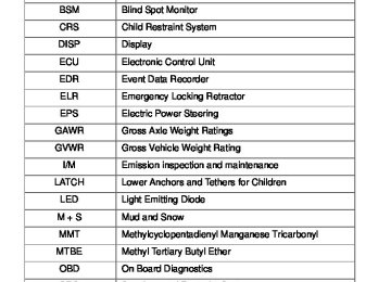
Abbreviation list Abbreviation/Acronym list
ABBREVIATIONS MEANING
Air Conditioning Anti-lock Brake System Accessory Automatic Locking Retractor Blind Spot Monitor Child Restraint System Display Electronic Control Unit Event Data Recorder Emergency Locking Retractor Electric Power Steering Gross Axle Weight Ratings Gross Vehicle Weight Rating Emission inspection and maintenance Lower Anchors and Tethers for Children Light Emitting Diode Mud and Snow Methylcyclopentadienyl Manganese Tricarbonyl Methyl Tertiary Butyl Ether On Board Diagnostics Supplemental Restraint System Tire Identification Number Tire Pressure Warning System Traction Control Vehicle Identification Number Vehicle Stability Control
A/C ABS ACC ALR BSM CRS DISP ECU EDR ELR EPS GAWR GVWR
I/M
LATCH LED M + S MMT MTBE OBD SRS TIN TPMS TRAC VIN VSC
520
For your information
Main Owner’s Manual
Please note that this manual covers all models and all equipment, including options. Therefore, you may find some explanations for equipment not installed on your vehicle. All specifications provided in this manual are current at the time of printing. However, because of the Toyota policy of continual product improvement, we reserve the right to make changes at any time without notice. Depending on specifications, the vehicle shown in the illustrations may differ from your vehicle in terms of equipment.
Noise from under vehicle after turning off the hybrid system
Approximately five hours after the hybrid system is turned off, you may hear sound coming from under the vehicle for several minutes. This is the sound of a fuel evaporation leakage check and, it does not indicate a malfunction.
Accessories, spare parts and modification of your Toyota
is not responsible
these products and
A wide variety of non-genuine spare parts and accessories for Toyota vehicles are currently available on the market. You should know that Toyota does not warrant their performance, repair, or replacement, or for any damage they may cause to, or adverse effect they may have on, your Toyota vehicle. This vehicle should not be modified with non-genuine Toyota products. Modification with non-genuine Toyota products could affect its performance, safety or durability, and may even violate governmental regulations. In addition, damage or performance problems resulting from the modification may not be covered under warranty.
for
20
Installation of a mobile two-way radio system
The installation of a mobile two-way radio system in your vehicle could affect electronic systems such as: ●Multiport fuel injection system/sequential multiport fuel injection system ●Cruise control system ●Anti-lock brake system ●SRS airbag system ●Seat belt pretensioner system Be sure to check with your Toyota dealer for precautionary measures or spe- cial instructions regarding installation of a mobile two-way radio system. High voltage parts and cables on the hybrid vehicles emit approximately the same amount of electromagnetic waves as the conventional gasoline pow- ered vehicles or home electronic appliances despite of their electromagnetic shielding. Unwanted noise may occur in the reception of the mobile two-way radio.
21
Vehicle data recordings
Your Toyota is equipped with several sophisticated computers that will record certain data, such as: • Engine speed • Electric motor speed (traction motor speed) • Accelerator status • Brake status • Vehicle speed • Shift position • Hybrid battery (traction battery) status The recorded data varies according to the vehicle grade level and options with which it is equipped. Furthermore, these computers do not record con- versations, sounds or pictures. ● Data usage Toyota may use the data recorded in these computers to diagnose malfunc- tions, conduct research and development, and improve quality. Toyota will not disclose the recorded data to a third party except: • With the consent of the vehicle owner or with the consent of the lessee if
•
the vehicle is leased In response to an official request by the police, a court of law or a govern- ment agency
• For use by Toyota in a law suit • For research purposes where the data is not tied to a specific vehicle or
vehicle owner
● Usage of data collected through Safety Connect (U.S.mainland only) If your Toyota has Safety Connect and if you have subscribed to those ser- vices, please refer to the Safety Connect Telematics Subscription Service Agreement for information on data collected and its usage.
22
Event data recorder
This vehicle is equipped with an event data recorder (EDR). The main pur- pose of an EDR is to record, in certain crash or near crash-like situations, such as an air bag deployment or hitting a road obstacle, data that will assist in understanding how a vehicle’s systems performed. The EDR is designed to record data related to vehicle dynamics and safety systems for a short period of time, typically 30 seconds or less. The EDR in this vehicle is designed to record such data as: • How various systems in your vehicle were operating; • Whether or not the driver and passenger safety belts were buckled/fas-
tened;
pedal; and,
• How far (if at all) the driver was depressing the accelerator and/or brake
• How fast the vehicle was traveling. These data can help provide a better understanding of the circumstances in which crashes and injuries occur. NOTE: EDR data are recorded by your vehicle only if a non-trivial crash situ- ation occurs; no data are recorded by the EDR under normal driving condi- tions and no personal data (e.g., name, gender, age, and crash location) are recorded. However, other parties, such as law enforcement, could combine the EDR data with the type of personally identifying data routinely acquired during a crash investigation. To read data recorded by an EDR, special equipment is required, and access to the vehicle or the EDR is needed. In addition to the vehicle manufacturer, other parties, such as law enforcement, that have the special equipment, can read the information if they have access to the vehicle or the EDR.
23
● Disclosure of the EDR data Toyota will not disclose the data recorded in an EDR to a third party except when: • An agreement from the vehicle’s owner (or the lessee for a leased vehicle)
•
is obtained In response to an official request by the police, a court of law or a govern- ment agency
• For use by Toyota in a law suit However, if necessary, Toyota may: • Use the data for research on vehicle safety performance • Disclose the data to a third party for research purposes without disclosing
information about the specific vehicle or vehicle owner
Scrapping of your Toyota
The SRS airbag and seat belt pretensioner devices in your Toyota contain explosive chemicals. If the vehicle is scrapped with the airbags and seat belt pretensioners left as they are, this may cause an accident such as fire. Be sure to have the systems of the SRS airbag and seat belt pretensioner removed and disposed of by a qualified service shop or by your Toyota dealer before you scrap your vehicle.
Perchlorate Material
Special handling may apply, See www.dtsc.ca.gov/hazardouswaste/perchlorate. Your vehicle has components that may contain perchlorate. These compo- nents may include airbag, seat belt pretensioners, and wireless remote con- trol batteries.
24
CAUTION
■General precautions while driving
Driving under the influence: Never drive your vehicle when under the influ- ence of alcohol or drugs that have impaired your ability to operate your vehi- cle. Alcohol and certain drugs delay reaction time, impair judgment and reduce coordination, which could lead to an accident that could result in death or serious injury. Defensive driving: Always drive defensively. Anticipate mistakes that other drivers or pedestrians might make and be ready to avoid accidents. Driver distraction: Always give your full attention to driving. Anything that dis- tracts the driver, such as adjusting controls, talking on a cellular phone or reading can result in a collision with resulting death or serious injury to you, your occupants or others.
■General precaution regarding children’s safety
Never leave children unattended in the vehicle, and never allow children to have or use the key. Children may be able to start the vehicle or shift the vehicle into neutral. There is also a danger that children may injure themselves by playing with the windows, the moon roof, or other features of the vehicle. In addition, heat build-up or extremely cold temperatures inside the vehicle can be fatal to children.
■Disposal of the hybrid battery (traction battery)
If your vehicle is disposed of without the hybrid battery having been removed, there is a danger of serious electric shock if high voltage parts, cables and their connectors are touched. In the event that your vehicle must be disposed of, the hybrid battery must be disposed of by your Toyota dealer or a qualified service shop. If the hybrid battery is not disposed of properly, it may cause electric shock that can result in death or serious injury.
25
Symbols used throughout this manual
Cautions & Notices
CAUTION
This is a warning against something which, if ignored, may cause death or serious injury to people. You are informed about what you must or must not do in order to reduce the risk of death or serious injury to yourself and others.
NOTICE
This is a warning against something which, if ignored, may cause damage to the vehicle or its equipment. You are informed about what you must or must not do in order to avoid or reduce the risk of damage to your Toyota and its equipment.
Symbols used in illustrations
Safety symbol The symbol of a circle with a slash through it means “Do not”, “Do not do this”, or “Do not let this happen”.
Arrows indicating operations
Indicates the action (pushing, turning, etc.) used to operate switches and other devices. Indicates the outcome of an operation (e.g. a lid opens).
26
TABLE OF CONTENTS
1 Before driving
Information on the hybrid system and adjusting and operating features such as door locks, mirrors, and steering column.
2 When driving
Driving, stopping and safe-driving information.
3 Interior fea-
tures
Air conditioning and audio systems, as well as other in- terior features for a comfortable driving experience.
4 Maintenance
and care
Cleaning and protecting your vehicle, performing do-it- yourself maintenance, and maintenance information.
5 When trouble
arises
What to do if the vehicle needs to be towed, gets a flat tire, or is involved in an accident.
6 Vehicle
specifications
Detailed vehicle information.
7 For owners
Reporting safety defects for U.S. owners, and seat belt and SRS airbag instructions for Canadian owners
Index
Alphabetical listing of information contained in this manual.
1-1. Hybrid system Hybrid system
Your vehicle is a hybrid vehicle. It has characteristics different from conventional vehicles. Be sure you are closely familiar with the char- acteristics of your vehicle, and operate with care. The hybrid system combines the use of a gasoline engine and an electric motor (traction motor) according to driving conditions, improving fuel efficiency and reducing exhaust emissions.
Gasoline engine Electric motor (traction motor)