- 2006 Subaru Legacy Owners Manuals
- Subaru Legacy Owners Manuals
- 2004 Subaru Legacy Owners Manuals
- Subaru Legacy Owners Manuals
- 2008 Subaru Legacy Owners Manuals
- Subaru Legacy Owners Manuals
- 2005 Subaru Legacy Owners Manuals
- Subaru Legacy Owners Manuals
- 2007 Subaru Legacy Owners Manuals
- Subaru Legacy Owners Manuals
- 2000 Subaru Legacy Owners Manuals
- Subaru Legacy Owners Manuals
- 2003 Subaru Legacy Owners Manuals
- Subaru Legacy Owners Manuals
- 2012 Subaru Legacy Owners Manuals
- Subaru Legacy Owners Manuals
- 2001 Subaru Legacy Owners Manuals
- Subaru Legacy Owners Manuals
- 2010 Subaru Legacy Owners Manuals
- Subaru Legacy Owners Manuals
- 2011 Subaru Legacy Owners Manuals
- Subaru Legacy Owners Manuals
- 2009 Subaru Legacy Owners Manuals
- Subaru Legacy Owners Manuals
- 2002 Subaru Legacy Owners Manuals
- Subaru Legacy Owners Manuals
- Download PDF Manual
-
Aluminum wheels
Windshield washer fluid
Use only those wheels that are specified for your vehicle. Wheels not meeting specifications could interfere with brake caliper opera- tion and may cause the tires to rub against the wheel well housing dur- ing turns. The resulting loss of vehicle control could lead to an accident.
Aluminum wheels can be scratched and damaged easily. Handle them carefully to maintain their appearance, performance, and safety. . When any of the wheels is removed and replaced for tire rotation or to change a flat, always check the tightness of the wheel nuts after driving approximately 600
miles (1,000 km). is loose, If any nut tighten it to the specified torque. . Never apply oil to the threaded parts, wheel nuts, or the wheel. . Never let the wheel rub against sharp protrusions or curbs. . Be sure to fit tire chains on uniformly and completely around the tire, otherwise the chains may scratch the wheel. . When wheel nuts, balance weights, or the center cap is replaced, be sure to replace them with genuine SUBARU parts designed for aluminum wheels.tapered surface of
CAUTION
Never use engine coolant as washer fluid because it could cause paint damage.
If you spray washer fluid on the windshield but the supply of washer fluid appears to diminish, check the level of washer fluid in the tank.
11
– CONTINUED –
北米Model "A2440BE-B" EDITED: 2007/ 5/ 7
Black plate (396,1)
level gauge or the “Full” mark on the tank. Use windshield washer fluid. If windshield washer fluid is unavailable use clean water. In areas where water freezes in winter, use an anti-freeze type windshield washer fluid. SUBARU Windshield Washer Fluid contains 58.5% methyl alcohol and 41.5% surfactant, by volume. Its freezing tem- perature varies according to how much it is diluted, as indicated in the following table.
temperature, it may freeze and block the nozzles.
CAUTION
Adjust the washer fluid concentra- tion appropriately for the outside temperature. If the concentration is inappropriate, sprayed washer fluid may freeze on the windshield and obstruct your view, and the fluid may freeze in the reservoir tank.
Washer Fluid Concentration
30%
50%
100%
Freezing
Temperature 10.48F (−128C) −48F (−208C) −498F (−458C)
In order to prevent freezing of washer fluid, check the freezing temperatures in the table above when adjusting the fluid concentration to the outside temperature. If you fill the reservoir tank with a fluid with a different concentration from the one used previously, purge the old fluid from the piping between the reservoir tank and washer nozzles by operating the washer for a certain period of time. Otherwise, if the concentration of the fluid remaining in the piping is too low for the outside
11-42 Maintenance and service
Washer fluid level gauge
Remove the washer tank filler cap, then check the fluid level indicated by the level gauge (attached to the inside of the cap). is near the “Low” mark, add If the level fluid until it reaches the “Hi” level on the
北米Model "A2440BE-B" EDITED: 2007/ 5/ 7
. Return the passenger-side wiper arm to its original position before returning the driver-side wiper arm to its original position. Otherwise, the passenger-side wiper assembly and driver-side wiper assembly will touch each other, possibly resulting in scratches.
If you cannot eliminate the streaking even after following this method, replace the wiper blades using the following proce- dures:
& Windshield wiper blade as-
sembly
1. Raise the windshield wiper arm on the driver’s side. 2. Next, raise the windshield wiper arm on the passenger’s side.
Replacement of wiper blades
Grease, wax, insects, or other materials on the windshield or the wiper blade results in jerky wiper operation and streak- ing on the glass. If you cannot remove the streaks after operating the windshield washer or if the wiper operation is jerky, clean the outer surface of the windshield (or rear window) and the wiper blades using a sponge or soft cloth with a neutral detergent or mild-abrasive cleaner. After cleaning, rinse the windshield and wiper blades with clean water. The windshield is clean if beads do not form when you rinse the windshield with water.
CAUTION
. Do not clean the wiper blades with gasoline or a solvent, such as paint thinner or benzine. This will cause deterioration of the wiper blades.
. When you wish to raise the passenger-side wiper arm, first raise the driver-side wiper arm. Otherwise, the passenger-side wiper assembly and driver-side wiper assembly will touch each other, possibly resulting in scratches.
Black plate (397,1)
Maintenance and service 11-43
1) Stopper
3. Remove the wiper blade assembly by holding its pivot area and pushing it in the direction shown by the arrow while de- pressing the wiper blade stopper. 4. Install the wiper blade assembly to the wiper arm. Make sure that it locks in place. 5. Lower the windshield wiper arm on the passenger’s side slowly while supporting it by hand. 6. Next, lower the windshield wiper arm on the driver’s side slowly while support- ing it by hand.
11
– CONTINUED –
北米Model "A2440BE-B" EDITED: 2007/ 5/ 7
11-44 Maintenance and service
& Windshield wiper blade rub-
ber
Black plate (398,1)
with the grooves in the rubber and slide the blade rubber assembly into the metal support until it locks.
1) Metal support
1. Grasp the locked end of the blade rubber assembly and pull it firmly until the stoppers on the rubber are free of the metal support.
1) Metal spines
2. If the new blade rubber is not provided with two metal spines, remove the metal spines from the old blade rubber and install them in the new blade rubber.
1) Stopper
4. Be sure to position the claws at the end of the metal support between the stoppers on the rubber as shown. If the rubber is not retained properly, the wiper blade may scratch the windshield.
3. Align the claws of the metal support
北米Model "A2440BE-B" EDITED: 2007/ 5/ 7
& Rear window wiper blade
assembly
1. Raise the wiper arm off window.
the rear
Black plate (399,1)
Maintenance and service 11-45
& Rear window wiper blade
rubber
2. Turn the wiper blade assembly coun- terclockwise.
3. Pull the wiper blade assembly toward you to remove it from the wiper arm.
1. Pull out the end of the blade rubber assembly to unlock it from the plastic support.
11
– CONTINUED –
北米Model "A2440BE-B" EDITED: 2007/ 5/ 7
Black plate (400,1)
ends. If the rubber is not retained properly, the wiper may scratch the rear window glass. 5. Install the wiper blade assembly to the wiper arm. Make sure that it locks in place. 6. Hold the wiper arm by hand and slowly lower it in position.
11-46 Maintenance and service
2. Pull the blade rubber assembly out of the plastic support.
1) Metal spines
3. If the new blade rubber is not provided with two metal spines, remove the metal spines from the old blade rubber and install them in the new blade rubber.
4. Align the claws of the plastic support with the grooves in the blade rubber assembly, then slide the blade rubber assembly into place.
Securely retain both ends of the rubber with the stoppers on the plastic support
北米Model "A2440BE-B" EDITED: 2007/ 5/ 7
Battery
WARNING
. Before beginning work on or near any battery, be sure to extinguish all cigarettes, matches, and light- ers. Never expose a battery to an open flame or electric sparks. Batteries give off a gas which is highly flammable and explosive. . For safety, in case an explosion does occur, wear eye protection or shield your eyes when work- ing near any battery. Never lean over a battery.
. Do not let battery fluid contact eyes, skin, fabrics, or paint be- cause battery fluid is a corrosive acid. If battery fluid gets on your skin or in your eyes, immediately flush the area with water thor- oughly. Seek medical help imme- diately if acid has entered the eyes. If battery fluid is accidentally swallowed, immediately drink a large amount of milk or water, and seek medical attention im- mediately.
. To lessen the risk of sparks,
remove rings, metal watchbands, and other metal jewelry. Never allow metal tools to contact the positive battery terminal and any- thing connected to it WHILE you are at the same time in contact with any other metallic portion of the vehicle because a short cir- cuit will result.
. Keep everyone including children
away from the battery.
. Charge the battery in a well-
ventilated area.
. Battery posts, terminals, and re- lated accessories contain lead and lead compounds, chemicals known to the State of California to cause cancer and reproductive harm. Batteries also contain other chemicals known to the State of California to cause can- cer. Wash hands after handling.
CAUTION
Never use more than 10 amperes when charging the battery because it will shorten battery life.
It is unnecessary to periodically check the battery fluid level or periodically refill with
Black plate (401,1)
Maintenance and service 11-47
distilled water.
11
北米Model "A2440BE-B" EDITED: 2007/ 5/ 7
Black plate (402,1)
11-48 Maintenance and service
Fuses
CAUTION
Never replace a fuse with one hav- ing a higher rating or with material other than a fuse because serious damage or a fire could result.
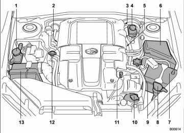
The fuses are designed to melt during an overload to prevent damage to the wiring harness and electrical equipment. The fuses are located in two fuse boxes. One is located under the instrument panel behind the fuse box cover on the driver’s seat side.
Open the lid that is located above the hood release knob and pull it toward you to remove it.
The spare fuses are stored in the main fuse box cover in the engine compart- ment.
The other one is housed in the engine compartment.
The fuse puller is stored in the main fuse box in the engine compartment.
北米Model "A2440BE-B" EDITED: 2007/ 5/ 7
Black plate (403,1)
Maintenance and service 11-49
Main fuse
Main fuse box
The main fuses are designed to melt during an overload to prevent damage to the wiring harness and electrical equip- ment. Check the main fuses if any electrical component fails to operate (ex- cept the starter motor) and other fuses are good. A melted main fuse must be replaced. Use only replacements with the same specified rating as the melted main fuse. is replaced, have the electrical system checked by your nearest SUBARU dealer.
If a main fuse blows after
it
北米Model "A2440BE-B" EDITED: 2007/ 5/ 7
11
If
Inspect
the fuse.
4. Pull out the fuse with the fuse puller. 5. it has blown, replace it with a spare fuse of the same rating. 6. this indicates that its system has a problem. Contact your SUBARU dealer for repairs.
the same fuse blows again,
If
1) Good 2) Blown
inspect
If any lights, accessories or other electrical controls do not operate, the corresponding fuse. If a fuse has blown, replace it. 1. Turn the ignition switch to the “LOCK” position and turn off all electrical acces- sories. 2. Remove the cover. 3. Determine which fuse may be blown. The back side of each fuse box cover and the “Fuses and circuits” section in chapter 12 in this manual show the circuit for each fuse.
Black plate (404,1)
11-50 Maintenance and service
Installation of accessories
Always consult your SUBARU dealer before installing fog lights or any other electrical equipment in your vehicle. Such accessories may cause the electronic system to malfunction if they are incor- rectly installed or if they are not suited for the vehicle.
北米Model "A2440BE-B" EDITED: 2007/ 5/ 7
Replacing bulbs
Black plate (405,1)
Maintenance and service 11-51
11
– CONTINUED –
北米Model "A2440BE-B" EDITED: 2007/ 5/ 7
11-52 Maintenance and service
1) 2) 3) 4) 5) 6) 7) 8)
High beam headlight Low beam headlight Front turn signal/Parking and front side marker light Map light Dome light Door step light Vanity mirror light Front fog light
Except OUTBACK
OUTBACK
Trunk room light (Sedan)
9) 10) High mount stop light (Sedan) 11) Rear turn signal light (Sedan) 12) Back-up light (Sedan) 13) Brake/tail and rear side marker light (Sedan) 14) Cargo area light (Station wagon) 15) Brake/tail light (Station wagon) 16) Rear side marker light (Station wagon) 17) Rear turn signal light (Station wagon) 18) Back-up light (Station wagon) 19)
Licence plate light
Black plate (406,1)
Wattage
Bulb No.
CAUTION
12V-60W 12V-55W 12V-27/8W 12V-8W 12V-8W 12V-3W 12V-3W
12V-55W
12V-51W
12V-5W 12V-21W 12V-21W 12V-16W 12V-21/5W 12V-13W 12V-21/5W 12V-5W 12V-21W 12V-16W 12V-5W
9005 (HB3) H7
3457A ––
–
–
H3
9006 (HB4)
(W5W) (W21W) (WY21W) 921
(W21/5W) –(W21/5W) 168
(WY21W) 921
168 (W5W)Replace any bulb only with a new bulb of the specified wattage. Using a bulb of different wattage could result in a fire.
& Headlight
CAUTION
Halogen headlight bulbs become very hot while in use. If you touch the bulb surface with bare hands or greasy gloves, finger prints or grease on the bulb surface develop into hot spots, causing the bulb to break. If there are finger prints or grease on the bulb surface, wipe them away with a soft cloth mois- tened with alcohol.
NOTE . If headlight aiming is required, con- sult your SUBARU dealer for proper adjustment of the headlight aim. . It may be difficult to replace the bulbs. Have the bulbs replaced by your SUBARU dealer if necessary.
北米Model "A2440BE-B" EDITED: 2007/ 5/ 7
! Low beam light bulbs
2. Use a screwdriver to remove the secured clip of the washer tank. To make it easy to access the bulb, move the washer tank to the horizontal direction. (left-hand side)
Right-hand side
1. Use a screwdriver to undo the clips on the air intake duct, then remove the air intake duct. (right-hand side)
3. Remove the bulb cover, by turning it counterclockwise.
Black plate (407,1)
Maintenance and service 11-53
4. Disconnect the electrical connector. 5. Remove the retainer spring. 6. Replace the bulb, then set the retainer spring securely. 7. Reconnect the electrical connector. 8. 9. (right-hand side) 10. Set the washer tank to the original place and secure it by clip. (left-hand side)
Install the bulb cover. Install
the air intake duct with clips.
11
Left-hand side
– CONTINUED –
北米Model "A2440BE-B" EDITED: 2007/ 5/ 7
11-54 Maintenance and service
! High beam light bulbs
2. Use a screwdriver to remove the secured clip of the washer tank. To make it easy to access the bulb, move the washer tank to the horizontal direction. (left-hand side)
Right-hand side
1. Use a screwdriver to undo the clips on the air intake duct, then remove the air intake duct. (right-hand side)
Left-hand side
the electrical connector
3. Disconnect from the bulb. 4. Remove the bulb from the headlight assembly by turning it counterclockwise. 5. Replace the bulb with new one. At this time, use care not to touch the bulb surface. 6. Reconnect the electrical connector. 7. To install assembly, turn it clockwise until it clicks. 8. (right-hand side) 9. Set
the washer tank to the original
the air intake duct with clips.
the bulb to the headlight
Install
Black plate (408,1)
place and secure it by clip. (left-hand side)
& Front turn signal light and
parking light
It may be difficult to replace the bulbs. Have the bulbs replaced by your SUBARU dealer if necessary.
& Front fog light (if equipped) It may be difficult to replace the bulbs. Have the bulbs replaced by your SUBARU dealer if necessary.
北米Model "A2440BE-B" EDITED: 2007/ 5/ 7
& Rear combination lights ! Sedan
Black plate (409,1)
Maintenance and service 11-55
! Station wagon
1. Push the knobs of the cover to open the cover.
1) Rear turn signal light 2) Back-up light 3) Brake/tail and rear side marker light
2. Remove the bulb holder from the rear combination light assembly by turning it counterclockwise. 3. Pull the bulb out of the bulb holder and replace it with a new one. 4. Set into the rear the bulb holder combination light assembly and turn it clockwise until it locks. 5. Securely lock the cover against trunk trim.
the
1. Using a Phillips screwdriver, remove the upper and lower screws.
11
– CONTINUED –
北米Model "A2440BE-B" EDITED: 2007/ 5/ 7
11-56 Maintenance and service
2. Wrap tape around a flat-head screw- driver, then insert the screwdriver into the gap between the side cover and rear combination lamp and use it as a lever to undo clip 1 in the illustration shown. Undo clips 2 and 3 in the same way, then remove the side cover.
3. Remove the upper and lower screws. Then, straightly slide the rear combination lamp assembly rearward and remove it from the vehicle.
Black plate (410,1)
3) Rear side marker light
4. Remove the bulb holder from the rear combination light assembly by turning it counterclockwise. 5. Pull the bulb out of the bulb holder and replace it with a new one. 6. Set into the rear the bulb holder combination light assembly and turn it clockwise until it locks.
7.
Insert the harness into the holder.
1) Brake/tail light 2) Rear turn signal light
北米Model "A2440BE-B" EDITED: 2007/ 5/ 7
Black plate (411,1)
& Back-up light (Station wagon)
and remove it.
Maintenance and service 11-57
8. Reinstall the rear combination light assembly by sliding the two-pronged part of the combination light assembly securely to each holder of the vehicle side.
1. Apply a flat-head screwdriver to the corner of the light cover as shown in the illustration, and pry the light cover off from the rear gate trim.
9. Tighten the upper and lower screws. 10. Reinstall the side cover.
2. Turn the bulb socket counterclockwise
3. Pull the bulb out of the bulb socket and replace it with a new one. 4. Install clockwise. rear gate.
the bulb socket by turning it Install the light cover on the
& License plate light ! Sedan It may be difficult to replace the bulbs. Have the bulbs replaced by your SUBARU dealer if necessary.
11
– CONTINUED –
北米Model "A2440BE-B" EDITED: 2007/ 5/ 7
Black plate (412,1)
11-58 Maintenance and service
! Station wagon
new bulb. 4. Reinstall the lens. 5. Tighten the mounting screws.
& Dome light
1. Remove the mounting screws using a Phillips screwdriver. 2. Remove the lens.
2. Turn the bulb until the flat surfaces at its ends are aligned vertically. Pull the bulb straight downward to remove it. Install a new bulb. 3. Reinstall the lens.
1. Remove the lens by prying the edge of the lens with a flat-head screwdriver.
3. Pull the bulb out of the socket. Install a
北米Model "A2440BE-B" EDITED: 2007/ 5/ 7
Black plate (413,1)
Maintenance and service 11-59
& Map light
straight downward to remove it. 3. Install a new bulb. 4. Reinstall the lens.
& Vanity mirror light
1. Remove the lens by prying the edge of the lens with a flat-head screwdriver.
2. Pull the bulb out of the socket. Install a new bulb. 3. Reinstall the lens.
& Door step light
1. Remove the lens by prying the edge of the lens with a flat-head screwdriver.
11
2. Turn the bulb until the flat surfaces at its ends are aligned vertically. Pull the bulb
– CONTINUED –
北米Model "A2440BE-B" EDITED: 2007/ 5/ 7
11-60 Maintenance and service
1. Remove the lens by prying the edge of the lens with a flat-head screwdriver.
& Cargo area light (Station wa-
gon)
2. Pull the bulb out of the socket. Install a new bulb. 3. Reinstall the lens.
1. Remove the lens by prying the edge of the lens with a flat-head screwdriver.
2. Pull the bulb out of the socket. Install a
Black plate (414,1)
new bulb. 3. Reinstall the lens.
& Trunk light (Sedan)
1. Push both sides of the light cover, and then remove the cover by pulling it out. 2. Pull the bulb out of the socket. Install a new bulb. 3. Reinstall the cover.
& High mount stop light (Se-
dan)
It may be difficult to replace the bulbs. Have the bulbs replaced by your SUBARU dealer if necessary.
北米Model "A2440BE-B" EDITED: 2007/ 5/ 7
Black plate (23,1)
Specifications
Specifications ..................................................... 12-2
Dimensions........................................................ 12-2
Engine ............................................................... 12-3
Electrical system................................................ 12-3
Capacities .......................................................... 12-4
Tires .................................................................. 12-5
Wheel alignment ................................................ 12-5Fuses and circuits .............................................
12-6
Fuse panel located in the passenger
compartment ...................................................
Fuse panel located in the engine
compartment ................................................... Bulb chart........................................................... Vehicle identification .......................................
12-6
12-8
12-9
12-1112
北米Model "A2440BE-B" EDITED: 2007/ 5/ 7
Black plate (418,1)
12-2 Specifications
Specifications
These specifications are subject to change without notice. & Dimensions
Item
Sedan
Legacy
Station wagon
Non- turbo
Turbo
Sedan
OUTBACK
Station wagon
in (mm)
2.5-liter
2.5-liter
3.0-liter
2.5-liter
3.0-liter
Except 2.5GT spec.B
2.5GT spec.B
185.0 (4,700)
68.1 (1,730)
56.1
(1,425)
56.5
(1,435)
105.1 (2,670)
58.9 (1,495)
58.5 (1,485)
Overall length
Overall width
Overall height
Wheel base
Tread
Front
Rear
Ground clearance
188.4 (4,785)
68.1 (1,730)
185.0 (4,700)
69.7 (1,770)
58.1 (1,475)
56.5 (1,435)
105.1 (2,670)
58.9 (1,495)
58.5 (1,485)
105.1 (2,670)
58.9 (1,495)
58.5 (1,485)
6.3 (160)
5.9
(150)6.3
(160)5.9
(150)6.1
(155)Non- turbo
Turbo
189.0 (4,800)
69.7 (1,770)
63.2 (1,605)
105.1 (2,670)
58.9 (1,495)
58.7 (1,490)
8.5
(215)8.7
(220)8.5 (215)
北米Model "A2440BE-B" EDITED: 2007/ 5/ 7
Black plate (419,1)
Specifications 12-3
& Engine
Engine model
Engine type
Displacement cu-in (cc) Bore 6 Stroke in (mm) Compression ratio
Firing order
& Electrical system
EJ253
(2.5-liter, SOHC, non-turbo)
EJ255
(2.5-liter, DOHC, turbo)
EZ30D
(3.0-liter, DOHC, non-turbo)
Horizontally opposed, liquid cooled 4 cylinder,
4 stroke gasoline engine
Horizontally opposed, liquid cooled 6 cylinder,
4 stroke gasoline engine
150 (2,457)
3.92 6 3.11 (99.5 6 79.0)
10.0 : 1
8.4 : 1
1 – 3 – 2 – 4
183 (3,000)
3.51 6 3.15 (89.2 6 80.0)
10.7 : 1
1 – 6 – 3 – 2 – 5 – 4
Battery type and capacity (5HR)
2.5-liter models
MT
AT
Alternator
Spark plugs
3.0-liter models
2.5-liter non-turbo models
2.5-liter turbo models
3.0-liter models
55D23L (12V-48AH)
75D23L (12V-52AH)
75D23L (12V-52AH)
12V-110A
FR5AP-11 (NGK) SILFR6A (NGK)
ILFR6B (NGK)
12
– CONTINUED –
北米Model "A2440BE-B" EDITED: 2007/ 5/ 7
12-4 Specifications
& Capacities
Fuel tank Engine oil
Transmission oil (MT)
2.5-liter models
3.0-liter models
5-speeds
6-speeds
Transmission fluid (AT)
2.5-liter non-turbo models
2.5-liter turbo and 3.0-liter models
AT differential gear oil
2.5-liter non-turbo models
Rear differential gear oil
Turbo 6-speeds MT models
2.5-liter turbo and 3.0-liter models
Power steering fluid Engine coolant
Other models
2.5-liter non-turbo models MT AT
2.5-liter turbo models
3.0-liter models
MT
AT
Black plate (420,1)
16.9 US gal (64 liters, 14.1 Imp gal)
4.2 US qt (4.0 liters, 3.5 Imp qt)
5.8 US qt (5.5 liters, 4.8 Imp qt)
3.7 US qt (3.5 liters, 3.1 Imp qt)
4.3 US qt (4.1 liters, 3.6 Imp qt)
9.8 US qt (9.3 liters, 8.2 Imp qt)
10.4 US qt (9.8 liters, 8.6 Imp qt)
1.3 US qt (1.2 liters, 1.1 Imp qt)
1.5 US qt (1.4 liters, 1.2 Imp qt)
1.1 US qt (1.0 liter, 0.9 Imp qt)
0.8 US qt (0.8 liter, 0.7 Imp qt)
0.7 US qt (0.7 liter, 0.6 Imp qt)
6.8 US qt (6.4 liters, 5.6 Imp qt)
6.7 US qt (6.3 liters, 5.5 Imp qt)
7.7 US qt (7.3 liters, 6.4 Imp qt)
7.6 US qt (7.2 liters, 6.3 Imp qt) 7.6 US qt (7.2 liters, 6.3 Imp qt)
北米Model "A2440BE-B" EDITED: 2007/ 5/ 7
Black plate (421,1)
Specifications 12-5
& Tires
Tire size
Wheel size Pressure
Temporary spare tire
Front
Rear
Rear at trailer tow- ing
Size
Pressure
& Wheel alignment
Toe
Camber
Item
Front
Rear
Front
Rear
P205/55R16
89H
P225/60R16
97H
P205/50R17
88V
16 6 6.5JJ
32 psi
(220 kPa, 2.2 kgf/cm2)
30 psi
(210 kPa, 2.1 kgf/cm2)
–
32 psi
(220 kPa, 2.2 kgf/cm2)
30 psi
(210 kPa, 2.1 kgf/cm2)
32 psi
(220 kPa, 2.2 kgf/cm2)
33 psi
(230 kPa, 2.3 kgf/cm2)
32 psi
(220 kPa, 2.2 kgf/cm2)
–
215/45R17
91W
17 6 7 JJ
35 psi
(240 kPa, 2.4 kgf/cm2)
33 psi
(230 kPa, 2.3 kgf/cm2)
P225/55R17
95V
215/45R18
89Y
P215/45R18
89W
18 6 7 JJ
33 psi
(230 kPa, 2.3 kgf/cm2)
32 psi
(220 kPa, 2.2 kgf/cm2)
–
32 psi
(220 kPa, 2.2 kgf/cm2)
30 psi
(210 kPa, 2.1 kgf/cm2)
32 psi
(220 kPa, 2.2 kgf/cm2)
T135/80R16
T155/70D17
T135/80R16
T135/70D17
T155/70D17
T155/70D17
60 psi (420 kPa, 4.2 kgf/cm2)
Legacy
Sedan
Station wagon
−0815’
−0840’
−0830’
0 in (0 mm)
0 in (0 mm)
OUTBACK
Station wagon
0840’ −0810’
12
北米Model "A2440BE-B" EDITED: 2007/ 5/ 7
Black plate (422,1)
12-6 Specifications
Fuses and circuits & Fuse panel located in the passenger compartment
Fuse panel
10
11
12
Fuse rating 20A
Empty
15A 15A
15A
7.5A
15A
20A
20A
7.5A
7.5A
15A
Circuit
. Cargo fan
Trailer hitch connector
rear
view mirrors
Integrated unit
Front wiper deicer relay
. Door locking . Moonroof . Combination meter . Remote control . Seat heater relay . Vanity mirror light . Combination meter . Stop light . Mirror heater . Power supply (Battery) . Clock . Automatic transmission . Engine control unit
Front wiper deicer
Turn signal unit
Integrated unit
unit
北米Model "A2440BE-B" EDITED: 2007/ 5/ 7
Fuse panel
13
14
15
16
17
18
19
20
21
22
23
24
25
26
27
Fuse rating 20A
15A
Empty
10A
15A
10A
7.5A
10A
7.5A
15A
15A
15A
15A
7.5A
15A
Black plate (423,1)
Specifications 12-7
Circuit
Fog light
Front wiper Front wiper washer
. Blower fan . Auto air conditioner unit . Headlight left side relay . ABS/Vehicle dynamics
Integrated unit
control unit
Circuit
. Cargo socket . Position light . Rear combination light
Tail light
Illumination
. Seat heaters . Back-up light . Headlight right side re-
lay
Fuse panel
28
29
30
31
32
33
Fuse rating 15A
15A
30A
7.5A
7.5A
7.5A
. Cigarette lighter socket . Starter relay . Air conditioner . Rear window defogger
relay coil
. Rear wiper . Rear window washer . Audio unit . Clock . SRS airbag system . Power window relay . Blower fan
12
– CONTINUED –
北米Model "A2440BE-B" EDITED: 2007/ 5/ 7
12-8 Specifications
& Fuse panel located in the engine compartment
A) FWD socket (AT models – except Turbo models and 3.0-liter models) B) Main fuse
Fuse panel
10
11
12
13
14
15
16
17
Black plate (424,1)
Fuse rating 30A . ABS unit
Circuit
. Vehicle dynamics control
unit
25A . Main fan (3.0-liter models) 10A . Secondary air combina- tion valve (Turbo models) 25A . Sub fan (Except 3.0-liter
models) 25A . Main fan 20A . Audio 15A . Headlight (right side) 15A . Headlight (left side) 20A . Back-up light 15A . Horn 25A . Rear window defogger 15A . Fuel pump 15A . Automatic control unit
transmission
7.5A . Engine control unit 15A .
Turn and hazard warning flasher
20A . Parking switch 7.5A . Alternator
北米Model "A2440BE-B" EDITED: 2007/ 5/ 7
Bulb chart
Description Headlight
Low beam High beam Front fog light
Except OUTBACK OUTBACK
Front turn signal/Parking and front side marker light Rear combination light
Rear turn signal light (Se- dan) Brake/tail and rear side marker (Sedan) Brake/tail (Station wagon) Rear side marker (Station wagon) Rear turn signal light (Station wagon) Back-up light
High mount stop light (Sedan) License plate light
Wattage
12V-55W 12V-60W
12V-55W 12V-51W 12V-27/8W
12V-21W
12V-21/5W
12V-21/5W
12V-5W
12V-21W
12V-16W 12V-21W 12V-5W
Bulb No.
H7
9005 (HB3)H3
9006 (HB4) 3457A(WY21W)
(W21/5W)
(W21/5W)
168
(WY21W)
921
(W21W) 168 (W5W)Black plate (425,1)
Specifications 12-9
12
– CONTINUED –
北米Model "A2440BE-B" EDITED: 2007/ 5/ 7
Black plate (426,1)
12-10 Specifications
Description Trunk room light Cargo area light Dome light Map light Vanity mirror light Door step light
Wattage 12V-5W 12V-13W 12V-8W 12V-8W 12V-3W 12V-3W
Bulb No. W5W –
–
–
–
–
北米Model "A2440BE-B" EDITED: 2007/ 5/ 7
Vehicle identification
Black plate (427,1)
Specifications 12-11
1) Emission control label 2) Vehicle identification number 3) Certification and bar code label 4) 5) Vehicle identification number plate 6) Model number label 7)
Tire inflation pressure label
Fuel label
12
北米Model "A2440BE-B" EDITED: 2007/ 5/ 7
Black plate (25,1)
Consumer information and Reporting safety defects
For U.S.A. ........................................................... 13-2
Tire information.................................................. 13-2
Tire labeling ....................................................... 13-2
Recommended tire inflation pressure.................. 13-5
Glossary of tire terminology ............................... 13-6
Tire care – maintenance and safety practices...... 13-7
Vehicle load limit – how to determine.................. 13-8
Determining compatibility of tire and vehicle load capacities ......................................................13-11
Adverse safety consequences of overloading on handling and stopping and on tires ................ Steps for Determining Correct Load Limit......... Uniform tire quality grading standards .......... Treadwear ....................................................... Traction AA, A, B, C......................................... Temperature A, B, C......................................... Reporting safety defects (U.S.A.) ...................
13-11
13-11
13-12
13-12
13-12
13-13
13-1313
北米Model "A2440BE-B" EDITED: 2007/ 5/ 7
13-2 Consumer information and Reporting safety defects
For U.S.A.
The following information has been compiled according to Code of Federal Regulations “Title 49, Part 575”.
Tire information & Tire labeling Many markings (e.g. Tire size, Tire Identification Number or TIN) are placed on the sidewall of a tire by tire manufacturers. These marking can provide you with useful infor- mation on the tire. ! Tire size Your vehicle comes equipped with P-Metric tire size. It is important to understand the sizing system in selecting the proper tire for your vehicles. Here is a brief review of the tire sizing system with a break- down of its individual elements. ! P Metric With the P-Metric system, Section Width is measured in millimeters. To convert millimeters into inches, divide by 25.4. The Aspect Ratio (Section Height divided by Section Width) helps provide more dimen- sional the tire size.
information about
Black plate (430,1)
Example:
(1) P = Certain tire type used on light duty vehicles such as passen- ger cars (2) Section Width in millimeters (3) Aspect Ratio (= section height 7 section width). (4) R = Radial Construction (5) Rim diameter in inches (6) ZR = Speed category above 149 mph (240 km/h) ! Load and Speed Rating Descrip-
tions
The load and speed rating descrip- tions will appear following the size designation. facts They provide two important the number about designation is its load index. Sec- ond, the letter designation indicates
the tire. First,
北米Model "A2440BE-B" EDITED: 2007/ 5/ 7
Black plate (431,1)
the tire’s speed rating. Example:
(6) Load Index: A numerical code which specifies the maximum load a tire can carry at the speed indicated by its speed symbol, at maximum inflation pressure. For example, “88” means 1,234 lbs (560 kg), “87” means 1,201 lbs (545
kg), “86” means 1,168 lbs (530 kg)WARNING
Load indices apply only to the tire, not to the vehicle. Putting a load rated tire on any vehicle does not mean the vehicle can be loaded up to the tire’s rated load.
(7) Speed Rating: An alphabetical system describing a tire’s capability to travel at established and prede- termined speeds. For example, “V” means 149 mph
Consumer information and Reporting safety defects 13-3
(240 km/h)
individual elements.
WARNING
. Speed ratings apply only to the tire, not to the vehicle. Putting a speed rated tire on any vehicle does not mean the vehicle can be operated at the tire’s rated speed.
. The speed rating is void if the tires are worn out, da- maged, repaired, retreaded, or otherwise altered from If their original condition. tires are repaired, re- treaded, or otherwise al- tered, they may not be sui- table for original equipment tire designed loads and speeds.
! Tire Identification Number (TIN) Tire Identification Number (TIN) is marked on the intended outboard sidewall. The TIN is composed of four groups. Here is a brief review of the TIN with a breakdown of its
(1) Manufacturer’s Identification Mark (2) Tire Size (3) Tire Type Code (4) Date of Manufacture The first two figures identify the week, starting with “01” to represent the first full week of the calendar year; the second two figures repre- sent the year. For example, 0101
means the 1st week of 2001. ! Other markings The following makings are also placed on the sidewall. ! Maximum permissible inflationpressure
The maximum cold inflation pres- sure to which this tire may be “300 kpa inflated. For example, (44 PSI) MAX. PRESS”
– CONTINUED –
北米Model "A2440BE-B" EDITED: 2007/ 5/ 7
13
13-4 Consumer information and Reporting safety defects
Black plate (432,1)
STEEL + 2 POLYESTER + 1
NYLON SIDEWALL 2 POLYE- STER” ! Uniform Tire Quality Grading(UTQG) For details, quality grading standards” chapter.
refer
to “Uniform tire in this
! Maximum load rating The load rating at the maximum permissible weight load for this tire. For example, “MAX. LOAD 730 kg (1609 LBS) @ 300 kpa (44 PSI) MAX. PRESS.”
WARNING
Maximum load rating applies only to the tire, not to the vehicle. Putting a load rated tire on any vehicle does not mean the vehicle can be loaded up to the tire’s rated load.
! Construction type Applicable construction of this tire. For example, “TUBELESS STEEL BELTED RADIAL” ! Construction The generic name of each cord material used in the plies (both sidewall and tread area) of this tire. “PLIES: TREAD 2
For example,北米Model "A2440BE-B" EDITED: 2007/ 5/ 7
Black plate (433,1)
Consumer information and Reporting safety defects 13-5
& Recommended tire inflation pressure ! Recommended cold tire inflation pressure Recommended cold tire inflation pressure for your vehicle’s tires is as follows,
Tire size
Wheel size Pres- sure
Front
Rear
Rear at trailer towing
Tempor- ary spare tire
Size
Pres- sure
P205/
55R16 89H
P225/
60R16 97H
P205/
50R17 88V
16 6 6.5JJ
215/45R17
91W
17 6 7 JJ
32 psi
(220 kPa, 2.2 kgf/ cm2) 30 psi
(210 kPa, 2.1 kgf/ cm2)
–
T135/ 80R16
32 psi
(220 kPa, 2.2 kgf/ cm2) 30 psi
(210 kPa, 2.1 kgf/ cm2) 32 psi
(220 kPa, 2.2 kgf/ cm2) T155/ 70D17
33 psi
(230 kPa, 2.3 kgf/ cm2) 32 psi
(220 kPa, 2.2 kgf/ cm2)
35 psi
(240 kPa, 2.4 kgf/ cm2) 33 psi
(230 kPa, 2.3 kgf/ cm2)
–
T135/ 80R16
T135/ 70D17
P225/
55R17 95V
215/45R18
89Y
P215/
45R18 89W
32 psi
(220 kPa, 2.2 kgf/ cm2) 30 psi
(210 kPa, 2.1 kgf/ cm2) 32 psi
(220 kPa, 2.2 kgf/ cm2) T155/ 70D17
18 6 7 JJ
33 psi
(230 kPa, 2.3 kgf/cm2)
32 psi
(220 kPa, 2.2 kgf/cm2)
–
T155/70D17
60 psi (420 kPa, 4.2 kgf/cm2)
13
– CONTINUED –
北米Model "A2440BE-B" EDITED: 2007/ 5/ 7
13-6 Consumer information and Reporting safety defects
Black plate (434,1)
! Vehicle placard