- Download PDF Manual
-
Fader
– CONTINUED – 5-7
Audio
Display
Control mode
Bass control
Treble control
Balance control
Fader control
Turn counterclockwise
For less bass sound
For less treble sound
HS5014BA
Turn clockwise
For more bass sound
For more treble sound
To increase left speaker volume and
decrease right speaker volume
To increase right speaker volume and
decrease left speaker volume
To increase rear speaker volume and
decrease front speaker volume
To increase front speaker volume and
decrease rear speaker volume
Volume control
For less volume
For more volume
BAS
TRE
BAL
FAD
VOL
5-8
(cid:84) Waveband selection (cid:86) FM/AM selection Push the “BAND” button (2) to select FM1, FM2 or AM reception. The display indicates which one is currently selected. (cid:84) Stereo indicator The stereo indicator “ST” will come on when an FM stereo broadcast is received. (cid:84) Tuning (TUNE) (cid:86) Manual tuning (TUNE) Press the “ crease the tuning frequency and press the “ of the button to decrease it. Each time the button is pressed, the frequency interval can be changed between 10 kHz in the AM mode and 0.2 MHz in the FM mode. (cid:86) Seek tuning (SEEK) If the tuning button (3) is pressed for longer than half of a second, the radio will begin to automatically search for receivable frequencies and will stop at the first one found. This function may not be available, however, when radio signals are weak. In such a situ- ation, perform manual tuning to select the desired sta- tion.
” side of the tuning button (3) to in- ” side
Audio
(cid:86) Automatic tuning (SCAN) Press the “SCAN” button (6) to change the radio to the SCAN mode. In this mode, the radio scans through the radio band until a station is found. The radio will stop at the station for five seconds while displaying the fre- quency, after which scanning will continue until the en- tire band has been scanned from the low end to the high end. Press the “SCAN” button again to cancel the SCAN mode and to stop on any displayed frequency. When the “SCAN” button is pressed for automatic tun- ing, stations are scanned in the direction of low fre- quencies to high frequencies only. Automatic tuning may not function properly if the sta- tion reception is weakened by distance from the sta- tion or proximity to tall buildings and hills. (cid:84) Selecting preset stations Presetting a station with a “Preset” button (4) allows you to select that station in a single operation. Up to six AM, FM1 and FM2 stations each may be preset. (cid:84) How to preset stations 1. Press the “BAND” button (2) to select FM1, FM2 or AM reception. 2. Press the “SCAN” button or tune the radio manually until the desired station frequency is displayed. 3. Press one of the “Preset” buttons for more than 2
– CONTINUED – 5-9Audio
seconds to store the frequency. At this time, there will momentarily be no sound from the radio. If the button is pressed for less than 2 seconds, the preceding se- lection will remain in memory. NOTE (cid:121) If the connection between the radio and battery is broken for any reason such as vehicle mainte- nance or radio removal, all stations stored in the preset buttons are cleared. If this occurs, it is nec- essary to reset the preset buttons. (cid:121) If a cell phone is placed near the radio, it may cause the radio to emit noise when it receives calls. This noise does not indicate a radio fault.
5-10
(cid:132) Compact disc player operation
(7)
(8)
(9)
(14) (15)
(13)
(12)
(11)
(10)
UB5067CB
Audio
(7) Disc slot (8) CD button (9) Eject button (10) Fast-forwarding and track up
(11) Fast-reversing and track down
button
button
(12) Random button (13) Repeat button (14) Scan button (15) PWR (power) switch
– CONTINUED – 5-11
Audio
(cid:84) To playback a compact disc (cid:86) When CD is not in the player Hold a disc with a finger in the center hole while grip- ping the edge of the disc, then insert it in to the slot (with the label side up) and the player will automatical- ly pull the disc into position. A 8 cm/3 inch CD may also be used without any adapt- er. NOTE (cid:121) DO NOT INSERT TWO DISCS INTO THE DISC IN- SERTION SLOT AT A TIME. (cid:121) Make sure to always insert a disc with the label side up. If a disc is inserted with the label side down, it might be ejected or the player might shut off. (cid:121) After the last song finishes, the player will auto- matically return to track 1 (the first song on the disc). (cid:86) When CD is in the player When the “CD” button (8) is pressed, the player will start playback. NOTE After the last song finishes, the player will auto- matically return to track 1 (the first song on the
5-12
disc). (cid:84) To stop playback of a CD When the “PWR” button (15) is pressed during play- back of a CD, the CD stops playing temporarily. To let the CD resume playing, press the button again. (cid:84) To select a song from its beginning (cid:86) Forward direction Briefly press the “ ” side of the button (10) to skip to the beginning of the next track. Each time this side of the button is pressed, the indicated track number will increase. (cid:86) Backward direction Briefly press the “ ” side of the button (11) to skip to the beginning of the current track. Each time this side of the button is pressed, the indicated track num- ber will decrease. (cid:84) Fast-forwarding and fast-reversing (cid:86) Fast-forwarding Press the “ to fast-forward the disc. Release the button to stop fast-forwarding.
” side of the button (10) continuously
” side of the button (11) continuously
(cid:86) Fast-reversing Press the “ to fast-reverse the disc. Release the button to stop fast-reversing. (cid:84) Repeat playback Use this to play a certain track repeatedly. During playback, press the “RPT” button (13) and release it in less than 2 seconds. The “RPT” indicator will come on and the song will be played continuously. To cancel the repeat mode, press the button again. Then the “RPT” indicator goes out, and normal playback mode is restored. (cid:84) Random playback Use this to play the tracks on the disc in random order. During playback, press the “RAND” button (12) and hold it in for more than 2 seconds. The “RAND” indica- tor will come on and all songs on the disc will be played in a random order. To cancel the random mode, press the button again. Then the “RAND” indicator goes out, and normal play- back mode is restored. (cid:84) Scan Press the “SCAN” button (14) and release it in less than 2 seconds, and you can hear the first 10 seconds of each track to search for the desired program. To
Audio
continue listening to the program, press the “SCAN” button again. After all tracks on the disc has been scanned, normal playback mode is restored. (cid:84) To eject a disc from the player When a disc is being played back or when a disc is in the player, press the “Eject” button “ ” (9). The disc will be ejected. The disc may be removed even when the ignition switch is in the “LOCK” position. NOTE (cid:121) Avoid driving the vehicle with a CD sticking out, because vibration might make it fall out. (cid:121) To protect the disc, the disc is automatically loaded if it is left in the ejected position for more than approximately 15 seconds (Auto Reload). In this case, the disc is not played.
(cid:132) CD changer control (if optional in dash
CD changer is connected)
An optional CD changer can be connected to this au- dio unit. See your SUBARU dealer for more informa- tion. For procedures for loading and unloading CDs, refer to “In-dash 6 CD auto changer (Optional audio unit – if equipped)” section in this chapter.
– CONTINUED – 5-13
(16) CD button (17) Track selection buttons (18) RAND (Random) button (19) RPT (Repeat) button (20) SCAN button
(16)
(20)
(19)
(18)
(17)
UB5067DB
Audio
5-14
(cid:84) To start playback Press the “CD” button (16). The “CD” indicator will come on and the disc number will appear on the dis- play and the CD changer will start playback. NOTE (cid:121) If the “CD” button is pressed during a radio broadcast, the CD changer will interrupt the broadcast. (cid:121) At the end of the disc, playback automatically continues with the next disc. (cid:121) After playback on the last disc finishes, the play- er will automatically return to the first disc. (cid:121) If you have loaded fewer than 6 discs, any miss- ing disc is automatically skipped. (cid:84) Selection of a desired disc Discs cannot be selected using the main audio unit. To select a disc, press one of the “Disc select” buttons (these are numbered from 1 to 6) on the CD changer unit. The disc will begin to play. (cid:84) To select a song from its beginning Briefly press the “ ” side of the track selection but- ton (17) to skip to the beginning of the next track and briefly press the “ ” side of the button to skip to the beginning of the current track.
Audio
” side of the button continuously to
” side of the track selection button (17)
(cid:84) Fast-forwarding and fast-reversing Press the “ continuously to fast-forward the disc. Press the “ fast-reverse the disc. Release the button to stop fast-forwarding or fast-re- versing. (cid:84) Repeat playback Press the “RPT” button (19) while a song is playing to play the song repeatedly. The “RPT” indicator will come on and the song will be played continuously. To cancel the repeat mode, press the button again. Then the “RPT” indicator goes out, and normal playback mode is restored. (cid:84) Random playback Press the “RAND” button (18) while a disc is being played back to play all songs on the disc in a random order. The “RAND” indicator will come on and all songs on the disc will be played in a random order. To cancel the random mode, press the button again. Then the “RAND” indicator goes out, and normal play- back mode is restored. (cid:84) Scan (a convenient way to become familiar with
a disc)
1. Press the “SCAN” button (20).
– CONTINUED – 5-15
Audio
– The display shows “SCAN” and the track number being scanned. – You hear the first 10 seconds of each track. – The operation is automatically cleared after play- ing all programs. Then, normal playback starts.
2. Press the “SCAN” button again when you hear a track you like.
– Normal playback resumes.
(cid:84) To stop playback To stop playback and switch over to the radio mode, press the “BAND” button.
5-16
Type B audio set (if equipped) The radio will operate only when the ignition switch is in the “ACC” or “ON” position.
(cid:132) Radio operation
(1)
(2)
(3)
(4)
(5)
Audio
(1) Power switch, Volume control, Bass/Midrange/Treble control and Fader/Balance control dial
(2) AUDIO (audio mode) button (3) Fader/Balance selection button (4) FM button (5) AM button (6) Preset buttons (7) Tuning buttons (8) SCAN button
(8)
(7)
(6)
UB5072BB
– CONTINUED – 5-17
Audio
(cid:84) Power switch and volume/bass/treble/fader/
balance control (PWR/VOL)
The dial (1) is used for both power (ON/OFF) and vol- ume control. The radio is turned ON and OFF by push- ing the dial and the volume is controlled by turning the dial. This dial is used for bass/midrange/treble controls when the “AUDIO” button (2) is in the depressed posi- tion. It is also used for fader/balance controls when the “BAL” button (3) is in the depressed position.
5-18
Display
Control mode
Audio
BASS
MIDDLE
TREBLE
FADER
Bass control
Midrange control
Treble control
Fader control
Turn counterclockwise
For less bass sound
HS5014BA
Turn clockwise
For more bass sound
For less midrange sound
For more midrange sound
For less treble sound
For more treble sound
To increase rear speaker volume and de-
crease front speaker volume
To increase front speaker volume and de-
crease rear speaker volume
BALANCE
Balance control
To increase left speaker volume and de-
crease right speaker volume
To increase right speaker volume and de-
crease left speaker volume
VOLUME
Volume control
For less volume
For more volume
– CONTINUED – 5-19
Audio
(cid:86) Tone control The volume control dial (1) normally function as vol- ume control. The dial become a control for Bass, Midrange or Treble when you select the appropriate tone control mode. Choose desired volume level for each mode by turning the volume control dial. The control function returns to volume control mode after approximately 5 seconds. To change control modes: Each brief press of the “AUDIO” button (2) changes control modes in the fol- lowing sequence starting from bass control mode. (When the radio is first turned on, the control mode is in the volume control.)
Bass
Midrange
Treble
Volume
(cid:86) Fader and balance control The volume control dial (1) normally function as vol- ume control. The dial become the controls for Fader or Balance when you select the appropriate fader and balance control mode. Choose desired setting for each mode by turning the volume control dial. The control function returns to vol- ume control mode after approximately 5 seconds. To change control modes: Each brief press of the
5-20
“BAL” button (3) changes control modes in the follow- ing sequence starting from fader control mode. (When the radio is turned on, the control mode is in the vol- ume control.)
Fader
Balance
Volume
(cid:86) Display illumination dimness cancellation
(BRIGHT)
” or “
The brightness of the radio display dims when the light switch is in the “ ” positions. If this makes the display difficult to read, press the volume dial for more than 1.5 seconds to return the display to original brightness. Subsequently pressing the volume dial again for more than 1.5 seconds or if you can safely do so, turning the light switch to the OFF position and back to the “ ” position makes the radio display dim again. (cid:84) FM/AM selection button (cid:86) FM button Press the “FM” button (4) for FM reception. The radio will toggle between FM1 and FM2 settings each time the “FM” button (4) is subsequently pressed.
” or “
” side of the tuning button (7) to in- ” side
(cid:86) AM button Press the “AM” button (5) for AM reception. (cid:84) Stereo indicator The stereo indicator “ST” will come on when an FM stereo broadcast is received. (cid:84) Manual tuning (TUNE) (cid:86) Manual tuning for AM and FM Push the “ crease the tuning frequency and press the “ of the button to decrease it. Each time the button is pressed, the frequency chang- es 10 KHz in the AM waveband and 0.2 MHz in the FM waveband. (cid:86) Seek tuning (SEEK) If the tuning button (7) is pressed for longer than half of a second, the radio will begin to automatically search for receivable frequencies and will stop at the first one found. This function may not be available, however, when radio signals are weak. In such a situ- ation, perform manual tuning to select the desired sta- tion. (cid:84) Automatic tuning (SCAN) Press the “SCAN” button (8) to change the radio to the
Audio
SCAN mode. In this mode, the radio scans through the radio band until a station is found. The radio will stop at the station for five seconds while displaying the fre- quency, after which scanning will continue until the en- tire band has been scanned from the low end to the high end. Press the “SCAN” button again to cancel the SCAN mode and to stop on any displayed frequency. When the “SCAN” button is pressed for automatic tun- ing, stations are scanned in the direction of low fre- quencies to high frequencies only. Automatic tuning may not function properly if the sta- tion reception is weakened by distance from the sta- tion or proximity to tall buildings and hills. (cid:84) Selecting preset stations Presetting a station with a “Preset” button (6) allows you to select that station in a single operation. Up to six AM, FM1 and FM2 stations each may be preset. (cid:84) How to preset stations 1. Press the “FM/AM” selection button to select AM, FM1 or FM2 reception. 2. Press the “SCAN” button (8) or tune the radio man- ually until the desired station frequency is displayed. 3. Press one of the “Preset” buttons (6) for at least 1.5
seconds to store the frequency. The frequency of the station will flash once on the display at this time. If the – CONTINUED – 5-21Audio
button is pressed for less than 1.5 seconds, the pre- ceding selection will remain in memory. NOTE (cid:121) If the connection between the radio and battery is broken for any reason such as vehicle mainte- nance or radio removal, all stations stored in the preset buttons are cleared. If this occurs, it is nec- essary to reset the preset buttons. (cid:121) If a cell phone is placed near the radio, it may cause the radio to emit noise when it receives calls. This noise does not indicate a radio fault.
5-22
(cid:132) Built-in CD changer operation
(9)
(10)
(11)
(12)
(13)
(14)
Audio
(9) Eject button (10) Disc slot (11) CD (CD player selection) button (12) Repeat button (13) Random button (14) LOAD button (15) Disc select buttons (16) Track selection buttons (17) SCAN button
(17)
(16)
(15)
UB5072CB
– CONTINUED – 5-23
Audio
NOTE Make sure to always insert a disc with the label side up. If a disc is inserted with the label side down, it might be ejected or the player might shut off. (cid:84) How to insert a CD(s) (cid:86) Inserting a CD 1. Press “LOAD” button (14). If the magazine in the player has an idle position where you can insert a disc, the “DISC” indicator associated with the idle position will blink. If no indicator blinks, it means that there is no idle po- sition in the magazine. 2. As soon as the “DISC” indicator begins to blink, the “IN” will appear on display for a period of 15 seconds. Insert a disc during the period. The disc will be then automatically drawn in, and the player will begin to play back the first track of the disc. (cid:121) To insert more discs in succession, repeat Steps 1
and 2. The magazine will be loaded with discs in the ascending order of position number. If you do not insert any disc in 15 seconds after you have pressed the “LOAD” button, the player will begin to play back the first track of the last disc you have in- serted.5-24
(cid:121) The disc indicator steadily lights up if a disc is al- ready inserted in the corresponding position of the magazine. (cid:121) While the player is in the loading mode, if you press the “FM” button (4) or “AM” button (5), the player will enter the standby mode. Press the “CD” button (11) to start playback. (cid:86) Inserting a disc in a desired position 1. Press the “LOAD” button. If the magazine in the player has an idle position where you can insert a disc, the “DISC” indicator associated with the idle position will blink. The positions in the magazine the indicator of which steadily lights up are already loaded with discs. 2. Press the “Disc select” button (15) at the position where you want to insert a disc. The associated “DISC” indicator will blink, and the “IN” will be dis- played. 3. If you insert a disc during the 15-second period while the “IN” is on display, the disc will be automati- cally drawn in, and the player will start playback of the disc, beginning with the first track. (cid:121) To insert more discs in succession, repeat Steps 1
and 2. (cid:121) While the player is in the loading mode, if you press the “FM” button (4) or “AM” button (5), the player willenter standby mode. Press the “CD” button to start playback. (cid:86) Loading all the magazine (Full disc loading
mode)
1. If you continue to press the “LOAD” button for more than 1.5 seconds, the player will produce beep sound and will enter the full disc loading mode. 2. A “DISC” indicator will blink, and the “IN” will be on display for a period of 15 seconds. If a disc is success- fully loaded during this period, the “DISC” indicator will stop blinking and will steadily light. 3. When the loading of a disc is complete, the next “DISC” indicator will blink. Then repeat Step 2. 4. When the magazine is filled with discs by repeating Steps 2 and 3, the player will start playback of the discs, beginning with the one inserted first. If you fail to insert any disc during each 15 seconds in- terval, the full disc loading mode will be canceled, and the player will start playback of the disc inserted first. (cid:84) How to play back a CD or make a pause (cid:86) When there is no CD inserted: Insert a CD by referring to “How to insert a CD(s)”. When a CD is loaded, the player will start playback of the CD, beginning with the first track.
Audio
(cid:86) When there are CDs loaded: Press a desired one of the “Disc select” buttons (15) the “DISC” indicator of which steadily lights up. The player will then start playback of the selected CD, be- ginning with the first track. (cid:84) To select a song from its beginning (cid:86) Forward direction Briefly press the “ ” side of the button (16) to skip to the beginning of the next track. Each time the button is pressed, the indicated track number will increase. (cid:86) Backward direction Briefly press the “ ” side of the button (16) to skip to the beginning of the current track. Each time the but- ton is pressed, the indicated track number will de- crease. (cid:84) Fast-forwarding and fast-reversing (cid:86) Fast-forwarding Press the “ fast-forward the disc. Release the button to stop fast-forwarding. (cid:86) Fast-reversing Press the “ fast-reverse the disc.
” side of the button (16) continuously to
” side of the button (16) continuously to
– CONTINUED – 5-25
Audio
Release the button to stop fast-reversing. (cid:84) Repeat playback Press the “RPT” button (12) while a song is playing to play the song repeatedly. The “RPT” indicator will come on and the song will be played continuously. To cancel the repeat mode, press the button again. Then the “RPT” indicator goes out, and normal playback mode is restored. (cid:84) Random playback Press the “RAND” button (13) while a disc is being played back to play all songs on the disc in a random order. The “RAND” indicator will come on and all songs on the disc will be played in a random order. To cancel the random mode, press the button again. Then the “RAND” indicator goes out, and normal play- back mode is restored. (cid:84) Scan When the “SCAN” button (17) is pressed while the disc is being played back, you can hear the first 10 seconds of each track to search for the desired program. To continue listening to the program, press the “SCAN” button again. After all tracks on the disc have been scanned, normal playback mode is restored.
(cid:84) How to unload CDs from the player (cid:86) Ejecting a CD from the player Of the discs loaded, you can select and remove only one disc. 1. Press the “Disc select” button (15) of the disc whose “DISC” indicator is ON. 2. Press the “Eject” button (9). Then the “DISC” indi- cator associated with the disc you have selected will blink, and the disc will be ejected. To remove more discs in succession, repeat Steps 1
and 2. (cid:86) Ejecting all discs from the player (All disc ejec-tion mode)
1. If you continue to press the “Eject” button (9), the player will produce beep sound and will enter the all disc ejection mode. 2. Remove the disc that has been ejected. The other discs loaded will then be ejected one after another. If you do not remove the disc that has been ejected, the “All disc ejection mode” will be canceled. NOTE Avoid driving the vehicle with a CD sticking out, because vibration might make it fall out.
5-26
In-dash 6 CD auto changer (if equipped)
(1)
(2)
Audio
(1) Disc slot (2) Disc indicators (disc No.1 to 6) (3) Disc select buttons (disc No.1 to
6)
(4) Eject button
(4)
(3)
HS5016BB
– CONTINUED – 5-27
Audio
(cid:121) Do not attempt to insert two or more discs into the slot at a time. Doing so can cause me- chanical damage to the CD changer. (cid:121) Use only music CDs (cid:121) Do not use CDs listed in the following which could cause damage to the CD player.
identified by
mark.
(cid:121) 3 inch (8 cm) compact disc. (cid:121) Any disc with a peel-off or seal on it. (cid:121) Any disc with scratches and/or dust. (cid:121) Bent disc. (cid:121) Cleaning disc. (cid:121) CD accessory. (E.g., 3 inch (8 cm) disc adapter)
(cid:121) Do not insert or remove any disc when the automatic transmission selector lever is in the park position; the selector lever in that position can interfere with disc insertion or removal, causing scratches on the disc surface (for AT vehicles).
(cid:84) To insert a disc 1. Press one of the “Disc select” buttons (3) (num- bered from 1 to 6) for which the disc indicator light (2)
5-28
is “OFF”. The Disc indicator lights are located directly above the corresponding “Disc select” buttons. 2. The indicator will begin blinking. The blinking will last for 15 seconds. During this period, insert a desired disc, and the disc will begin to play. (If any disc is not inserted during this period, the “Disc slot” (1) door will close. Repeat Step 1.) Be sure to hold a disc with the label side (the side where titles are printed) up. 3. To insert another disc, repeat Steps 1 and 2 choos- ing a different disc select button. (cid:84) To insert six discs at a time 1. Press and hold the “Disc select” button number 1
until all disc indicators begin blinking (approximately 1.5 seconds). 2. The indicators will blink for 15 seconds. During this period, insert desired six discs. 3. When all discs are loaded, the first disc will begin to play. (If no disc is inserted within this 15 seconds, the entire disc load sequence will be canceled.) (cid:84) To remove a disc 1. Press the desired one of the “Disc select” buttons (3) (numbered from 1 to 6) for which the disc indicator light is on.2. Press the “Eject” button (4). The selected disc will be ejected and the indicator light will begin blinking. 3. To remove another disc, repeat Steps 1 and 2
choosing a different “Disc select” button. (To remove discs when the ignition switch is in the “Lock” position, press the “Eject” button, and the first disc will be ejected. Press the “Eject” button again, and the next disc will be ejected and so on. At this time, the “Disc select” buttons are disabled.) (cid:84) To remove all discs at one time 1. Press and hold the “Eject” button (4) until all “Disc” indicators begin blinking (approximately 1.5 seconds), and the first disc will be ejected. 2. When the disc is removed, the next one will be ejected, and so on. (cid:84) To replace a playing disc with another Simply press the desired one of “Disc select” buttons (3) (numbered from 1 to 6) or press the “DISC UP” or “DISC DOWN” button on the radio unit to select the desired disc, and the disc will begin to play. (cid:84) Disc indicators Lit: when the corresponding storage tray is occupied by a disc. Blinking: Disc player is either in loading, eject or changing mode.Audio
OFF: No disc is loaded or the ignition switch is in the “LOCK” position. (cid:84) Function control Refer to CD player control operating instructions de- scribed in the “AM/FM radio with CD player” section.
– CONTINUED – 5-29
Audio
Precautions to observe when han- dling a compact disc Use only compact discs (CDs) that have the mark shown in the following illustration. CD-RWs cannot be used. Also, some CD-Rs cannot be played.
TM
DualDisc
HS5017AA
500253
(cid:121) You cannot use a DualDisc in the CD player. If you insert a DualDisc into the player, the disc may not come out again, possibly causing the player to mal- function. (cid:121) In cold and/or rainy weather, dew can form inside the CD player, preventing normal operation. If this happens, eject the CD and wait for the player to dry out. (cid:121) Skipping may occur when the CD player is subject- ed to severe vibration (for example, when the vehicle is driven on a rough surface). (cid:121) To remove a disc from the case, press the center of the case and hold both edges of the disc. If the disc surface is touched directly, contamination could cause
5-30
poor tone quality. Do not touch the disc surface. (cid:121) Use a clean disc whenever possible. If there are de- posits, wipe the disc surface from the center outward with a dry, soft cloth. Be sure not to use a hard cloth, thinner, benzene, alcohol, etc. (cid:121) Do not use any disc that is scratched, deformed, or cracked. Also, do not use any disc that has a non-stan- dard shape (for example, a heart shape). Malfunctions or problems might result. (cid:121) A disc is vulnerable to heat. Never keep it either in places exposed to direct sunlight, near heaters or in vehicles parked in the sun or on hot days.
Audio
HS5018BA
– CONTINUED – 5-31
Interior and exterior equipments
Interior light .................................................. Dome light ......................................................... Map light ........................................................ Sun visors ..................................................... Vanity mirror (if equipped) ............................... Storage compartment .................................. Glove box ........................................................... Center console .................................................. Rear center console .......................................... Coin compartment ............................................ Cup holder .................................................... Front cup holder ............................................... Rear passenger’s cup holder ........................... Accessory power outlet ............................... Cigarette lighter socket ................................ Use with a cigarette lighter .............................. Using as an accessory power outlet ............... Ashtray .......................................................... Convenience hook ....................................... Coat hook .......................................................... Cargo net hooks ................................................ Floor mat (if equipped) ................................. Cargo bed ...................................................... Cargo tie-down hooks ...................................... Bed extender (if equipped) .......................... Operation ........................................................... Bed extender removal ...................................... Cargo lamp .................................................... Soft bed cover (if equipped) ........................
6-2
6-2
6-3
6-3
6-4
6-4
6-5
6-5
6-6
6-6
6-7
6-7
6-8
6-8
6-9
6-10
6-11
6-12
6-13
6-13
6-13
6-15
6-16
6-17
6-17
6-18
6-19
6-20
6-21Securing the cover ........................................... Cover removal ................................................... Cover reinstallation ..........................................
Locking and unlocking the bed cover ............ Internal hard bed cover release handle .......... Opening and closing the hard bed cover ....... Removal and installation of the hard bed cover ................................................................
6-21
6-22
6-23
Hard bed cover (if equipped) ....................... 6-24
6-25
6-27
6-28
6-32
Roof rail and crossbar .................................. 6-36
6-37
6-37
Sport activity lights (if equipped) ................ 6-42Installing carrying attachments on the crossbars ........................................................ Removal and installation of the crossbars ....
6-1
When leaving your vehicle, make sure the light goes out to avoid battery discharge.
Interior and exterior equipments
Interior and exterior equipments
Interior light (cid:132) Dome light
ON
DOOR
OFF
HS6025BB
The dome light switch has three positions: ON: The light stays on continuously. DOOR (middle position): The light comes on when any of the doors is open. The light remains on for sev- eral seconds and gradually goes out after all doors are closed. The light also can be turned on by use of the keyless entry transmitter. See the “Remote keyless entry sys- tem” section in chapter 2 for detailed information. OFF: The light stays off.
6-2
Map light
Sun visors
Interior and exterior equipments
UG6021CB
UB7001BA
1) Switches 2) Map lights
To turn on the map light, push the switch. To turn it off, push the switch again. When leaving the vehicle, make sure the light is turned off to avoid battery discharge.
To block out glare, swing down the visors. To use the sun visor at a side window, swing it down and move it sideways.
– CONTINUED – 6-3
Storage compartment Your vehicle has some storage compartments such as a glove box, a center console and so forth, for storage of small items that you often use.
(cid:121) Always keep the storage compartment closed while driving to reduce the risk of injury in the event of sudden stops or an accident. (cid:121) Do not store spray cans, containers with flammable or corrosive liquids or any other dangerous items in the storage compartment.
Interior and exterior equipments
(cid:132) Vanity mirror (if equipped)
UB6017AA
To use the vanity mirror, swing down the sun visor and open the vanity mirror cover. The light beside the vanity mirror comes on when the ignition switch is either in the “ACC” or “ON” position and the mirror cover is opened.
6-4
(cid:132) Glove box
(cid:132) Center console
Interior and exterior equipments
HS6030BB
1) Lock 2) Unlock
To open the glove box, pull the handle. To close it, push the lid firmly upward. To lock the glove box, insert the key and turn it clock- wise.
To open the lid, pull up the lock release.
UB6022BA
– CONTINUED – 6-5
Interior and exterior equipments
(cid:132) Rear center console
(cid:132) Coin compartment
To open the lid, push the button.
UB6028BA
HS6055BA
To open the coin compartment, pull the upper edge of the lid.
6-6
Cup holder
(cid:132) Front cup holder
Interior and exterior equipments
(cid:121) Do not pick up a cup from the cup holder or put a cup in the holder while you are driving, as this may distract you and lead to an accident. (cid:121) Take care to avoid spills. Beverages, if hot, might burn you or your passengers. Spilled beverages may also damage upholstery, car- pets or audio equipment.
A dual cup holder is built in the center console, beside the parking brake lever.
UB6030BA
– CONTINUED – 6-7
Interior and exterior equipments
(cid:132) Rear passenger’s cup holder
Accessory power outlet
A dual cup holder is built in the rear center console.
UB6029BA
UB6057BA
The accessory power outlet is located at the rear of the center console. Electrical power (12V DC) from the battery is available at the outlet when the ignition switch is either in the “ACC” or “ON” position. You can use an in-car use electrical appliance by con- necting it to the outlet.
(cid:121) Do not attempt to use a cigarette lighter in the accessory power outlet.
6-8
(cid:121) Do not place any foreign objects, especially metal ones such as coins or aluminum foil, into the accessory power outlet. That could cause a short circuit. Always put the cap on the acces- sory power outlet when it is not in use. (cid:121) Use only electrical appliances which are de- signed for 12V DC and which consume less than 120W. Overloading the accessory power outlet can cause a short circuit. Do not use dou- ble adapters or more than one electrical appli- ance. (cid:121) If the plug on your electric appliance is either too loose or too tight for the accessory power outlet, this can result in a poor contact or cause the plug to get stuck. Only use plugs that fit properly. (cid:121) Use of an electric appliance in the accessory power outlet for a long period of time while the engine is not running can cause battery dis- charge. (cid:121) Do not raise the rear seat cushion while an electric appliance is plugged into the accessory power outlet. The rear seat cushion would hit the electric appliance, possibly damaging the accessory power outlet and the electric appli- ance.
Interior and exterior equipments
Cigarette lighter socket
(cid:121) The electrical power socket located on the lower part of the instrument panel is originally designed to use a genuine SUBARU cigarette lighter plug. Do not use non-genuine cigarette lighter plugs in the socket. Doing so may cause a short-circuit and overheating, resulting in a fire. (cid:121) If the socket is ever used for a plug-in acces- sory such as a cell phone, they may damage the portion of the socket’s internal mechanism that causes a cigarette lighter plug to “pop out” af- ter its lighter element is heated. Therefore, do not place a cigarette lighter plug in a socket that has been used, even once, to power a plug- in accessory. Doing so may cause the plug to stick and overheat, creating a potential fire haz- ard. (cid:121) Do not place any foreign objects, especially metal ones such as coins or aluminum foil, into the socket. That could cause a short circuit.
– CONTINUED – 6-9
Interior and exterior equipments
the heating element.
Do not hold the lighter pushed in, because it will overheat.
UB6011BA
The electrical power socket located on the lower part of the instrument panel can be used as cigarette light- er socket. A cigarette lighter plug is an optional acces- sory. It is available from your SUBARU dealer. The cigarette lighter socket may also be used as a power source for an in-car use electrical appliance.
(cid:132) Use with a cigarette lighter
To avoid being burned, never grasp the lighter by the end with the heating element. Doing so could result in injury and could also damage
6-10
UB6011DA
The cigarette lighter operates only when the ignition switch is in the “ON” and “ACC” positions. To use the cigarette lighter, push in the knob and wait a few moments. It will automatically spring up when ready for use.
(cid:132) Using as an accessory power outlet Electrical power (12V DC) from the battery is available at the socket when the ignition switch is either in the “ACC” or “ON” position. If you use the socket as an accessory power outlet, take the following precautions. When the socket is not in use, always put the cap on the socket to prevent any foreign object from entering it.
(cid:121) Use only in-car use electrical appliances which are designed for 12V DC and which con- sume less than 120W. Overloading the socket can cause a short circuit. Do not use double adapters or more than one electrical appliance. (cid:121) If the plug on your electric appliance is either too loose or too tight for the socket, this can re- sult in a poor contact or cause the plug to get stuck. Only use plugs that fit properly. (cid:121) Use of an electric appliance in the socket for a long period of time while the engine is not running can cause battery discharge. (cid:121) Before driving your vehicle, make sure that the plug and the cord on your electrical appli- ance will not interfere with your shifting gears
Interior and exterior equipments
and operating the accelerator and brake pedals. If they do, do not use the electrical appliance while driving.
If the socket has been used for electrical appliances, damage may have been done to the internal mecha- nism that cause a cigarette lighter to “pop-out” after its element has been heated. For that reason, a cigarette lighter, even if it is a genuine part, should not be used in the socket. If you want to use the socket for a ciga- rette lighter again, or to protect your purchaser before you sell your vehicle, have your SUBARU dealer re- place the socket with a new one.
– CONTINUED – 6-11
Interior and exterior equipments
Ashtray
Do not use ashtrays as waste receptacles or leave a lighted cigarette in an ashtray. This could cause a fire.
Fully close the ashtray after using it to help reduce re- sidual smoke.
out while pushing the inner plate down.
To open the ashtray, pull the lid out. To remove the ashtray for cleaning, open it and pull it
UB6011CA
6-12
Interior and exterior equipments
Convenience hook (cid:132) Coat hook
hand grip.
(cid:132) Cargo net hooks
Never hang anything on the coat hook that might obstruct the driver’s view or that could cause injury in sudden stops or in a collision. And do not hang items on the coat hook that weigh 2.2 lbs (1 kg) or more.
The coat hook is attached to each rear passenger’s
HS6040BA
UB6031BA
– CONTINUED – 6-13
After returning the seatback to its original posi- tion, make sure that the rear seatback has been securely locked. When securely locked, the red marks on the locking knobs are no longer visi- ble.
Interior and exterior equipments
UB6054BA
There are four hooks on the back panel behind the rear seatback. These hooks can be used for installing a cargo net so that small and light items can be held next to the back panel when the rear seatback is in the down position. Fold the rear seatback forward by pulling the release knob up for access to the hooks. There are two hooks on the back of the rear seatback. Using these hooks and the two hooks at the bottom of the back panel, it is possible to use a cargo net to re- tain luggage on the folded-down rear seatback.
6-14
Interior and exterior equipments
Floor mat (if equipped)
Make sure the driver’s floor mat is placed back in its proper location and correctly secured on its retaining pin. If the floor mat slips forward and interferes with the movement of the pedals during driving, it could cause an accident.
600513
A retaining pin is located on the driver’s side of the ve- hicle. The floor mat is secured using the built-in grom- met, by placing the grommet over the pin and pushing downward.
HS6039BA
– CONTINUED – 6-15
Interior and exterior equipments
Cargo bed
UB1149BA
(cid:121) Never fill gasoline containers on the cargo bed. Static electricity may ignite gasoline vapor when filling portable containers. Approved containers must be removed from the vehicle and placed on the ground when filling. Do not fill any portable container on a vehicle. (cid:121) Never allow anyone to ride in the cargo bed. It is not designed for passengers. They should ride in the seats with the seatbelts securely fas- tened. Otherwise they are much more likely to
6-16
suffer serious injury or death in a sudden brak- ing or in a collision.
(cid:121) Do not exceed the cargo load rating of your vehicle. Refer to the “Loading your vehicle” section in chapter 8. (cid:121) Be sure cargo is secured properly. Unse- cured cargo in the cargo bed can be thrown around during sudden braking, in a sharp turn or during rapid acceleration, which could cre- ate a dangerous road hazard. (cid:121) To avoid creating a dangerous road hazard or causing personal injury, cargo must not stick out beyond the tailgate. (cid:121) Never drive the vehicle with the tailgate open unless the optional SUBARU Bed Extender is used.
Cargo should be placed in the cargo bed. Make sure all items are secured in place. Be careful to keep the vehicle balanced. Locating the weight as low and far forward as possible helps main- tain balance. There are two water drain holes at both sides of the
front end of the cargo bed. Keep those holes clear and free from obstructions.
(cid:132) Cargo tie-down hooks
Bed extender (if equipped) The bed extender is designed to increase the usable cargo area of the bed.
Interior and exterior equipments
The cargo bed is equipped with four tie-down hooks so that cargo can be secured with a luggage net or ropes.
UB6032BA
(cid:121) When the tailgate and bed extender are in the “open/outward” position, the license plate bracket must be lowered and locked into posi- tion before the vehicle is driven (see section “License plate bracket” under the heading of “Tailgate” in chapter 2 for more information on the function of the license plate bracket). In or- der to avoid damaging the license plate bracket or the bumper, make certain that the license plate bracket is in its fully lowered/open posi- tion before the tailgate is lowered. (cid:121) Do not exceed the cargo load rating of your vehicle. Refer to “Loading your vehicle” sec- tion in chapter 8. (cid:121) Locking buckles must be engaged into the tailgate latch while the vehicle is in motion. (cid:121) When the bed extender is not in use, the tail- gate should be closed. (cid:121) Do not use the bed extender or tailgate to se- cure cargo.
– CONTINUED – 6-17
Interior and exterior equipments
(cid:121) Remove the bed extender for vehicle “Off Road” use. (cid:121) To avoid creating a dangerous road hazard or causing personal injury, cargo must not stick out beyond the bed extender. (cid:121) To avoid damage, the tailgate and bed ex- tender must remain in the closed/inward posi- tion when towing with a trailer hitch. (cid:121) To avoid damage, clean the bed extender only with soap, water and a soft brush.
(cid:132) Operation
Open/Outward Position – To use the bed extender in the open/outward position, simply lower your license plate bracket (see section “License plate bracket” un- der heading of “Tailgate” in chapter 2), open your tail- gate, and rotate the bed extender until it sits on the tail- gate.
UB8033AA
After you have rotated the bed extender, lock the black buckle pin into the tailgate latch by pushing downward until you hear two clicks. Then tighten the tether straps. Repeat this process for the other side. When you want to return the tailgate and the bed extender to the closed/inward position, pull on the tailgate release handle to disengage the tethers.
UB8032AA
6-18
Interior and exterior equipments
press the latch pin.
(cid:132) Bed extender removal
NOTE Use care when rotating bed extender. Do not per- mit the buckles to come in contact with vehicle sheet metal and bed trim. Closed/Inward Position – With the tailgate closed and the bed extender in the inward position, small loads can be placed inside the vehicle bed between the tailgate and the extender (groceries, ice chests, etc.).
UB8035AA
The bed extender should be secured to the rear set of vehicle cargo hooks. Latch the buckle onto the rear cargo hooks and then tighten the tether straps. To dis- engage the tethers, loosen the tether straps and de-
The bed extender can be removed from the vehicle by rotating the extender into a vertical position then lifting straight up.
UB8036BA
– CONTINUED – 6-19
Interior and exterior equipments
Cargo lamp
6-20
UB3018AA
UB7023DA
The cargo lamp comes on and goes off whenever the cargo lamp switch is pushed regardless of the position of the ignition switch. The cargo lamp indicator light lo- cated in the meter panel will illuminate when the cargo lamp is on. When leaving your vehicle, make sure the lamp is turned off to avoid battery discharge.
Do not switch on the cargo lamp while driving to avoid distracting other drivers.
Soft bed cover (if equipped)
UB6061BA
Before installing the soft bed cover, carefully read the warning labels on the inside wall of the cargo bed.
(cid:121) Do not place cargo on top of the bed cover. (cid:121) Do not use the hard bed cover section as a step.
Interior and exterior equipments
(cid:121) Do not use the bed cover to secure cargo. (cid:121) To avoid damage, clean the bed cover with only soap, water and a soft brush. (cid:121) Remove the soft portion of the bed cover be- fore taking the vehicle through a car wash.
The bed cover is designed to cover the cargo area of the bed. The bed cover is water resistant, but not wa- terproof.
(cid:132) Securing the cover
UB6033AA
– CONTINUED – 6-21
Interior and exterior equipments
(cid:132) Cover removal
UB6034BA
To secure the soft portion of the bed cover to the bed, simply start from either side of the vehicle and place the plastic strip under the rail. Slide your hand down the side of the vehicle pushing the plastic strip under the rail as you go. Continue this around the entire length of the bed. Fasten both closeout wraps with Velcro around the rear chrome bars so that they are secure. Your cover should be tight and ready to con- ceal items in the bed from view.
6-22
UB6035BA
UB6036BA
The soft portion of the bed cover can be removed from the bed cover’s hard section for cleaning or storage. Unfasten the Velcro on the tube closeout wraps and firmly pull the cover out to one side.
(cid:132) Cover reinstallation
UB6037BA
The soft portion of the bed cover can be reinstalled onto the bed cover’s hard section. Start by inserting the left front edge of the soft portion into the right side of the hard cover. This area is flared out to ease instal- lation.
Interior and exterior equipments
UB6038BA
As you insert (and pull) the soft portion of the bed cov- er into the bed cover’s hard section, make sure the next 10 to 15 inches (250 to 380 mm) of the soft por- tion are straight and ready to enter the flared out por- tion of the hard section. Once you have pulled the soft portion of the bed cover onto the bed cover’s hard section, make sure the soft portion is equally centered on both sides. To complete the installation, refer to “Securing the cover” section in this chapter.
– CONTINUED – 6-23
Interior and exterior equipments
Hard bed cover (if equipped)
or sunny days, the temperature in the cargo bed could quickly become high enough to cause death or serious heat-related injuries in- cluding brain damage to anyone locked inside, particularly for small children.
1) Warning labels
(cid:121) Keep the front and rear covers closed while driving. (cid:121) Do not use the bed cover to hold cargo in po- sition. (cid:121) Clean the bed cover using only cold water or a clean, soft cloth moistened with cold or luke- warm water. Cleaning the bed cover in any oth- er way could result in damage.
UB6061BB
(cid:121) Carefully read the warning labels on the in- side walls of the cargo bed. (cid:121) Do not sit, stand or place cargo on this cover. (cid:121) Help prevent young children from locking themselves in the cargo bed. When leaving the vehicle, make sure the front and rear sections of the bed cover are both locked. Keep the hard bed cover key out of reach of children. On hot
6-24
Interior and exterior equipments
tached to the key. Write down the key number and keep it in another safe place, not in the vehicle. This number is needed to make a replacement key if you lose your key.
UB6078BA
1) Front section 2) Rear section
The hard bed cover can be used to cover the entire cargo area. Its front section and rear section can be opened separately. Also, the bed cover can be re- moved and reinstalled as desired. The bed cover is water-resistant, but not waterproof. Water may enter the cargo bed during heavy rain or if an automatic car wash is used.
(cid:132) Locking and unlocking the bed cover There is a special key for use with the hard bed cover. The key number is stamped on the metal plate at-
1) Hard bed cover key 2) Key number plate
UB6083BA
Unlock the front and rear sections of the bed cover using the special key only. Never use the ignition key or door key to do this, as these keys will damage the bed cover’s key cylinders.
– CONTINUED – 6-25
Interior and exterior equipments
The front and rear sections of the bed cover can each be locked and unlocked. Each section is automatically locked when it is closed. (Refer to “Opening and clos- ing the hard bed cover” in this section.) (cid:84) Front section
NOTE If you find the key hard to turn when unlocking the front section, press the middle of the front section with your other hand while turning the key. (cid:84) Rear section
1) Lock 2) Unlock
UB6079BA
UB6079BB
1) Lock 2) Unlock
To unlock the front section, uncover the key cylinder, insert the key into the key cylinder, and turn it counter- clockwise. When the key is released, it automatically returns to the lock position.
To unlock the rear section, uncover the key cylinder, insert the key into the key cylinder, and turn it counter- clockwise. When the key is released, it automatically returns to the lock position.
6-26
Interior and exterior equipments
NOTE If you find the key hard to turn when unlocking the rear section, press the middle of the rear section with your other hand while turning the key.
(cid:132) Internal hard bed cover release handle
strike the release handle. If the cargo hits the handle while the vehicle is being driven, the handle may be pushed and the hard bed cover may open. That may cause cargo to fall out of the cargo bed, which could create a traffic safe- ty hazard.
Never allow any child to get in the cargo bed and play with the release handle. If the driver starts the vehicle without knowing that a child is inside the cargo bed and the child opens the lid using the release handle, the child could fall out and be killed or seriously injured.
(cid:121) Do not close the hard bed cover while grip- ping the release handle. The handle may be damaged. (cid:121) Do not use the handle as a hook to fasten straps or ropes to secure your cargo in the car- go bed. Such use may result in damage of the handle. (cid:121) Load the cargo bed so that cargo can not
The internal release handle is designed to open the hard bed cover from inside the cargo bed. In the event that children or adults become locked inside the cargo bed, the handle allows them to open the cover. The handle is located at the back of the rear section of the cover.
– CONTINUED – 6-27
Interior and exterior equipments
1) Internal hard bed cover release handle
UB6081BA
To open the hard bed cover from inside the cargo bed, turn the yellow handle in the direction of the arrow marked on it. The cover is now unlocked. Then, while holding the handle in the turned position, push up the hard bed cover to open it. The handle is made of material that remains lumines- cent for approximately an hour in the dark cargo bed space after it is exposed to ambient light even for a short time. (cid:84) Inspection Move the release handle in the direction of the arrow at least twice a year and check that it works smoothly. If the movement of the release handle feels restricted or not entirely smooth during operation, or the handle and/or handle base is cracked, contact your SUBARU dealer.
(cid:132) Opening and closing the hard bed cov-
er
(cid:121) Keep the front and rear covers closed while driving. (cid:121) When opening the rear cover while the vehi- cle is stopped, secure it to one of the rear sport
UB6080BA
6-28
bars with the attached strap. Failure to do so may result in damage to cargo. (cid:121) When opening or closing the cover, hold the cover by hand and open or close the cover slowly. Be careful not to trap your fingers be- tween the cover and cargo bed. (cid:121) When opening the front cover, be sure to re- move the key from the key cylinder. With the key remaining inserted in the key cylinder, the key cylinder cap may be damaged when the cover is fully opened.
The front section and rear section of the cover can be opened and closed independently. Each section is au- tomatically locked when it is closed. (cid:84) Front section 1. Unlock the front section of the cover. (Refer to “Locking and unlocking the bed cover” in this section.)
Interior and exterior equipments
UB6059BA
UB6066BA
– CONTINUED – 6-29
Front section fully opened
Interior and exterior equipments
2. Raise the cover slightly while holding the key in the unlock position. After making sure that the cover is completely unlocked, remove the key from the key cyl- inder and open the cover slowly to the fully opened po- sition. 3. When closing the cover, lower the cover until it ap- proaches approximately 6 in (15 cm) from the closed position and let it drop. The cover will lock automatical- ly. 4. After closing the cover, be sure the cover is secure- ly locked. If this does not lock the cover, release it from a slightly higher position. Do not push the cover forcibly to lock it. (cid:84) Rear section 1. Unlock the rear section of the cover. (Refer to “Locking and unlocking the bed cover” in this section.)
6-30
UB6058BA
2. Raise the cover slightly while holding the key in the unlock position. After making sure that the cover is completely unlocked, remove the key from the key cyl- inder and open the cover slowly until it contacts the rear sport bars.
1
Interior and exterior equipments
1) Straps
UB6067BA
1) Rear section of cover 2) Rear sport bar 3) Strap 4) Connector
UB6068BA
3. Take the strap from the back of the cover and wind it around the rear sport bar. Join the strap connector’s buckle and tongue together until they click, then pull on the tab of the strap to take up the slack. 4. To close the cover, uncouple the strap connector and return the strap to its storage position on the back of the cover. Then, lower the cover until it approaches approximately 6 in (15 cm) from the closed position and let it drop. The cover will lock automatically. 5. After closing the cover, be sure the cover is secure- – CONTINUED – 6-31
(cid:121) Removal and installation work should be per- formed by at least two adults. (cid:121) During the removal and installation work, be careful not to trap your fingers between the cover and cargo bed.
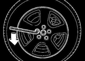
The bed cover can be removed and reinstalled as de- sired. (cid:84) Removal 1. Open the front section of the cover. (Refer to “Opening and closing the hard bed cover” in this sec- tion.) 2. Take out the wheel nut wrench from the tool bag. (Refer to “Jack and tools” section in chapter 9.)
Interior and exterior equipments
ly locked. If this does not lock the cover, release it from a slightly higher position. Do not push the cover forcibly to lock it.
(cid:132) Removal and installation of the hard
bed cover
UB6075BA
1) Brackets
(cid:121) When removing the bed cover, never remove the brackets shown in the above drawing.
6-32
Interior and exterior equipments
1) Bolts
UB6069BA
UB6070BA
3. Remove the two bolts shown in the above drawing using the wheel nut wrench.
– CONTINUED – 6-33
Interior and exterior equipments
UB6071BA
UB6072BA
1) Bolt hole
2. Position the cover so that the bolt holes on its bracket are aligned with those on the cargo bed.
4. Fold up the front and rear sections of the cover. Re- move the cover by holding it (by two or more adults) and place it in a safe location. 5. Put the wheel nut wrench back in the tool bag. (Re- fer to “Jack and tools” section in chapter 9.) (cid:84) Installation 1. Fold up the front and rear sections of the cover. Lift the cover (by two or more adults) and slowly place it on the cargo bed.
6-34
Interior and exterior equipments
UB6073BA
UB6074BA
3. Tighten the two bolts shown in the above drawing by hand and confirm that the hard bed cover is mount- ed correctly. 4. Take out the wheel nut wrench from the tool bag. (Refer to “Jack and tools” section in chapter 9.)
5. Tighten the bolts using the wheel nut wrench. The torque for tightening the bolts is 37 to 66 lbf·ft (50 to 90
N·m, 5 to 9 kgf·m). This torque is equivalent to apply- ing approximately 39 to 69 lbs (18 to 32 kg) at the top of the wheel nut wrench provided with your vehicle. 6. Close the front and rear sections of the cover. (Re- fer to “Opening and closing the hard bed cover” in this section.) 7. Put the wheel nut wrench back in the tool bag. (Re- fer to “Jack and tools” section in chapter 9.)– CONTINUED – 6-35
Interior and exterior equipments
Roof rail and crossbar
(cid:121) For cargo carrying purposes, the roof rail must be used together with a roof crossbar kit and the appropriate carrying attachment. The roof rail must never be used alone to carry car- go. Otherwise, damage to the roof or paint or a dangerous road hazard due to loss of cargo could result. (cid:121) When using the roof crossbar kit, make sure that the total weight of the crossbars, carrying attachment and cargo does not exceed the maximum load limit. Overloading may cause damage to the vehicle and create a safety haz- ard.
6-36
UB8037BB
1) Crossbar kit
The roof rail is not designed to carry cargo by itself. Cargo can be carried after securing the roof crossbar kit to the roof rail and installing the appropriate carry- ing attachment. When installing the roof crossbar kit, follow the manufacturer’s instructions. When you carry cargo on the roof using the roof cross- bar kit and a carrying attachment, never exceed the maximum load limit explained in the following. You should also be careful that your vehicle does not ex- ceed the Gross Vehicle Weight Rating (GVWR) and front and rear Gross Axle Weight Rating (GAWR). See the “Loading your vehicle” section in chapter 8 for in-
formation on loading cargo into or onto your vehicle. The maximum load limit of the cargo, crossbars and carrying attachment must not exceed 100 lbs (45 kg). Place the heaviest load at the bottom, nearest the roof, and evenly distribute the cargo. Always properly secure all cargo.
(cid:132) Installing carrying attachments on the
crossbars
When installing any carrying attachment such as a bike carrier, ski carrier, kayak carrier, cargo basket, etc. on the crossbars, follow the manufacturer’s in- structions and make sure that the attachment is se- curely fixed to the crossbars. Use only attachments designed specifically for the crossbars. A set of the crossbars is designed to carry loads (cargo and at- tachment) of not more than 100 lbs (45 kg). Before operating the vehicle, make sure that the cargo is properly secured on the attachment. NOTE Remember that the vehicle’s center of gravity is al- tered with the weight of the load on the roof, thus affecting the driving characteristics. Drive carefully. Avoid rapid starts, hard cornering and abrupt stops. Crosswind effects will be in- creased.
Interior and exterior equipments
(cid:132) Removal and installation of the cross-
bars
Do not carry cargo on the roof when the cross- bars are removed. Luggage on the roof will be thrown forward or backward in sudden stops or rapid accelerations, resulting in a dangerous road hazard.
The crossbars can be removed when you do not use the roof to carry cargo.
– CONTINUED – 6-37
Interior and exterior equipments
(cid:84) To remove the crossbar
6-38
1. Loosen and remove the T-30 torx® head screw from the side of each crossbar end support. 2. Move the end support and inner clamp to unhook each side of the crossbar from the roof rail. 3. Carefully raise the crossbar from roof rails. NOTE It may be necessary to move the Front crossbar rearward, near the center of the roof rail for easier removal. Use care not to cross-thread the screw in the insert if it has been removed. (cid:84) To install the crossbar NOTE Both Crossbars have a label indicating the direc- tion of mount. If they are not present, orient with the larger section of the Crossbar towards the front of vehicle (see below). The Front Crossbar also has a MAXIMUM LOAD Label affixed to it.
UB6047BA
UB6048BA
Interior and exterior equipments
Front crossbar: Front crossbar has 100 LBS. Load Label on left hand side.
1) Front 2) Rear 3) Crossbar (section)
UB6055BB
1) Load label
UB6051BB
– CONTINUED – 6-39
Interior and exterior equipments
7 in (180 mm)
UB6052BB
1. Before placing the crossbar on the roof rails, make sure that the T-30 torx® head screw is fully loosened from each end support. 2. Spread the inner clamp and the end support as far apart as possible. 3. With the front direction arrow label on the top right side of the crossbar pointing toward the front of the ve- hicle, carefully place the crossbar across the top of the vehicle so that the crossbar end supports rest on the top of the roof rails 7 inches (180 mm) rearward in the front radius of the roof rail. 4. Move the end support and inner clamp to hook un- der the end of the roof rail on both sides and loosely assemble the T-30 torx® head screw with the tool pro-
6-40
vided into the threaded insert in the inner clamp on each end of the crossbar. NOTE It may be necessary to start the inner clamp and end support at the center of the roof rail for easier installation, then move the crossbar forward. Use care not to cross-thread the screw in the insert if it has been removed.
UB6053BA
5. Adjust the alignment of the crossbar on the roof rails, and if available, use a T-30 torx® bit and torque wrench and tighten the T-30 torx® head screws to 30
to 35 lbf·in (3.4 to 4.0 N·m, 0.35 to 0.41 kgf·m) of torque (or tighten securely with the torx® wrench pro-vided). Rear crossbar:
0 in
(0 mm)
Interior and exterior equipments
UB6049BB
UB6050BA
Install the rear crossbar in the same manner as the front crossbar. NOTE (cid:121) The rear crossbar should be positioned just in front of the rear radius in the roof rail. (cid:121) Before each use of the roof crossbar, make sure the four T-30 crossbar clamp screws have been checked, and retightened if necessary to 35 lbf·in (4.0 N·m, 0.41 kgf·m), as outlined in Step #5 above.
– CONTINUED – 6-41
Interior and exterior equipments
Sport activity lights (if equipped)
operated on public roads. (cid:121) In most states, the sport activity lights may not be operated when the vehicle is in motion on a public road.
UB6041BB
1) Indicator light
The sport activity lights will operate only when the parking brake is engaged. Push the “SPORT LIGHTS” switch to turn the sport activity lights on. Press the switch again to turn them off. The indicator light located on the switch will illuminate when the sport activity lights are on. NOTE (cid:121) In most states, the sport activity lights must have stone shields installed when the vehicle is
6-42
UB3019AA
The sport activity lights mount to the vehicle front cross bar. The sport activity lights cross bar wire har- ness connects to the roof wire harness and then to the vehicle’s electrical system. A tool is provided which will activate the sport activity lights’ positioning to be modified, so that each lamp can be aimed or rotated. The lamps can be mounted in two positions, upright (normal) or forward (down- ward). The lamps should be rotated to the forward
Interior and exterior equipments
(downward) position when washing your vehicle. If you choose to remove sport activity lights, the follow- ing sequence should be utilized: 1. Disconnect the roof harness from the cross bar har- ness connector. 2. Attach the water proof connector cap to the roof harness connector. 3. Care should be used when removing or installing this electrical product.
– CONTINUED – 6-43
Fuel ................................................................ Fuel requirements ............................................. Fuel filler door and cap .................................... State emission testing (U.S. only) ...............