- Download PDF Manual
-
load) must never exceed the maximum weight shown in the following table.
8-26
Model
Conditions
MT models When towing a trailer with-
out brakes.
When towing a trailer with brakes.
AT models When towing a trailer with-
out brakes.
When towing a trailer with brakes.
When towing a trailer on a long uphill grade continu- ously for over 5 miles (8 km) with an outside temperature of 104°F (40°C) or above.
Maximum total trailer
weight
1,000 lbs (453 kg)
2,400 lbs (1,087 kg)
1,000 lbs (453 kg)
2,400 lbs (1,087 kg)
1,200 lbs (543 kg)
(cid:84) Gross Vehicle Weight (GVW) and Gross Vehicle
Weight Rating (GVWR)
Driving tips
UB8038BA
GVWR is shown on the certification label located on the driver’s door of your vehicle.
UB8043BA
Gross Vehicle Weight
The Gross Vehicle Weight (GVW) must never exceed the Gross Vehicle Weight Rating (GVWR). Gross Vehicle Weight (GVW) is the combined total of the weight of the vehicle, driver, passengers, luggage, trailer hitch, trailer tongue load and any other optional equipment installed on your vehicle. Therefore, the GVW changes depending on the situation. Determine the GVW each time before going on a trip by putting your vehicle and trailer on a vehicle scale.
– CONTINUED – 8-27
Driving tips
(cid:84) Gross Axle Weight (GAW) and Gross Axle
Weight Rating (GAWR)
UB8039BA
Gross Axle Weight
The total weight applied to each axle (GAW) must nev- er exceed the Gross Axle Weight Rating (GAWR). The front and rear GAWs can be adjusted by relocating passengers and luggage inside the vehicle.
UB8043BA
The front and rear GAWR are also shown on the cer- tification label. To check both GVWR and GAWR and to confirm that the total weight and weight distribution are within safe driving limits, you should have your vehicle and trailer weighed at a commercial weighing station. Be sure that all cargo is firmly secured to prevent a change in weight distribution while driving.
8-28
(cid:84) Tongue load
Driving tips
Ensure that the trailer tongue load is from 8 to 11 per- cent of the total trailer weight and does not exceed the maximum value of 200 lbs (90 kg).
Tongue load
HS8019AA
If the trailer is loaded with more weight in the back of trailer’s axle than in the front, the load is taken off the rear axle of the towing vehicle. This may cause the rear wheels to skid, espe- cially during braking or when vehicle speed is reduced during cornering, resulting in over- steer, spin out and/or jackknifing.
UB8040BB
1) Jack 2) Bathroom scale
The tongue load can be weighed with a bathroom scale as shown in the following illustration. When weighing the tongue load, be sure to position the tow- ing coupler at the height at which it would be during ac- tual towing, using a jack as shown.
– CONTINUED – 8-29
Driving tips
60%
40%
50% 50%
HS8021BB
F: Front
The tongue load can be adjusted by proper distribution of the load in the trailer. Never load the trailer with more weight in the back than in the front; approximate- ly 60 percent of the trailer load should be in the front and approximately 40 percent in the rear. Also, distrib- ute the load as evenly as possible on both the left and right sides. Be sure that all cargo is firmly secured to prevent a change in weight distribution while driving.
8-30
(cid:132) Trailer hitches
Never drill the frame or under-body of your ve- hicle to install a commercial trailer hitch. If you do, dangerous exhaust gas, water or mud may enter the passenger compartment through the drilled hole. Exhaust gas contains carbon mon- oxide, a colorless and odorless gas which is dangerous, or even lethal, if inhaled. Also, drill- ing the frame or under-body of your vehicle could cause deterioration of strength of your vehicle and cause corrosion around the drilled hole.
(cid:121) Do not modify the vehicle exhaust system, brake system, or other systems when installing a hitch or other trailer towing equipment. (cid:121) Do not use axle-mounted hitches as they can cause damage to the axle housing, wheel bear- ings, wheels or tires.
The use of a genuine SUBARU trailer hitch is recom-
mended. A genuine SUBARU hitch is available from your SUBARU dealer. If use of a non-genuine hitch is unavoidable, be sure the hitch is suited to your vehicle and trailer. Consult with a professional hitch supplier to assist you in choosing an appropriate hitch for your vehicle. Be sure to follow all of the hitch manufacturer’s instructions for installation and use. Never use a hitch that mounts only to the rear bumper. The bumper is not designed to handle that type of load. For all types of hitches, regularly check that the hitch mounting bolts and nuts are tight.
(cid:132) Connecting a trailer (cid:84) Trailer brakes
(cid:121) Adequate size trailer brakes are required when the trailer and its cargo exceed 1,000 lbs (453 kg) total weight. (cid:121) Do not directly connect your trailer’s hydrau- lic brake system to the hydraulic brake system in your vehicle. Direct connection would cause the vehicle’s brake performance to deteriorate
Driving tips
and could lead to an accident.
If your trailer’s total weight (trailer weight plus its cargo weight) exceeds 1,000 lbs (453 kg), the trailer is re- quired to be equipped with its own brake system. Elec- tric brakes or surge brakes are recommended, and must be installed properly. Check that your trailer’s brakes conform with Federal, state/province and/or other applicable regulations. Your SUBARU’s brake system is not designed to be tapped into the trailer’s hydraulic brake system. Please ask your SUBARU dealer and professional trailer supplier for more infor- mation about the trailer’s brake system. (cid:84) Trailer safety chains
Always use safety chains between your vehicle and the trailer. Towing trailer without safety chains could create a traffic safety hazard if the trailer separates from the hitch due to coupling damage or hitch ball damage.
In case the trailer hitch connector or hitch ball should break or become disconnected, the trailer could get
– CONTINUED – 8-31
Driving tips
loose and create a traffic safety hazard. For safety, always connect the towing vehicle and trailer with trailer safety chains. Pass the chains cross- ing each other under the trailer tongue to prevent the trailer from dropping onto the ground in case the trailer tongue should disconnect from the hitch ball. Allow sufficient slack in the chains taking tight-turn situations into account; however, be careful not to let them drag on the ground. For more information about the safety chain connec- tion, refer to the instructions for your hitch and trailer. (cid:84) Side mirrors
standard side mirrors provide a good rearward field of view without significant blind spots. If significant blind spots occur with the vehicle’s standard side mirrors, use towing mirrors that conform with Federal, state/ province and/or other applicable regulations. (cid:84) Trailer lights
Direct splicing or other improper connection of trailer lights may damage your vehicle’s electri- cal system and cause a malfunction of your ve- hicle’s lighting system.
Connection of trailer lights to your vehicle’s electrical system requires modifications to the vehicle’s lighting circuit to increase its capacity and accommodate wir- ing changes. To ensure the trailer lights are connected properly, please consult your SUBARU dealer. Check for proper operation of the turn signals, the brake lights and parking lights each time you hitch up. (cid:84) Tires
After hitching a trailer to your vehicle, check that the
Never tow a trailer when the temporary spare
UB8041BA
8-32
tire is used. The temporary spare tire is not de- signed to sustain the towing load. Use of the temporary spare tire when towing can result in failure of the spare tire and/or less stability of the vehicle.
Make sure that all the tires on your vehicle are properly inflated. The recommended cold tire pressure is shown on the vehicle placard attached to the driver’s side door jamb. Trailer tire condition, size, load rating and proper infla- tion pressure should be in accordance with the trailer manufacturer’s specifications. In the event your vehicle gets a flat tire when towing a trailer, ask a commercial road service to repair the flat tire. If you carry a regular size spare tire in your vehicle or trailer as a precaution against getting a flat tire, be sure that the spare tire is firmly secured.
Driving tips
(cid:132) Trailer towing tips
(cid:121) Never exceed 45 mph (72 km/h) when towing a trailer in hilly country on hot days. (cid:121) When towing a trailer, steering, stability, stopping distance and braking performance will be different from normal operation. For safety’s sake, you should employ extra caution when towing a trailer and you should never speed. You should also keep the following tips in mind:
(cid:84) Before starting out on a trip (cid:121) Check that the vehicle and vehicle-to-hitch mount- ing are in good condition. If any problems are appar- ent, do not tow the trailer. (cid:121) Check that the vehicle sits horizontally with the trail- er attached. If the vehicle is tipped sharply up at the front and down at the rear, check the total trailer weight, GVW, GAWs and tongue load again, then con- firm that the load and its distribution are acceptable. (cid:121) Check that the tire pressures are correct. (cid:121) Check that the vehicle and trailer are connected properly. Confirm that.
– CONTINUED – 8-33
Driving tips
– the trailer tongue is connected properly to the hitch ball. – the trailer lights connector is connected properly and trailer’s brake lights illuminate when the vehi- cle’s brake pedal is pressed, and that the trailer’s turn signal lights flash when the vehicle’s turn signal lever is operated. – the safety chains are connected properly. – all cargo in the trailer is secured safety in position. – the side mirrors provide a good rearward field of view without a significant blind spot.
(cid:121) Sufficient time should be taken to learn the “feel” of the vehicle/trailer combination before starting out on a trip. In an area free of traffic, practice turning, stopping and backing up. (cid:84) Driving with a trailer (cid:121) You should allow for considerably more stopping distance when towing a trailer. Avoid sudden braking because it may result in skidding or jackknifing and loss of control. (cid:121) Avoid abrupt starts and sudden accelerations. If your vehicle has a manual transmission, always start out in first gear and release the clutch at moderate en- gine revolution. (cid:121) Avoid uneven steering, sharp turns and rapid lane changes. (cid:121) Slow down before turning. Make a longer than nor-
8-34
mal turning radius because the trailer wheels will be closer than the vehicle wheels to the inside of the turn. In a tight turn, the trailer could hit your vehicle. (cid:121) Crosswinds will adversely affect the handling of your vehicle and trailer, causing sway. Crosswinds can be due to weather conditions or the passing of large trucks or buses. If swaying occurs, firmly grip the steering wheel and slow down immediately but gradu- ally. (cid:121) When passing other vehicles, considerable dis- tance is required because of the added weight and length caused by attaching the trailer to your vehicle.
1) Left turn 2) Right turn
HS8023BB
(cid:121) Backing up with a trailer is difficult and takes prac- tice. When backing up with a trailer, never accelerate or steer rapidly. When turning back, grip the bottom of the steering wheel with one hand and turn it to the left for a left turn, and turn it to the right for a right turn. (cid:121) If the ABS warning light illuminates while the vehicle is in motion, stop towing the trailer and have repairs performed immediately by the nearest SUBARU deal- er. (cid:84) Driving on grades (cid:121) Before going down a steep hill, slow down and shift into lower gear (if necessary, use 1st gear) in order to utilize the engine braking effect and prevent overheat- ing of your vehicle’s brakes. Do not make sudden downshifts. (cid:121) When driving uphill in hot weather, the air condition- er may turn off automatically to protect the engine from overheating. (cid:121) When driving uphill in hot weather, pay attention to the water temperature gauge pointer (for all vehicles) and AT OIL TEMP warning light (for AT vehicles) since the engine and transmission are relatively prone to overheating under these conditions. If the water tem- perature gauge pointer approaches the OVERHEAT zone or the AT OIL TEMP warning light illuminates, immediately switch off the air conditioner and stop the vehicle at the nearest safe place. Refer to the “Engine
Driving tips
overheating” section in chapter 9, and “Warning and indicator lights” section in chapter 3. NOTE (Turbo models only) In a vehicle that has an automatic transmission, the engine is less likely to overheat with the “D” range selected than it is with the manual mode se- lected. (cid:121) If your vehicle has an automatic transmission, avoid using the accelerator pedal to stay stationary on an uphill slope instead of using the parking brake or foot brake. That may cause the transmission fluid to over- heat. (cid:121) Non-turbo models only: If your vehicle has an auto- matic transmission, place the selector lever as follows: Uphill slopes: “D” position Downhill slopes: A low-speed gear position to use en- gine braking (cid:84) Parking on a grade Always block the wheels under both vehicle and trailer when parking. Apply the parking brake firmly. You should not park on a hill or slope. But if parking on a hill or slope cannot be avoided, you should take the following steps: 1. Apply the brakes and hold the pedal down. 2. Have someone place wheel blocks under both the
– CONTINUED – 8-35
Driving tips
vehicle and trailer wheels. 3. When the wheel blocks are in place, release the regular brakes slowly until the blocks absorb the load. 4. Apply the regular brakes and then apply the park- ing brake; slowly release the regular brakes. 5. Shift into 1st or reverse gear (manual transmission) or “P” (automatic transmission) and shut off the en- gine.
8-36
In case of emergency
Using the temporary spare tire ........................
If you park your vehicle in an emergency .. Jack and tools ............................................... Location of jack and tools ............................... Removing jack and tool bag ............................ Restoring jack and tools .................................. Spare tire ....................................................... Removing the spare tire ................................... Re-storage of spare tire ...................................
9-2
9-3
9-3
9-3
9-5
9-7
9-7
9-9
Temporary spare tire .................................... 9-10
9-10
Flat tires ......................................................... 9-12
9-12
Jump starting ................................................ 9-18
9-19
Engine overheating ....................................... 9-21
9-21
9-21
Towing ........................................................... 9-22
9-23
9-27
9-27Towing and tie-down hooks ............................ Using a flat-bed truck ....................................... Towing with all wheels on the ground ............
compartment .................................................. compartment ..................................................
If steam is coming from the engine If no steam is coming from the engine
Changing a flat tire ...........................................
How to jump start .............................................
9-1
In case of emergency
In case of emergency
If you park your vehicle in an emer- gency
NOTE When the hazard warning flasher is on, the turn signals do not work.
UB8002BA
The hazard warning flasher should be used in day or night to warn other drivers when you have to park your vehicle under emergency conditions. Avoid stopping on the road. It is best to safely pull off the road if a problem occurs. The hazard warning flasher can be activated regard- less of the ignition switch position. Turn on the hazard warning by pushing the hazard warning flasher switch. Turn it off by pushing the switch again.
9-2
Jack and tools The jack supplied with the vehicle is designed only for changing a tire. Before using the jack, see the “Flat tires” section in this chapter for instructions and precautions.
(cid:132) Location of jack and tools
The jack and tool bag are located in the left side rear quarter pocket at the back side of the rear seatback.
UB9091BA
In case of emergency
900276
A wheel nut wrench, jack drive tube, tire holding rod, tire holding retainer, screwdriver and two belts are in- cluded in the tool bag.
(cid:132) Removing jack and tool bag
Before folding down the seatback, check that there is nothing in the seatback pocket. If there is something in the pocket, it could be damaged or cause damage to the seatback and rear cen- ter console when the seatback is folded.
– CONTINUED – 9-3
In case of emergency
1) Red A) LOCK B) UNLOCK
UB1109BB
UB9074BA
2. Open the left-hand pocket lid by turning the knob. 3. Take the tool bag out of the pocket.
1. Pull the rear seatback locks up and fold down the rear seatback to gain access to the rear quarter pock- ets at both sides.
9-4
In case of emergency
(cid:132) Restoring jack and tools
UB9075BA
4. Loosen the jack holding screw by turning counter- clockwise and remove the jack from the pocket. NOTE (cid:121) Be careful not to lose the jack holding screw af- ter removing it. (cid:121) Make sure the jack is well lubricated before us- ing it.
900277
1. Strap the wheel nut wrench, jack drive tube, and tire holding rod together using the two belts, then re- turn them to the tool bag together with the other tools. 2. Contract the jack by turning the jack screw counter- clockwise to the end.
– CONTINUED – 9-5
4. Securely fix the jack with the jack holding screw by turning it clockwise. 5. Install the left-hand pocket lid and lock it by turning the knob. NOTE Confirm no looseness exists after securing the jack. Looseness may cause a rattle while the vehi- cle is moving.
After the jack and the tool bag have been re- stored in the rear quarter pocket, make sure that the rear seatback has been securely locked. When securely locked, the red marks on the locking knobs are no longer visible.
In case of emergency
3. Place the jack onto the bracket in the pocket.
UB9076BA
UB9075CA
9-6
Spare tire
In case of emergency
(cid:132) Removing the spare tire 1. Take the wheel nut wrench out of the tool bag. Re- fer to the “Jack and tools” section in this chapter for its storage location.
UB9053BA
The spare tire is stored in the spare tire holder located under the rear of the cargo bed. The spare tire holder has a hoist mechanism that can lower and raise the spare tire easily. The spare tire holder is designed to carry only the temporary spare tire that comes with your vehicle. Before using the temporary spare tire, see the “Tem- porary spare tire” section in this chapter for instruc- tions and precautions.
UB9054BA
2. Open the tailgate and remove the rubber cap from the cargo bed. Pull up the “RELEASE” portion of the cap when removing it. 3. Locate the hex-headed hoist shaft end inside the hole.
– CONTINUED – 9-7
In case of emergency
UB9055BA
UB9056AA
4. Turn the hoist shaft end counterclockwise with the wheel nut wrench until the temporary spare tire is on the ground with enough cable slack to allow you to pull it out from under the vehicle.
Do not put your fingers into the center hole of the temporary spare tire while you pulling it out, because they might be pinched in between the wheel and the retainer.
5. Tilt the retainer at the end of the cable and pull it through the center of the temporary spare tire. 6. After the temporary spare tire is removed from the cable, the cable must be wound up completely by turn- ing the hoist nut shaft clockwise until you hear a click- ing sound. Also visually inspect the cable to make cer- tain that there is no longer any slack present.
(cid:121) When using the spare tire hoist: After the temporary spare tire is removed from the cable, wind the cable up completely until the retainer at end of the cable sits against the
9-8
underside of the vehicle. Driving with the cable not retracted fully could result in damage to the adjacent under floor parts and lead to a serious accident. (cid:121) The spare tire holder is designed to carry only the smaller temporary spare tire. Never store a full size tire (flat or otherwise) in the spare tire holder. Doing so can result in dam- age to adjacent under floor parts and can lead to a serious accident.
When using the spare tire hoist: Do not use air tools or power tools to turn the spare tire hoist shaft end. If you do, it could re- sult in severe mechanical damage to the spare tire hoist.
(cid:132) Re-storage of spare tire 1. Turn the spare tire hoist shaft end counterclock- wise with the wheel nut wrench to loosen the cable sufficiently enough to allow the cable end retainer go through center hole of the temporary spare tire. 2. Insert the retainer through the center hole of the
In case of emergency
temporary tire (with the outside of the tire facing up). 3. Turn the hoist shaft end clockwise with the wheel nut wrench to wind the cable up completely until you hear a few clicking sounds. Confirm that the temporary spare tire holding cable has been wound up complete- ly by shaking the temporary tire.
If the temporary spare tire is not stored secure- ly, it could damage adjacent areas of the vehi- cle and make an abnormal noise.
4. Put the rubber cap on the hoist shaft end hole. 5. Place the wheel nut wrench back into the tool bag and store the jack and tool bag in their storage loca- tions.
– CONTINUED – 9-9
Check the inflation pressure of the temporary spare tire periodically to keep the tire ready for use. The cor- rect pressure is 60 psi (420 kPa, 4.2 kgf/cm2). When using the temporary spare tire, note the follow- ing. (cid:121) Do not exceed 50 mph (80 km/h). (cid:121) Do not put a tire chain on the temporary spare tire. Because of the smaller tire size, a tire chain will not fit properly. (cid:121) Do not use two or more temporary spare tires at the same time. (cid:121) Do not drive over obstacles. This tire has a smaller diameter, so road clearance is reduced.
In case of emergency
Temporary spare tire (cid:132) Using the temporary spare tire
Never tow a trailer when the temporary spare tire is used. The temporary spare tire is not de- signed to sustain the towing load. Use of the temporary spare tire when towing can result in failure of the spare tire and/or less stability of the vehicle and may lead to an accident.
Never use any temporary spare tire other than the original. Using other sizes may result in se- vere mechanical damage to the drive train of your vehicle.
The temporary spare tire is smaller and lighter than a conventional tire and is designed for emergency use only. Remove the temporary spare tire and re-install the conventional tire as soon as possible because the spare tire is designed only for temporary use.
9-10
In case of emergency
UG0106
1) Tread wear indicator bar 2) Indicator location mark
(cid:121) When the wear indicator appears on the tread, re- place the tire. (cid:121) The temporary spare tire must be used only on a rear wheel. If a front wheel tire gets punctured, replace the wheel with a rear wheel and install the temporary spare tire in place of the removed rear wheel.
UB8003BC
1) Spare fuse 2) FWD connector NOTE [Automatic transmission vehicles except Turbo vehicle] Before driving your vehicle with the tem- porary spare tire, put a spare fuse inside the FWD connector located in the engine compartment and confirm that the AWD warning light comes on. The All-Wheel Drive capability of the vehicle has now been deactivated. After re-installing the conven- tional tire, remove the spare fuse from the FWD connector in order to reactivate All-Wheel Drive.
– CONTINUED – 9-11
In case of emergency
Flat tires If you get a flat tire while driving, never brake sudden- ly; keep driving straight ahead while gradually reduc- ing speed. Then slowly pull off the road to a safe place.
(cid:132) Changing a flat tire
(cid:121) Do not jack up the vehicle on an incline or a loose road surface. The jack can come out of the jacking point or sink into the ground and this can result in a serious accident. (cid:121) Use only the jack provided with your vehicle. The jack supplied with the vehicle is designed only for changing a tire. Never get under the ve- hicle while supporting the vehicle with this jack. (cid:121) Always turn off the engine before raising the flat tire off the ground using the jack. Never swing or push the vehicle supported with the jack. The jack can come out of the jacking point due to a jolt and this can result in a serious ac- cident. (cid:121) Never place a tire or tire changing tools in the passenger changing
compartment
after
9-12
wheels. In a sudden stop or collision, loose equipment could strike occupants and cause injury. Store the tire and all tools in the proper place.
1. Park on a hard, level surface, whenever possible, then stop the engine. 2. Set the parking brake securely and shift a manual transmission vehicle into reverse or an automatic transmission vehicle into the “P” (Park) position. 3. Turn on the hazard warning flasher and have ev- eryone get out of the vehicle.
4. Put wheel blocks at the front and rear of the tire di-
HS9003BA
agonally opposite the flat tire. 5. Take out the spare tire, jack, and wheel nut wrench. Refer to the sections “Spare tire” and “Jack and tools” in this chapter for their location, instructions and pre- cautions. After the spare tire is removed from the spare tire hold- er, the cable must be wound up completely by turning the hoist nut shaft clockwise until you hear a clicking sound. Also visually inspect the cable to make certain that there is no longer any slack present. (cid:84) Removing the flat tire and installing the spare
tire
In case of emergency
but do not remove the nuts.
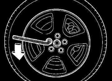
1. Loosen the wheel nuts using the wheel nut wrench
US9008BA
UB9088BB
1) Jack up point mark
2. Place the jack under the side sill at the front or rear jack-up point closest to the flat tire. Jack-up points are
– CONTINUED – 9-13
In case of emergency
indicated by arrow marks on the side of the side sill skirt.
3. Turn the jackscrew by hand until the groove of the jack head engages firmly into the jack-up point.
UB9089BA
UB9060BA
4. Insert the jack drive tube into the jackscrew and at- tach the wheel nut wrench into the jack drive tube, and turn the handle until the tire clears the ground. Do not raise the vehicle higher than necessary. 5. Remove the wheel nuts and the flat tire.
9-14
In case of emergency
surface of the wheel and hub with a cloth. 7. Put on the spare tire. Replace the wheel nuts. Tighten them by hand.
Do not use oil or grease on the wheel studs or nuts when the spare tire is installed. This could cause the nuts to become loose and lead to an accident.
HS9011BA
8. Turn the jack handle counterclockwise to lower the vehicle.
6. Before putting the spare tire on, clean the mounting
UB9220BA
UB9078BB
– CONTINUED – 9-15
In case of emergency
bag.
9. Use the wheel nut wrench to securely tighten the wheel nuts to the specified torque, following the tight- ening order in the illustration. The torque for tightening the nuts is 74 to 89 lbf·ft (100 to 120 N·m, 10 to 12
kgf·m). This torque is equivalent to applying approxi- mately 88 to 110 lbs (40 to 50 kg) at the top of the wheel nut wrench provided with your vehicle. Never use your foot on the wheel nut wrench or a pipe exten- sion on the wrench because you may exceed the specified torque. Have the wheel nut torque checked at the nearest automotive service facility. (cid:84) Storage of the flat tire2. Remove the rubber cap from the cargo bed. Store the rubber cap in a safe place. Pay attention not to lose the rubber cap after removal.
UB9077BA
(cid:121) Secure the flat tire in the cargo bed (with the outer side of the wheel facing up) by using the designated tire holding rod and retainer. If the flat tire is not properly secured, it may fall out and create a dangerous road hazard that could lead to a serious accident. (cid:121) Do not store the flat tire under the floor. Do- ing so could damage the underside of the vehi- cle.
1. Take the tire holding rod and retainer out of the tool
9-16
In case of emergency
UB9062BB
UB9063BA
1) Holding rod 2) Retainer
3. Place the flat tire in the cargo bed with the outer side of the wheel facing up. For an aluminum wheel, remove the center cap before placing it in the cargo bed. 4. Place the retainer on the center hole of the wheel as illustrated and put the tire holding rod into the re- tainer. If the flat tire is separated from its wheel completely, the retailer should be placed upside down on the wheel.
5. Secure the flat tire by tightening the tire holding rod. The tire holding rod and retainer are designed solely to secure a flat tire in emergency. Do not use them for another purpose such as securing cargo. 6. Store the jack and wheel nut wrench in their stor- age locations. 7. Put the rubber cap back in its original position after everything has been restored. (cid:84) Driving with the temporary spare tire Your spare tire is only a temporary spare which is de- signed for temporary emergency use only. When driv- ing with the temporary spare tire, follow the instruc- – CONTINUED – 9-17
In case of emergency
tions and precautions described in the “Temporary spare tire” section in this chapter. Replace the temporary spare tire with a conventional tire as soon as you can.
Jump starting
(cid:121) Battery fluid is SULFURIC ACID. Do not let it come in contact with the eyes, skin, clothing or the vehicle. If battery fluid gets on you, thoroughly flush the exposed area with water immediately. Get med- ical help if the fluid has entered your eyes. If battery fluid is accidentally swallowed, imme- diately drink a large amount of milk or water, and obtain immediate medical help. Keep everyone including children away from the battery. (cid:121) The gas generated by a battery explodes if a flame or spark is brought near it. Do not smoke or light a match while jump starting. (cid:121) Never attempt jump starting if the discharged battery is frozen. It could cause the battery to burst or explode. (cid:121) Whenever working on or around a battery, al- ways wear suitable eye protectors, and remove metal objects such as rings, bands or other metal jewelry. (cid:121) Be sure the jumper cables and clamps on them do not have loose or missing insulation.
9-18
Do not jump start unless cables in suitable con- dition are available. (cid:121) A running engine can be dangerous. Keep your fingers, hands, clothing, hair and tools away from the cooling fan, belts and any other moving engine parts. Removing rings, watches and ties is advisable. (cid:121) Jump starting is dangerous if it done incor- rectly. If you are unsure about the proper proce- dure for jump starting, consult a competent me- chanic.
When your vehicle does not start due to a run down (discharged) battery, the vehicle may be jump started by connecting your battery to another battery (called the booster battery) with jumper cables.
(cid:132) How to jump start 1. Make sure the booster battery is 12 volts and the negative terminal is grounded. 2. If the booster battery is in another vehicle, do not let the two vehicles touch. 3. Turn off all unnecessary lights and accessories. 4. Connect the jumper cables exactly in the sequence illustrated.
In case of emergency
– CONTINUED – 9-19
In case of emergency
1)Connect one jumper cable to the positive (+) terminal on the dis- charged battery. 2)Connect the other end of the jumper cable to the positive (+) ter- minal of the booster battery. 3)Connect one end of the other cable to the negative (–) terminal of the booster battery. 4)Connect the other end of the ca- ble to the engine lifting bracket. Make sure that the cables are not near any moving parts and that the cable clamps are not in contact with any other metal.
900275
1) Booster battery 2) Engine lifting bracket
9-20
5. Start the engine of the vehicle with the booster bat- tery and run it at moderate speed. Then start the en- gine of the vehicle that has the discharged battery. 6. When finished, carefully disconnect the cables in exactly the reverse order.
In case of emergency
Engine overheating
Never attempt to remove the radiator cap until the engine has been shut off and has fully cooled down. When the engine is hot, the cool- ant is under pressure. Removing the cap while the engine is still hot could release a spray of boiling hot coolant, which could burn you very seriously.
If the engine overheats, pull off the road safely and stop the vehicle in a safe place.
(cid:132) If steam is coming from the engine
compartment
Turn off the engine and get everyone away from the vehicle until it cools down.
(cid:132) If no steam is coming from the engine
compartment
1. Keep the engine running at idling speed. 2. Open the hood to ventilate the engine compart- ment.
– CONTINUED – 9-21
In case of emergency
Confirm that the cooling fan is turning. If the fan is not turning, immediately turn off the engine and contact your authorized dealer for repair. 3. After the engine coolant temperature has dropped, turn off the engine. If the temperature gauge stays at the overheated zone, turn off the engine. 4. After the engine has fully cooled down, check the coolant level in the reserve tank. If the coolant level is below the “MIN” mark, add cool- ant up to the “MAX” mark. 5. If there is no coolant in the reserve tank, add cool- ant to the reserve tank. Then remove the radiator cap and fill the radiator with coolant. If you remove the radiator cap from a hot radiator, first wrap a thick cloth around the radiator cap, then turn the cap counterclockwise slowly without pressing down until it stops. Release the pressure from the ra- diator. After the pressure has been fully released, re- move the cap by pressing down and turning it.
Towing
Never tow AWD vehicles (both AT and MT) with the front wheels raised off the ground while the rear wheels are on the ground, or with the rear wheels raised off the ground while the front wheels are on the ground. This will cause the vehicle to spin away due to the operation or de- terioration of the center differential.
9-22
If towing is necessary, it is best done by your SUBARU
UB9064BA
dealer or a commercial towing service. Observe the following procedures for safety.
(cid:132) Towing and tie-down hooks The towing hooks should be used only in an emergen- cy (e.g., to free a stuck vehicle from mud, sand or snow).
(cid:121) Use only specified towing hooks and tie- down hooks. Never use suspension parts or other parts of the body for towing or tie-down purposes. (cid:121) Never use the tie-down hook closest to the muffler under the vehicle for towing purposes. (cid:121) To prevent deformation to the front bumper and the towing hook, do not apply excessive lateral load to the towing hooks.
In case of emergency
1) Towing hook cover 2) Towing hook
UB9065BB
The front towing hook is located on the inside of the towing hook cover below the right-hand headlight.
– CONTINUED – 9-23
In case of emergency
UB9070BB
1) Tie-down hook
1) Tie-down hook 2) Towing and tie-down hook
UB9066CB
9-24
1
UB9010BB
Vehicle with trailer hitch (if equipped) 1) Tie-down hook
In case of emergency
(cid:84) Towing hook cover removal procedure The towing hook cover is secured by tabs that fit into corresponding slots in the vehicle body. To remove the cover:
1. Free the tabs on the towing hook cover by firmly pressing the point indicated by an arrow with the palm of your hand.
UB9083BA
– CONTINUED – 9-25
In case of emergency
(cid:84) Towing hook cover installation procedure
2. Pull off the towing hook cover.
UB9084BA
UB9069BA
To reinstall the towing hook cover, push it in on both sides while pushing it back to its original position. Make certain that the tabs at the end of the cover are securely inserted into the corresponding slots in the vehicle’s body.
9-26
(cid:132) Using a flat-bed truck
(cid:132) Towing with all wheels on the ground
In case of emergency
UB9072AA
UB9071AA
This is the best way to transport your vehicle. Use the following procedures to ensure safe transportation. 1. Shift the selector lever into the “P” position for au- tomatic transmission vehicles or “1st” for manual transmission vehicles. 2. Pull up the parking brake lever firmly. 3. Secure the vehicle onto the carrier properly with safety chains. Each safety chain should be equally tightened and care must be taken not to pull the chains so tightly that the suspension bottoms out.
(cid:121) Never turn the ignition switch to the “LOCK” position while the vehicle is being towed be- cause the steering wheel and the direction of the wheels will be locked. (cid:121) Remember that the brake booster and power steering do not function when the engine is not running. Because the engine is turned off, it will take greater effort to operate the brake pedal and steering wheel.
– CONTINUED – 9-27
In case of emergency
(cid:121) If transmission failure occurs, transport your vehicle on a flat-bed truck. (cid:121) Do not run the engine while the vehicle is be- ing towed using this method. Transmission damage could result if the vehicle is towed with the engine running. (cid:121) For vehicles with automatic transmission, the traveling speed must be limited to less than 20 mph (30 km/h) and the traveling distance to less than 31 miles (50 km). For greater speeds and distances, transport your vehicle on a flat- bed truck.
1. Check the transmission and differential oil levels and add oil to bring it to the upper level if necessary. 2. Release the parking brake and put the transmis- sion in neutral. 3. The ignition switch should be in the “ACC” position while the vehicle is being towed. 4. Take up slack in the towline slowly to prevent dam- age to the vehicle.
9-28
Appearance care
Most common causes of corrosion ................ To help prevent corrosion ...............................
Washing ............................................................. Waxing and polishing ....................................... Cleaning aluminum wheels .............................. Cleaning front fog light lens ............................
Exterior care .................................................. 10-2
10-2
10-3
10-4
10-4
Corrosion protection .................................... 10-5
10-5
10-5
Cleaning the interior ..................................... 10-6
10-6
10-7
10-7Seat fabric ......................................................... Leather seat materials ...................................... Synthetic leather upholstery ........................... Climate control panel, audio panel, instrument panel, console panel, switches, combination meter, and other plastic surfaces .................
10-7
10
10-1
Appearance care
Appearance careExterior care (cid:132) Washing
(cid:121) When washing the vehicle, the brakes may get wet. As a result, the brake stopping dis- tance will be longer. To dry the brakes, drive the vehicle at a safe speed while lightly pressing the brake pedal to heat up the brakes. (cid:121) Do not wash the engine compartment and ar- eas adjacent to it. If water enters the engine air intake, electrical parts or the power steering flu- id reservoir, it will cause engine trouble or faulty power steering respectively.
NOTE (cid:121) Before having your vehicle washed in an auto- matic car wash, retract the pillar mounted antenna or remove the roof mounted antenna to prevent it from being damaged. (cid:121) When having your vehicle washed in an auto- matic car wash, make sure beforehand that the car wash is of suitable type. The best way to preserve your vehicle’s beauty is fre-
10-2
quent washing. Wash the vehicle at least once a month to avoid contamination by road grime. Wash dirt off with a wet sponge and plenty of luke- warm or cold water. Do not wash the vehicle with hot water and in direct sunlight. Salt, chemicals, insects, tar, soot, tree sap, and bird droppings should be washed off by using a light deter- gent, as required. If you use a light detergent, make certain that it is a neutral detergent. Do not use strong soap or chemical detergents. All cleaning agents should be promptly flushed from the surface and not allowed to dry there. Rinse the vehicle thoroughly with plenty of lukewarm water. Wipe the remaining water off with a chamois or soft cloth. (cid:84) Washing the underbody Chemicals, salts and gravel used for deicing road sur- faces are extremely corrosive, accelerating the corro- sion of underbody components, such as the exhaust system, fuel and brake lines, brake cables, floor pan and fenders, and suspension. Thoroughly flush the underbody and inside of the fenders with lukewarm or cold water at frequent inter- vals to reduce the harmful effects of such agents. Mud and sand adhering to the underbody components may accelerate their corrosion.
After driving off-road or muddy or sandy roads, wash the mud and sand off the underbody. Carefully flush the suspension and axle parts, as they are particularly prone to mud and sand buildup. Do not use a sharp-edged tool to remove caked mud. NOTE Be careful not to damage brake hoses, sensor har- nesses, and other parts when washing suspen- sion components. (cid:84) Using a warm water washer (cid:121) Keep a good distance of 12 in (30 cm) or more be- tween the washer nozzle and the vehicle. (cid:121) Do not wash the same area continuously. (cid:121) If a stain will not come out easily, wash by hand. Some warm water washers are of the high tempera- ture, high pressure type, and they can damage or de- form the resin parts such as mouldings, or cause wa- ter to leak into the vehicle.
(cid:132) Waxing and polishing Always wash and dry the vehicle before waxing and polishing. Use a good quality polish and wax and apply them ac- cording to the manufacturer’s instructions. Wax or pol- ish when the painted surface is cool.
Appearance care
Be sure to polish and wax the chrome trim, as well as the painted surfaces. Loss of wax on a painted surface leads to loss of the original luster and also quickens the deterioration of the surface. It is recommended that a coat of wax be applied at least once a month, or whenever the surface no longer repels water. If the appearance of the paint has diminished to the point where the luster or tone cannot be restored, lightly polish the surface with a fine-grained com- pound. Never polish just the affected area, but include the surrounding area as well. Always polish in only one direction. A No. 2000 grain compound is recom- mended. Never use a coarse-grained compound. Coarser grained compounds have a smaller grain-size number and could damage the paint. After polishing with a compound, coat with wax to restore the original luster. Frequent polishing with a compound or an in- correct polishing technique will result in removing the paint layer and exposing the undercoat. When in doubt, it is always best to contact your SUBARU deal- er or an auto paint specialist. NOTE Be careful not to damage brake hoses, sensor har- nesses, and other parts when washing suspen- sion components.
– CONTINUED – 10-3
Appearance care
(cid:132) Cleaning aluminum wheels (cid:121) Promptly wipe the aluminum wheels clean of any kind of grime or agent. If dirt is left on too long, it may be difficult to clean off. (cid:121) Do not use soap containing grit to clean the wheels. Be sure to use a neutral cleaning agent, and later rinse thoroughly with water. Do not clean the wheels with a stiff brush or expose them to a high-speed washing device. (cid:121) Clean the vehicle (including the aluminum wheels) with water as soon as possible when it has been splashed with sea water, exposed to sea breezes, or driven on roads treated with salt or other agents.
(cid:132) Cleaning front fog light lens 1. Stop the vehicle in a safe place. 2. Stop the engine and turn off the front fog lights.
10-4
10(cid:31)
UBA017BB
1) Counter-clockwise 2) Light lens horizontal center line
3. Check that the front fog lights are not hot. Then, grasp the protector and turn it approximately 10° counter-clockwise. 4. Pull the protector off the front fog light. 5. Wash the lens with water. 6. Apply the protector to the lens at an angle of ap- proximately 10° from the front fog light’s horizontal center line. Then, turn the protector clockwise until it stops. Finally, check that the protector’s horizontal bars are parallel with the front fog light’s horizontal center line.
Corrosion protection Your SUBARU has been designed and built to resist corrosion. Special materials and protective finishes have been used on most parts of the vehicle to help maintain fine appearance, strength, and reliable oper- ation.
(cid:132) Most common causes of corrosion The most common causes of corrosion are: 1. The accumulation of moisture retaining dirt and de- bris in body panel sections, cavities, and other areas. 2. Damage to paint and other protective coatings caused by gravel and stone chips or minor accidents. Corrosion is accelerated on the vehicle when: 1. It is exposed to road salt or dust control chemicals, or used in coastal areas where there is more salt in the air, or in areas where there is considerable industrial pollution. 2. It is driven in areas of high humidity, especially when temperatures range just above freezing. 3. Dampness in certain parts of the vehicle remains for a long time, even though other parts of the vehicle may be dry. 4. High temperatures will cause corrosion to parts of the vehicle which cannot dry quickly due to lack of
Appearance care
proper ventilation.
(cid:132) To help prevent corrosion Wash the vehicle regularly to prevent corrosion of the body and suspension components. Also, wash the ve- hicle promptly after driving on any of the following sur- faces: (cid:121) roads that have been salted to prevent them from freezing in winter (cid:121) mud, sand, or gravel (cid:121) coastal roads After the winter has ended, it is recommended that the underbody be given a very thorough washing. Before the beginning of winter, check the condition of underbody components, such as the exhaust system, fuel and brake lines, brake cables, suspension, steer- ing system, floor pan, and fenders. If any of them are found to be rusted, they should be given an appropri- ate rust prevention treatment or should be replaced. Contact your SUBARU dealer to perform this kind of maintenance and treatment if you need assistance. Repair chips and scratches in the paint as soon as you find them. Check the interior of the vehicle for water and dirt ac-
– CONTINUED – 10-5
Appearance care
cumulation under the floor mats because that could cause corrosion. Occasionally check under the mats to make sure the area is dry. Keep your garage dry. Do not park your vehicle in a damp, poorly ventilated garage. In such a garage, cor- rosion can be caused by dampness. If you wash the vehicle in the garage or put the vehicle into the garage when wet or covered with snow, that can cause damp- ness. If your vehicle is operated in cold weather and/or in ar- eas where road salts and other corrosive materials are used, the door hinges and locks, and hood latch should be inspected and lubricated periodically.
10-6
Cleaning the interior Use a soft, damp cloth to clean the climate control panel, audio equipment, instrument panel, center con- sole, combination meter panel, and switches. (Do not use organic solvents.)
(cid:132) Seat fabric Remove loose dirt, dust or debris with a vacuum cleaner. If the dirt is caked on the fabric or hard to re- move with a vacuum cleaner, use a soft blush then vacuum it. Wipe the fabric surface with a tightly wrung cloth and dry the seat fabric thoroughly. If the fabric is still dirty, wipe using a solution of mild soap and lukewarm water then dry thoroughly. If the stain does not come out, try a commercially- available fabric cleaner. Use the cleaner on a hidden place and make sure it does not affect the fabric ad- versely. Use the cleaner according to its instructions. NOTE When cleaning the seat, do not use benzine, paint thinner, or any similar materials.
(cid:132) Leather seat materials The leather used by SUBARU is a high quality natural product which will retain its distinctive appearance and feel for many years with proper care. Allowing dust or road dirt to build up on the surface can cause the material to become brittle and to wear pre- maturely. Regular cleaning with a soft, moist, natural fiber cloth should be performed monthly, taking care not to soak the leather or allow water to penetrate the stitched seams. A mild detergent suitable for cleaning woolen fabrics may be used to remove difficult dirt spots, rubbing with a soft, dry cloth afterwards to restore the luster. If your SUBARU is to be parked for a long time in bright sun- light, it is recommended that the seats and headrests be covered, or the windows shaded, to prevent fading or shrinkage. Minor surface blemishes or bald patches may be treat- ed with a commercial leather spray lacquer. You will discover that each leather seat section will develop soft folds or wrinkles, which is characteristic of genu- ine leather.
(cid:132) Synthetic leather upholstery The synthetic leather material used on the SUBARU may be cleaned using mild soap or detergent and wa-
Appearance care
ter, after first vacuuming or brushing away loose dirt. Allow the soap to soak in for a few minutes and wipe off with a clean, damp cloth. Commercial foam-type cleaners suitable for synthetic leather materials may be used when necessary. NOTE Strong cleaning agents such as solvents, paint thinners, window cleaner or gasoline must never be used on leather or synthetic interior materials.
(cid:132) Climate control panel, audio panel, in- strument panel, console panel, switch- es, combination meter, and other plas- tic surfaces
Use a soft, damp cloth to clean the climate control panel, audio equipment, instrument panel, center con- sole, combination meter panel, and switches. NOTE Do not use organic solvents such as paint thin- ners or gasoline, or strong cleaning agents that contain those solvents.
– CONTINUED – 10-7
11-3
11-3
11-4Maintenance schedule ................................. Maintenance precautions ............................ Before checking or servicing in the engine compartment .................................................. When you do checking or servicing in the engine compartment while the engine is running ............................................................ Engine hood .................................................. Engine compartment overview ................... Non-turbo models ............................................. Turbo models ....................................................
11-5
11-5
11-8
11-8
11-9
Engine oil ...................................................... 11-10
Checking the oil level ....................................... 11-10
Changing the oil and oil filter .......................... 11-12
Recommended grade and viscosity ................ 11-15
Recommended grade and viscosity under severe driving conditions .............................. 11-16
Cooling system ............................................. 11-17
Hose and connections ...................................... 11-18
Engine coolant .................................................. 11-18
Air cleaner element ...................................... 11-23
Replacing the air cleaner element ................... 11-23
Spark plugs ................................................... 11-25
Recommended spark plugs ............................. 11-26
Drive belts ..................................................... 11-26
Manual transmission oil ............................... 11-27
Checking the oil level ....................................... 11-27
Recommended grade and viscosity ................ 11-29
Automatic transmission fluid ...................... 11-29Maintenance and service
Checking the fluid level .................................... 11-29
Recommended fluid ......................................... 11-31
Front differential gear oil (AT vehicles) ...... 11-32
Checking the oil level ....................................... 11-32
Recommended grade and viscosity ............... 11-33
Rear differential gear oil ............................... 11-33
Checking the gear oil level .............................. 11-33
Recommended grade and viscosity ............... 11-35
Power steering fluid ...................................... 11-36
Checking the fluid level .................................... 11-36
Recommended fluid ......................................... 11-38
Brake fluid ..................................................... 11-38
Checking the fluid level .................................... 11-38
Recommended brake fluid ............................... 11-39
Clutch fluid (MT vehicles) ............................ 11-40
Checking the fluid level .................................... 11-40
Recommended clutch fluid .............................. 11-41
Brake booster ................................................ 11-42
Brake pedal .................................................... 11-42
Checking the brake pedal free play ................ 11-42
Checking the brake pedal reserve distance ... 11-43Clutch pedal (Manual transmission
vehicles) ..................................................... 11-43
Checking the clutch function .......................... 11-43
Checking the clutch pedal free play ............... 11-44
Replacement of brake pad and lining ......... 11-44
Breaking-in of new brake pads and linings .... 11-45
Parking brake stroke .................................... 11-46
Tires and wheels ........................................... 11-4611
11-1
Maintenance and service
Types of tires .................................................... 11-46
Tire inspection .................................................. 11-47
Tire pressures and wear .................................. 11-47
Wheel balance ................................................... 11-50
Wear indicators ................................................. 11-50
Tire rotation ....................................................... 11-51
Tire replacement ............................................... 11-51
Wheel replacement ........................................... 11-52
Aluminum wheels ......................................... 11-53
Windshield washer fluid .............................. 11-53
Replacement of windshield wiper blades .. 11-55
Battery ........................................................... 11-58
Fuses ............................................................. 11-59
Main fuse ....................................................... 11-61
Installation of accessories .......................... 11-62
Replacing bulbs ............................................ 11-63
Headlight ........................................................... 11-66
Front fog light ................................................... 11-70
Front turn signal light, parking light and side marker light .................................................... 11-71
Rear combination lights ................................... 11-72
Tail light (on the tailgate) ................................. 11-74
License plate light ............................................ 11-76
Map light, dome light and door step light ...... 11-78
High mount stop and cargo light assembly ... 11-79
Sport activity lights (if equipped) .................... 11-8111-2
Maintenance Schedule
Maintenance and serviceMaintenance schedule The scheduled maintenance items required to be ser- viced at regular intervals are shown in the “Warranty and Maintenance Booklet”. For details of your maintenance schedule, read the separate “Warranty and Maintenance Booklet”.
Maintenance and service
Maintenance Precautions
Maintenance precautions When maintenance and service are required, it is rec- ommended that all work be done by an authorized SUBARU dealer. If you perform maintenance and service by yourself, you should familiarize yourself with the information provided in this section on general maintenance and service for your SUBARU. Incorrect or incomplete service could cause improper or unsafe vehicle operation. Any problems caused by improper maintenance and service performed by you are not eligible for warranty coverage.
(cid:121) Testing of an All-Wheel Drive vehicle must NEVER be performed on a single two-wheel dy- namometer or similar apparatus. Attempting to do so will result in transmission damage and in uncontrolled vehicle movement and may cause an accident or injuries to persons nearby. (cid:121) Always select a safe area when performing maintenance on your vehicle. (cid:121) Always be very careful to avoid injury when working on the vehicle. Remember that some of – CONTINUED – 11-3
Maintenance and service
the materials in the vehicle may be hazardous if improperly used or handled, for example, bat- tery acid. (cid:121) Your vehicle should only be serviced by per- sons fully competent to do so. Serious person- al injury may result to persons not experienced in servicing vehicles. (cid:121) Always use the proper tools and make certain that they are well maintained. (cid:121) Never get under the vehicle supported only by a jack. Always use a safety stands to sup- port the vehicle. (cid:121) Never keep the engine running in a poorly ventilated area, such as a garage or other closed areas. (cid:121) Do not smoke or allow open flames around the fuel or battery. This will cause a fire. (cid:121) Because the fuel system is under pressure, replacement of the fuel filter should be per- formed only by your SUBARU dealer. (cid:121) Wear adequate eye protection to guard against getting oil or fluids in your eyes. If something does get in your eyes, thoroughly wash them out with clean water. (cid:121) Do not tamper with the wiring of the SRS air- bag system or seatbelt pretensioner system, or attempt to take its connectors apart, as that
11-4
may activate the system or it can render it inop- erative. The wiring and connectors of these systems are yellow for easy identification. NEV- ER use a circuit tester for these wiring. If your SRS airbag or seatbelt pretensioner needs service, consult your nearest SUBARU dealer.
(cid:132) Before checking or servicing in the en-
gine compartment
(cid:121) Always stop the engine and set the parking brake firmly to prevent the vehicle from mov- ing. (cid:121) Always let the engine cool down. Engine parts become very hot when the engine is run- ning and remain hot for some time after the en- gine is stopped. (cid:121) Do not spill engine oil, engine coolant, brake fluid or any other fluid on hot engine compo- nents. This may cause a fire. (cid:121) Always remove the key from the ignition switch. When the ignition switch is in the “ON” position, the cooling fan may operate suddenly
even when the engine is stopped.
Engine hood
Engine Hood
Maintenance and service
(cid:132) When you do checking or servicing in the engine compartment while the en- gine is running
A running engine can be dangerous. Keep your fingers, hands, clothing, hair and tools away from the cooling fan, belts and any other mov- ing engine parts. Removing rings, watches and ties is advisable.
UBB008EA
To open the hood: 1. If the wiper blades are lifted off the windshield, re- turn them to their original positions. 2. Pull the hood release knob under the instrument panel.
– CONTINUED – 11-5
Maintenance and service
UBB094BA
UBB003BA
3. Release the secondary hood release located under the front grille by moving the lever toward the left.
4. Lift up the hood, release the hood prop from its re- tainer and put the end of the hood prop into the slot in the hood. To close the hood: 1. Lift the hood slightly and remove the hood prop from the slot in the hood and return the prop to its re- tainer. 2. Lower the hood until it approaches approximately 6
in (15 cm) from the closed position and let it drop. 3. After closing the hood, be sure the hood is securely locked. If this does not close the hood, release it from a slightly higher position. Do not push the hood forcibly to close11-6
it. It could deform the metal.
Always check that the hood is properly locked before you start driving. If it is not, it might fly open while the vehicle is moving and block your view, which may cause an accident and serious bodily injury.
Maintenance and service
– CONTINUED – 11-7
Maintenance and service
Engine compartment overview (cid:132) Non-turbo models
Engine Compartment overview
4 5
13
12
11
10
UBB106BB
11-8
1) Manual transmission oil level
gauge (MT) (page 11-27) or Dif- ferential gear oil level gauge (AT) (page 11-32)
2) Air cleaner element (page 11-
3) Clutch fluid reservoir (page 11-
4) Automatic transmission fluid lev-
el gauge (page 11-29)
5) Brake fluid reservoir (page 11-
6) Windshield washer tank (page
7) Fuse box (page 11-59) 8) Battery (page 11-58) 9) Engine oil filler cap (page 11-10) 10) Engine coolant reservoir (page
11) Radiator cap (page 11-18) 12) Engine oil level gauge (page 11-
23)
40)
38)
11-53)
11-18)
10)
13) Power steering fluid reservoir
(page 11-36)
(cid:132) Turbo models
13
12
11 10 9
UBB098CB
Maintenance and service
1) Air cleaner element (page 11-
23)
40)
38)
2) Manual transmission oil level
gauge (MT) (page 11-27) or Dif- ferential gear oil level gauge (AT) (page 11-32)
3) Clutch fluid reservoir (page 11-
4) Automatic transmission fluid lev-
el gauge (page 11-29)
5) Brake fluid reservoir (page 11-
6) Windshield washer tank (page
7) Fuse box (page 11-59) 8) Battery (page 11-58) 9) Engine oil filler cap (page 11-10) 10) Engine coolant reservoir (page
11) Engine oil level gauge (page 11-
11-53)
11-18)
10)
12) Radiator cap (page 11-18) 13) Power steering fluid reservoir
(page 11-36)
– CONTINUED – 11-9
Maintenance and service
Engine OilOil level Engine
Engine oil (cid:132) Checking the oil level (cid:132) Checking(cid:132) Engine oil level Check the engine oil level at each fuel stop. 1. Park the vehicle on a level surface and stop the en- gine.
Non-turbo models
UBB004MA
HGB056BA
Turbo models
2. Pull out the dipstick, wipe it clean, and insert it again. 3. Be sure the dipstick is correctly inserted until it stops with the graphic symbol on its top appear- ing as shown in the illustration.
11-10
1
Maintenance and service
UGB081BB
UGB082BB
Non-turbo models 1) Notch 2) Upper level 3) Lower level
Turbo models 1) Notch 2) Upper level 3) Lower level
4. Pull out the dipstick again and check the oil level on it. If it is below the lower level, add oil to bring the level up to the upper level.
(cid:121) Use only engine oil with the recommended grade and viscosity. (cid:121) Be careful not to spill engine oil when adding it. If oil touches the exhaust pipe, it may cause – CONTINUED – 11-11
Maintenance and service
a bad smell, smoke, and/or a fire. If engine oil gets on the exhaust pipe, be sure to wipe it off.
If you check the oil level just after stopping the engine, wait a few minutes for the oil to drain back into the oil pan before checking the level. To prevent overfilling the engine oil, do not add any additional oil above the upper level when the engine is cold. The dipstick has a notch above the upper level. Just after driving or while the engine is warm, the en- gine oil level reading may be in a range between the upper level and the notch mark. This is caused by ther- mal expansion of the engine oil.
(cid:132) Changing the oil and oil filter (cid:132) Changing(cid:132) Oil and oil filter Change the oil and oil filter according to the mainte- nance schedule in the “Warranty and Maintenance Booklet”. The engine oil and oil filter must be changed more fre- quently than listed in the maintenance schedule when driving on dusty roads, when short trips are frequently made, or when driving in extremely cold whether. 1. Warm up the engine by letting the engine idle for approximately 10 minutes to ease draining the engine
11-12
oil. 2. Park the vehicle on a level surface and stop the en- gine. 3. Remove the oil filler cap.
UBB005BB
1) Drain plug
4. Drain out the engine oil by removing the drain plug while the engine is still warm. The used oil should be drained into an appropriate container and disposed of properly.
Be careful not to burn yourself with hot engine
oil.
Maintenance and service
UBB051BB
6. Remove three clips at the front of the cover under the oil filter.
UBB054BA
1) Sealing washer 2) Drain plug
5. Wipe the seating surface of the drain plug with a clean cloth and tighten it securely with a new sealing washer after the oil has completely drained out.
– CONTINUED – 11-13
Maintenance and service
UBB055BA
7. Slide the cover toward the vehicle front to remove it. 8. Remove the oil filter with an oil filter wrench. 9. Before installing a new oil filter, apply a thin coat of engine oil to the seal. 10.Clean the rubber seal seating area of the bottom of engine and install the oil filter by hand turning. Be careful not to twist or damage the seal. 11.Tighten the oil filter by the amount indicated in the following table after the seal makes contact with the bottom of engine.
11-14
Model
Oil filter color Part number
Amount of rotation
Non-turbo models
Turbo mod-
els
Black
White
Black
White
15208AA100
1 rotation 15208AA09A 2/3 – 3/4 ro- 15208AA060tation
15208AA100
1 rotation 15208AA09A 2/3 – 3/4 ro-tation
(cid:121) Never over tighten the oil filter because that can result in an oil leak. (cid:121) Thoroughly wipe off any engine oil that has spilled over the exhaust pipe and/or under-cov- er. If left unremoved, the oil could catch fire.
12.Reinstall the cover under the oil filter. 13.Pour engine oil through the filler neck.
Maintenance and service
Oil grade:
ILSAC GF-4, which can be identified with the IL- SAC certification mark (Starburst mark) or API classification SM with the words “ENERGY CONSERVING”
These recommended oil grades can be identified by looking for either or both of the following marks dis- played on the oil container.
Oil capacity (Guideline):
4.2 US qt (4.0 liters, 3.5 Imp qt)
The oil quantity indicated above is only a guideline. The necessary quantity of oil depends on the quantity of oil that has been drained. The quantity of drained oil differs slightly depending on the temperature of the oil and the time the oil is left flowing out. After refilling the engine with oil, therefore, you must use the dipstick to confirm that the level is correct. 14.Start the engine and make sure that no oil leaks ap- pear around the filter’s rubber seal and drain plug. 15.Run the engine until it reaches the normal operat- ing temperature. Then stop the engine and wait a few minutes to allow the oil drain back. Check the oil level again and if necessary, add more engine oil.
(cid:132) Recommended grade and viscosity (cid:132) Recommended(cid:132) Oil grade and viscosity
Use only engine oil with the recommended grade and viscosity.
ILSAC Certification Mark (Starburst Mark)
HSB023AA
– CONTINUED – 11-15
Maintenance and service
API S E RVICE
SAE 5W-30
R VING
GY CO N S
-30 -20 -10
10 20 30 40
-20
20
40
60
80 100
5W-30*
10W-30, 10W-40
B00446
HSB024BA
API Service label 1) Indicates the oil quality by API designations 2) Indicates the SAE oil viscosity grade 3) Indicates that the oil has fuel saving capabilities
In choosing an oil, you want the proper quality and vis- cosity, as well as one that will add to fuel economy. The following table lists the recommended viscosities and applicable temperatures. When adding oil, different brands may be used togeth- er as long as they are the same API classification and SAE viscosity as those recommended by SUBARU.
11-16
SAE viscosity No. and applicable temperature