- 2009 Nissan Xterra Owners Manuals
- Nissan Xterra Owners Manuals
- 2003 Nissan Xterra Owners Manuals
- Nissan Xterra Owners Manuals
- 2010 Nissan Xterra Owners Manuals
- Nissan Xterra Owners Manuals
- 2007 Nissan Xterra Owners Manuals
- Nissan Xterra Owners Manuals
- 2000 Nissan Xterra Owners Manuals
- Nissan Xterra Owners Manuals
- 2012 Nissan Xterra Owners Manuals
- Nissan Xterra Owners Manuals
- 2011 Nissan Xterra Owners Manuals
- Nissan Xterra Owners Manuals
- 2008 Nissan Xterra Owners Manuals
- Nissan Xterra Owners Manuals
- 2002 Nissan Xterra Owners Manuals
- Nissan Xterra Owners Manuals
- 2004 Nissan Xterra Owners Manuals
- Nissan Xterra Owners Manuals
- 2001 Nissan Xterra Owners Manuals
- Nissan Xterra Owners Manuals
- 2005 Nissan Xterra Owners Manuals
- Nissan Xterra Owners Manuals
- 2006 Nissan Xterra Owners Manuals
- Nissan Xterra Owners Manuals
- Download PDF Manual
-
gear basket is 150 lb (68 kg) evenly distrib- uted. The maximum total load for the gear basket is 30 lb (13 kg) evenly distributed. Be careful that your vehicle does not exceed the Gross Vehicle Weight Rating (GVWR) or the Gross Axle Weight Ratings (GAWR front and rear). The GVWR and GAWR are located on the F.M.V.S.S. label (located on the driver’s side door jamb pillar). For more information regarding GVWR and GAWR, refer to “Vehicle loading information” in the “Technical and consumer in- formation” section later in this manual.
The crossbars (if so equipped) can be adjusted or removed. Use the Torxdriver provided in the tool kit (located under the 2nd row seats) to loosen both crossbar adjusting screws.
To adjust:
1. Loosen the adjusting screws with the Torx- driver 䊊1 by turning counterclockwise 䊊A . 2. When the clamp is loosened, move the crossbar so the cargo can be positioned on the crossbar 䊊B .
3. Tighten the crossbar adjusting screws with
the Torxdriver by turning clockwise.
4. Secure the cargo with rope.
5. Always check the tightness of the crossbar
adjusting screws.
To remove: 1. Loosen the adjusting screws with the Torx- driver 䊊1 by turning counterclockwise 䊊A .
2. Rotate the clamps 䊊C . 3. Remove the crossbar. 4. Reverse to install. 5. Always check the tightness of the crossbar
adjusting screws.
Instruments and controls 2-45
LIC0869
LIC0870
Gear basket (if so equipped)
To open the gear basket lid: 䊊1 Turn the handle counterclockwise. 䊊2 Raise the lid.
NOTE: Cargo in the gear basket must fit with the lid closed. The maximum total load for the gear basket is 30 lb (13 kg) evenly distrib- uted. Do not force the lid closed.
WARNING
The lid should be closed and locked when driving.
Gear basket (if so equipped)
To remove the gear basket assembly: 1. Open the lid. 2. Loosen the 4 Torx姞 head fasteners with a Torxdriver by turning counterclockwise 䊊A .
3. Lift the gear basket to remove it 䊊B . 4. Reverse to reinstall. 5. Always check the tightness of the gear bas-
ket fasteners.
2-46 Instruments and controls
WINDOWS
POWER WINDOWS
WARNING
● Make sure that all passengers have their hands, etc. inside the vehicle while it is in motion and before closing the windows. Use the window lock switch to prevent unexpected use of the power windows.
● Do not leave children unattended inside the vehicle. They could unknowingly ac- tivate switches or controls and become trapped in a window. Unattended chil- dren could become involved in serious accidents.
The power windows operate when the ignition switch is placed in the ON position, or for about 45 seconds after the ignition switch is placed in the OFF position. If the driver’s or passenger’s door is opened during this period of about 45
seconds, power to the windows is canceled.WIC1100
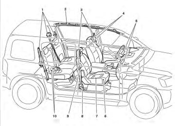
1. Window lock button 2. 3. 4. 5. 6.
Power door lock switch Front passenger’s side window switch Right rear passenger’s window switch Left rear passenger’s window switch Driver’s side automatic switch
Driver’s side power window switch The driver’s side control panel is equipped with switches to open or close the front and rear passenger windows. To open a window, push the switch and hold it down. To close a window, pull the switch and hold it up. To stop the opening or closing function at any time, simply release the switch.
Instruments and controls 2-47
WIC0343
WIC0874
LIC0410
Front passenger’s power window switch The passenger’s window switch operates only the corresponding passenger’s window. To open the window, push the switch and hold it down 䊊1 . To close the window, pull the switch up 䊊2 .
Rear power window switch The rear power window switches open or close only the corresponding windows. To open the window, push the switch and hold it down 䊊1 . To close the window, pull the switch up 䊊2 . Locking passengers’ windows When the window lock button is depressed, only the driver’s side window can be opened or closed. Push it again to cancel the window lock function.
Automatic operation To fully open a window equipped with automatic operation, press the window switch down to the second detent and release it; it need not be held. The window automatically opens all the way. To stop the window, lift the switch up while the window is opening.
2-48 Instruments and controls
INTERIOR LIGHTS
Type A
Type B
LIC0792
WIC0879
The interior lights have a three-position switch and operate regardless of ignition switch posi- tion. When the switch is in the ON position 䊊1 , the interior lights illuminate, regardless of door posi- tion. The lights will go off after about 15 minutes unless the ignition switch is in the ON position.
When the switch is in the ON, DOOR or normal position 䊊2 , the interior lights will stay on for about 30 seconds when:
● The doors are unlocked by the keyfob, a key, or the power door lock switch while all doors are closed and the ignition switch is in the OFF position.
● The driver’s door is opened and then closed while the key is removed from the ignition switch.
● The key is removed from the ignition switch
while all doors are closed.
The lights will turn off while the 30 second timer is activated when: ● The driver’s door is locked by the keyfob, a
key, or the power door lock switch.
● The ignition switch is placed in the ON po-
sition.
The lights will turn off automatically after 15 min- utes while doors are open to prevent the battery from becoming discharged. When the switch is in the OFF position 䊊3 , the interior lights do not illuminate, regardless of door position.
CAUTION
Do not use for extended periods of time with the engine stopped. This could result in a discharged battery.
Instruments and controls 2-49
MAP LIGHTS
CARGO LIGHT
LIC0790
To turn the map lights on, press the switches. To turn them off, press the switches again.CAUTION
Do not use for extended periods of time with the engine stopped. This could result in a discharged battery.
LIC0590
The cargo light on the overhead trim has a three- position switch. To operate, push the switch to the desired position. ON: The light is illuminated. Normal (center) position: The light illuminates when the lift gate is opened. The light turns off when the lift gate is closed. OFF: The light does not illuminate regardless of door position or lock status.2-50 Instruments and controls
3 Pre-driving checks and adjustments
Keys . . . . . . . . . . . . . . . . . . . . . . . . . . . . . . . . . . . . . . . . . . . . . 3-2
NISSAN Vehicle Immobilizer System keys . . . . . . . . . 3-2
Doors . . . . . . . . . . . . . . . . . . . . . . . . . . . . . . . . . . . . . . . . . . . . 3-3
Locking with key. . . . . . . . . . . . . . . . . . . . . . . . . . . . . . . . 3-3
Locking with inside lock knob . . . . . . . . . . . . . . . . . . . . 3-3
Locking with power door lock switch . . . . . . . . . . . . . 3-4
Automatic door locks . . . . . . . . . . . . . . . . . . . . . . . . . . . 3-4
Child safety rear door lock. . . . . . . . . . . . . . . . . . . . . . . 3-5
Remote keyless entry system . . . . . . . . . . . . . . . . . . . . . . . 3-5
How to use remote keyless entry system . . . . . . . . . . 3-6
Hood . . . . . . . . . . . . . . . . . . . . . . . . . . . . . . . . . . . . . . . . . . . . 3-9
Lift gate . . . . . . . . . . . . . . . . . . . . . . . . . . . . . . . . . . . . . . . . . . 3-9Fuel-filler door . . . . . . . . . . . . . . . . . . . . . . . . . . . . . . . . . . . 3-10
Opening the fuel-filler lid . . . . . . . . . . . . . . . . . . . . . . . 3-10
Fuel-filler cap . . . . . . . . . . . . . . . . . . . . . . . . . . . . . . . . . 3-10
Steering wheel . . . . . . . . . . . . . . . . . . . . . . . . . . . . . . . . . . . 3-12
Tilt operation . . . . . . . . . . . . . . . . . . . . . . . . . . . . . . . . . . 3-12
Sun visors . . . . . . . . . . . . . . . . . . . . . . . . . . . . . . . . . . . . . . . 3-12
Vanity mirrors (if so equipped). . . . . . . . . . . . . . . . . . . 3-13
Mirrors . . . . . . . . . . . . . . . . . . . . . . . . . . . . . . . . . . . . . . . . . . 3-13
Rearview mirror (if so equipped). . . . . . . . . . . . . . . . . 3-13
Automatic anti-glare rearview mirror (if so equipped) . . . . . . . . . . . . . . . . . . . . . . . . . . . . . . . 3-14
Outside mirrors . . . . . . . . . . . . . . . . . . . . . . . . . . . . . . . 3-14KEYS
1.
WPD0128
Two master keys (black) with transpon- der chip and chrome NISSAN brand symbol on one side Valet key (black) with transponder chip Key number plate Transponder chip2. 3. 4. A key number plate is supplied with your keys. Record the key number and keep it in a safe place (such as your wallet), not in the vehicle. If you lose your keys, see a NISSAN dealer for duplicates by using the key number. NISSAN does not record key numbers so it is very important to keep track of your key number plate.
3-2 Pre-driving checks and adjustments
After the registration process, these components will only recognize keys coded into the NISSAN Vehicle Immobilizer System during registration. Any key that is not given to your dealer at the time of registration will no longer be able to start your vehicle. Do not allow the immobilizer system key, which contains an electrical transponder, to come into contact with salt water. This could affect system function.
A key number is only necessary when you have lost all keys and do not have one to duplicate from. If you still have a key, your NISSAN dealer can duplicate it. NISSAN VEHICLE IMMOBILIZER SYSTEM KEYS You can only drive your vehicle using the master or valet keys which are registered to the NISSAN Vehicle Immobilizer System components in your vehicle. These keys have a transponder chip in the key head. The master key can be used for all the locks. To protect belongings when you leave a key with someone, give them the valet key only. Never leave these keys in the vehicle. Additional or replacement keys: If you still have a key, the key number is not necessary when you need extra NISSAN Vehicle Immobilizer System keys. Your dealer can dupli- cate your existing key. As many as five NISSAN Vehicle Immobilizer System keys can be used with one vehicle. You should bring all NISSAN Vehicle Immobilizer System keys that you have to your NISSAN dealer for registration. This is be- cause the registration process will erase the memory of all key codes previously registered into the NISSAN Vehicle Immobilizer System.
DOORS
When the doors are locked using one of the following methods, the doors can not be opened using the inside or outside door handles. The doors must be unlocked to open the doors.
WARNING
● Always have the doors locked while driving. Along with the use of seat belts, this provides greater safety in the event of an accident by helping to prevent persons from being thrown from the vehicle. This also helps keep children and others from unintentionally open- ing the doors, and will help keep out intruders.
● Before opening any door, always look
for and avoid oncoming traffic.
● Do not leave children unattended inside the vehicle. They could unknowingly ac- tivate switches or controls. Unattended children could become involved in seri- ous accidents.
Driver’s side
Inside lock
LPD0240
LPD0320
LOCKING WITH KEY The power door lock system allows you to lock or unlock all doors at the same time. Turning the key toward the front 䊊1 of the vehicle locks all doors. Turning the key one time toward the rear 䊊2 of the vehicle unlocks that door. From that position, returning the key to neutral 䊊3 (where the key can only be removed and inserted) and turning it toward the rear again within 5 seconds unlocks all doors 䊊4 .
LOCKING WITH INSIDE LOCK KNOB To lock the door without the key, move the inside lock knob to the lock position 䊊1 , then close the door. To unlock the door without the key, move the inside lock knob to the unlock position 䊊2 .
Pre-driving checks and adjustments 3-3
4. When activated, the hazard indicator will flash twice. When deactivated, the hazard indicator will flash once.
5. The ignition switch must be placed in the OFF and ON position again between each setting change.
When the automatic door unlock system is deac- tivated, the doors do not unlock when the key is removed from the ignition switch. To unlock the door manually, use the inside lock knob or the power door lock switch (driver’s or front passen- ger’s side).
When the power door lock switch (driver or pas- senger side) is moved to the lock position with the key in the ignition and any door open, all doors will lock and then unlock automatically. Lockout protection When the power door lock switch (driver’s or front passenger’s side) is moved to the lock position with the key in the ignition switch and any door open, all doors will lock and then unlock automatically. This helps to prevent the keys from being accidently locked inside the vehicle. AUTOMATIC DOOR LOCKS ● All doors lock automatically when the vehicle
speed reaches 15 MPH (24 km/h).
● All doors unlock automatically when the key
is removed from the ignition switch.
The automatic unlock function can be de- activated or activated. To deactivate or acti- vate the automatic door unlock system, perform the following procedure: 1. Close all doors. 2. Place the ignition switch in the ON position. 3. Within 20 seconds of performing Step 2, push and hold the power door lock switch to position (UNLOCK) for more than the 5 seconds.
WPD0381
Driver’s side
LOCKING WITH POWER DOOR LOCK SWITCH To lock all the doors without a key, push the door lock switch (driver or front passenger side), to the lock position 䊊1 , then close the door. When locking the door this way, be certain not to leave the key inside the vehicle. To unlock all the doors without a key, push the door lock switch (driver or front passenger side) to the unlock position 䊊2 .
3-4 Pre-driving checks and adjustments
REMOTE KEYLESS ENTRY SYSTEM
WARNING
The remote keyless entry keyfob trans- mits radio waves when the buttons are pushed. The FAA advises radio waves may affect aircraft navigation and communica- tion systems. Do not operate the remote keyless entry keyfob while on an airplane. Make sure the buttons are not operated unintentionally when the unit is stored for a flight.
It is possible to lock/unlock all doors, turn the interior light on, and activate the panic alarm by using the keyfob from outside the vehicle. Be sure to remove the key from the vehicle before locking the doors. The keyfob can operate at a distance of approxi- mately 33 ft (10 m) from the vehicle. The effective distance depends upon the conditions around the vehicle. As many as 5 keyfobs can be used with one vehicle. For information concerning the purchase and use of additional keyfobs, contact a NISSAN dealer.
The keyfob will not function when: ● the battery is discharged ● the distance between the vehicle and the
keyfob is over 33 ft (10 m)
The panic alarm will not activate when the key is in the ignition switch.
CAUTION
Listed below are conditions or occur- rences which will damage the keyfob: ● Do not allow the keyfob, which contains electrical components, to come into contact with water or salt water. This could affect the system function.
● Do not drop the keyfob. ● Do not strike the keyfob sharply against
another object.
● Do not change or modify the keyfob. ● Wetting may damage the keyfob. If the keyfob gets wet, immediately wipe until it is completely dry.
● Do not place the keyfob for an extended period in an area where temperatures exceed 140°F (60°C).
Pre-driving checks and adjustments 3-5
WPD0321
CHILD SAFETY REAR DOOR LOCK Child safety locks help prevent the rear doors from being opened accidentally, especially when small children are in the vehicle. The child safety lock levers are located on the edge of the rear doors. When the lever is in the LOCK position, the door can be opened only from the outside.● When the
button is pressed with all doors locked, the hazard warning lights flash twice and the horn beeps once as a reminder the doors are already locked.
that
● If a door
is open and you press button, the doors will lock the but the horn will not beep and the hazard lights will not flash.
The horn may or may not beep. Refer to “Silenc- ing the horn beep feature” in this section for details.
● Do not attach the keyfob with a key
holder that contains a magnet.
● Do not place the keyfob near equip- ment that produces a magnetic field, such as a TV, audio equipment and per- sonal computers.
If a keyfob is lost or stolen, NISSAN rec- ommends erasing the ID code of that key- fob. This will prevent the keyfob from un- authorized use to unlock the vehicle. For information regarding the erasing proce- dure, please contact a NISSAN dealer.
3-6 Pre-driving checks and adjustments
LPD0209
HOW TO USE REMOTE KEYLESS ENTRY SYSTEM Locking doors 1. Close all windows.
2. Remove the key from the ignition switch.
3. Close the hood and all doors.
4. Press the
button on the keyfob. All the doors lock. The hazard warning lights flash twice and the horn beeps once to indicate all doors are locked.
button on the keyfob again
Press the within 5 seconds. ● All doors unlock. ● The hazard warning lights flash once if all
doors are completely closed.
The interior lights can be turned off without wait- ing 30 seconds by inserting the key into the ignition switch and placing the ignition switch in the ON or START position, locking the doors with the keyfob or pushing the interior light switch to the OFF position. Auto relock button on the keyfob is pressed, When the all doors will lock automatically within 1 minute unless one of the following operations is per- formed: ● Any door is opened. ● A key is inserted into the ignition switch and
the switch is cycled from OFF to ON.
LPD0210
button on the keyfob once.
Unlocking doors Press the ● Only the driver’s door unlocks. ● The hazard warning lights flash once if all doors are completely closed with the ignition switch in any position except the ON posi- tion.
● The interior lights illuminate for 30 seconds when the interior light switch is in the normal operation position.
LPD0211
Using the panic alarm If you are near your vehicle and feel threatened, you may activate the panic alarm to call attention button on the by pressing and holding the keyfob for longer than 0.5 seconds. The panic alarm and headlights will stay on for 25
seconds. The panic alarm stops when: ● it has run for 25 seconds, or ● any button is pressed on the keyfob.Pre-driving checks and adjustments 3-7
button on the keyfob once to
Using the interior lights Press the turn on the interior lights. For additional information, refer to “Interior lights” in the “Instruments and controls” section in this manual.
The hazard warning lights will flash once and the horn will sound once to confirm that the horn beep feature has been reactivated. Deactivating the horn beep feature does not si- lence the horn if the alarm is triggered.
LPD0262
Silencing the horn beep feature If desired, the horn beep feature can be deacti- vated using the keyfob.
To deactivate: Press and hold the and
buttons for at least 2 seconds.
The hazard warning lights will flash three times to confirm that the horn beep feature has been deactivated.
To activate: Press and hold the and once more.
buttons for at least 2 seconds
3-8 Pre-driving checks and adjustments
HOOD
LIFT GATE
WARNING
WARNING
● Make sure the hood is completely closed and latched before driving. Fail- ure to do so could cause the hood to fly open and result in an accident.
● If you see steam or smoke coming from the engine compartment, to avoid injury do not open the hood.
● Always be sure the lift gate has been closed securely to prevent it from open- ing while driving.
● Do not drive with the lift gate open. This could allow dangerous exhaust gases to be drawn into the vehicle. See “Ex- haust gas” in the “Starting and driving” section of this manual.
● Make sure that all passengers have their hands, etc., inside the vehicle be- fore closing the lift gate.
LPD0302
䊊1 Pull the hood lock release handle located below the driver’s side instrument panel. The hood will spring up slightly.䊊2 Push the lever at the front of the hood to the side as illustrated with your fingertips and raise the hood. Insert the support rod into the slot on the underside of the hood.
䊊3
When closing the hood, return the hood rod to its original position. Lower the hood approximately 12 inch (30 cm) above the latch and release it. This allows proper engagement of the hood latch.
Pre-driving checks and adjustments 3-9
FUEL-FILLER DOOR
● Do not attempt to top off the fuel tank after the fuel pump nozzle shuts off automatically. Continued refueling may cause fuel overflow, resulting in fuel spray and possibly a fire.
● Use only an original equipment type fuel-filler cap as a replacement. It has a built-in safety valve needed for proper operation of the fuel system and emis- sion control system. An incorrect cap can result in a serious malfunction and possible injury. It could also cause Malfunction Indicator Light the (MIL) to come on.
● Never pour fuel into the throttle body to
attempt to start your vehicle.
● Do not fill a portable fuel container in the vehicle or trailer. Static electricity can cause an explosion of flammable liquid, vapor or gas in any vehicle or trailer. To reduce the risk of serious injury or death when filling portable fuel containers: – Always place the container on the
ground when filling.
– Do not use electronic devices when
filling.
LPD0322
The power door lock system allows you to lock or unlock all doors including the lift gate simultane- ously. To open the lift gate, pull up on the handle. To close, lower and push the lift gate down se- curely.LPD0460
OPENING THE FUEL-FILLER LID Pull the lid to open. FUEL-FILLER CAP
WARNING
● Gasoline is extremely flammable and highly explosive under certain condi- tions. You could be burned or seriously injured if it is misused or mishandled. Always stop the engine and do not smoke or allow open flames or sparks near the vehicle when refueling.
3-10 Pre-driving checks and adjustments
– Keep the pump nozzle in contact with the container while you are fill- ing it.
– Use only approved portable fuel con-
tainers for flammable liquid.
CAUTION
● The LOOSE FUEL CAP warning mes- sage will be displayed if the fuel-filler cap is not properly tightened. Failure to tighten the fuel-filler cap properly after the LOOSE FUEL CAP warning message Mal- is displayed may cause the function Indicator Light to illuminate.
(MIL)
● Failure to tighten the fuel-filler cap Mal- properly may cause the function Indicator Light (MIL) to illumi- light illuminates be- nate. If the cause the fuel-filler cap is loose or missing, tighten or install the cap and to continue vehicle. light should turn off after a The
drive
the
If the
few driving trips. light does not turn off after a few driving trips, have the vehicle inspected by a NISSAN dealer. ● For additional
information, see the “Malfunction Indicator Light (MIL)” in the “Instruments and Controls” section in this manual.
● If fuel is spilled on the vehicle body, flush it away with water to avoid paint damage.
LPD0323
To remove the fuel-filler cap: 1. Turn the fuel-filler cap counterclockwise to
remove.
2. Put the fuel-filler cap on the cap holder 䊊1
while refueling.
To install the fuel-filler cap: 1.
Insert the fuel-filler cap straight into the fuel- filler tube.
2. Turn the fuel-filler cap clockwise until
it clicks. The fuel-filler cap is a ratcheting type.
Pre-driving checks and adjustments 3-11
STEERING WHEEL
SUN VISORS
LRS2004
LPD0304
Loose Fuel Cap warning message The LOOSE FUEL CAP warning message dis- plays in the odometer when the fuel-filler cap is not tightened correctly after the vehicle has been refueled. To turn off the warning message, do the following: 1. Remove and install the fuel-filler cap as pre-
viously described as soon as possible. 2. Tighten the fuel-filler cap until it clicks. 3. Press the loose fuel cap warning reset but- ton 䊊A in the meter for about 1 second to turn off the LOOSE FUEL CAP warning message after tightening the fuel-filler cap.
3-12 Pre-driving checks and adjustments
TILT OPERATION
WARNING
Do not adjust the steering wheel while driving. You could lose control of your vehicle and cause an accident.
Pull the lock lever forward and hold it to adjust the steering wheel up or down to the desired posi- tion. Release the lock lever to lock the steering wheel in place.
WPD0315
䊊1 To block glare from the front, swing down themain sun visor.
䊊2 To block glare from the side, remove the main sun visor from the center mount and swing the visor to the side.
MIRRORS
䊊3 Slide the extension sun visor (if so equipped)
in or out as needed.
CAUTION
● Do not store the sun visor before return- ing the extension to its original position.
● Do not pull the extension sun visor
forcedly downward.
WPD0307
VANITY MIRRORS (if so equipped) To access the vanity mirror, pull the sun visor down and flip open the mirror cover. Some vanity mirrors are illuminated and turn on when the mirror cover is open.
WPD0126
REARVIEW MIRROR (if so equipped) The night position 䊊1 reduces glare from the headlights of vehicles behind you at night. Use the day position 䊊2 when driving in daylight hours.WARNING
Use the night position only when neces- sary, because it reduces rear view clarity.
Pre-driving checks and adjustments 3-13
NOTE:
OUTSIDE MIRRORS
Do not hang any objects over the sensors 䊊1 or apply glass cleaner to the sensors. Doing so will reduce the sensitivity of the sensors, resulting in improper operation.
The indicator light will illuminate when the auto- matic anti-glare feature is operating.
With the ignition switch in the ON position, press the ● To turn off
button as described:
the anti-glare feature, press button. The indicator light will turn
LPD0446
the off.
WARNING
● Objects viewed in the outside mirror on the passenger side are closer than they appear. Be careful when moving to the right. Using only this mirror could cause an accident. Use the inside mirror or glance over your shoulder to properly judge distances to other objects.
AUTOMATIC ANTI-GLARE REARVIEW MIRROR (if so equipped) The inside mirror is designed so that it automati- cally dims according to the intensity of the head- lights of the vehicle following you. The automatic anti-glare feature is activated when the ignition switch is in the ON position.
● To turn on the anti-glare feature, press button again. The indicator light
the will turn on.
For more information about the 䊊2 compass and compass features (if so equipped), to “Compass display” in the “Instruments and con- trols” section of this manual.
refer
3-14 Pre-driving checks and adjustments
WPD0170
LPD0237
Manual control type (if so equipped) The outside mirror can be moved in any direction for a better rear view.
Electric control type (if so equipped) The outside mirror remote control will operate only when the ignition switch is placed in the ACC or ON position. Move the small switch 䊊1 to select the right or left mirror. Adjust each mirror to the desired position using the large switch 䊊2 .
Heated mirrors (Canada only) (if so equipped) Some outside mirrors can be heated to defrost, defog, or de-ice for improved visibility. For addi- tional information, see “Rear window and outside mirror defroster switch” in the “Instruments and controls” section of this manual.
Pre-driving checks and adjustments 3-15
Foldable outside mirrors Pull the outside mirror toward the door to fold it.
LPD0259
3-16 Pre-driving checks and adjustments
4 Heater, air conditioner, audio and phone systems
Vents . . . . . . . . . . . . . . . . . . . . . . . . . . . . . . . . . . . . . . . . . . . . 4-2
Heater and air conditioner (manual) (Type A). . . . . . . . . . 4-2
Controls. . . . . . . . . . . . . . . . . . . . . . . . . . . . . . . . . . . . . . . 4-3
Heater operation . . . . . . . . . . . . . . . . . . . . . . . . . . . . . . . 4-4
Air conditioner operation . . . . . . . . . . . . . . . . . . . . . . . . 4-5
Air flow charts. . . . . . . . . . . . . . . . . . . . . . . . . . . . . . . . . . 4-6
Heater and air conditioner (manual) (Type B). . . . . . . . . 4-10
Controls. . . . . . . . . . . . . . . . . . . . . . . . . . . . . . . . . . . . . . 4-10
Heater operation . . . . . . . . . . . . . . . . . . . . . . . . . . . . . . 4-11
Air conditioner operation . . . . . . . . . . . . . . . . . . . . . . . 4-12
Air flow charts. . . . . . . . . . . . . . . . . . . . . . . . . . . . . . . . . 4-13
Servicing air conditioner. . . . . . . . . . . . . . . . . . . . . . . . . . . 4-17
Audio system . . . . . . . . . . . . . . . . . . . . . . . . . . . . . . . . . . . . 4-17
Radio . . . . . . . . . . . . . . . . . . . . . . . . . . . . . . . . . . . . . . . . 4-17
FM radio reception . . . . . . . . . . . . . . . . . . . . . . . . . . . . 4-17
AM radio reception . . . . . . . . . . . . . . . . . . . . . . . . . . . . 4-18
Satellite radio reception (if so equipped) . . . . . . . . . 4-18
Audio operation precautions . . . . . . . . . . . . . . . . . . . . 4-18FM/AM radio with compact disc (CD) player (Type A and B) (if so equipped) . . . . . . . . . . . . . . . . . 4-25
FM/AM/SAT radio with compact disc (CD) changer (if so equipped) . . . . . . . . . . . . . . . . . . . . . . . 4-29
CD care and cleaning . . . . . . . . . . . . . . . . . . . . . . . . . . 4-35
Steering wheel switch for audio control (if so equipped) . . . . . . . . . . . . . . . . . . . . . . . . . . . . . . . 4-36
Antenna . . . . . . . . . . . . . . . . . . . . . . . . . . . . . . . . . . . . . . 4-37
Car phone or CB radio . . . . . . . . . . . . . . . . . . . . . . . . . . . . 4-37
Bluetooth姞 Hands-Free Phone System (if so equipped) . . . . . . . . . . . . . . . . . . . . . . . . . . . . . . . . . . 4-38
Regulatory Information . . . . . . . . . . . . . . . . . . . . . . . . . 4-39
Using the system . . . . . . . . . . . . . . . . . . . . . . . . . . . . . . 4-40
Control buttons . . . . . . . . . . . . . . . . . . . . . . . . . . . . . . . 4-42
Getting started . . . . . . . . . . . . . . . . . . . . . . . . . . . . . . . . 4-42
List of voice commands . . . . . . . . . . . . . . . . . . . . . . . . 4-44
Speaker Adaptation (SA) mode . . . . . . . . . . . . . . . . . 4-49
Manual control . . . . . . . . . . . . . . . . . . . . . . . . . . . . . . . . 4-50
Troubleshooting guide . . . . . . . . . . . . . . . . . . . . . . . . . 4-51HEATER AND AIR CONDITIONER (manual) (Type A)
WARNING
● The air conditioner cooling function op- erates only when the engine is running. ● Do not leave children or adults who would normally require the assistance of others alone in your vehicle. Pets should also not be left alone. They could accidentally injure themselves or others through inadvertent operation of the vehicle. Also, on hot, sunny days, temperatures in a closed vehicle could quickly become high enough to cause severe or possibly fatal injuries to people or animals.
● Do not use the recirculation mode for long periods as it may cause the interior air to become stale and the windows to fog up.
WHA1165
VENTS
Adjust air flow direction for the driver’s side vents 䊊1 , center vents 䊊2 , and passenger’s side vents 䊊3 by moving the vent slide and/or vent assem- blies.
4-2 Heater, air conditioner, audio and phone systems
— Air flows from center and side
vents.
— Air flows from center and side
vents and foot outlets.
— Air flows mainly from foot outlets. — Air flows from defroster outlets and
foot outlets.
— Air flows mainly from defroster
outlets.
Temperature control dial The temperature control dial allows you to adjust the temperature of the outlet air. To lower the temperature, turn the dial to the left. To increase the temperature, turn the dial to the right.
Air recirculation button
ON position (Indicator light on): Interior air is recirculated inside the vehicle.
button to the on position when:
Press the ● driving on a dusty road. ● to prevent traffic fumes from entering pas-
senger compartment.
● for maximum cooling when using the air con-
ditioner.
Type A
WHA1406
CONTROLS Fan control dial The fan control dial turns the fan on and off, and controls fan speed. Air flow control buttons The air flow control buttons allow you to select the air flow outlets. MAX A/C
— Air flows from center and side
vents with maximum cooling (air conditioning).
Heater, air conditioner, audio and phone systems 4-3
1. 2. 3.
Fan speed control dial Front window defroster button Rear window and outside mirror (if so equipped) defroster button Air recirculation button Temperature control dial
4. 5. 6. MAX A/C button 7. 8.
Air flow control buttons Air conditioner button
OFF position (Indicator light off): Outside air is drawn into the passenger compart- ment and distributed through the selected outlet. Use the off position for normal heater or air con- ditioner operation.
Air conditioner button
Start the engine, turn the fan control dial to the desired position and push the button to turn on the air conditioner. The indicator light comes on when the air conditioner is operating. To turn off the air conditioner, push the button again. The air conditioner cooling function oper- ates only when the engine is running. Rear window and outside mirror (if so equipped) defroster switch For more information about the rear window and outside mirror (if so equipped) defroster switch, see “Rear window and outside mirror defroster switch” in the “Instruments and controls” section of this manual.
HEATER OPERATION Heating This mode is used to direct heated air to the foot outlets. Some air also flows from the defrost outlets.
4. Turn the temperature control dial to the de-
sired position.
Defrosting or defogging This mode directs the air to the defrost outlets to defrost/defog the windows.
1. Press the
button to the OFF position for normal heating. The indicator light on the
button will go off.
2. Press the
air flow control button.
3. Turn the fan control dial to the desired posi-
tion.
4. Turn the temperature control dial to the de- sired position between the middle and the hot position.
Ventilation This mode directs outside air to the side and center ventilators.
1. Press the
The indicator light on the go off.
button to the OFF position. button will
1. Press the defrost/defog button 2. Turn the fan control dial to the desired posi-
tion.
3. Turn the temperature control dial to the de- sired position between the middle and the hot position.
● To quickly remove ice or fog from the win- dows, turn the fan control dial to the highest setting and the temperature control to the full HOT position.
● When the
position is selected, the air conditioner automatically turns on (the indi- button will come on) cator light on the if the outside temperature is more than 36°F (2°C). This dehumidifies the air which helps mode au- defog the windshield. The tomatically turns off, allowing outside air to be drawn into the passenger compartment to further improve the defogging perfor- mance.
4-4 Heater, air conditioner, audio and phone systems
2. Press the
air flow control button.
3. Turn the fan control dial to the desired posi-
tion.
Bi-level heating The bi-level mode directs warmed air to the side and center vents and to the front and rear floor outlets.
1. Press the
The indicator light on the go off.
button to the OFF position. button will
2. Press the
air flow control button.
3. Turn the fan control dial to the desired posi-
tion.
4. Turn the temperature control dial to the de-
sired position.
Heating and defogging This mode heats the interior and defogs the wind- shield.
1. Press the
air flow control button.
2. Turn the fan control dial to the desired posi-
tion.
3. Turn the temperature control dial to the de- sired position between the middle and the hot position.
● When the
position is selected, the air conditioner automatically turns on (however, button will the indicator light on the not come on) if the outside temperature is air flow more than 36°F (2°C). If the control button is selected for more than one minute, the air conditioning system will con- tinue to operate until the fan control dial is turned to OFF, the vehicle is shut off, or the A/C button is used to turn off the compres- sor even if the air flow control dial is turned to position. a position other than the This dehumidifies the air which helps defog mode automati- the windshield. The cally turns off, allowing outside air to be drawn into the passenger compartment to further improve the defogging performance.
Operating tips Clear snow and ice from the wiper blades and air inlet in front of the windshield. This improves heater operation. AIR CONDITIONER OPERATION Start the engine, turn the fan control dial to the desired position, and push in the button to activate the air conditioner. When the air condi- tioner is on, cooling and dehumidifying functions are added to the heater operation.
The air conditioner cooling function oper- ates only when the engine is running. Cooling This mode is used to cool and dehumidify the air.
1. Press the
button to the OFF position.
2. Press the 3. Turn the fan control dial to the desired posi-
air flow control button.
tion.
4. Press the
button. The indicator light
on the
button will come on.
5. Turn the temperature control dial to the de-
sired position.
● For quick cooling when the outside tem- button to light on button will come on. Be sure to to the OFF position for nor-
perature is high, push the the ON position. The indicator the return the mal cooling. The indicator light on the button will go off. You may also select MAX A/C for quick cooling.
Heater, air conditioner, audio and phone systems 4-5
AIR FLOW CHARTS The following charts show the button and dial positions for MAXIMUM AND QUICK heating, cooling or defrosting. For additional information on heating and cooling, see “Heater and air con- ditioner (manual)” in this section. The air recir- ) button should always be in culation ( the OFF position for heating and defrost- ing.
Dehumidified defogging This mode is used to defog the windows and dehumidify the air.
Operating tips ● Keep the windows closed while the air con-
ditioner is in operation.
1. Press the
air flow control button.
2. Turn the fan control dial to the desired posi-
tion.
3. Press the comes on.
button. The indicator light
or
positions are se- When the lected, the air conditioner automatically turns on (however, the indicator light will not illuminate) if the outside temperature is more than 36°F (2°C). If one of these air flow control buttons is selected for more than one minute, the air conditioning system will continue to operate until the fan con- trol dial is turned to OFF, the air conditioner is turned OFF, or the vehicle is shut off, even if a position other than these positions is selected. This dehumidifies the air which helps defog the mode automatically turns windshield. The off, allowing outside air to be drawn into the passenger compartment to further improve the defogging performance.
4. Turn the temperature control dial to the de-
sired position.
● After parking in the sun, drive for 2 or 3
minutes with the windows open to vent hot air from the passenger compartment. Then, close the windows. This allows the air con- ditioner to cool the interior more quickly.● The air conditioning system should be operated for approximately 10 minutes at least once a month. This helps pre- vent damage to the system due to lack of lubrication.
● A visible mist may be seen coming from the ventilators in hot, humid conditions as the air is cooled rapidly. This does not indicate a malfunction.
● If
the engine coolant
temperature gauge indicates engine coolant tem- perature over the normal range, turn the air conditioner off. See “If your vehicle overheats” in the “In case of emergency” section of this manual.
4-6 Heater, air conditioner, audio and phone systems
WHA0916
WHA0917
Heater, air conditioner, audio and phone systems 4-74-8 Heater, air conditioner, audio and phone systems
WHA0918
WHA0919
WHA1362
Heater, air conditioner, audio and phone systems 4-9
HEATER AND AIR CONDITIONER (manual) (Type B)
WARNING
● The air conditioner cooling function op- erates only when the engine is running. ● Do not leave children or adults who would normally require the assistance of others alone in your vehicle. Pets should also not be left alone. They could accidentally injure themselves or others through inadvertent operation of the vehicle. Also, on hot, sunny days, temperatures in a closed vehicle could quickly become high enough to cause severe or possibly fatal injuries to people or animals.
● Do not use the recirculation mode for long periods as it may cause the interior air to become stale and the windows to fog up.
Type B
LHA0489
Fan control dial Temperature control dial Air flow control dial Air conditioner button Rear window defroster button Air recirculation button
1. 2. 3. 4. 5. 6. CONTROLS Fan control dial The fan control dial turns the fan on and off, and controls fan speed.
Air flow control dial The air flow control dial allows you to select the air flow outlets. MAX A/C
— Air flows from center and side
vents with maximum cooling.
— Air flows from center and side
vents.
— Air flows from center and side
vents and foot outlets.
— Air flows mainly from foot outlets. — Air flows from defroster outlets
and foot outlets.
4-10 Heater, air conditioner, audio and phone systems
— Air flows mainly from defroster
outlets.
Use the off position for normal heater or air con- ditioner operation.
● When the
or
position is mode selected, the air recirculation cannot be turned on. This prevents the win- dows from fogging.
Temperature control dial The temperature control dial allows you to adjust the temperature of the outlet air. To lower the temperature, turn the dial to the left. To increase the temperature, turn the dial to the right.
Air recirculation button
ON position (Indicator light on): Interior air is recirculated inside the vehicle.
button to the on position when:
Press the ● driving on a dusty road. ● to prevent traffic fumes from entering pas-
senger compartment.
● for maximum cooling when using the air con-
ditioner.
OFF position (Indicator light off): Outside air is drawn into the passenger compart- ment and distributed through the selected outlet.
Air conditioner button
Start the engine, turn the fan control dial to the desired (1 to 4) position and push the button to turn on the air conditioner. The indicator button will come on. Push light on the button again to turn off the air condi- the button will tioner. The indicator light on the go off. The air conditioner cooling function oper- ates only when the engine is running. Rear window defroster switch For more information about the rear window de- froster switch, see “Rear window and outside mirror defroster switch” in the “Instruments and controls” section of this manual. HEATER OPERATION Heating This mode is used to direct heated air to the foot outlets. Some air also flows from the defrost outlets.
1. Push the
button to the OFF position for normal heating. The indicator light on the
button will go off.
2. Turn the air flow control dial to the
position.
3. Turn the fan control dial to the desired posi-
tion.
4. Turn the temperature control dial to the de- sired position between the middle and the hot position.
Ventilation This mode directs outside air to the side and center vent.
1. Push the
button to the OFF position. button will
The indicator light on the go off.
2. Turn the air flow control dial to the
position.
3. Turn the fan control dial to the desired posi-
tion.
4. Turn the temperature control dial to the de-
sired position.
Heater, air conditioner, audio and phone systems 4-11
Defrosting or defogging This mode directs the air to the defrost outlets to defrost/defog the windows.
1. Turn the air flow control dial to the
position.
2. Turn the fan control dial to the desired position. 3. Turn the temperature control dial to the de- sired position between the middle and the hot position.
● To quickly remove ice or fog from the win- dows, turn the fan control dial to 4 and the temperature control lever to the full HOT position.
● When the
position is selected, the air conditioner automatically turns on (however, the indicator light will not illuminate) if the outside temperature is more than 36°F (2°C). If the system is in defrost mode for more than one minute, the air conditioning system will continue to operate until the fan control dial is turned to OFF or the vehicle is shut off, even if the air flow control dial is turned to a position position. This dehumidi- other than the fies the air which helps defog the windshield. mode automatically turns off, al- The lowing outside air to be drawn into the pas- senger compartment to further improve the defogging performance.
Bi-level heating The bi-level mode directs warmed air to the side and center vents and to the front and rear floor outlets.
1. Push the
button to the OFF position. button will
The indicator light on the go off.
2. Turn the air flow control dial to the
position.
3. Turn the fan control dial to the desired posi-
tion.
4. Turn the temperature control dial to the de-
sired position.
Heating and defogging This mode heats the interior and defogs the wind- shield.
1. Turn the air flow control dial to the
position.
2. Turn the fan control dial to the desired posi-
tion.
3. Turn the temperature control dial to the de- sired position between the middle and the hot position.
● When the
position is selected, the air conditioner automatically turns on (however, button will the indicator light on the not come on) if the outside temperature is more than 36°F (2°C). If the air flow control position for more than dial is in the one minute, the air conditioning system will continue to operate until the fan control dial is turned to OFF or the vehicle is shut off, even if the air flow control dial is turned to a position. This position other than the dehumidifies the air which helps defog the mode automatically windshield. The turns off, allowing outside air to be drawn into the passenger compartment to further improve the defogging performance.
Operating tips Clear snow and ice from the wiper blades and air inlet in front of the windshield. This improves heater operation. AIR CONDITIONER OPERATION Start the engine, turn the fan control dial to the button to desired position, and push in the activate the air conditioner. When the air condi- tioner is on, cooling and dehumidifying functions are added to the heater operation.
4-12 Heater, air conditioner, audio and phone systems
The air conditioner cooling function oper- ates only when the engine is running. Cooling This mode is used to cool and dehumidify the air.
1. Push the
button to the off position.
2. Turn the air flow control dial to the
position.
3. Turn the fan control dial to the desired posi-
tion.
4. Push the comes on.
button. The indicator light
5. Turn the temperature control dial to the de-
sired position.
● For quick cooling when the outside tem- button to perature is high, push the the on position (indicator light on). Be sure button to the off position to return the for normal cooling.
Dehumidified defogging This mode is used to defog the windows and dehumidify the air.
1. Turn the air flow control dial to the
position.
2. Turn the fan control dial to the desired posi-
tion.
3. Push the comes on.
button. The indicator light
is in the
When the air flow control dial position, the air conditioner automati- or cally turns on (however, the indicator light will not illuminate) if the outside temperature is more than 36°F (2°C). If one of these positions is selected for more than one minute, the air conditioning system will continue to operate until the fan con- trol dial is turned to OFF or the vehicle is shut off, even if the air flow control dial is turned to a position other than these positions. This dehu- midifies the air which helps defog the windshield. mode automatically turns off, allowing The outside air to be drawn into the passenger com- partment to further improve the defogging perfor- mance.
4. Turn the temperature control dial to the de-
sired position. Operating tips ● Keep the windows closed while the air con-
ditioner is in operation.
● After parking in the sun, drive for 2 or 3
minutes with the windows open to vent hot air from the passenger compartment. Then, close the windows. This allows the air con- ditioner to cool the interior more quickly.● The air conditioning system should be operated for approximately 10 minutes at least once a month. This helps pre- vent damage to the system due to lack of lubrication.
● A visible mist may be seen coming from the ventilators in hot, humid conditions as the air is cooled rapidly. This does not indicate a malfunction.
● If
the engine coolant
temperature gauge indicates engine coolant tem- perature over the normal range, turn the air conditioner off. See “If your vehicle overheats” in the “In case of emergency” section of this manual.
AIR FLOW CHARTS The following charts show the button and dial posi- tions for MAXIMUM AND QUICK heating, cooling or defrosting. For additional information on heat- ing and cooling, see “Heater and air conditioner (manual)” in this section. The air recirculation ) button should always be in the OFF position for heating and defrosting.
Heater, air conditioner, audio and phone systems 4-13
4-14 Heater, air conditioner, audio and phone systems
WHA0775
WHA0776
WHA0777
WHA0778
Heater, air conditioner, audio and phone systems 4-154-16 Heater, air conditioner, audio and phone systems
WHA1074
SERVICING AIR CONDITIONER
AUDIO SYSTEM
The air conditioner system in your NISSAN ve- hicle is charged with a refrigerant designed with the environment in mind. This refrigerant does not harm the earth’s ozone layer. Special charging equipment and lubricant is re- quired when servicing your NISSAN air condi- tioner. Using improper refrigerants or lubricants will cause severe damage to your air conditioner system. See “Air conditioner system refrigerant and oil recommendations” in the “Technical and consumer information” section of this manual. A NISSAN dealer is able to service your “environ- mentally friendly” air conditioning system.
WARNING
The air conditioner system contains re- frigerant under high pressure. To avoid personal injury, any air conditioner ser- vice should be done only by an experi- enced technician with proper equipment.
RADIO Place the ignition switch in the ACC or ON position and press the PWR (power)/VOL (vol- ume) knob to turn the radio on. If you listen to the radio with the engine not running, the ignition switch should be placed in the ACC position.
Radio reception is affected by station signal strength, distance from radio transmitter, build- ings, bridges, mountains and other external influ- ences. Intermittent changes in reception quality normally are caused by these external influences. Using a cellular phone in or near the ve- hicle may influence radio reception quality. Radio reception Your NISSAN radio system is equipped with state-of-the-art electronic circuits to enhance ra- dio reception. These circuits are designed to extend reception range, and to enhance the qual- ity of that reception.
However, there are some general characteristics of both FM and AM radio signals that can affect radio reception quality in a moving vehicle, even when the finest equipment is used. These char- acteristics are completely normal in a given re- ception area and do not indicate any malfunction in your NISSAN radio system.
Reception conditions will constantly change be- cause of vehicle movement. Buildings, terrain, signal distance and interference from other ve- hicles can work against ideal reception. De- scribed below are some of the factors that can affect your radio reception. Some cellular phones or other devices may cause interference or a buzzing noise to come from the audio system speakers. Storing the de- vice in a different location may reduce or elimi- nate the noise. FM RADIO RECEPTION Range: FM range is normally limited to 25 – 30 mi (40 – 48 km), with monaural (single channel) FM having slightly more range than stereo FM. Exter- nal influences may sometimes interfere with FM station reception even if the FM station is within 25 mi (40 km). The strength of the FM signal is directly related to the distance between the transmitter and receiver. FM signals follow a line- of-sight path, exhibiting many of the same char- acteristics as light. For example, they will reflect off objects. Fade and drift: As your vehicle moves away from a station transmitter, the signals will tend to fade and/or drift.
Heater, air conditioner, audio and phone systems 4-17
Static and flutter: During signal interference from buildings, large hills or due to antenna position (usually in conjunction with increased distance from the station transmitter), static or flutter can be heard. This can be reduced by adjusting the treble control to reduce treble response. Multipath reception: Because of the reflective characteristics of FM signals, direct and reflected signals reach the receiver at the same time. The signals may cancel each other, resulting in mo- mentary flutter or loss of sound. AM RADIO RECEPTION AM signals, because of their low frequency, can bend around objects and skip along the ground. In addition, the signals can be bounced off the ionosphere and bent back to earth. Because of these characteristics, AM signals are also sub- ject to interference as they travel from transmitter to receiver. Fading: Occurs while the vehicle is passing through freeway underpasses or in areas with many tall buildings. It can also occur for several seconds during ionospheric turbulence even in areas where no obstacles exist. Static: Caused by thunderstorms, electrical power lines, electric signs and even traffic lights.
SATELLITE RADIO RECEPTION (if so equipped) When the satellite radio is used for the first time or the battery has been replaced, the satellite radio may not work properly. This is not a mal- function. Wait more than 10 minutes with satellite radio ON and the vehicle outside of any metal or large building for satellite radio to receive all of the necessary data. No satellite radio reception is available and “NO SAT” is displayed when the SAT band option is selected unless optional satellite receiver and antenna are installed and an XM姞 satellite radio service subscription is active. Satellite radio can only be installed in vehicles that were factory pre-wired for satellite radio. Satellite radio is not available in Alaska, Hawaii and Guam. Satellite radio performance may be affected if cargo carried on the roof blocks the satellite radio signal. If possible, do not put cargo over the satellite antenna. A build up of ice on the satellite radio antenna can affect satellite radio performance. Remove the ice to restore satellite radio reception.
4-18 Heater, air conditioner, audio and phone systems
LHA0099
AUDIO OPERATION PRECAUTIONSCompact disc (CD) player
CAUTION
● Do not force a compact disc into the CD insert slot. This could damage the CD and/or CD changer/player.
● Trying to load a CD with the CD door closed could damage the CD and/or CD changer.
● Only one CD can be loaded into the CD
player at a time.
● Only use high quality 4.7 in (12 cm) round discs that have the “COMPACT disc DIGITAL AUDIO” logo on the disc or packaging.
● During cold weather or rainy days, the player may malfunction due to the hu- midity. If this occurs, remove the CD and dehumidify or ventilate the player completely.
● The player may skip while driving on
rough roads.
● The CD player sometimes cannot func- tion when the compartment tempera- ture low. Decrease/increase the temperature before use.
extremely high or
is
● Do not expose the CD to direct sun-
light.
● CDs that are in poor condition or are dirty, scratched or covered with finger- prints may not work properly.
● The following CDs may not work prop-
erly: ● Copy control compact discs (CCCD) ● Recordable compact discs (CD-R) ● Rewritable compact discs (CD-RW) ● Do not use the following CDs as they may cause the CD player to malfunc- tion: ● 3.1 in (8 cm) discs with an adapter ● CDs that are not round ● CDs with a paper label ● CDs that are warped, scratched, or
have abnormal edges
CHECK DISC:
● Confirm that the CD is inserted cor- rectly (the label side is facing up, etc.).
● Confirm that the CD is not bent or
warped and it is free of scratches.
PRESS EJECT:
This is an error due to excessive tem- perature inside the player. Remove the CD by pressing the EJECT button. After a short time, reinsert the CD. The CD can be played when the temperature of the player returns to normal.
UNPLAYABLE:
The file is unplayable in this audio sys- tem (only MP3 or WMA CD).
● This audio system can only play pre- recorded CDs. It has no capability to record or burn CDs.
● If the CD cannot be played, one of the following messages will be displayed.
Heater, air conditioner, audio and phone systems 4-19
● Sampling frequency — Sampling frequency is the rate at which the samples of a signal are converted from analog to digital (A/D conversion) per second.
● Multisession — Multisession is one of the methods for writing data to media. Writing data once to the media is called a single session, and writing more than once is called a multisession.
● ID3/WMA Tag — The ID3/WMA tag is the part of the encoded MP3 or WMA file that contains information about the digital music file such as song title, artist, encoding bit rate, track time duration, etc. ID3 tag infor- mation is displayed on the Artist/song title line on the display.
* Windows姞 and Windows Media姞 are regis- tered trademarks and trademarks in the United States of America and other countries of Micro- soft Corporation of the USA.
Compact disc with MP3 or WMA (if so equipped) Terms: ● MP3 — MP3 is short for Moving Pictures Experts Group Audio Layer 3. MP3 is the most well-known compressed digital audio file format. This format allows for near “CD quality” sound, but at a fraction of the size of normal audio files. MP3 conversion of an audio track from CD-ROM can reduce the file size by approximately a 10:1 ratio with virtually no perceptible loss in quality. MP3
compression removes the redundant and irrelevant parts of a sound signal that the human ear doesn’t hear.● WMA — Windows Media Audio (WMA)* is a compressed audio format created by Micro- soft as an alternative to MP3. The WMA codec offers greater file compression than the MP3 codec, enabling storage of more digital audio tracks in the same amount of space when compared to MP3s at the same level of quality.
● Bit rate — Bit rate denotes the number of bits per second used by a digital music file. The size and quality of a compressed digital audio file is determined by the bit rate used when encoding the file.
4-20 Heater, air conditioner, audio and phone systems
Playback order chart
WHA1078
Playback order: Music playback order of a CD with MP3 or WMA files is as illustrated. ● The names of folders not containing MP3 or
WMA files are not shown in the display.
● If there is a file in the top level of the disc,
“Root Folder” is displayed.
● The playback order is the order in which the files were written by the writing software. Therefore, the files might not play in the desired order.
Heater, air conditioner, audio and phone systems 4-21
Specification chart:
Supported media Supported file systems
Supported versions*1
MP3
WMA
Version Sampling frequency Bit rate Version Sampling frequency Bit rate
Tag information Folder levels Text character number limitation
Displayable character codes*2
CD, CD-R, CD-RW ISO9660 LEVEL1, ISO9660 LEVEL2, Apple ISO, Romeo, Joliet * ISO9660 Level 3 (packet writing) is not supported. MPEG1, MPEG2, MPEG2.5
8 kHz - 48 kHz 8 kbps - 320 kbps, VBR WMA7, WMA8, WMA9
32 kHz - 48 kHz 48 kbps - 192 kbps, VBR ID3 tag VER1.0, VER1.1, VER2.2, VER2.3 (MP3 only) Folder levels: 8, Max folders: 255 (including root folder), Files: 512 (Max. 255 files for one folder) 128 characters 01: ASCII, 02: ISO-8859-1, 03: UNICODE (UTF-16 BOM Big Endian), 04: UNICODE (UTF-16 Non-BOM Big Endian), 05: UNICODE (UTF-8), 06: UNICODE (Non-UTF-16 BOM Little Endian)*1 Files created with a combination of 48 kHz sampling frequency and 64 kbps bit rate cannot be played.
*2 Available codes depend on what kind of media, versions and information are going to be displayed.
4-22 Heater, air conditioner, audio and phone systems
Troubleshooting guide:
Symptom
Cannot play
Poor sound quality
It takes a relatively long time before the music starts playing.
Music cuts off or skips
Skipping with high bit rate files Moves immediately to the next song when playing Songs do not play back in the desired order
Cause and Countermeasure
Check if the disc was inserted correctly. Check if the disc is scratched or dirty. Check if there is condensation inside the player. If there is, wait until the condensation is gone (about 1 hour) before using the player. If there is a temperature increase error, the CD player will play correctly after it returns to the normal temperature. If there is a mixture of music CD files (CD-DA data) and MP3/WMA files on a CD, only the music CD files (CD-DA data) will be played. Files with extensions other than “.MP3”,“.WMA”, “.mp3” or “.wma” cannot be played. In addition, the character codes and number of characters for folder names and file names should be in compliance with the specifications. Check if the finalization process, such as session close and disc close, is done for the disc. Check if the disc is protected by copyright. Check if the disc is scratched or dirty. Bit rate may be too low. If there are many folders or file levels on the MP3/WMA disc, or if it is a multisession disc, some time may be required before the music starts playing.
The writing software and hardware combination might not match, or the writing speed, writing depth, writing width, etc., might not match the specifications. Try using the slowest writing speed. Skipping may occur with large quantities of data, such as for high bit rate data.
When a non-MP3/WMA file has been given an extension of “.MP3”, “.WMA”, .“mp3”or “.wma”, or when play is prohibited by copyright protection, there will be approximately 5 seconds of no sound and then the player will skip to the next song. The playback order is the order in which the files were written by the writing software. Therefore, the files might not play in the desired order.
Heater, air conditioner, audio and phone systems 4-23
11. Station select (1 - 6) buttons 12. SEEK buttons
WHA1075
PRESET A·B·C button CD eject button
1. 2. 3. MENU button 4. CD insert slot 5. CD button 4-24 Heater, air conditioner, audio and phone systems
Type A 6. 7. 8. 9. 10. RDM button
FM·AM button TUNE buttons RPT button PWR button/VOL control knob
11. Station select (1 - 6) buttons 12. SEEK button FM/AM RADIO WITH COMPACT DISC (CD) PLAYER (Type A and B) (if so equipped) For all operation precautions, see ⬙Audio opera- tion precautions⬙ earlier in this section. Audio main operation Power button and VOL control knob Place the ignition switch in the ACC or ON position, then press the PWR (power) button. If you listen to the radio with the engine not running, place the ignition switch in the ACC position. The mode (radio or CD) that was playing immediately before the system was turned off resumes play- ing. When no CD is loaded, the radio comes on. Pressing the PWR button again turns the system off. Turn the VOL control knob to the right to increase volume or to the left to decrease volume.
PRESET A·B·C button CD eject button
1. 2. FM·AM button 3. 4. CD insert slot 5. CD button
WHA1167
Type B
6. MENU button TUNE button 7. RPT button 8. 9. PWR button/VOL control knob