- 2010 Nissan Titan Owners Manuals
- Nissan Titan Owners Manuals
- 2007 Nissan Titan Owners Manuals
- Nissan Titan Owners Manuals
- 2006 Nissan Titan Owners Manuals
- Nissan Titan Owners Manuals
- 2009 Nissan Titan Owners Manuals
- Nissan Titan Owners Manuals
- 2012 Nissan Titan Owners Manuals
- Nissan Titan Owners Manuals
- 2008 Nissan Titan Owners Manuals
- Nissan Titan Owners Manuals
- 2005 Nissan Titan Owners Manuals
- Nissan Titan Owners Manuals
- 2011 Nissan Titan Owners Manuals
- Nissan Titan Owners Manuals
- 2004 Nissan Titan Owners Manuals
- Nissan Titan Owners Manuals
- Download PDF Manual
-
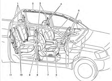
10. Navigation system* (if so equipped)
(P. 4-2)
11. Navigation system* controls
(if so equipped) (P. 4-2)
12. Audio system controls (P. 4-30) 13. Front passenger supplemental air bag
(P. 1-47)
14. Glove box (P. 2-42) 15. Climate controls (P. 4-14, P. 4-21,
WIC1563
P. 4-28)
2-2 Instruments and controls
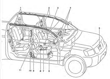
32. Pedal position adjustment switch
(if so equipped) (P. 3-14)
33. Rear power window switch
(if so equipped) (P. 2-51)
*: Refer to the separate Navigation System Own- er’s Manual (if so equipped). See the page number indicated in paren- theses for operating details.
16. Aux jack (if so equipped) (P. 4-52) 17. Power outlet (P. 2-38) 18. Heated seat switch (if so equipped)
(P. 2-35)
19. Cup holder (P. 2-45) 20. Vehicle Dynamic Control (VDC) off
switch (P. 2-36)
21. Tow mode switch (P. 2-38) 22. Electronic locking rear differential
(E-Lock) system switch (if so equipped) (P.2-36)
23. Shift selector (console)
(if so equipped) (P. 5-16)
24. Hazard warning flasher switch (P. 2-33) 25. Front passenger air bag status light
(P. 1-56)
26. Power outlet (P. 2-38) 27. 4WD shift switch (if so equipped)
(P. 5-27)
28. Windshield wiper/washer switch
(P. 2-27)
29. Tilt steering wheel control (P. 3-14) 30. Cargo lamp switch (if so equipped)
(P. 2-34)
31. Rear sonar system off switch
(if so equipped) (P. 2-37)
Instruments and controls 2-3
METERS AND GAUGES
1. Warning/indicator lights 2. 3. 4. 5. 6. 2-4 Instruments and controls
Tachometer Engine coolant temperature gauge Voltmeter (if so equipped) Fuel gauge Speedometer
WIC1243
7.
Automatic transmission fluid tempera- ture gauge (if so equipped)
8. Odometer/Twin trip odometer/Vehicle
9.
Information Display Engine oil pressure gauge (if so equipped)
Speedometer
1. 2. Odometer/twin trip display 3. Change button SPEEDOMETER AND ODOMETER Speedometer The speedometer indicates vehicle speed. Odometer/Twin trip odometer The odometer/twin trip odometer is displayed when the ignition switch is placed in the ON position. The odometer records the total distance the ve- hicle has been driven.
WIC1244
The twin trip odometer records the distance of individual trips.WIC1245
Changing the display: Pushing the change button changes the display as follows:
→ Trip
→ Odometer only
Trip Elapsed time , driving distance and average speed information is also available for vehicles with a navigation system. Refer to “Control panel buttons” in the “Display screen, heater, air condi- tioner, audio and phone systems”. Resetting the trip odometer: Pushing the change button for more than 1 sec- ond resets the currently displayed trip odometer to zero.
Instruments and controls 2-5
CAUTION
If the gauge indicates coolant tempera- ture near the hot (H) end of the normal range, reduce vehicle speed to decrease temperature. If the gauge is over the nor- mal range, stop the vehicle as soon as safely possible. If the engine is over- heated, continued operation of the ve- hicle may seriously damage the engine. See “If your vehicle overheats” in the “In case of emergency” section for immediate action required.
WIC1246
TACHOMETER The tachometer indicates engine speed in revo- lutions per minute (rpm). Do not rev the engine into the red zone 䊊1 .
CAUTION
When engine speed approaches the red zone, shift to a higher gear or reduce en- gine speed. Operating the engine in the red zone may cause serious engine damage.
LIC1135
ENGINE COOLANT TEMPERATURE GAUGE The gauge indicates the engine coolant tempera- ture. The engine coolant temperature is within the normal range 䊊1 when the gauge needle points within the zone shown in the illustration.The engine coolant temperature varies with the outside air temperature and driving conditions.
2-6 Instruments and controls
The located on the driver’s side of the vehicle.
indicates that the fuel-filler door is
CAUTION
● If the vehicle runs out of fuel, the
Malfunction Indicator Light (MIL) may come on. Refuel as soon as possible. light After a few driving trips. the should turn off. If the light remains on after a few driving trips, have the ve- hicle inspected by a NISSAN dealer.
● For additional information, see “Mal- function Indicator Light (MIL)” later in this section.
LIC1199
FUEL GAUGE The gauge indicates the approximate fuel level in the tank.
The gauge may move slightly during braking, turning, acceleration, or going up or down hills.
The gauge needle returns to E (Empty) after the ignition key is turned to OFF.
The low fuel warning light comes on when the amount of fuel in the tank is getting low. Refill the fuel tank before the gauge regis- ters E (Empty).
LIC1198
ENGINE OIL PRESSURE GAUGE (if so equipped) The gauge indicates the engine lubrication sys- tem oil pressure while the engine is running. The needle should be in the middle of the gauge when the engine is running.Instruments and controls 2-7
CAUTION
● This gauge is not designed to indicate low engine oil level. Use the dipstick to check the oil level. (See “Engine oil” in the “Maintenance and do-it-yourself” section.)
● If the gauge needle does not move with the proper amount of engine oil, have the vehicle checked by a NISSAN dealer. Continued vehicle operation in such a condition could cause serious damage to the engine.
2-8 Instruments and controls
LIC1136
VOLTMETER (if so equipped) When the ignition switch is placed in the ON position, the voltmeter indicates the battery volt- age. When the engine is running, it indicates the generator voltage. While cranking the engine, the volts drop below the normal range. If the needle is not in the normal range (11 - 15 volts) 䊊1 while the engine is running, it may indicate that the charging system is not functioning properly. Have the system checked by a NISSAN dealer.
WIC1247
AUTOMATIC TRANSMISSION FLUID TEMPERATURE GAUGE (if so equipped) This gauge indicates the temperature of the au- tomatic transmission fluid. The automatic trans- mission fluid temperature is in the normal range 䊊1 when the gauge needle points within the zone shown in the illustration.CAUTION
● This gauge is not designed to indicate low automatic transmission fluid level. Use the dipstick to check the fluid level. (See “5-speed automatic transmission fluid” in the “Maintenance and do-it- yourself” section.)
● If the gauge indicates automatic trans- mission fluid temperature over the nor- mal range, stop the vehicle as soon as safely possible. Have the vehicle checked by a NISSAN dealer. Contin- ued operation of the vehicle may seri- ously damage the transmission.
COMPASS DISPLAY (if so equipped)
This unit measures terrestrial magnetism and in- dicates the heading direction of the vehicle.
or
With the ignition switch in the ON position, press button as described in the the charts below to activate various features of the automatic anti-glare rearview mirror. Type A
Push and hold the button for about: 1 second
8 seconds
11 seconds
13 seconds Type B
Feature: (Push button again for about 1 sec- ond to change settings) Compass display toggles on/off Automatic anti-glare/indicator light toggles on/off Compass zone can be changed to correct false compass readings Compass enters calibration mode
Push and hold the button for about: 1 second
8 seconds
10 seconds
Feature: (Push button again for about 1 sec- ond to change settings) Compass display toggles on/off Compass zone can be changed to correct false compass readings Compass enters calibration mode
For information about the automatic anti-glare feature, refer to “Automatic anti-glare rearview mirror” in the “Pre-driving checks and adjust- ments” section.
Instruments and controls 2-9
WIC0904
LIC0583
Type A COMPASS DISPLAY
or
Push the button for about 1 sec- ond when the ignition switch is placed in the ON position to toggle the compass direction display 䊊1 on or off. The display will indicate the direction that the vehicle is heading.
Type B
If the display reads “C”, calibrate the compass by driving the vehicle in three complete circles at less than 5 MPH (8 km/h). You can also calibrate the compass by driving your vehicle on your everyday route. The com- pass will be calibrated once it has tracked three complete circles.
N: North E: East S: South W: West
2-10 Instruments and controls
Zone variation change procedure The difference between magnetic north and geo- graphical north is known as variance. In some areas, this difference can sometimes be great enough to cause false compass readings. Follow these instructions to set the variance for your particular location if this happens:
button for about 1. Press and hold the button for about 8
11 seconds or the seconds. The current zone number will ap- pear in the display. Release the button.2. Find your current location on the zone map.
Refer to the illustration.
3. Press the
or the
button repeat- edly to toggle through the zone numbers until the desired number appears in the dis- play. Once you have selected a zone num- ber, the display will show a compass direc- tion within a few seconds.
WIC0355
NOTE: Use zone number 5 for Hawaii. Inaccurate compass direction The compass display is equipped with automatic correction function. If the correct direction is not shown, follow this procedure.
Instruments and controls 2-11
1. With the display turned on, press and hold the button for about 13 seconds or the for about 10 seconds. The “C” or “CAL” icon in the compass display will illu- minate.
2. Calibrate the compass by driving the vehicle in three complete circles at a maximum speed of 5 MPH (8 km/h).
3. After completing the circles,
should return to normal.
the display
CAUTION
● Do not install a ski rack, antenna, etc., which are attached to the vehicle by means of a magnet. They affect the op- eration of the compass.
● When cleaning the mirror, use a paper towel or similar material dampened with glass cleaner. Do not spray glass cleaner directly on the mirror as it may cause the liquid cleaner to enter the mirror housing.
2-12 Instruments and controls
WARNING/INDICATOR LIGHTS AND AUDIBLE REMINDERS
or
Anti-lock Braking System (ABS) warning light
Low fuel warning light
High beam indicator light (Blue)
Automatic transmission check warning light
Low tire pressure warning light
Malfunction indicator light (MIL)
Automatic transmission park warning light
model)
Master warning light (if so equipped)
Security indicator light (if so equipped)
or
Brake warning light
Seat belt warning light and chime
Slip indicator light
Charge warning light
Supplemental air bag warning light
Turn signal/hazard indicator lights
Engine oil pressure low/engine coolant temperature high warning light
Electronic locking rear differential (E-Lock) system on indicator light (if so equipped)
Vehicle Dynamic Control (VDC) off indicator light
4WD warning light (
model)
Front passenger air bag status light
CHECKING BULBS With all doors closed, apply the parking brake and place the ignition switch in the ON position without starting the engine. The following lights will come on:
or
The following lights come on briefly and then go off:
or
If any light fails to come on, it may indicate a burned-out bulb or an open circuit in the electrical system. Have the system repaired promptly.
WARNING LIGHTS For additional information on warnings and indi- cators, see “Vehicle information display” later in this section.
Instruments and controls 2-13
or
Anti-lock Braking System (ABS) warning light
When the ignition switch is placed in the ON position, the Anti-lock Braking System (ABS) warning light illuminates and then turns off. This indicates the ABS is operational.
If the ABS warning light illuminates while the engine is running, or while driving, it may indicate the ABS is not functioning properly. Have the system checked by a NISSAN dealer.
If an ABS malfunction occurs, the anti-lock func- tion is turned off. The brake system then operates normally, but without anti-lock assistance. See “Brake system” in the “Starting and driving” sec- tion.
Automatic Transmission check warning light
When the ignition switch is placed in the ON position, the light comes on for about 2 seconds. If the light comes on at any other time, it may indicate the automatic transmission system is not functioning properly. Have the system checked by a NISSAN dealer.
2-14 Instruments and controls
Automatic transmission park model) warning light (
WARNING
● If the ATP light is ON, this indicates that the automatic transmission P (Park) po- sition will not function and the transfer case is in neutral.
● When parking, always make sure that the 4WD shift indicator light illuminates and the parking brake is set. Failure to engage the transfer position in 2WD, 4H or 4LO could result in the vehicle mov- ing unexpectedly, resulting in serious personal injury or property damage.
● Shift the 4WD switch into the 2WD, 4H or 4LO position again to turn off the ATP warning light when the shift selector to the P position and the ATP warning light is ON. (Before shifting the 4WD switch into the 4LO position, move the shift selector to the N position once, shift the shift selector into P again and make sure the ATP warning light is OFF.)
This light indicates that the automatic transmis- sion parking function is not engaged. If the trans- fer control is not secured in any drive position
while the shift selector is in the P (Park) position, the transmission will disengage and the drive wheels will not lock.
or
Brake warning light
This light functions for both the parking brake and the foot brake systems. Parking brake indicator
When the ignition switch is placed in the ON position, the light comes on when the parking brake is applied. Low brake fluid warning light
When the ignition switch is placed in the ON position, the light warns of a low brake fluid level. If the light comes on while the engine is running with the parking brake not applied, stop the ve- hicle and perform the following:
1. Check the brake fluid level. Add brake fluid as necessary. See “Brake fluid” in the “Main- tenance and do-it-yourself” section of this manual.
2.
If the brake fluid level is correct, have the warning system checked by a NISSAN dealer.
WARNING
● Your brake system may not be working properly if the warning light is on. Driv- ing could be dangerous. If you judge it to be safe, drive carefully to the nearest service station for repairs. Otherwise, have your vehicle towed because driv- ing it could be dangerous.
● Pressing the brake pedal with the en- gine stopped and/or a low brake fluid level may increase your stopping dis- tance and braking will require greater pedal effort as well as pedal travel.
● If the brake fluid level
is below the MINIMUM or MIN mark on the brake fluid reservoir, do not drive until the brake system has been checked at a NISSAN dealer.
Anti-lock Braking System (ABS) warning indicator
When the parking brake is released and the brake fluid level is sufficient, if both the brake warning light and the Anti-lock Braking System (ABS) warning light illuminate, it may indicate the ABS is not functioning properly. Have the brake system checked, and if necessary, repaired by a NISSAN dealer promptly. Avoid high-speed driv-
ing and abrupt braking. (See “Anti-lock Braking System (ABS) warning light” in this section.)
Charge warning light
If this light comes on while the engine is running, it may indicate the charging system is not func- tioning properly. Turn the engine off and check the generator belt. If the belt is loose, broken, missing, or if the light remains on, see a NISSAN dealer immediately.
CAUTION
● Do not ground electrical accessories directly to the battery terminal. Doing so will bypass the variable control sys- tem and the vehicle battery may not charge completely. Refer to “Variable voltage control system” in the “Mainte- nance and do-it-yourself” section later in this manual.
● Do not continue driving if the generator
belt is loose, broken or missing. Engine oil pressure low/ Engine coolant temperature high warning light
This light warns of low engine oil pressure or high engine coolant temperature.
If the light flickers or comes on during normal driving, pull off the road in a safe area, stop the engine and allow it to cool. If the light remains on after checking the oil and coolant, stop the en- gine immediately and call a NISSAN dealer or other authorized repair shop. This light is not designed to indicate a low oil or low coolant level. Check the oil level with the dipstick and check the coolant level on the reservoir. See “Engine oil” and “Checking engine coolant level” in the “Maintenance and do-it-yourself” section of this manual. Also see “If your vehicle overheats” in the “In case of emer- gency” section of this manual.
CAUTION
● Running the engine with the engine oil pressure warning light on could cause serious damage to the engine almost immediately. Such damage is not cov- ered by warranty. Turn off the engine as soon as it is safe to do so.
Instruments and controls 2-15
● If the gauge indicates engine coolant temperature over the normal range, stop the vehicle as soon as safely pos- sible. If the engine is overheated, con- tinued operation of the vehicle may se- riously damage the engine. See “If your vehicle overheats” in the “In case of emergency” section for immediate ac- tion required.
4WD warning light ( model)
The 4WD warning light comes on when the key switch is turned to ON. It turns off soon after the engine is started.
If the engine or vehicle is not functioning properly, the warning light will either remain illuminated or blink. See “4WD warning light” in the “Starting and driving” section.
CAUTION
● If the warning light comes on or blinks during operation, have your vehicle checked by a NISSAN dealer as soon as possible.
2-16 Instruments and controls
● Do not drive on dry hard surface roads in the 4H or 4LO position. If the 4WD warning light turns on when you are driving on dry hard surface roads: – in the 4H position, shift the 4WD shift
switch to 2WD.
– in the 4LO position, stop the vehicle, move the shift selector to the N posi- tion with the brake pedal depressed, and shift the 4WD shift switch to 2WD.
● If the warning light is still on after the above operation, have your vehicle checked by a NISSAN dealer as soon as possible.
Low fuel warning light
This light comes on when the fuel level in the fuel tank is getting low. Refuel as soon as it is conve- nient, preferably before the fuel gauge reaches E (Empty). There will be a small reserve of fuel in the tank when the fuel gauge needle reaches E (Empty).
Low tire pressure warning light
Your vehicle is equipped with a Tire Pressure Monitoring System (TPMS) that monitors the tire pressure of all tires except the spare.
The low tire pressure warning light warns of low tire pressure or indicates that the TPMS is not functioning properly.
After the ignition switch is placed in the ON position, this light illuminates for about 1 second and turns off. Low tire pressure warning:
If the vehicle is being driven with low tire pressure, the warning light will illuminate. A CHECK TIRE PRESSURE warning also appears in the vehicle information display. If you select the tire pressure information in the display (if so equipped), the LOW PRESSURE warning message will be dis- played. The tire pressure for each tire will also be displayed.
When the low tire pressure warning light illuminates, you should stop and adjust the tire pressure of all 4 tires to the recom- mended COLD tire pressure shown on the Tire and Loading Information label located in the driver’s door opening. The low tire pressure warning light does not automati- cally turn off when the tire pressure is ad- justed. After the tire is inflated to the rec- ommended pressure, the vehicle must be driven at speeds above 16 MPH (25 km/h) to activate the TPMS and turn off the low
tire pressure warning light. Use a tire pres- sure gauge to check the tire pressure.
The CHECK TIRE PRESSURE warning is active as long as the low tire pressure warning light remains illuminated.
For additional information, see “Vehicle informa- tion display” in the “Instruments and controls” section and “Tire Pressure Monitoring System (TPMS)” in the “Starting and driving” section and in the “In case of emergency” section. TPMS malfunction:
If the TPMS is not functioning properly, the low tire pressure warning light will flash for approxi- mately 1 minute when the ignition switch is placed in the ON position. The light will remain on after the 1 minute. Have the system checked by a NISSAN dealer. The CHECK TIRE PRESSURE warning does not appear if the low tire pressure warning light illuminates to indicate a TPMS mal- function.
For additional information, see “Tire Pressure Monitoring System (TPMS)” in the “Starting and driving” section and “Tire pressure” in the “Main- tenance and do-it-yourself” section in this manual.
WARNING
● If the light does not illuminate with the ignition switch in the ON position, have the vehicle checked by a NISSAN dealer as soon as possible.
● If the light illuminates while driving, avoid sudden steering maneuvers or abrupt braking, reduce vehicle speed, pull off the road to a safe location and stop the vehicle as soon as possible. Driving with under-inflated tires may permanently damage the tires and in- crease the likelihood of tire failure. Se- rious vehicle damage could occur and may lead to an accident and could re- sult in serious personal injury. Check the tire pressure for all four tires. Adjust the tire pressure to the recommended COLD tire pressure shown on the Tire and Loading Information label located in the driver’s door opening to turn the low tire pressure warning light OFF. If the light still comes on while driving after adjusting the tire pressure, a tire may be flat. If you have a flat tire, re- place it with a spare tire as soon as possible.
● When a spare tire is mounted or a wheel is replaced, tire pressure will not be indicated, the TPMS will not function and the low tire pressure warning light will flash for approximately 1 minute. The light will remain on after 1 minute. Contact your NISSAN dealer as soon as possible for tire replacement and/or system resetting.
● Replacing tires with those not originally specified by NISSAN could affect the proper operation of the TPMS.
CAUTION
● The TPMS is not a substitute for the regular tire pressure check. Be sure to check the tire pressure regularly.
● If the vehicle is being driven at speeds of less than 16 MPH (25 km/h), the TPMS may not operate correctly.
● Be sure to install the specified size of
tires to the 4 wheels correctly.
Instruments and controls 2-17
Master warning light (if so equipped)
This light comes on when various vehicle infor- mation display warnings appear. ● No key warning ● Low fuel warning ● Low windshield-washer fluid warning ● Parking brake release warning ● Door open warning ● Loose fuel cap warning ● Check tire pressure warning
Seat belt warning light and chime
The light and chime remind you to fasten your seat belts. The light illuminates whenever the ignition switch is placed in the ON or START position and remains illuminated until the driver’s seat belt is fastened. At the same time, the chime sounds for about 6 seconds unless the driver’s seat belt is securely fastened.
2-18 Instruments and controls
The seat belt warning light may also illuminate if the front passenger’s seat belt is not fastened when the front passenger’s seat is occupied . For 7 seconds after the ignition switch is placed in the ON position, the system does not activate the warning light for the front passenger. Refer to “Seat belts” in the “Safety—Seats, seat belts and supplemental restraint system” section for precautions on seat belt usage.
Supplemental air bag warning light
When the ignition switch is placed in the ON or START position, the supplemental air bag warn- ing light illuminates for about 7 seconds and then turns off. This means the system is operational. If any of the following conditions occur, the front air bag, side air bag, curtain and rollover air bag, and pretensioner systems need servicing and your vehicle must be taken to a NISSAN dealer: ● The supplemental air bag warning light re-
mains on after approximately 7 seconds.
● The supplemental air bag warning light
flashes intermittently.
● The supplemental air bag warning light does
not come on at all.
Unless checked and repaired, the supplemental restraint system (air bag system) and/or the seat belts with pretensioner system may not function properly. For additional details see “Supplemen- tal restraint system” in the “Safety—Seats, seat belts and supplemental restraint system” section of this manual.
WARNING
If the supplemental air bag warning light is on, it could mean that the front air bag, side air bag, curtain and rollover air bag and/or pretensioner systems will not op- erate in an accident. To help avoid injury to yourself or others, have your vehicle checked by a NISSAN dealer as soon as possible. INDICATOR LIGHTS For additional information on warnings and indi- cators, see “Vehicle information display” later in this section.
Electronic locking rear differential (E-Lock) system on indicator light (if so equipped) This light comes on when the electronic locking rear differential (E-Lock) system clutch is fully engaged.
The indicator light flashes when the system is first turned on. When the system fully engages, the light remains on. If the switch is on and the indicator light continues to flash, the system is not engaged.
For additional information, see “Electronic lock- ing rear differential (E-Lock) system switch” later in this section and “Electronic locking rear differ- ential (E-Lock) system” in the “Starting and driv- ing” section of this manual.
Front passenger air bag status light
The front passenger air bag status light will be lit and the passenger front air bag will be OFF depending on how the front passenger seat is being used.
For front passenger air bag status light operation, see “Front passenger air bag and status light” in the “Safety — Seats, seat belts and supplemental restraint system” section of this manual. High beam indicator light (blue)
This blue light comes on when the headlight high beams are on and goes out when the low beams are selected.
The high beam indicator light also comes on when the passing signal is activated.
Malfunction Indicator Light (MIL)
If this indicator light comes on steady or blinks while the engine is running, it may indicate a potential emission control malfunction.
The Malfunction Indicator Light may also come on steady if the fuel-filler cap is loose or missing, or if the vehicle runs out of fuel. Check to make sure the fuel-filler cap is installed and closed tightly, and that the vehicle has at least 3 gallons (11.4 liters) of fuel in the fuel tank.
light should After a few driving trips, the turn off if no other potential emission control system malfunction exists.
If this indicator light comes on steady for 20
seconds and then blinks for 10 seconds when the engine is not running, it indicates that the vehicle is not ready for an emission control sys- tem inspection/maintenance test. See “Readi- ness for inspection/maintenance (I/M) test” in the “Technical and consumer information” section of this manual.Operation
The Malfunction Indicator Light will come on in one of two ways: ● Malfunction Indicator Light on steady — An emission control system malfunction has been detected. Check the fuel-filler cap if the LOOSE FUEL CAP warning appears in the vehicle information display. If the fuel- filler cap is loose or missing, tighten or install the cap and continue to drive the vehicle. light should turn off after a few The driving trips. If the light does not turn off after a few driving trips, have the vehicle inspected by a NISSAN dealer. You do not need to have your vehicle towed to the dealer.
● Malfunction Indicator Light blinking — An engine misfire has been detected which may damage the emission control system. To re- duce or avoid emission control system dam- age: – do not drive at speeds above 45 MPH
(72 km/h).
– avoid hard acceleration or deceleration. – avoid steep uphill grades. – if possible, reduce the amount of cargo
being hauled or towed.
Instruments and controls 2-19
The Malfunction Indicator Light may stop blinking and come on steady. Have the vehicle inspected by a NISSAN dealer. You do not need to have your vehicle towed to the dealer.
CAUTION
Continued vehicle operation without hav- ing the emission control system checked and repaired as necessary could lead to poor driveability, reduced fuel economy, and possible damage to the emission con- trol system.
Security indicator light (if so equipped)
This light blinks whenever the ignition switch is in the LOCK, OFF or ACC position. This function indicates the security system equipped on the vehicle is operational.
For additional tems” later in this section.
information, see “Security sys-
Slip indicator light
This indicator will blink when the VDC system or the traction control system is operating, thus alerting that the vehicle is nearing its traction limits. The road surface may be slippery.
2-20 Instruments and controls
Turn signal/hazard indicator lights
The appropriate light flashes when the turn signal switch is activated.
Both lights flash when the hazard switch is turned on.
Vehicle Dynamic Control (VDC) off indicator light
This indicator light comes on when the Vehicle Dynamic Control off switch is pushed to OFF, the transfer case is in the 4LO position ( model), or when the Vehicle Dynamic Control system is not functioning properly. This indicates the Vehicle Dynamic Control system is not oper- ating.
Push the Vehicle Dynamic Control off switch again or restart the engine and the system will operate normally. See “Vehicle Dynamic Control (VDC) system” in the “Starting and driving” sec- tion of this manual.
The Vehicle Dynamic Control light also comes on when you place the ignition switch in the ON position. The light will turn off after about 2 sec- onds if the system is operational. If the light stays indicator on or comes on along with the
light while you are driving, have the Vehicle Dy- namic Control system checked by a NISSAN dealer. While the Vehicle Dynamic Control system is operating, you might feel slight vibration or hear the system working when starting the vehicle or accelerating, but this is normal. The VDC system will be disabled and the VDC light will illuminate when the electronic locking rear differential (E-lock) system switch (if so equipped) is turned on and the E-lock system is engaged. If the E-lock system disengages or the switch is turned off, the VDC system will be enabled and the VDC light will turn off. AUDIBLE REMINDERS Brake pad wear warning The disc brake pads have audible wear warnings. When a disc brake pad requires replacement, it makes a high pitched scraping sound when the vehicle is in motion, whether or not the brake pedal is depressed. Have the brakes checked as soon as possible if the warning sound is heard. Key reminder chime A chime sounds if the driver’s door is opened while the key is left in the ignition switch. Remove the key and take it with you when leaving the vehicle.
VEHICLE INFORMATION DISPLAY (if so equipped)
Light reminder chime With the ignition switch placed in the OFF posi- tion, a chime sounds when the driver’s door is opened if the headlights or parking lights are on. Turn the headlight control switch off before leav- ing the vehicle.
WIC1248
The vehicle information display 䊊1 is located to the left of the speedometer. It displays such items as: ● automatic transmission position indicator ● cruise control system information (if soequipped)
● some indicators and warnings
WIC1249
HOW TO USE THE VEHICLE INFORMATION DISPLAY Press the vehicle information display INFO but- ton 䊊1 located on the instrument panel to toggle through the following modes. MPG → Range → Warning Rotate the INFO button 䊊2 to highlight the de- sired menu option within the selected mode. Press the INFO button 䊊1 to enter the high- lighted menu.
Instruments and controls 2-21
The icons at the bottom of the display screen show the options available:
ENTER — Press the INFO button to select
a highlighted option.
NEXT — Rotate the INFO button to high-
light an option.
2-22 Instruments and controls
WIC1166
Warning mode (if so equipped) The warning mode can be selected to view any warnings that may be present. Once the screen is selected you have the option of skipping the warning or viewing it in detail. Warnings can be present for issues such as an open door or low fuel. For more information about potential warnings, see “Vehicle information dis- play warnings and indicators” later in this section.
Vehicle information display warnings and indicators 1. Door open warning 2. Low fuel warning 3. Low windshield-washer fluid warning
4. Parking brake warning
8. 4WD shift indicator (
model)
5. Cruise main switch indicator (if so equipped)
9. Automatic transmission position indicator
6. Cruise set switch indicator (if so equipped)
10. Loose fuel cap warning
7. Transfer 4LO position indicator (
model)
11. Check tire pressure warning
LIC2006
Instruments and controls 2-23
Door open warning
This warning illuminates when a door has been opened and the engine is running. Low fuel warning
This warning illuminates when the fuel level in the fuel tank is getting low. Refuel as soon as it is convenient, preferably before the fuel gauge reaches E (Empty). There will be a small re- serve of fuel in the tank when the fuel gauge needle reaches E (Empty).
Low windshield-washer fluid warning
This warning illuminates when the windshield- washer fluid is at a low level. Add windshield- washer fluid as necessary. See “Windshield- washer fluid” in the “Maintenance and do-it- yourself” section of this manual. Parking brake warning This warning illuminates when the parking brake is set and the vehicle is driven. Cruise main switch indicator (if so equipped) This indicator illuminates when the cruise control main switch is pushed. The indicator turns off when the main switch is pushed again. When the cruise main switch indicator the cruise control system is operational. 2-24 Instruments and controls
illuminates,
Cruise set switch indicator (if so equipped)
This indicator illuminates while the vehicle speed is controlled by the cruise control system. If the indicator blinks while the engine is running, it may indicate the cruise control system is not function- ing properly. Have the system checked by a NISSAN dealer. Transfer 4LO position indicator ( model)
This indicator illuminates when the 4WD shift switch is set in the 4LO position with the ignition switch placed in the ON position.
If the 4WD shift switch is set in the 4LO position and the indicator blinks, stop the vehicle, drive slowly forward and the indicator will turn on.
When you shift between 4H and 4LO, stop the vehicle, move the shift selector to the N (Neutral) position, then depress and turn the 4WD shift switch to 4LO or 4H.
The transfer case may be damaged if you shift the switch while driving.
You cannot move the transfer 4WD shift switch between 4H and 4LO unless you have first stopped the vehicle and moved the shift selector
to N (Neutral). Make sure the transfer 4LO posi- tion indicator illuminates when you shift the 4WD shift switch to 4LO. The indicator may blink while shifting from one drive mode to the other. 4WD shift indicator (
model)
While the engine is running, the 4WD shift indi- cator will illuminate the position selected by the 4WD shift switch. The 4WD shift indicator may blink while shifting from one drive mode to the other. Automatic transmission position indicator When the ignition switch is placed in the ON position, this indicator shows the shift selector position. See “Driving the vehicle” in the “Starting and driving” section of this manual. Loose fuel cap warning This warning appears when the fuel-filler cap is not tightened correctly after the vehicle has been refueled. See “Fuel-filler cap” in the “Pre-driving checks and adjustments” section. Check tire pressure warning This warning appears when the low tire pressure warning light in the meter illuminates and low tire pressure is detected. If this warning appears, stop the vehicle and adjust the tire pressure to
SECURITY SYSTEMS (if so equipped)
the recommended COLD tire pressure shown on the Tire and Loading Information label. See “Low tire pressure warning light” earlier in this section and “Tire Pressure Monitoring System (TPMS)” in the “Starting and driving” section.
LIC0644
Your vehicle may have two types of security sys- tems: ● Vehicle security system (if so equipped) ● NISSAN Vehicle Immobilizer System (if soequipped)
VEHICLE SECURITY SYSTEM (if so equipped) The vehicle security system provides visual and audible alarm signals if someone opens the doors when the system is armed. It is not, however, a motion detection type system that activates when a vehicle is moved or when a vibration occurs.
The system helps deter vehicle theft but cannot prevent it, nor can it prevent the theft of interior or exterior vehicle components in all situations. Al- ways secure your vehicle even if parking for a brief period. Never leave your keys in the ignition, and always lock the vehicle when unattended. Be aware of your surroundings, and park in secure, well-lit areas whenever possible. Many devices offering additional protection, such as component locks, identification markers, and tracking systems, are available at auto supply stores and specialty shops. Your NISSAN dealer may also offer such equipment. Check with your insurance company to see if you may be eligible for discounts for various theft protection features. How to arm the vehicle security system 1. Close all windows. (The system can be armed even if the windows are open.)
2. Remove the from the ignition switch. 3. Close all doors. Lock all doors. The doors can be locked with the key, power door lock switch (if the door is opened, locked and then closed), or with the keyfob.
Instruments and controls 2-25
Keyfob operation:
● Push the
button on the keyfob. All doors lock. The hazard lights flash twice and the horn beeps once to indicate all doors are locked.
● When the
button is pushed with all doors locked, the hazard lights flash twice and the horn beeps once as a re- minder that the doors are already locked.
The horn may or may not beep. Refer to “Silencing the horn beep feature” (vehicles without navigation system) in the “Pre- driving checks and adjustments” section or “Vehicle electronic systems” (vehicles with navigation system) in the “Display screen, heater, air conditioner, audio and phone sys- tems” section.
4. Confirm that the
indicator light comes on. The light stays on for about 30
seconds. The vehicle security system is now pre-armed. After about 30 seconds the ve- hicle security system automatically shifts light begins into the armed phase. The to flash once every 3 seconds. If, during the 30-second pre-arm time period, the door is unlocked by the key or the keyfob, or the ignition switch is placed to ACC or ON, the system will not arm.2-26 Instruments and controls
● If the key is turned slowly when locking the door, the system may not arm. Fur- thermore, if the key is turned beyond the vertical position toward the unlock position to remove the key, the system may be disarmed when the key is re- moved. If the indicator light fails to glow for a period of time, unlock the door once and lock it again.
● Even when the driver and/or passengers are in the vehicle, the system will arm with all doors closed and locked with the ignition switch in the OFF position.
● The lockable bedside storage com- partment (if so equipped) is not pro- tected by the vehicle security system.
Vehicle security system activation The vehicle security system will give the following alarm: ● The headlights blink and the horn sounds
intermittently.
● The alarm automatically turns off after a pe- riod of time. However, the alarm reactivates if the vehicle is tampered with again. The alarm can be shut off by unlocking the driver’s door button with the key or by pressing the on the keyfob.
The alarm is activated by: ● opening a door without using the key or keyfob (even if the door is unlocked by using the inside lock knob or the power door lock switch).
How to stop an activated alarm The alarm stops only by unlocking the driver’s button door with the key or by pressing the on the keyfob. NISSAN VEHICLE IMMOBILIZER SYSTEM (if so equipped) The NISSAN Vehicle Immobilizer System will not allow the engine to start without the use of a registered key.
If the engine fails to start using a registered key (for example, when interference is caused by another registered key, an automated toll road device or automatic payment device on the key ring), restart the engine using the following pro- cedures:
1. Leave the ignition switch in the ON position
for approximately 5 seconds.
2. Turn the ignition switch to the OFF or LOCK position, and wait approximately 10 sec- onds.
3. Repeat steps 1 and 2. 4. Restart the engine while holding the device (which may have caused the interference) separate from the registered key.
If the no start condition re-occurs, NISSAN rec- ommends placing the registered key on a sepa- rate key ring to avoid interference from other devices. Statement related to Section 15 of FCC Rules for NISSAN Vehicle Immobilizer Sys- tem (CONT ASSY — IMMOBILIZER, ANT ASSY — IMMOBILIZER) This device complies with part 15 of the FCC Rules and RSS-210 of Industry Canada. Operation is subject to the follow- ing two conditions; (1) This device may not cause harmful in- terference, and (2) this device must accept any interference received, including inter- ference that may cause undesired opera- tion of the device. CHANGES OR MODIFICATIONS NOT EX- PRESSLY APPROVED BY THE PARTY RE- SPONSIBLE FOR COMPLIANCE COULD VOID THE USER’S AUTHORITY TO OPER- ATE THE EQUIPMENT.
WINDSHIELD WIPER AND WASHER SWITCH
LIC0474
LIC0965
Security indicator light The security indicator light blinks whenever the ignition switch is placed in the LOCK, OFF or ACC position. This function indicates the NISSAN Ve- hicle Immobilizer System is operational. If the NISSAN Vehicle Immobilizer System is mal- functioning, the light will remain on while the ignition switch is placed in the ON position. If the light still remains on and/or the en- gine will not start, see a NISSAN dealer for NISSAN Vehicle Immobilizer System ser- vice as soon as possible. Please bring all registered keys that you have when visiting your NISSAN dealer for service.
SWITCH OPERATION The windshield wiper and washer operates when the ignition switch is in the ON position.
Push the lever down to operate the wiper at the following speed: 䊊1
Intermittent (INT) — intermittent operation can be adjusted by turning the knob toward 䊊A (Slower) or 䊊B (Faster). Also, the inter- mittent operation speed varies in accor- dance with the vehicle speed. (For example, when the vehicle speed is high, the intermit- tent operation speed will be faster.)
Instruments and controls 2-27
REAR WINDOW AND OUTSIDE MIRROR (if so equipped) DEFROSTER SWITCH
CAUTION
● Do not operate the washer continu-
ously for more than 30 seconds. ● Do not operate the washer
if
the
windshield-washer reservoir is empty.
● Do not fill the windshield-washer reser- voir with washer fluid concentrates at full strength. So methyl alcohol based windshield-washer fluid concentrates may permanently stain the grille if spilled with filling the windshield- washer fluid reservoir.
● Pre-mix windshield-washer fluid con- centrates with water to the manufactur- er’s recommended levels before pour- ing the fluid into the windshield-washer reservoir. Do not use the windshield- washer reservoir to mix the windshield- washer fluid concentrate and water.
Type A
LIC0488
To defrost the rear window glass and outside mirrors (if so equipped), start the engine and push the rear window defroster switch on. The rear window defroster light on the switch comes on. Push the switch again to turn the defroster off.
indicator
The rear window defroster automatically turns off after approximately 15 minutes.
NOTE: You can turn on or turn off the driving speed dependent intermittent wiper func- tion for vehicles with navigation system. Refer to “Vehicle electronic systems” in the “Display screen, heater, air conditioner, au- dio and phone systems” section later in this manual. 䊊2
Low (LO) — continuous low speed operation 䊊3 High (HI) — continuous high speed opera-tion
Push the lever up 䊊4 to have one sweep opera- tion (MIST) of the wiper. Pull the lever toward you 䊊5
to operate the washer. The wiper will also operate several times.WARNING
In freezing temperatures the washer solu- tion may freeze on the windshield and obscure your vision which may lead to an accident. Warm the windshield with the defroster before you wash the windshield.
2-28 Instruments and controls
HEADLIGHT AND TURN SIGNAL SWITCH
LIC1173
LIC1158
SIC2745
Type B
NOTE: If the rear power window (if so equipped) is lowered while the defroster switch is on, the rear window defroster will automati- cally shut off. The heated outside mirrors (if so equipped) will remain on. The rear win- dow defroster will automatically turn on when the rear power window is fully closed if the switch is on.
Type C
CAUTION
When cleaning the inner side of the rear window, be careful not to scratch or dam- age the rear window defroster.
Type A
HEADLIGHT CONTROL SWITCH Lighting 䊊1 When turning the switch to the
posi- tion, the front parking, tail, license plate and instrument panel lights come on. 䊊2 When turning the switch to the
posi- tion, the headlights come on and all the other lights remain on.
Instruments and controls 2-29
WIC1250
SIC3019
Type C
Type B
CAUTION
Use the headlights with the engine run- ning to avoid discharging the vehicle battery.
WIC1251
Autolight system (if so equipped) The autolight system allows the headlights to be set so they turn on and off automatically. The autolight system can: ● Turn on the headlights, front parking, tail, license plate and instrument panel lights au- tomatically when it is dark.
● Turn off all the lights when it is light. ● Keep all the lights on for a period of time after you place the ignition switch in the OFF position and all doors are closed.
2-30 Instruments and controls
To turn on the autolight system: 1. Turn the headlight switch to the AUTO posi-
tion 䊊1 .
2. Place the ignition switch in the ON position. 3. The autolight system automatically turns the
headlights on and off.
Initially, if the ignition switch is placed in the OFF position and a door is opened and left open, the headlights remain ON for a period of time. If another door is opened while the headlights are on, then the timer is reset. To turn the autolight system off, turn the switch to the OFF,
position.
, or
LIC0836
Be sure you do not put anything on top of the autolight sensor 䊊1 located on the top side of the instrument panel. The autolight sensor controls the autolight; if it is cov- ered, the autolight sensor reacts as if it is dark out and the headlights will illuminate. If this occurs while parked with the engine off and the ignition switch placed in the ON position, your vehicle’s battery could be- come discharged.WIC1252
Headlight beam select 䊊1 To select the high beam function, push the lever forward. The high beam lights come on and the
light illuminates.
䊊2 Pull the lever back to select the low beam. 䊊3 Pulling and releasing the lever flashes the
headlight high beams on and off.
Battery saver system If the ignition switch is placed in the OFF position while the headlight switch is in the or a period of time.
position, the headlights will turn off after
Instruments and controls 2-31
If the parking brake is applied before the engine is started, the daytime running lights do not illumi- nate. The daytime running lights illuminate when the parking brake is released. The daytime run- ning lights will remain on until the ignition switch is placed in the OFF position.
WARNING
When the daytime running light system is active, tail lights on your vehicle are not on. It is necessary at dusk to turn on your headlights. Failure to do so could cause an accident injuring yourself and others.
WIC1506
INSTRUMENT BRIGHTNESS CONTROL The instrument brightness control operates when the in or AUTO position (with auto- the lights activated). Turn the control to adjust the brightness of instru- ment panel lights when driving at night.
headlight
control
switch
is
After the headlights automatically turn off with the position, headlight switch in the the headlights will illuminate again if the headlight switch is moved to the OFF position and then turned to the
position.
or
or
CAUTION
Even though the battery saver feature au- tomatically turns off the headlights after a period of time, you should turn the head- light switch to the OFF position when the engine is not running to avoid discharging the vehicle battery. DAYTIME RUNNING LIGHT SYSTEM (Canada only) The headlights automatically illuminate at a re- duced intensity when the engine is started with the parking brake released. The daytime running lights operate with the headlight switch in the position. Turn the OFF position or in the headlight switch to the position for full illumination when driving at night.
2-32 Instruments and controls
HAZARD WARNING FLASHER SWITCH
LIC0394
Push the switch on to warn other drivers when you must stop or park under emergency condi- tions. All turn signal lights flash.WARNING
● If stopping for an emergency, be sure to
move the vehicle well off the road.
● Do not use the hazard warning flashers while moving on the highway unless unusual circumstances force you to drive so slowly that your vehicle might become a hazard to other traffic.
● Turn signals do not work when the haz-
ard warning flasher lights are on.
Instruments and controls 2-33
WIC1253
TURN SIGNAL SWITCH Turn signal 䊊1 Move the lever up or down to signal the turning direction. When the turn is com- pleted, the turn signals cancel automatically.
Lane change signal 䊊2 To signal a lane change, move the lever up or down to the point where the indicator light begins to flash, but the lever does not latch.
position.
WIC1254
FOG LIGHT SWITCH (if so equipped) To turn the fog lights on, turn the headlight switch to the position, then turn the fog light switch to the To turn the fog lights on with the headlight switch in the AUTO position (if so equipped), the head- lights must be on, then turn the fog light switch to the To turn the fog lights off, turn the fog light switch to the OFF position. The headlights must be on and the low beams selected for the fog lights to operate. The fog lights automatically turn off when the high beam headlights are selected.position.
CARGO LAMP SWITCH (if so equipped)
HORN
The flashers will operate with the ignition switch placed in any position. Some state laws may prohibit the use of the hazard warning flasher switch while driving.
LIC0616
To turn on the cargo lamp, push the switch down to the ON position. The tailgate lights (if so equipped) will also illuminate when the cargo lamp switch is in the ON position.CAUTION
Be sure to turn the light switch to the OFF position when you leave the vehicle for extended periods of time, otherwise the battery will go dead.
LIC0604
To sound the horn, push near the horn icon of the steering wheel.WARNING
Do not disassemble the horn. Doing so could affect proper operation of the supplemental front air bag system. Tam- pering with the supplemental front air bag system may result in serious personal injury.
2-34 Instruments and controls
HEATED SEAT (if so equipped)
WIC1441
1. Start the engine.
2. Push the LO or HI position of the switch, as desired, depending on the temperature. The indicator light in the switch will illuminate.
The heater is controlled by a thermostat, automatically turning the heater on and off. The indicator light will remain on as long as the switch is on.
3. When the seat is warmed or before you leave the vehicle, be sure to turn the switch off.
WARNING
Do not use or allow occupants to use the seat heater if you or the occupants cannot monitor elevated seat temperatures or have an inability to feel pain in body parts that contact the seat. Use of the seat heater by such people could result in se- rious injury.
CAUTION
● Do not use the seat heater for extended periods or when no one is using the seat.
● Do not put anything on the seat which insulates heat, such as a blanket, cush- ion, seat cover, etc. Otherwise, the seat may become overheated.
● Do not place anything hard or heavy on the seat or pierce it with a pin or similar object. This may result in damage to the heater.
● Any liquid spilled on the heated seat should be removed immediately with a dry cloth.
● When cleaning the seat, never use gasoline, benzine, thinner, or any simi- lar materials.
● If any malfunctions are found or the heated seat does not operate, turn the switch off and have the system checked by your NISSAN dealer.
● The battery could run down if the seat heater is operated while the engine is not running.
Instruments and controls 2-35
VEHICLE DYNAMIC CONTROL (VDC) OFF SWITCH
ELECTRONIC LOCKING REAR DIFFERENTIAL (E-Lock) SYSTEM SWITCH (if so equipped)
LIC1548
The vehicle should be driven with the Vehicle Dynamic Control (VDC) system on for most driv- ing conditions. If the vehicle is stuck in mud or snow, the VDC system reduces the engine output to reduce wheel spin. The engine speed will be reduced even if the accelerator is depressed to the floor. If maximum engine power is needed to free a stuck vehicle, turn the VDC system off. To turn off the VDC system, push the VDC OFF switch. The Push the VDC OFF switch again or restart the engine to turn on the system. See “Vehicle Dy- namic Control (VDC) system” in the “Starting and driving” section. 2-36 Instruments and controlsindicator will come on.
LIC0729
The Electronic Locking Rear Differential (E-Lock) system can help provide added traction if the vehicle is stuck or becoming stuck. To activate the E-Lock system: ● the 4WD switch must be in the 4LO position(4-wheel drive vehicles),
● the vehicle must be stopped or moving at 4
MPH (7 km/h) or less, and
● the E-Lock system switch must be turned
ON.
When the E-Lock switch is turned ON, the indi- cator light will flash until the system engages. However, if all operation conditions listed above are not met or the system becomes disengaged, the indicator light will continue to flash.
The Anti-Lock Brake (ABS) system is disabled and the ABS light illuminates when the E-Lock system is ON. Also, the Vehicle Dynamic Control (VDC) system is disabled and the VDC light illuminates when the E-Lock system is ON.
See “Electronic locking rear differential (E-Lock) system” in the “Starting and Driving” section for further explanation and system limitations.
WARNING
● Never leave the E-Lock system ON when driving on paved or hard-surfaced roads. Turning the vehicle may result in the rear wheels slipping and result in an accident and personal injury. After us- ing the E-Lock system to free the ve- hicle, turn the system OFF.
● Use the E-Lock system only when free- ing a stuck vehicle. Try the 4LO position before using the E-Lock system. Never use the E-Lock system on a slippery road surface such as snow or ice sur- face. Using the E-Lock system when driving in these road conditions may cause unexpected movement of the ve- hicle during engine braking, accelerat- ing or turning, which may result in an accident and serious personal injury.
CAUTION
● After using the E-Lock system, turn the switch OFF to prevent possible damage to driveline components from extended use.
● Do not drive over 12 MPH (20 km/h) when the system is engaged. Doing so could result in possible damage to the driveline.
● Do not turn on the E-lock system while the tires are spinning. Doing so could damage drivetrain components.
REAR SONAR SYSTEM OFF SWITCH (if so equipped)
LIC0471
WARNING
The rear sonar system is a convenience but it is not a substitute for proper back- ing. Always turn and check that it is safe to do so before backing up. Always back up slowly.
The rear sonar system is active when the ignition switch is placed to the ON position and the shift selector is in R (Reverse). When sensors detect obstacles within 5.9 ft (1.8
m) of the rear bumper, a beeping tone is emitted.The rear sonar system can be disabled by push- ing the OFF switch. When the system is disabled, the indicator light on the switch will illuminate. Push the switch again to enable the system. The indicator light will go off. The system will automatically reset the next time the ignition switch is turned on. See “Rear sonar system” in the “Starting and driving” section.
Instruments and controls 2-37
TOW MODE SWITCH
POWER OUTLET
For additional information, refer to “Tow mode” in the “Technical and consumer information” sec- tion later in this manual.
Front row
WIC1404
LIC0594
Tow mode should be used when pulling a heavy trailer or hauling a heavy load. Driving the vehicle in the tow mode with no trailer/load or light trailer/light load will not cause any damage. How- ever, fuel economy may be reduced, and the transmission/engine driving characteristics may feel unusual.Press the tow mode switch to activate tow mode. The indicator light on the tow mode switch illumi- nates when tow mode is selected. Press the tow mode switch again to turn tow mode OFF.
Tow mode is automatically canceled when the ignition switch is placed in the OFF position.
2-38 Instruments and controls
2nd row (if so equipped)
WIC0643
LIC0618
Inside center armrest (if so equipped)
The power outlets are for powering electrical accessories such as cellular telephones.
The power outlets located on the driver’s side of the instrument panel and in the truck box are powered directly by the vehicle’s battery.
The power outlets located on the passenger’s side of the instrument panel, inside the center armrest, and in the 2nd row are powered only when the ignition switch is placed in the ACC or ON position.
Open the cap to use a power outlet.
CAUTION
● The outlet and plug may be hot during
or immediately after use.
● Only certain power outlets are designed for use with a cigarette lighter unit. Do not use any other power outlet for an accessory lighter. See your NISSAN dealer for additional information.
● Do not use with accessories that ex- ceed a 12 volt, 120W (10A) power draw. Do not use double adapters or more than one electrical accessory.
● Use power outlets with the engine running
to avoid discharging the vehicle battery.
● Avoid using power outlets when the air conditioner, headlights or rear window defroster is on.
● Before inserting or disconnecting a plug, be sure the electrical accessory being used is turned OFF.
● Push the plug in as far as it will go. If good contact is not made, the plug may overheat or the internal temperature fuse may open.
● When not in use, be sure to close the cap. Do not allow water or any other liquid to contact the outlet.
Instruments and controls 2-39
STORAGE
LIC0617
LIC0565
LIC0566
Side tray
Center tray (if so equipped)
INSTRUMENT PANEL STORAGE TRAYS
WARNING
Do not place sharp objects in the trays to help prevent injury in an accident or sud- den stop.
The rubber mats can be removed for cleaning.
In truck box (if so equipped)
Do not use the outlet located in the truck box with accessories that exceed 12 volt, 120W (15A) power draw . Do not use double adapters or more than one electrical accessory.
CAUTION
For the power outlet located in the bed of the truck, do not use with accessories that exceed a 12 volt, 120W (15A) power draw. Do not use double adapters or more than one electrical accessory.
2-40 Instruments and controls
LIC1369
LIC1370
LIC1371
CONSOLE BOX (if so equipped) Console box storage trays
Console box storage Pull up on the lever 䊊1 to open the console box lid 䊊2 .
Console box lock Use the master key to lock 䊊1 or unlock 䊊2 the console box.
Instruments and controls 2-41
CENTER ARMREST STORAGE (if so equipped) To access the center armrest storage area, lower the center armrest and lift the lid.
2-42 Instruments and controls
LIC0621
LIC0578
GLOVE BOX Open the glove box by pulling the handle. Use the master key to lock or unlock the glove box lock (if so equipped). The valet key cannot be used.
WARNING
Keep glove box lid closed while driving to help prevent injury in an accident or a sudden stop.
CAUTION
● Do not use for anything other than
sunglasses.
● Do not leave sunglasses in the sun- glasses holder while parking in direct sunlight. The heat may damage the sunglasses.
LIC0567
SUNGLASSES HOLDER (if so equipped) To open the sunglasses holder, push and release.
WARNING
● Keep the sunglasses holder closed
while driving to prevent an accident.
MAP POCKETS
LIC0589
Instruments and controls 2-43
LIC0575
SEATBACK POCKET (if so equipped) The seatback pocket is located on the back of the driver’s seat. The pocket can be used to store maps.Small bin (if so equipped) OVERHEAD CONSOLE (if so equipped)
LIC0568
LIC0569
Medium bin (if so equipped)
Storage bins
WARNING
Keep storage bins closed while driving to help prevent injury in an accident or a sudden stop.
Push the button to open a storage bin. Push the lid up to close.
2-44 Instruments and controls
LIC1372
LIC0620
LIC1373
Front — Type A
Front — Type B
CUP HOLDERS
CAUTION
● Avoid abrupt starting and braking when the cup holder is being used to prevent spilling the drink. If the liquid is hot, it can scald you or your passenger.
● Use only soft cups in the cup holder. Hard objects can injure you in an