- Download PDF Manual
-
interior lights and puddle lights (if so equipped), and activate the panic alarm by using the keyfob from outside the vehicle.
Some settings for the keyfob, such as horn beep, can be adjusted. For vehicles without navigation system, refer to “Silencing the horn beep feature” in this section. For vehicles with navigation sys- tem, refer to “Vehicle electronic systems” in the “Display screen, heater, air conditioner, audio and phone systems” section in this manual.
Pre-driving checks and adjustments 3-7
LPD0242
CHILD SAFETY REAR DOOR LOCK (Crew Cab models only) Child safety locks help prevent the rear doors from being opened accidentally, especially when small children are in the vehicle. The child safety lock levers are located on the edge of the rear doors. When the lever is in the LOCK position, the door can be opened only from the outside.● Do not strike the keyfob sharply against
another object.
● Do not change or modify the keyfob. ● Wetting may damage the keyfob. If the keyfob gets wet, immediately wipe until it is completely dry.
● Do not place the keyfob for an extended period in an area where temperatures exceed 140°F (60°C).
● Do not attach the keyfob with a key
holder that contains a magnet.
● Do not place the keyfob near equip- ment that produces a magnetic field, such as a TV, audio equipment and per- sonal computers.
If a keyfob is lost or stolen, NISSAN rec- ommends erasing the ID code of that key- fob. This will prevent the keyfob from un- authorized use to unlock the vehicle. For information regarding the erasing proce- dure, please contact a NISSAN dealer.
Be sure to remove the key from the vehicle before locking the doors.
The keyfob can operate at a maximum distance of approximately 33 ft (10 m) from the vehicle. The effective distance depends upon the conditions around the vehicle.
As many as 5 keyfobs can be used with one vehicle. For information concerning the purchase and use of additional keyfobs, contact a NISSAN dealer.
The keyfob will not function when: ● the battery is discharged. ● the distance between the vehicle and the
keyfob is over 33 ft (10 m).
The panic alarm will not activate when the key is in the ignition switch.
CAUTION
Listed below are conditions or occur- rences which will damage the keyfob: ● Do not allow the keyfob, which contains electrical components, to come into contact with water or salt water. This could affect the system function.
● Do not drop the keyfob.
3-8 Pre-driving checks and adjustments
LPD0209
HOW TO USE REMOTE KEYLESS ENTRY SYSTEM Locking doors 1. Close all windows.
2. Remove the key from the ignition switch.
3. Close the hood and all doors.
4. Press the
button on the keyfob. All the doors lock. The hazard warning lights flash twice and the horn beeps once to indicate all doors are locked.
● When the
button is pressed with all doors locked, the hazard warning lights flash twice and the horn beeps once as a re- minder that the doors are already locked.
● If a door is open and you press the
button, the doors will lock but the horn will not beep and the hazard warning lights will not flash.
The horn may or may not beep. For vehicles without navigation system, refer to “Silencing the horn beep feature” later in this section. For ve- hicles with navigation system, refer to “How to use the setting button” in the “Display screen, heater, air conditioner, audio and phone systems” section later in this manual.
button on the keyfob again
Press the within 5 seconds. ● All doors unlock. ● The hazard warning lights flash once if all
doors are completely closed.
The interior lights can be turned off without wait- ing 30 seconds by inserting the key into the ignition switch and placing it in the ON or START position, locking the doors with the keyfob or pushing the interior light switch to the OFF posi- tion. Auto relock When the button on the keyfob is pressed, all doors will lock automatically within 1 minute unless one of the following operations is per- formed: ● Any door is opened. ● A key is inserted into the ignition switch and
the switch is cycled from OFF to ON.
Linking the keyfob to automatic drive positioner memory If the vehicle is equipped with automatic drive positioner, the keyfob can be linked to a memory setting. See “Automatic drive positioner” in this section. Pre-driving checks and adjustments 3-9
LPD0210
Unlocking doors
button on the keyfob once.
Press the ● Only the driver’s door unlocks. ● The hazard warning lights flash once if all doors are completely closed with the ignition switch in any position except the ON posi- tion.
● The interior lights and puddle lights (if so equipped) turn on and the light timer acti- vates for 30 seconds when the interior light switch is in the DOOR position with the ignition switch in any position except the ON position.
Using the interior lights button on the keyfob once to Press the turn on the interior lights and puddle lights (if so equipped). For additional information, refer to “Interior light” in the “Instruments and controls” section in this manual.
LPD0262
Silencing the horn beep feature If desired, the horn beep feature can be deacti- vated using the keyfob.
LPD0211
Using the panic alarm If you are near your vehicle and feel threatened, you may activate the panic alarm to call attention button on the by pressing and holding the keyfob for longer than 0.5 seconds. The panic alarm and headlights will stay on for 25
seconds. The panic alarm stops when: ● it has run for 25 seconds, or ● any button is pressed on the keyfob.3-10 Pre-driving checks and adjustments
NOTE: If you change the horn beep and light flash feature with the keyfob, the display screen (if so equipped) will not show the current mode and cannot be used to change the mode. Use the keyfob to return to the pre- vious mode and re-enable the display screen control.
buttons for at least 2 seconds.
To deactivate: Press and hold the and The hazard warning lights will flash 3 times to confirm that the horn beep feature has been deactivated.
buttons for at least 2 seconds
To activate: Press and hold the and once more. The hazard warning lights will flash once and the horn will sound once to confirm that the horn beep feature has been reactivated. Deactivating the horn beep feature does not si- lence the horn if the alarm is triggered.
HOOD
䊊1 Pull the hood lock release handle located below the driver side instrument panel. The hood will spring up slightly.
䊊2 Push the lever at the front of the hood to the side as illustrated with your fingertips and raise the hood.
When closing the hood, lower it slowly and make sure it locks into place.
LPD0244
WARNING
● Make sure the hood is completely closed and latched before driving. Fail- ure to do so could cause the hood to fly open and result in an accident.
● If you see steam or smoke coming from the engine compartment, to avoid injury do not open the hood.
Pre-driving checks and adjustments 3-11
FUEL-FILLER DOOR
FUEL-FILLER CAP
LPD0263
WARNING
● Gasoline is extremely flammable and highly explosive under certain condi- tions. You could be burned or seriously injured if it is misused or mishandled. Always stop the engine and do not smoke or allow open flames or sparks near the vehicle when refueling.
3-12 Pre-driving checks and adjustments
● Do not attempt to top off the fuel tank after the fuel pump nozzle shuts off automatically. Continued refueling may cause fuel overflow, resulting in fuel spray and possibly a fire.
● Use only an original equipment type fuel-filler cap as a replacement. It has a built-in safety valve needed for proper operation of the fuel system and emis- sion control system. An incorrect cap can result in a serious malfunction and possible injury. It could also cause malfunction indicator light the (MIIL) to come on.
● Never pour fuel into the throttle body to
attempt to start your vehicle.
● Do not fill a portable fuel container on a truck bed liner, rubber truck bed mat, or other insulating material. Static elec- tricity can cause an explosion of flam- mable liquid, vapor or gas in any vehicle or trailer. To reduce the risk of serious injury or death when filling portable fuel containers: – Always place the container on the
ground when filling.
– Do not use electronic devices when
filling.
– Keep the pump nozzle in contact with the container while you are fill- ing it.
– Use only approved portable fuel con-
tainers for flammable liquid.
CAUTION
● Only vehicles with the E-85 filler door label can operate on E-85. Fuel system or other damage can occur if E-85 is used in vehicles that are not designed to run on E-85.
● The LOOSE FUEL CAP warning will ap- pear if the fuel-filler cap is not properly tightened. Failure to tighten the fuel- filler cap properly after the LOOSE FUEL CAP warning appears may cause Malfunction Indicator Light the (MIL) to illuminate.
● Failure to tighten the fuel-filler cap Mal- properly may cause the function Indicator Light (MIL) to illumi- light illuminates be- nate. If the cause the fuel-filler cap is loose or missing, tighten or install the cap and to continue vehicle. light should turn off after a The
drive
the
If the
few driving trips. light does not turn off after a few driving trips, have the vehicle inspected by a NISSAN dealer. ● For additional
information, see the “Malfunction Indicator Light (MIL)” in the “Instruments and Controls” section in this manual.
● If fuel is spilled on the vehicle body, flush it away with water to avoid paint damage.
For additional information, see “Fuel recommen- dation (without Flexible Fuel Vehicle option)” and “Flexible fuel vehicle (FFV) fuel recommendation” in the “Technical and consumer information” sec- tion in this manual.
LPD0325
LRS2005
To remove the fuel-filler cap: 1. Turn the fuel-filler cap counterclockwise to
remove.
2. Loop the tether strap around the hook 䊊1
while refueling.
To install the fuel-filler cap: 1.
Insert the fuel-filler cap straight into the fuel- filler tube.
2. Turn the fuel-filler cap clockwise until
it clicks. The fuel-filler cap is a ratcheting type.
Loose Fuel Cap warning The LOOSE FUEL CAP warning appears in the odometer when the fuel-filler cap is not tightened correctly after the vehicle has been refueled. To turn off the warning, do the following: 1. Remove and install the fuel-filler cap as pre-
viously described as soon as possible. 2. Tighten the fuel-filler cap until it clicks. 3. Press the loose fuel cap warning reset but- ton 䊊A in the meter for about 1 second to turn off the LOOSE FUEL CAP warning 䊊B after tightening the fuel-filler cap.
Pre-driving checks and adjustments 3-13
STEERING WHEEL
PEDAL POSITION ADJUSTMENT (if so equipped)
CAUTION
Do not adjust the pedal position with your foot on the pedal.
TILT OPERATION
LPD0254
WARNING
Do not adjust the steering wheel while driving. You could lose control of your vehicle and cause an accident.
Pull the lock lever forward and hold it to adjust the steering wheel up or down to the desired posi- tion. Release the lock lever to lock the steering wheel in place.
LPD0255
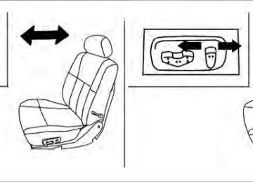
The accelerator and brake pedals can be ad- justed for driving comfort.Use the pedal adjusting switch to adjust the brake and accelerator pedal position away from the driver 䊊1 or toward the driver 䊊2 . The brake and accelerator pedals cannot be ad- justed separately.
WARNING
Do not adjust the pedal position while driving. You can lose control of your ve- hicle and cause an accident.
3-14 Pre-driving checks and adjustments
SUN VISORS
Type B
LPD0264
䊊1 To block glare from the front, swing down the
main sun visor.
䊊2 To block glare from the side, remove the main sun visor from the center mount and swing the visor to the side.
䊊3 To block glare from the side and front, swing
down the sub-sun visor (if so equipped).
䊊4 Slide the extension sun visor (if so equipped)
in or out as needed.
Type A
LPD0273
CAUTION
● Do not store the sun visor before return- ing the extension to its original position.
● Do not pull the extension sun visor forc-
edly downward.
Pre-driving checks and adjustments 3-15
MIRRORS
WPD0168
LPD0257
Type A
VANITY MIRRORS (if so equipped) To access the vanity mirror, pull the sun visor down and flip open the mirror cover (if so equipped). Some vanity mirrors are illuminated and turn on when the mirror cover is open.
Type B
WPD0126
REARVIEW MIRROR (if so equipped) The night position 䊊1 reduces glare from the headlights of vehicles behind you at night. Use the day position 䊊2 when driving in daylight hours.WARNING
Use the night position only when neces- sary, because it reduces rear view clarity.
3-16 Pre-driving checks and adjustments
AUTOMATIC ANTI-GLARE REARVIEW MIRROR (if so equipped) The inside mirror is designed so that it automati- cally dims during night time conditions and ac- cording to the intensity of the headlights of the vehicle following you. The automatic anti-glare feature is activated when the ignition switch is in the ON position. The indicator light will illuminate when the auto- matic anti-glare feature is operating.
NOTE: Do not hang any objects over the sensors 䊊1 or apply glass cleaner to the sensors. Doing so will reduce the sensitivity of the sensors, resulting in improper operation.
For more information about the compass and compass features 䊊2
(if so equipped), see “Compass display” in the “Instruments and con- trols” section of this manual.Type A
LPD0446
Type A With the ignition switch placed in the ON posi- tion, press the ● To turn off
button as described:
the anti-glare feature, press button. The indicator light will turn
the off.
● To turn on the anti-glare feature, press button again. The indicator light
the will turn on.
The indicator light will illuminate when the auto- matic anti-glare feature is operating.
Pre-driving checks and adjustments 3-17
For information on HomeLink姞 Universal Trans- ceiver operation, see “HomeLink姞 Universal Transceiver” in the “Instruments and controls” section of this manual. For information on the compass and compass features 䊊2 , see “Compass display” in the “In- struments and controls” section of this manual. OUTSIDE MIRRORS
WARNING
● Objects viewed in the outside mirror on the passenger side are closer than they appear. Be careful when moving to the right. Using only this mirror could cause an accident. Use the inside mirror or glance over your shoulder to properly judge distances to other objects.
WPD0170
Manual control type (if so equipped) The outside mirror can be moved in any direction for a better rear view.
Type B
LPD0447
Type B With the ignition switch in the ON position, press the ● To turn off the automatic anti-glare feature, button. The indicator light
button as described:
press the will turn off.
● To turn on the automatic anti-glare feature, button again. The indicator
press the light will turn on.
The indicator light will illuminate when the auto- matic anti-glare feature is operating.
3-18 Pre-driving checks and adjustments
The lower portion of the trailer tow mirror can be moved manually in any direction for a better rear view.
LPD0237
LPD0279
Electric control type (if so equipped) The outside mirror remote control will operate only when the ignition switch is placed in the ACC or ON position. Move the small switch 䊊1 to select the right or left mirror. Adjust each mirror to the desired position using the large switch 䊊2 .
Trailer tow mirrors (if so equipped)
WARNING
Objects viewed in the convex portion of the trailer tow mirror are closer than they appear. Be careful when changing lanes or turning. Using only the convex mirror could cause an accident. Use the other mirrors or glance over your shoulder to properly judge distances to other objects.
Use the outside mirror remote control to adjust the top portion of the trailer tow mirror.
Pre-driving checks and adjustments 3-19
Type A
Type B
LPD0259
LPD0269
Manual folding outside mirrors (if so equipped) Pull the outside mirror toward the door to fold it.
LPD0268
Pull the trailer tow mirror outward to extend it to the desired position for better visibility while tow- ing a trailer.WARNING
Do not extend or retract mirrors while driv- ing. You may lose control of your vehicle and cause an accident.
CAUTION
Driving in tight spaces with mirrors ex- tended may cause damage to the vehicle.
3-20 Pre-driving checks and adjustments
Heated mirrors (if so equipped) Some outside mirrors can be heated to defrost, defog, or de-ice for improved visibility. For addi- tional information, see “Rear window and outside mirror defroster switch” in the “Instruments and controls” section of this manual.
push the “OPEN” switch until the mirrors are in the open position. Automatic anti-glare outside mirror (Driver’s side only) (if so equipped) The outside mirror will automatically dim during nighttime conditions to reduce the glare from the headlights of trailing vehicles. The automatic anti- glare feature operates only when the ignition switch is placed in the ON position. The automatic anti-glare feature will be on when starting the vehicle. The indicator light on the automatic anti-glare rearview mirror will illuminate when the automatic anti-glare feature is operat- ing.
To turn off the anti-glare feature, press the button on the rearview mirror. The indicator light will turn off. To turn on the anti-glare feature again, press button on the rearview mirror. The in- the dicator light will turn on. For information on the automatic anti-glare rear- view mirror, see “Automatic anti-glare rearview mirror” in this section.
LPD0196
Power folding outside mirrors (if so equipped)
CAUTION
Do not manually fold the power folding mirrors. Manually folding the mirrors can damage the mirrors.
Push the switch to open or close the mirrors.
If one of the mirrors are manually operated or bumped, the mirror body can become loose at the pivot point. To correct electronic mirror op- eration, cycle the mirrors by pushing the “CLOSE” switch until completely closed, then
Pre-driving checks and adjustments 3-21
For proper truck box loading see “Vehicle loading information” in the “Technical and consumer in- formation” section of this manual.
WARNING
● It is extremely dangerous to ride in a cargo area inside a vehicle. In a colli- sion, people riding in these areas are more likely to be seriously injured or killed.
● Do not allow people to ride in any area of your vehicle that is not equipped with seats and seat belts.
● Be sure everyone in your vehicle is in a
seat and using a seat belt properly.
TRUCK BOX
LPD0270
TAILGATE Opening the tailgate Pull the tailgate handle upward and lower the tailgate. The support cables hold the tailgate open.
When closing the tailgate, make sure the latches are securely locked. Do not drive the vehicle with the tailgate down, unless equipped with NISSAN’s Bed Extender (accessory) or equivalent in the extended position.
3-22 Pre-driving checks and adjustments
Removing the tailgate 1. Release the tailgate support cables.
LPD0271
CAUTION
● The tailgate is heavy. Two people should remove or install it. Be careful not to drop it during removal.
● After releasing the support cables, do not let the tailgate rest on the bumper.
2. Hold the tailgate at a 45 degree angle.
3. Pull the tailgate out from the left side hinge.
4. Slide the tailgate out of the right side hinge.
Installing the tailgate 1. 2. Hold the tailgate at a 45 degree angle and
Insert the tailgate into the right side hinge.
insert into the left side hinge.
3. Continue to hold the tailgate at a 45 degree angle and attach the tailgate support cables.
4. Close the tailgate securely.
LPD0272
LTI0102
Locking the tailgate To unlock the tailgate, turn the key toward the passenger side of the vehicle 䊊1 . To lock, turn the key toward the driver side 䊊2 . Both the master key and the valet key can be used to lock and unlock the tailgate.
TIE DOWN HOOKS For your convenience, tie down hooks are placed at each corner of the truck box. These may be used to help secure cargo loaded into the truck box. ● The weight of the cargo load must be evenly distributed over both the front and the rear axles.
● All cargo should be securely fastened with ropes or straps to prevent it from shifting or sliding within the vehicle.
Pre-driving checks and adjustments 3-23
WARNING
● Properly secure all cargo with ropes or straps to help prevent it from sliding or shifting. In a sudden stop or collision, unsecured cargo could cause personal injury.
AUTOMATIC DRIVE POSITIONER (if so equipped)
The automatic drive positioner system has two features: ● Memory storage function ● Entry/exit function
LPD0260
MEMORY STORAGE FUNCTION Two positions for the driver’s seat, accelerator and brake pedals, and outside mirrors can be stored in the automatic drive positioner memory. Follow these procedures to use the memory sys- tem. 1. Place the shift selector in the P (Park) posi-
tion.
2. Place the ignition switch in the ON position.
3-24 Pre-driving checks and adjustments
3. Adjust
the driver’s seat, accelerator and brake pedals, and outside mirrors to the desired positions by manually operating each adjusting switch. For additional infor- mation, see “Seats” in the “Safety—Seats, seat belts and supplemental restraint sys- tem” section of this manual and “Pedal posi- tion adjustment” and “Outside mirrors” ear- lier in this section.
During this step, do not place the ignition switch in any position other than ON.
4. Push the SET switch and, within 5 seconds,
push the memory switch (1 or 2).
The indicator light for the pushed memory switch will come on and stay on for approxi- mately 5 seconds after pushing the switch. After the indicator light goes off, the se- lected positions are stored in the selected memory (1 or 2).
If a new memory is stored in the same memory switch, the previous memory will be deleted. Linking a keyfob to a stored memory position Each keyfob can be linked to a stored memory position (memory switch 1 or 2) with the follow- ing procedure.
1. Follow the steps for storing a memory posi-
tion.
2. While the indicator light for the memory switch being set is illuminated for 5 sec- button on the keyfob. onds, press the The indicator light will blink. After the indica- tor light goes off, the keyfob is linked to that memory setting.
With the key removed from the ignition switch, button on the keyfob. The driv- press the er’s seat, accelerator and brake pedals, and out- side mirrors will move to the memorized position.
NOTE:
If a new memory position is saved to the memory switch, the keyfob automatically re-links. Confirming memory storage ● Place the ignition switch in the ON position and push the SET switch. If the main memory has not been stored, the indicator light will come on for approximately 0.5 seconds. When the memory has stored the position, the indicator light will stay on for approxi- mately 5 seconds.
● If the battery cable is disconnected, or if the fuse opens, the memory storage function will be canceled and must be restarted before a stored memory position can be set again. Drive the vehicle over 25 MPH (40 km/h) to restart the memory storage function. You can also restart the memory storage function using the following procedure.
1. Connect the battery cable or replace the
fuse.
2. Open and close the driver’s door more than 2 times with the ignition switch in the LOCK position. Once the memory storage function has been restarted, you can store a memory position. See “Memory storage function” in this sec- tion.
Selecting the memorized position Set the shift selector to the P (Park) position, then: ● Within 45 seconds of opening the driver’s
door, push the memory switch (1 or 2) or
● Place the ignition switch in the ON position
and push the memory switch (1 or 2).
Pre-driving checks and adjustments 3-25
The driver’s seat, accelerator and brake pedals, and outside mirrors will move to the memorized position with the indicator light blinking, and then the light will stay on for approximately 5 seconds. ENTRY/EXIT FUNCTION This system is designed so that the driver’s seat will automatically move when the shift selector is placed in the P (Park) position. This allows the driver to get into and out of the driver’s seat more easily. The driver’s seat will slide backward: ● When the key is removed from the ignition
switch and the driver’s door is opened.
● When the driver’s door is opened with the ignition switch placed in the LOCK position. ● When the ignition switch is turned from ACC to LOCK with the driver’s door open. The driver’s seat will return to the previous posi- tion: ● When the key is inserted into the ignition
switch and the driver’s door is closed.
● When the driver’s door is closed with the ignition switch placed in the LOCK position. ● When the ignition switch is turned from ACC to ON while the shift selector is in the P (Park) position.
3-26 Pre-driving checks and adjustments
The entry/exit function can be adjusted or can- celed. For vehicles with a navigation system, see “Vehicle electronic systems” in the “Display screen, heater, air conditioner, audio and phone systems” section of this manual. For vehicles without navigation system, see your NISSAN dealer. Restarting the entry/exit function If the battery cable is disconnected or if the fuse opens, the entry/exit function will be disabled. Drive the vehicle over 25 MPH (40 km/h) to restart the entry/exit function. You can also restart the entry/exit function using the following proce- dure.
1. Connect the battery cable or replace the
fuse.
2. Open and close the driver’s door more than 2 times with the ignition switch in the LOCK position.
The entry/exit function should now work properly. SYSTEM OPERATION The automatic drive positioner system will not work or will stop operating under the following conditions: ● When the vehicle speed is above 4 MPH (7
km/h).
● When any of
the memory switches are pushed while the automatic drive positioner is operating.
● When the adjusting switch for the driver’s seat is turned on while the automatic drive positioner is operating.
● When the seat has already been moved to
the memorized position.
● When no seat position is stored in the
memory switch.
● When the shift selector is moved from P
(Park) to any other position.
● When the driver’s door remains open more than 45 seconds and the ignition switch is not in the ON position.
The automatic drive positioner system can be adjusted and canceled. For vehicles with a navi- gation system, see “Vehicle electronic systems” in the “Display screen, heater, air conditioner, audio and phone systems” section of this manual. For vehicles without navigation system, see your NISSAN dealer.
MEMO
Pre-driving checks and adjustments 3-27
4 Display screen, heater, air conditioner, audio and phone systems
Control panel buttons (if so equipped) . . . . . . . . . . . . . . . 4-2
How to use the joystick and ENTER button . . . . . . . . 4-3
How to use the BACK button . . . . . . . . . . . . . . . . . . . . 4-3
Setting up the start-up screen . . . . . . . . . . . . . . . . . . . 4-3
How to use the TRIP button . . . . . . . . . . . . . . . . . . . . . 4-4
How to use the SETTING button . . . . . . . . . . . . . . . . . 4-7
button. . . . . . . . . . . . . . . . . . . . . . . . . . . . . . . . . . 4-13
Vents . . . . . . . . . . . . . . . . . . . . . . . . . . . . . . . . . . . . . . . . . . . 4-13
Heater and air conditioner (manual) (Type A) (if so equipped) . . . . . . . . . . . . . . . . . . . . . . . . . . . . . . . . . . 4-14
Controls. . . . . . . . . . . . . . . . . . . . . . . . . . . . . . . . . . . . . . 4-14
Heater operation . . . . . . . . . . . . . . . . . . . . . . . . . . . . . . 4-15
Air conditioner operation . . . . . . . . . . . . . . . . . . . . . . . 4-16
Air flow charts. . . . . . . . . . . . . . . . . . . . . . . . . . . . . . . . . 4-17Heater and air conditioner (manual) (Type B) (if so equipped) . . . . . . . . . . . . . . . . . . . . . . . . . . . . . . . . . . 4-21
Controls. . . . . . . . . . . . . . . . . . . . . . . . . . . . . . . . . . . . . . 4-21
Heater operation . . . . . . . . . . . . . . . . . . . . . . . . . . . . . . 4-22
Air conditioner operation . . . . . . . . . . . . . . . . . . . . . . . 4-24
Air flow charts. . . . . . . . . . . . . . . . . . . . . . . . . . . . . . . . . 4-25Heater and air conditioner (automatic) (if so equipped) . . . . . . . . . . . . . . . . . . . . . . . . . . . . . . . . . . 4-28
Automatic operation . . . . . . . . . . . . . . . . . . . . . . . . . . . 4-28Manual operation . . . . . . . . . . . . . . . . . . . . . . . . . . . . . . 4-29
Operating tips. . . . . . . . . . . . . . . . . . . . . . . . . . . . . . . . . 4-29
Servicing air conditioner. . . . . . . . . . . . . . . . . . . . . . . . . . . 4-30
Audio system . . . . . . . . . . . . . . . . . . . . . . . . . . . . . . . . . . . . 4-30
Radio . . . . . . . . . . . . . . . . . . . . . . . . . . . . . . . . . . . . . . . . 4-30
FM radio reception . . . . . . . . . . . . . . . . . . . . . . . . . . . . 4-31
AM radio reception . . . . . . . . . . . . . . . . . . . . . . . . . . . . 4-31
Satellite radio reception (if so equipped) . . . . . . . . . 4-31
Audio operation precautions . . . . . . . . . . . . . . . . . . . . 4-32
FM/AM radio with compact disc (CD) player (if so equipped) . . . . . . . . . . . . . . . . . . . . . . . . . . . . . . . 4-37
FM/AM/SAT radio with compact disc (CD) changer (Type A, B, C, D and E) (if so equipped) . . . . . . . . . . . . . . . . . . . . . . . . . . . . . . . 4-46
CD care and cleaning . . . . . . . . . . . . . . . . . . . . . . . . . . 4-53
Steering wheel switch for audio control (if so equipped) . . . . . . . . . . . . . . . . . . . . . . . . . . . . . . . 4-54
Rear audio controls (if so equipped) . . . . . . . . . . . . . 4-55
Antenna . . . . . . . . . . . . . . . . . . . . . . . . . . . . . . . . . . . . . . 4-56NISSAN mobile entertainment system (MES) (if so equipped) . . . . . . . . . . . . . . . . . . . . . . . . . . . . . . . . . . 4-56
Digital video disc (DVD) player controls . . . . . . . . . . 4-57
Remote control. . . . . . . . . . . . . . . . . . . . . . . . . . . . . . . . 4-58
Flip-down screen . . . . . . . . . . . . . . . . . . . . . . . . . . . . . . 4-58Playing a digital video disc (DVD) . . . . . . . . . . . . . . . 4-60
Care and maintenance . . . . . . . . . . . . . . . . . . . . . . . . . 4-63
How to handle the DVD . . . . . . . . . . . . . . . . . . . . . . . . 4-63
Car phone or CB radio . . . . . . . . . . . . . . . . . . . . . . . . . . . . 4-66
Bluetooth姞 Hands-Free Phone System (if so equipped) . . . . . . . . . . . . . . . . . . . . . . . . . . . . . . . . . . 4-66
Regulatory Information . . . . . . . . . . . . . . . . . . . . . . . . . 4-68Using the system . . . . . . . . . . . . . . . . . . . . . . . . . . . . . . 4-68
Control buttons . . . . . . . . . . . . . . . . . . . . . . . . . . . . . . . 4-70
Getting started . . . . . . . . . . . . . . . . . . . . . . . . . . . . . . . . 4-71
List of voice commands . . . . . . . . . . . . . . . . . . . . . . . . 4-73
Speaker adaptation (SA) mode. . . . . . . . . . . . . . . . . . 4-78
Troubleshooting guide . . . . . . . . . . . . . . . . . . . . . . . . . 4-80WARNING
● Positioning of the heating or air condi- tioning controls and display controls should not be done while driving in or- der that full attention may be given to the driving operation.
● Do not disassemble or modify this sys- tem. If you do, it may result in accidents, fire, or electrical shock.
● Do not use this system if you notice any abnormality, such as a frozen screen or lack of sound. Continued use of the system may result in accident, fire or electric shock.
● In case you notice any foreign object in the system hardware, spill liquid on it, or notice smoke or smell coming from it, stop using the system immediately and contact your nearest NISSAN dealer. Ignoring such conditions may lead to accidents, fire or electrical shock.
CONTROL PANEL BUTTONS (if so equipped)
brightness control button (P. 4-13)
1. 2. BACK (previous) button (P. 4-3)
3. Joystick and ENTER button (P. 4-3)
4. SETTING button (P. 4-7)
5. TRIP button (P. 4-4)
6. DEST button*
7. ROUTE button*
8. MAP button*
WHA0854
4-2 Display screen, heater, air conditioner, audio and phone systems
9. GUIDE VOICE button*
10.
11.
zoom out button*
zoom in button*
*For Navigation system control buttons, refer to the separate Navigation System Owner’s Manual (if so equipped).
CAUTION
● The glass screen on the liquid crystal display may break if it is hit with a hard or sharp object. If the glass breaks, do not touch the liquid crystalline material, which contains a small amount of mer- cury. In case of contact with skin, wash immediately with soap and water.
● To clean the display, never use a rough cloth, alcohol, benzine, thinner or any kind of solvent or paper towel with a chemical cleaning agent. They will scratch or deteriorate the panel.
● Do not splash any liquid such as water or car fragrance on the display. Contact with liquid will cause the system to malfunction.
When you use this system, make sure the engine is running.
If you use the system with the engine not running (ignition ON or ACC) for a long time, it will use up all the battery power, and the engine will not start. Reference symbols: ENTER button — This is a button on the control panel. “Display” key — This is a select key on the screen. By selecting this key you can proceed to the next function. HOW TO USE THE JOYSTICK AND ENTER BUTTON Use the joystick to choose an item on the display screen. Move the joystick up, down, left or right to highlight an item. Then press the ENTER button to select the item or perform the action. HOW TO USE THE BACK BUTTON This button has two functions. ● Go back to the previous display (cancel). If you press the BACK button during setup, the setup will be canceled and/or the display will return to the previous screen. ● Finish setup. In some screens pressing the BACK button ac- cepts the changes made during setup.
SETTING UP THE START-UP SCREEN When you place the ignition switch in the ACC or ON position, the system start-up warning is dis- played on the screen. Read the warning and select the “OK” key by pressing the ENTER but- ton. If you do not press the ENTER button, the Navi- gation system will not proceed to the next step in the Navigation display. If you do not touch a button or screen key for more than 1 minute on the system start-up warn- ing screen, the screen will change to the audio screen automatically. To proceed to the next step, refer to the separate Navigation System Owner’s Manual.
Display screen, heater, air conditioner, audio and phone systems 4-3
● Average Speed - Average speed driven
(MPH or km/h) since the last reset.
Resetting trip 1 and trip 2
Each trip screen can be reset to 0. Press the TRIP button to select the TRIP screen to be reset. ● Select the “Reset” key on screen by press-ing the ENTER button, or
● Press the TRIP button for more than approxi-
mately 1.5 seconds.
LHA0552
HOW TO USE THE TRIP BUTTON When the TRIP button is pressed, the following modes will display on the screen. Warning message (if any) → TRIP 1 → TRIP 2 → FUEL ECONOMY → MAINTENANCE → Audio or OFF → TRIP 1
Each trip display tracks an independent trip and displays the following: ● Elapsed Time - Journey time since the last reset up to a maximum of 99 hours and 59
minutes.● Driving Distance - Distance driven (mile or
km) since the last reset.
4-4 Display screen, heater, air conditioner, audio and phone systems
LHA0553
Fuel economy Press the TRIP button to display Average Fuel Economy and Distance To Empty. Average fuel economy (MPG or L/100 km)
The Average Fuel Economy is calculated based on fuel consumption since the last reset. The display is updated every 30 seconds and 1/3
mile (500 m). After a reset or connecting the battery cables, the display will show (**.*).Resetting fuel economy The average fuel economy calculation can be reset to 0. Press the TRIP button repeatedly until the FUEL ECONOMY menu is shown, then ei- ther: ● Select the “Reset” key on screen by press-
ing the ENTER button, or
● Press the TRIP button for more than approxi-
mately 1.5 seconds.
Distance to empty (MI or km) The Distance To Empty (DTE) mode provides you with an estimation of the distance that can be driven before refueling. The DTE is constantly calculated based on the amount of fuel in the fuel tank and the actual fuel consumption. The display is updated every 30 seconds. When the fuel level is low, the DTE display will change to (*).
NOTE: ● If the amount of fuel added while the ignition switch is in the OFF position is small, the display just before the ignition switch is placed in the OFF position may continue to be displayed.
● When driving uphill or rounding curves, the fuel in the tank shifts, which may momentarily change the display.
LHA0554
LHA0555
Maintenance items Press the TRIP button to display maintenance information or set maintenance intervals for the following: ● Engine Oil ● Tire Rotation ● Tire Pressure (if so equipped) For setting the Tire Pressure display, refer to “Tire pressure information” later in this section.
Changing the maintenance interval Select the “Engine Oil” or “Tire Rotation” key using the joystick and press the ENTER button to display the screen to change the maintenance interval. Select the “Maintenance Schedule” key using the joystick and move the joystick to right or left to set the maintenance interval.
Display screen, heater, air conditioner, audio and phone systems 4-5
● The ignition switch is placed in the ON po- sition the next time the vehicle will be driven. To return to the previous display after the MAIN- TENANCE NOTICE screen is displayed, press the BACK button. The MAINTENANCE NOTICE screen displays each time the key is turned ON until one of the following conditions are met: ● “Reset” key is selected. ● “Display Maintenance Notification” is set to
OFF.
LHA0483
● The maintenance interval is set again.
Displaying the maintenance notice re- minder
Select the “Display Maintenance Notification” key and press the ENTER button to display the MAINTENANCE INFORMATION automatically at the set maintenance interval.
The MAINTENANCE NOTICE screen (ENGINE OIL and TIRE ROTATION) will be automatically displayed as shown when both of the following conditions are met: ● The vehicle is driven the set distance and the ignition switch is placed in the OFF position.
LHA0556
Resetting the maintenance interval The ENGINE OIL and TIRE ROTATION mainte- nance intervals can be reset to 0 miles (kilome- ters). Select the “Reset” key using the joystick and press the ENTER button.
4-6 Display screen, heater, air conditioner, audio and phone systems
Tire pressure rises and falls depending on the heat caused by the vehicle’s operation and the outside temperature. In case of low tire pressure, a message is dis- played on the screen: LOW PRESSURE — Check All Tires.
WARNING
● When a spare tire is mounted or a wheel is replaced, tire pressure will not be indicated, the Tire Pressure Monitoring System (TPMS) will not function and the low tire pressure warning light will flash for approximately 1 minute. The light will remain on after 1 minute. Con- tact your NISSAN dealer as soon as possible for tire replacement and/or system resetting.
● Replacing tires with those not originally specified by NISSAN could affect the proper operation of the TPMS.
LHA0558
HOW TO USE THE SETTING BUTTON When the SETTING button is pressed, the SET- TINGS screen will appear on the display. You can select and/or adjust several functions, features and modes that are available for your vehicle. Move the joystick and press the ENTER button to select each item to be set.
Display screen, heater, air conditioner, audio and phone systems 4-7
LHA0557
Tire pressure information To display tire pressure information, press the TRIP button repeatedly until the MAINTENANCE screen is displayed. Select the “Tire Pressure” key using the joystick and press the ENTER but- ton.
Pressure indication in ** psi on the screen indi- cates that the pressure is being measured. After a few driving trips, the pressure for each tire will be displayed randomly.
The order of tire pressure figures displayed on the screen does not correspond with the actual order of the tire position.
WHA0855
WHA0716
LHA0642
Display settings Select the “Display” key and press the ENTER button. The DISPLAY SETTINGS screen will ap- pear.
Brightness/contrast: Select the “Brightness/Contrast” key to adjust the brightness and contrast of the map back- ground. Use the joystick to adjust the brightness to darker or brighter and the contrast to lower or higher. The new settings are automatically saved when you exit the setting screen by pressing the BACK button or any other mode button.
Display off: Select the “Display Off” key. The indicator of the “Display Off” turns amber and the message above will be displayed briefly. When the audio, HVAC (Heater and air conditioner), or any mode button on the control panel is operated, the dis- play turns on for that operation. If one of the control panel buttons is pressed, the display will not automatically turn off until that operation is finished. Otherwise, the screen turns off auto- matically after 5 seconds.
4-8 Display screen, heater, air conditioner, audio and phone systems
To turn the screen on, ● Press the SETTING button and select the “Display” key and then select the “Display Off” key. Then set the screen to on by press- ing the ENTER button, or
● Hold the
button for approximately 2
seconds and the message “resuming dis- play” will appear and the “Display Off” key will be automatically turned on (no amber indicator).LHA0559
Vehicle electronic systems Select the “Vehicle Electronic Systems” key by using the joystick and pressing the ENTER but- ton. The VEHICLE ELECTRONIC SYSTEMS screen will be displayed.
You can set the following operating conditions by selecting the desired item using the joystick, then pressing the ENTER button. The indicator light, box at the left of the selected item, alternately turns on and off each time the ENTER button is pressed.
Indicator light is illuminated — ON Indicator light is not illuminated — OFF
LHA0564
Adjust Driver Seat When Exiting Vehicle: Select so the driver’s seat automatically moves back and returns to the original position for ease of exit and entry. Remote Unlock Driver’s Door First: Select to change which doors will unlock first during an unlocking operation: Only the driver’s door ←→ All the doors Keyless Remote Response — Horn: Select to turn on or turn off the horn chirp mode used when the LOCK button on the keyfob is pressed.Display screen, heater, air conditioner, audio and phone systems 4-9
NOTE:
If you change the horn beep or the lamp flash feature with the keyfob, the mode will not be changed with the display. Use the keyfob to return to the previous mode and re-enable the display control. Auto Re-Lock Time: Select to set the length of time before doors automatically re-lock. Sensitivity of Automatic Headlights: Select to change the sensitivity setting of the automatic headlights: ● Lower: less sensitive, automatic headlights will take longer to come on when the head- light sensor senses less ambient light.
● Higher: more sensitive, automatic headlights will come on quicker when the headlight sensor senses less ambient light.
Automatic Headlights Off Delay: Select to change the setting for the length of time the automatic headlights remain on after exiting the vehicle. Speed Dependent Wiper: Select to turn on or turn off the driving speed dependent intermittent wiper function. Return All Settings to Default: Select to change all VEHICLE ELECTRONICS SYSTEMS to their default settings.
LHA0561
System settings Select the “System Settings” key by using the joystick and pressing the ENTER button. The SYSTEM SETTINGS screen will be displayed. Language/unit
The LANGUAGE/UNIT screen will appear when selecting the “Language/Unit” key and pressing the ENTER button.
Language: English or French
Unit: US — mile, °F, MPG
Metric — km, °C, L/100 km
LHA0565
NOTE:
If you change the horn beep or the lamp flash feature with the keyfob, the display screen will not show the current mode. Use the keyfob to return to the previous mode and re-enable the display screen control.
Keyless Remote Response — Lights: Select to turn on or turn off the hazard indicator flash mode used when the LOCK or UNLOCK button on the keyfob is pressed.
4-10 Display screen, heater, air conditioner, audio and phone systems
You can select the language and unit using the joystick or pressing the ENTER button. The settings are automatically saved when you exit the menu by pressing the BACK button or any other mode button.
LHA0562
LHA0566
Clock Adjusting the time: Select the “Hours” or “Minutes” key and move the joystick to the right or left to adjust the time. The time will change step by step. The new settings are automatically saved when you exit the setting screen by pressing the BACK button or any other mode button.
Setting daylight savings time: Use the “Daylight Saving Time” key to adjust the clock to daylight savings time. ON: Automatically adjusts for daylight savings time. OFF: The current time is displayed.
Display screen, heater, air conditioner, audio and phone systems 4-11
LHA0567
LHA0568
Adjusting the time to the GPS: Select the “Auto Adjust” key. The time will be reset to the GPS time.
Selecting the time zone: 1. Select the “Select Time Zone” key. The TIME ZONE screen will appear.
LHA0563
2. Select one of the following zones, depend-ing on the current location. ● Pacific zone ● Mountain zone ● Central zone ● Eastern zone ● Atlantic zone ● Newfoundland zone
After selection, the CLOCK SETTINGS screen will appear.
4-12 Display screen, heater, air conditioner, audio and phone systems
The GPS time (manual time) corresponding to the selected zone will be displayed. Pacific zone has been set as the initial (default) setting. Beep setting With this option ON, a beep will sound if any audio button is pressed. Navigation settings Refer to the separate Navigation System Own- er’s Manual for information regarding these set- tings. Guidance voice settings Refer to the separate Navigation System Own- er’s Manual for information regarding these set- tings.
BUTTON
To change the display brightness, press the button. Pressing the button again will change the display to “DAY” or “NIGHT” display. Then, adjust the brightness by moving the joy- stick right or left. If no operation is done within 10 seconds, or if the BACK button is pressed, the display will return to the previous display.
VENTS
Adjust air flow direction for the driver’s and pas- senger’s side vents 䊊1 , center vents 䊊2 , and rear passengers’ (if so equipped) vents 䊊3 by moving the vent slide and/or vent assemblies.
WHA1128
Display screen, heater, air conditioner, audio and phone systems 4-13
HEATER AND AIR CONDITIONER (manual) (Type A) (if so equipped)
WARNING
● The air conditioner cooling function op- erates only when the engine is running. ● Do not leave children or adults who would normally require the assistance of others alone in your vehicle. Pets should also not be left alone. They could accidentally injure themselves or others through inadvertent operation of the vehicle. Also, on hot, sunny days, temperatures in a closed vehicle could quickly become high enough to cause severe or possibly fatal injuries to people or animals.
● Do not use the recirculation mode for long periods as it may cause the interior air to become stale and the windows to fog up.
Fan speed control dial Front window defroster button Rear window defroster button Air recirculation button Temperature control dial
1. 2. 3. 4. 5. 6. Max A/C button 7. 8.
Air flow control buttons Air conditioner ON/OFF button
Type A
WHA1406
CONTROLS Fan control dial The fan control dial turns the fan on and off, and controls fan speed. Air flow control buttons The air flow control buttons allow you to select the air flow outlets.
4-14 Display screen, heater, air conditioner, audio and phone systems
MAX A/C — Air flows from center and side
vents with maximum cooling (air conditioning).
— Air flows from center and side
vents.
— Air flows from center and side
vents and the front and rear floor outlets.
— Air flows mainly from the front
and rear floor outlets.
— Air flows from defroster out-
lets and the front and rear floor outlets. Temperature control dial The temperature control dial allows you to adjust the temperature of the outlet air. To lower the temperature, turn the dial to the left. To increase the temperature, turn the dial to the right.
Air recirculation button
ON position: Push the the vehicle.
button to recirculate air inside
Push the ● driving on a dusty road.
button to the on position when:
● to prevent traffic fumes from entering pas-
senger compartment.
● for maximum cooling when using the air con-
ditioner.
or
The air recirculation mode is only functional when the air flow control mode is in the following positions: OFF position: button again to turn air recircula- Push the tion off. Outside air is drawn into the passenger compartment and distributed through the se- lected outlet. Use the off position for normal heater or air con- ditioner operation.
Air conditioner button
Start the engine, turn the fan control dial to the desired position and push the button to turn on the air conditioner. The indicator light comes on when the air conditioner is operating. To turn off the air conditioner, push the button again. The air conditioner cooling function oper- ates only when the engine is running.
HEATER OPERATION Heating This mode is used to direct heated air to the foot outlets. Some air also flows from the defrost outlets.
1. Press the
button to the OFF position for normal heating. The indicator light on the
button will go off.
2. Press the
air flow control button.
3. Turn the fan control dial to the desired position.
4. Turn the temperature control dial to the de- sired position between the middle and the hot position.
Ventilation This mode directs outside air to the side and center ventilators.
1. Press the
The indicator light on the go off.
button to the OFF position. button will
2. Press the 3. Turn the fan control dial to the desired position.
air flow control button.
4. Turn the temperature control dial to the de-
sired position.
Display screen, heater, air conditioner, audio and phone systems 4-15
Defrosting or defogging This mode directs the air to the defrost outlets to defrost/defog the windows. 1. Turn the air flow control dial to the
position.
2. Turn the fan control dial to the desired position. 3. Turn the temperature control dial to the de- sired position between the middle and the hot position.
● To quickly remove ice or fog from the windows, turn the fan control dial to the right and the temperature control to the full HOT position.
● When the
position is selected, the air conditioner automatically turns on (however, button will the indicator light on the not come on) if the outside temperature is more than 36°F (2°C). If in defrost mode for more than one minute, the air conditioning system will continue to operate until the ve- hicle is shut off, the fan is turned off or the A/C button is used to turn off the compres- sor, even if the air flow control dial is turned position. to a position other than the This dehumidifies the air which helps defog mode automati- the windshield. The cally turns off, allowing outside air to be drawn into the passenger compartment to further improve the defogging performance.
Bi-level heating The bi-level mode directs warmed air to the side and center vents and to the front and rear floor outlets.
1. Press the
The indicator light on the go off.
button to the OFF position. button will
2. Press the
air flow control button.
3. Turn the fan control dial to the desired posi-
tion.
4. Turn the temperature control dial to the de-
sired position.
Heating and defogging This mode heats the interior and defogs the wind- shield.
1. Press the
air flow control button.
2. Turn the fan control dial to the desired posi-
tion.
3. Turn the temperature control dial to the de- sired position between the middle and the hot position.
● When the
position is selected, the air conditioner automatically turns on (however, button will the indicator light on the not come on) if the outside temperature is more than 36°F (2°C). If in defrost mode for more than one minute, the air conditioning system will continue to operate until the ve- hicle is shut off, the fan is turned off or the A/C button is used to turn off the compres- sor, even if the air flow control dial is turned position. to a position other than the This dehumidifies the air which helps defog mode automati- the windshield. The cally turns off, allowing outside air to be drawn into the passenger compartment to further improve the defogging performance.
Operating tips Clear snow and ice from the wiper blades and air inlet in front of the windshield. This improves heater operation. AIR CONDITIONER OPERATION Start the engine, turn the fan control dial to the button to desired position, and push in the activate the air conditioner. When the air condi- tioner is on, cooling and dehumidifying functions are added to the heater operation.
4-16 Display screen, heater, air conditioner, audio and phone systems
The air conditioner cooling function oper- ates only when the engine is running. Cooling This mode is used to cool and dehumidify the air.
1. Press the
button to the OFF position.
2. Press the
air flow control button.
3. Turn the fan control dial to the desired posi-
tion.
4. Press the
button. The indicator light
on the
button will come on.
5. Turn the temperature control dial to the de-
sired position.
● For quick cooling when the outside tem- button to light on button will come on. Be sure to to the OFF position for nor-
perature is high, push the the ON position. The indicator the return the mal cooling. The indicator light on the button will go off. You may also select MAX A/C for quick cooling. Dehumidified heating This mode is used to heat and dehumidify the air.
1. Press the
The indicator light on the go off.
button to the OFF position. button will
2. Press the
air flow control button.
3. Turn the fan control dial to the desired posi-
tion.
4. Press the light on the
button on. The indicator button will come on.
5. Turn the temperature control dial to the de-
sired position. Operating tips ● Keep the windows closed while the air con-
ditioner is in operation.
● After parking in the sun, drive for 2 or 3
minutes with the windows open to vent hot air from the passenger compartment. Then, close the windows. This allows the air con- ditioner to cool the interior more quickly.● The air conditioning system should be operated for approximately 10 minutes at least once a month. This helps pre- vent damage to the system due to lack of lubrication.
● A visible mist may be seen coming from the ventilators in hot, humid conditions as the air is cooled rapidly. This does not indicate a malfunction.
● If
the engine coolant
temperature gauge indicates engine coolant tem- perature over the normal range, turn the air conditioner off. See “If your vehicle overheats” in the “In case of emergency” section of this manual.
AIR FLOW CHARTS The following charts show the button and dial positions for MAXIMUM AND QUICK heating, cooling or defrosting. For additional information on heating and cooling see “Heater and air con- ditioner” in this section. The air recirculation ) button should always be in the OFF position for heating and defrosting.
Display screen, heater, air conditioner, audio and phone systems 4-17
4-18 Display screen, heater, air conditioner, audio and phone systems
Type A
Type A
WHA0916
WHA0917
Type A
Display screen, heater, air conditioner, audio and phone systems 4-19
Type A
WHA0918
WHA0919
4-20 Display screen, heater, air conditioner, audio and phone systems
Type A
WHA1362
HEATER AND AIR CONDITIONER (manual) (Type B) (if so equipped)
WARNING
● The air conditioner cooling function op- erates only when the engine is running. ● Do not leave children or adults who would normally require the assistance of others alone in your vehicle. Pets should also not be left alone. They could accidentally injure themselves or others through inadvertent operation of the vehicle. Also, on hot, sunny days, temperatures in a closed vehicle could quickly become high enough to cause severe or possibly fatal injuries to people or animals.
● Do not use the recirculation mode for long periods as it may cause the interior air to become stale and the windows to fog up.
Type B
WHA0535
1. 2. 3. 4. 5. 6.
Fan speed control dial Air recirculation button Temperature control dial Air conditioner button Air flow control dial Rear window defroster switch (if so equipped) CONTROLS Fan control dial The fan control dial turns the fan on and off, and controls fan speed.
Air flow control dial The air flow control dial allows you to select the air flow outlets. MAX A/C
— Air flows from center and side
vents with maximum cooling (air conditioning).
— Air flows from center and side
vents.
— Air flows from center and side
vents and the front and rear floor outlets.
Display screen, heater, air conditioner, audio and phone systems 4-21
— Air flows mainly from the front and
rear floor outlets.
— Air flows from defroster outlets
and the front and rear floor outlets.
— Air flows mainly from defroster
outlets.
The air flow control dial also has intermediate positions which allow the air flow to be distrib- uted between 2 of the icon positions on the air flow control dial. Temperature control dial The temperature control dial allows you to adjust the temperature of the outlet air. To lower the temperature, turn the dial to the left. To increase the temperature, turn the dial to the right.
Air recirculation button
ON position: Push the the vehicle.
button to recirculate air inside
button to the on position when:
Push the ● driving on a dusty road. ● to prevent traffic fumes from entering pas-
senger compartment.
● for maximum cooling when using the air con-
ditioner.
or
The air recirculation mode is only functional when the air flow control mode is in the following positions: OFF position: button again to turn air recircula- Push the tion off. Outside air is drawn into the passenger compartment and distributed through the se- lected outlet. Use the off position for normal heater or air con- ditioner operation.
Air conditioner button
Start the engine, turn the fan control dial to the desired position and push the button to turn on the air conditioner. A/C will appear on the display when the air conditioner is operating. To button turn off the air conditioner, push the again. The display will show A/C OFF. The air conditioner cooling function oper- ates only when the engine is running. Rear window and outside mirror (if so equipped) defroster switch For more information about the rear window and outside mirror (if so equipped) defroster switch, see “Rear window and outside mirror defroster switch” in the “Instruments and controls” section of this manual.
4-22 Display screen, heater, air conditioner, audio and phone systems
HEATER OPERATION Heating This mode is used to direct heated air to the foot outlets. Some air also flows from the defrost outlets.
1. Push the
button to the OFF position for normal heating. The indicator light on will ap- the pear on the display, if so equipped.)
button will go off. (
2. Turn the air flow control dial to the
position.
3. Turn the fan control dial to the desired posi-
tion.
4. Turn the temperature control dial to the de- sired position between the middle and the hot position.
Ventilation This mode directs outside air to the side and center ventilators.
1. Push the
button to the OFF position. button will will appear on the display, if so
The indicator light on the go off. ( equipped.)
2. Turn the air flow control dial to the
position.
3. Turn the fan control dial to the desired posi-
tion.
4. Turn the temperature control dial to the de-
sired position.
Defrosting or defogging This mode directs the air to the defrost outlets to defrost/defog the windows.
1. Turn the air flow control dial to the
position.
2. Turn the fan control dial to the desired posi-
tion.
3. Turn the temperature control dial to the de- sired position between the middle and the hot position.
● To quickly remove ice or fog from the win- dows, turn the fan control dial to the right and the temperature control to the full HOT position.
● When the
position is selected, the air conditioner automatically turns on (however, button will the indicator light on the not come on) if the outside temperature is more than 36°F (2°C). If in defrost mode for more than one minute, the air conditioning system will continue to operate until the ve- hicle is shut off. This dehumidifies the air which the windshield. mode automatically turns off, al- The lowing outside air to be drawn into the pas- senger compartment to further improve the defogging performance.
defog
helps
Bi-level heating The bi-level mode directs warmed air to the side and center vents and to the front and rear floor outlets.
1. Push the
button to the OFF position. button will will appear on the display, if so
The indicator light on the go off. ( equipped.)
2. Turn the air flow control dial to the
position.
3. Turn the fan control dial to the desired posi-
tion.
4. Turn the temperature control dial to the de-
sired position.
Heating and defogging This mode heats the interior and defogs the wind- shield. 1. Turn the air flow control dial to the
position.
2. Turn the fan control dial to the desired position. 3. Turn the temperature control dial to the de- sired position between the middle and the hot position.
● When the
position is selected, the air conditioner automatically turns on (however, button will the indicator light on the not come on and A/C will not appear on the display, if so equipped) if the outside tem- perature is more than 36°F (2°C). in mode for more than one minute, the the air conditioning system will continue to operate until the vehicle is shut off. This dehumidifies the air which helps defog the mode automatically windshield. The turns off, allowing outside air to be drawn into the passenger compartment to further improve the defogging performance.
If
Operating tips Clear snow and ice from the wiper blades and air inlet in front of the windshield. This