- 2005 Nissan Quest Owners Manuals
- Nissan Quest Owners Manuals
- 2004 Nissan Quest Owners Manuals
- Nissan Quest Owners Manuals
- 1999 Nissan Quest Owners Manuals
- Nissan Quest Owners Manuals
- 1998 Nissan Quest Owners Manuals
- Nissan Quest Owners Manuals
- 2000 Nissan Quest Owners Manuals
- Nissan Quest Owners Manuals
- 2011 Nissan Quest Owners Manuals
- Nissan Quest Owners Manuals
- 1996 Nissan Quest Owners Manuals
- Nissan Quest Owners Manuals
- 2012 Nissan Quest Owners Manuals
- Nissan Quest Owners Manuals
- 2007 Nissan Quest Owners Manuals
- Nissan Quest Owners Manuals
- 2002 Nissan Quest Owners Manuals
- Nissan Quest Owners Manuals
- 2001 Nissan Quest Owners Manuals
- Nissan Quest Owners Manuals
- 2008 Nissan Quest Owners Manuals
- Nissan Quest Owners Manuals
- 2009 Nissan Quest Owners Manuals
- Nissan Quest Owners Manuals
- 1997 Nissan Quest Owners Manuals
- Nissan Quest Owners Manuals
- 2006 Nissan Quest Owners Manuals
- Nissan Quest Owners Manuals
- Download PDF Manual
-
Z REVIEW COPY:—2004 Quest (van) Owners Manual (owners)—USA English (nna) 10/08/03—tbrooks X
Stowing the 3rd row center seat belt When folding down the 3rd row seat, the rear center seat belt can be retracted into a stowed position as follows: s1 Release the connector tongue by inserting a suitable tool such as key into the connector buckle sA .
s2 Retract the seat belt up to the retractor base. s3
Insert the seat belt tongue into the fabric sleeve so it will lay flat. Then secure the connector tongue into the retractor base.WARNING
c Do not unfasten the rear center seat belt connector except when folding down the rear seat.
c When attaching the rear center seat belt connector, be certain that the seat- backs are completely secured in the latched position and the rear center seat belt connector is completely secured.
c If the rear center seat belt connector and the seatbacks are not secured in the correct position, serious personal injury may result in an accident or sud- den stop.
1-38 Safety(cid:151)Seats, seat belts and supplemental air bags
Attaching the 3rd row center seat belt
Always be sure the 3rd row center seat belt connector tongue and connector buckle are at- tached. Disconnect only when folding down the rear seat.
To connect the buckle: s1 Pull out the connector tongue from the re-
tractor base.
s2 Pull out the seat belt tongue from the fabric
sleeve.
s3 Pull the seat belt and secure the receiver
buckle until it clicks.
The center seat belt connector tongue and re- ceiver buckle are indicated by the > and < mark.
The center seat belt connector tongue can be attached only into the rear center seat belt con- nector buckle.
To fasten the seat belt, see (cid:147)Fastening the seat belt(cid:148) earlier in this section.
WARNING
c Do not unfasten the rear center seat belt connector except when folding down the rear seat.
LRS0433
Z REVIEW COPY:—2004 Quest (van) Owners Manual (owners)—USA English (nna) 10/08/03—tbrooks X
c When attaching the rear center seat belt connector, be certain that the seat- backs are completely secured in the latched position and the rear center seat belt connector is completely secured.
c If the rear center seat belt connector and the seatbacks are not secured in the correct position, serious personal injury may result in an accident or sud- den stop.
LRS0294
LRS0242
Front seats
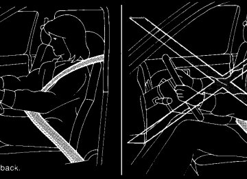
Shoulder belt height adjustment (For front and 2nd row seats) The shoulder belt anchor height should be ad- justed to the position best for you. (See (cid:147)Precau- tions on seat belt usage(cid:148) earlier in this section.) To adjust, push or pull outs1 the adjustment button and move the shoulder belt anchors2 to the desired position, so the belt passes over the center of the shoulder. The belt should be away from your face and neck, but not falling off your shoulder. Release the adjustment button to lock the shoulder belt anchor into position.
2nd row seats
WARNING
c After adjustment, release the adjust- ment button and try to move the shoul- der belt anchor up and down to make sure it is securely fixed in position.
c The shoulder belt anchor height should be adjusted to the position best for you. Failure to do so may reduce the effec- tiveness of the entire restraint system and increase the chance or severity of injury in an accident.
Safety(cid:151)Seats, seat belts and supplemental air bags 1-39
Z REVIEW COPY:—2004 Quest (van) Owners Manual (owners)—USA English (nna) 10/08/03—tbrooks X
SEAT BELT EXTENDERS If, because of body size or driving position, it is not possible to properly fit the lap-shoulder belt and fasten it, an extender is available which is compatible with the installed seat belts. The ex- tender adds approximately 8 inches (200 mm) of length and may be used for either the driver or front passenger seating position. See a NISSAN dealer for assistance if an extender is required.
WARNING
c Only NISSAN seat belt extenders, made by the same company which made the original equipment seat belts, should be used with NISSAN seat belts.
c Adults and children who can use the standard seat belt should not use an extender. Such unnecessary use could result in serious personal injury in the event of an accident.
c Never use seat belt extenders to install child restraints. If the child restraint is not secured properly, the child could be seriously injured in a collision or a sud- den stop.
SEAT BELT MAINTENANCE c To clean the seat belt webbing, apply a mild soap solution or any solution recom- mended for cleaning upholstery or carpet. Then wipe with a cloth and allow the seat belts to dry in the shade. Do not allow the seat belts to retract until they are completely dry.
c If dirt builds up in the shoulder belt guide of the seat belt anchors, the seat belts may retract slowly. Wipe the shoulder belt guide with a clean, dry cloth.
c Periodically check to see that the seat belt and the metal components, such as buckles, tongues, retractors, flexible wires and anchors, work properly. If loose parts, deterioration, cuts or other damage on the webbing is found, the entire seat belt as- sembly should be replaced.
1-40 Safety(cid:151)Seats, seat belts and supplemental air bags
CHILD RESTRAINTS
ARS1098
PRECAUTIONS ON CHILD RESTRAINTS
WARNING
c Infants and small children should al- ways be placed in an appropriate child restraint while riding in the vehicle. Failure to use a child restraint can re- sult in serious injury or death.
Z REVIEW COPY:—2004 Quest (van) Owners Manual (owners)—USA English (nna) 10/08/03—tbrooks X
WRS0256
WARNING
c Infants and small children should never be carried on your lap. It is not possible for even the strongest adult to resist the forces of a severe accident. The child could be crushed between the adult and parts of the vehicle. Also, do not put the same seat belt around both your child and yourself.
c Never install a rear-facing child re- straint in the front seat. An inflating supplemental front air bag could seri- ously injure or kill your child. A rear- facing child restraint must only be used in the rear seat.
c NISSAN recommends that the child re- straint be installed in the rear seat. Ac- cording to accident statistics, children are safer when properly restrained in the rear seat than in the front seat.
c An improperly installed child restraint could lead to serious injury or death in an accident.
In general, child restraints are designed to be installed with the lap portion of a three-point type seat belt. In addition, this vehicle is equipped with a universal child restraint lower anchor system, referred to as the LATCH (Lower Anchors and Tethers for CHildren) system. Some child re- straints include two rigid or webbing-mounted attachments that can be connected to these lower anchors. For details, see the (cid:147)LATCH (Lower Anchors and Tethers for CHildren) sys- tem(cid:148) later in this section. Child restraints for infants and small children of various sizes are offered by several manufactur- ers. When selecting any child restraint, keep the following points in mind:
c Choose only a restraint with a label certifying that it complies with Federal Motor Vehicle Safety Standard 213 or Canadian Motor Vehicle Safety Standard 213.
c Check the child restraint in your vehicle to be sure it is compatible with the vehicle(cid:146)s seat and seat belt system.
c If the child restraint is compatible with your vehicle, place your child in the child restraint and check the various adjustments to be sure the child restraint is compatible with your child. Always follow all recommended procedures.
All U.S. states and provinces of Canada require that infants and small children be restrained in an approved child restraint at all times while the vehicle is being oper- ated.
WARNING
c Improper use of a child restraint can increase the risk or severity of injury for both the child and other occupants of the vehicle.
Safety(cid:151)Seats, seat belts and supplemental air bags 1-41
Z REVIEW COPY:—2004 Quest (van) Owners Manual (owners)—USA English (nna) 10/08/03—tbrooks X
c Failure to use the retractor(cid:146)s locking mode will result in the child restraint not being properly secured. The re- straint could tip over or otherwise be unsecured and cause injury to the child in a sudden stop or collision.
c Follow all of the child restraint manu- facturer(cid:146)s instructions for installation and use. When purchasing a child re- straint, be sure to select one which will fit your child and vehicle. It may not be possible to properly install some types of child restraints in your vehicle.
c If the child restraint is not anchored properly, the risk of a child being in- jured in a collision or a sudden stop greatly increases.
c Adjustable seatbacks should be posi- tioned to fit the child restraint, but as upright as possible.
c After attaching the child restraint, test it before you place the child in it. Tilt it from side to side. Try to tug it forward and check to see if the belt holds the restraint in place. The child restraint should not move more than 1 inch. If the restraint is not secure, tighten the belt as necessary, or put the restraint in an- other seat and test it again.
c For a front-facing child restraint, check to make sure the shoulder belt does not go in front of the child(cid:146)s face or neck. If it does, put the shoulder belt behind the child restraint. If you must install a front facing child restraint in the front seat, see (cid:147)Installation on front passenger seat(cid:148) later in this section.
c When your child restraint is not in use, keep it secured with a seat belt to pre- vent it from being thrown around in case of a sudden stop or accident.
CAUTION
Remember that a child restraint left in a closed vehicle can become very hot. Check the seating surface and buckles before placing your child in the child restraint.
INSTALLATION ON 2ND ROW CAPTAIN(cid:146)S CHAIRS
WARNING
c The three-point seat belt in your vehicle is equipped with an automatic locking mode retractor which must be used when installing a child restraint.
1-42 Safety(cid:151)Seats, seat belts and supplemental air bags
Z REVIEW COPY:—2004 Quest (van) Owners Manual (owners)—USA English (nna) 10/08/03—tbrooks X
Front Facing (cid:151) step 1
Front Facing (cid:151) step 2
Front Facing (cid:151) step 3
WRS0297
WRS0298
WRS0299
Front facing When you install a child restraint on the 2nd row captain(cid:146)s chairs, follow these steps: 1. Position the child restraint on the seat. It can be placed in a front facing direction, de- pending on the size of the child. Remove the head restraint from the seat back. Store it in a secure place. Always follow the restraint manufacturer(cid:146)s instructions.
2. Route the seat belt tongue through the child restraint and insert it into the buckle until you hear and feel the latch engage. Be sure to follow the child restraint manu- facturer(cid:146)s instructions for belt routing.
3. Pull on the shoulder belt until all of the belt is fully extended. At this time, the seat belt retractor is in the automatic locking mode (child restraint mode). It reverts back to emergency locking mode when the seat belt is fully retracted.
Safety(cid:151)Seats, seat belts and supplemental air bags 1-43
Z REVIEW COPY:—2004 Quest (van) Owners Manual (owners)—USA English (nna) 10/08/03—tbrooks X
After the child restraint is removed and the seat belt is fully retracted, the automatic locking mode (child restraint mode) is canceled.
Front Facing (cid:151) step 4
Front Facing (cid:151) step 5
WRS0146
WRS0300
4. Allow the seat belt to retract. Pull up on the shoulder belt to remove any slack in the belt.
5. Before placing the child in the child restraint, use force to tilt the child restraint from side to side, and tug it forward to make sure that it is securely held in place. It should not move more than 1 inch (25 mm).
6. Check that the retractor is in the automatic locking mode by trying to pull more seat belt out of the retractor. If you cannot pull any more belt webbing out of the retractor, the retractor is in the automatic locking mode.
7. Check to make sure that the child restraint is properly secured prior to each use. If the belt is not locked, repeat steps 3 through 6.
1-44 Safety(cid:151)Seats, seat belts and supplemental air bags
Z REVIEW COPY:—2004 Quest (van) Owners Manual (owners)—USA English (nna) 10/08/03—tbrooks X
Rear Facing (cid:151) step 1
Rear Facing (cid:151) step 2
Rear Facing (cid:151) step 3
WRS0301
WRS0302
WRS0303
Rear facing When you install a child restraint on the 2nd row captain(cid:146)s chair, follow these steps: 1. Position the child restraint on the seat. The direction of the child restraint depends on the type of the child restraint and the size of the child. Always follow the restraint manu- facturer(cid:146)s instructions.
2. Route the seat belt tongue through the child restraint and insert it into the buckle until you hear and feel the latch engage. Be sure to follow the child restraint manu- facturer(cid:146)s instructions for belt routing.
3. Pull on the shoulder belt until all of the belt is fully extended. At this time, the seat belt retractor is in the automatic locking mode (child restraint mode). It reverts to emer- gency locking mode when the seat belt is fully retracted.
Safety(cid:151)Seats, seat belts and supplemental air bags 1-45
Z REVIEW COPY:—2004 Quest (van) Owners Manual (owners)—USA English (nna) 10/08/03—tbrooks X
7. Check to make sure that the child restraint is properly secured prior to each use. If the belt is not locked, repeat steps 3 through 6.
After the child restraint is removed and the seat belt fully retracted, the automatic locking mode (child restraint mode) is canceled. INSTALLATION ON 3RD ROW BENCH SEAT
WARNING
c The three-point seat belt in your vehicle is equipped with an automatic locking mode retractor which must be used when installing a child restraint.
c Failure to use the retractor(cid:146)s locking mode will result in the child restraint not being properly secured. The re- straint could tip over or otherwise be unsecured and cause injury to the child in a sudden stop or collision.
c When installing a child restraint system in the rear center position, both the center seat belt connector tongue and buckle tongue must be secured. See (cid:147)Attaching rear center seat belt(cid:148) earlier in this section.
Rear Facing (cid:151) step 4
Rear Facing (cid:151) step 5
WRS0304
WRS0305
4. Allow the seat belt to retract. Pull up on the shoulder belt to remove any slack in the belt.
5. Before placing the child in the child restraint, use force to tilt the child restraint from side to side, and tug it forward to make sure that it is securely held in place. It should not move more than 1 inch (25 mm).
6. Check that the retractor is in the automatic locking mode by trying to pull more seat belt out of the retractor. If you cannot pull any more seat belt webbing out of the retractor, the retractor is in the automatic locking mode.
1-46 Safety(cid:151)Seats, seat belts and supplemental air bags
Z REVIEW COPY:—2004 Quest (van) Owners Manual (owners)—USA English (nna) 10/08/03—tbrooks X
Front Facing (outboard) (cid:151) step 1
Front Facing (center) (cid:151) step 1
Front Facing (cid:151) step 2
WRS0325
LRS0313
WRS0250
Front facing
WARNING
Front facing child restraints can be in- stalled in all 3rd row bench seat positions. However, front facing child restraints that require the use of a top tether strap can be installed in the center 3rd row position only. Do not install a child restraint requir- ing a top tether strap in an outboard posi- tion and attempt to angle the tether to the 3rd row center anchor.
When you install a child restraint on the 3rd row bench seat, follow these steps: 1. Position the child restraint on the seat. It can be placed in a front facing direction, de- pending on the size of the child. Remove the head restraint from the seat back. Store it in a secure place. Always follow the restraint manufacturer(cid:146)s instructions.
2. Route the seat belt tongue through the child restraint and insert it into the buckle until you hear and feel the latch engage. Be sure to follow the child restraint manu- facturer(cid:146)s instructions for belt routing.
Safety(cid:151)Seats, seat belts and supplemental air bags 1-47
Z REVIEW COPY:—2004 Quest (van) Owners Manual (owners)—USA English (nna) 10/08/03—tbrooks X
Front Facing (cid:151) step 3
Front Facing (cid:151) step 4
Front Facing (cid:151) step 5
WRS0251
WRS0146
WRS0252
3. Pull on the shoulder belt until all of the belt is fully extended. At this time, the seat belt retractor is in the automatic locking mode (child restraint mode). It reverts back to emergency locking mode when the seat belt is fully retracted.
4. Allow the seat belt to retract. Pull up on the shoulder belt to remove any slack in the belt.
5. Before placing the child in the child restraint, use force to tilt the child restraint from side to side, and tug it forward to make sure that it is securely held in place. It should not move more than 1 inch (25mm).
6. Check that the retractor is in the automatic locking mode by trying to pull more seat belt out of the retractor. If you cannot pull any more belt webbing out of the retractor, the retractor is in the automatic locking mode.
7. Check to make sure that the child restraint is properly secured prior to each use. If the belt is not locked, repeat steps 3 through 6.
1-48 Safety(cid:151)Seats, seat belts and supplemental air bags
Z REVIEW COPY:—2004 Quest (van) Owners Manual (owners)—USA English (nna) 10/08/03—tbrooks X
After the child restraint is removed and the seat belt is fully retracted, the automatic locking mode (child restraint mode) is canceled.
Rear Facing (outboard) (cid:151) step 1
Rear Facing (center) (cid:151) step 1
WRS0323
LRS0312
Rear facing When you install a child restraint on the 3rd row bench seat, follow these steps: 1. Position the child restraint on the seat. The direction of the child restraint depends on the type of the child restraint and the size of the child. Always follow the restraint manu- facturer(cid:146)s instructions.
Safety(cid:151)Seats, seat belts and supplemental air bags 1-49
Z REVIEW COPY:—2004 Quest (van) Owners Manual (owners)—USA English (nna) 10/08/03—tbrooks X
Rear Facing (cid:151) step 2
Rear Facing (cid:151) step 3
Rear Facing (cid:151) step 4
WRS0309
WRS0324
WRS0253
2. Route the seat belt tongue through the child restraint and insert it into the buckle until you hear and feel the latch engage. Be sure to follow the child restraint manu- facturer(cid:146)s instructions for belt routing.
3. Pull on the shoulder belt until all of the belt is fully extended. At this time, the seat belt retractor is in the automatic locking mode (child restraint mode). It reverts to emer- gency locking mode when the seat belt is fully retracted.
4. Allow the seat belt to retract. Pull up on the shoulder belt to remove any slack in the belt.
1-50 Safety(cid:151)Seats, seat belts and supplemental air bags
Z REVIEW COPY:—2004 Quest (van) Owners Manual (owners)—USA English (nna) 10/08/03—tbrooks X
7. Check to make sure that the child restraint is properly secured prior to each use. If the belt is not locked, repeat steps 3 through 6.
After the child restraint is removed and the seat belt fully retracted, the automatic locking mode (child restraint mode) is canceled.
WRS0254
Rear Facing (cid:151) step 5
5. Before placing the child in the child restraint, use force to tilt the child restraint from side to side, and tug it forward to make sure that it is securely held in place. It should not move more than 1 inch (25mm).
6. Check that the retractor is in the automatic locking mode by trying to pull more seat belt out of the retractor. If you cannot pull any more seat belt webbing out of the retractor, the retractor is in the automatic locking mode.
WRS0295
LATCH anchor point label (2nd row cap-tain(cid:146)s chairs)
LATCH (Lower Anchors and Tethers for CHildren) SYSTEM
Safety(cid:151)Seats, seat belts and supplemental air bags 1-51
Z REVIEW COPY:—2004 Quest (van) Owners Manual (owners)—USA English (nna) 10/08/03—tbrooks X
restraint, refer to the illustration for the seating positions equipped with LATCH system anchors which can be used to secure the child restraint.
The LATCH system anchors are located at the rear of the seat cushion near the seatback. A label is attached to the seatback to help you locate the LATCH system anchors.
LATCH child restraints generally require the use of a top tether strap. See (cid:147)Top tether strap child restraint(cid:148) later in this section for installation in- structions.
When installing a child restraint, carefully read and follow the instructions in this manual and those supplied with the child restraint.
When you install a LATCH system compatible child restraint to the lower anchor attachments, follow these steps:
WARNING
Inspect the lower anchors by inserting your fingers into the lower anchor area and feeling to make sure there are no obstructions over the LATCH system an- chors, such as seat belt webbing or seat cushion material. The child restraint will not be secured properly if the LATCH sys- tem anchors are obstructed.
WRS0436
LATCH anchor point label (3rd row bench seat)WARNING
c Attach LATCH system compatible child restraints only at the locations shown. If a child restraint is not secured properly, your child could be seriously injured or killed in an accident.
c The LATCH system anchors are de- signed to withstand only those loads imposed by correctly fitted child re- straints. Under no circumstance are they to be used for adult seat belts or harnesses.
WRS0315
LATCH system anchor locations
Some child restraints include two rigid or webbing-mounted attachments that can be con- nected to two anchors located at certain seating positions in your vehicle. This system is known as the LATCH (Lower Anchors and Tethers for CHil- dren) system. This system may also be referred to as the ISOFIX or ISOFIX compatible system. With this system, you do not have to use a vehicle seat belt to secure the child restraint. Your vehicle is equipped with special anchor points that are used with LATCH system compatible child re- straints. Check your child restraint for a label stating that it is compatible with the LATCH sys- tem. This information may also be in the child restraint owner(cid:146)s manual. If you have such a child
1-52 Safety(cid:151)Seats, seat belts and supplemental air bags
Z REVIEW COPY:—2004 Quest (van) Owners Manual (owners)—USA English (nna) 10/08/03—tbrooks X
insert
1. To install the LATCH system compatible child restraint, the child restraint LATCH system anchor attachments into the anchor points on the seat. If the child re- straint is equipped with a top tether, see (cid:147)Top tether strap child restraint(cid:148) later in this section for installation instructions.
2. After attaching the child restraint and before placing the child in it, use force to tilt the child restraint from side to side and tug it forward to make sure that the child restraint is securely held in place. It should not move more than 1 inch.
3. Check to make sure that the child restraint is
properly secured prior to each use.
TOP TETHER STRAP CHILD RESTRAINT If your child restraint has a top tether strap, it must be secured to the anchor point provided behind its position.
WARNING
c Child restraint anchor points are de- signed to withstand only those loads imposed by correctly fitted child re- straints. Under no circumstances are they to be used for adult seat belts or harnesses.
c After removing a rear seat head re- straint for top tether installation, store it securely to prevent it from causing injury to passengers or damage to the vehicle in case of sudden braking or an accident. Always replace it and adjust properly when top tether is no longer in use.
First, secure the child restraint with the seat belt or the LATCH system (2nd row captain(cid:146)s chairs and the center position of the 3rd row bench seat only), as applicable.
For the front passenger seat in the 2 passenger cargo van only, adjust the head restraint to its highest position and route the top tether strap between the head restraint and the top of the seatback. Secure the tether strap to the tether anchor point on the floor directly behind the seat. Tighten the tether strap according to the manu- facturer(cid:146)s instructions to remove any slack.
For the 2nd and 3rd row seats, remove the head restraint from the seatback. Store it in a secure place. Position the top tether strap over the top of the seatback and secure it to the tether anchor bracket as shown later in this section. Tighten the tether strap according to the manufacturer(cid:146)s in- structions to remove any slack.
WARNING
A child restraint with a top tether strap can only be used in the 3rd row bench seat, center position. Do not place in an out- board seating position and attempt to angle the tether strap to the center position.
For best child restraint fit, see the child restraint installation instructions in this section and the child restraint manufacturer(cid:146)s instructions.
Safety(cid:151)Seats, seat belts and supplemental air bags 1-53
Z REVIEW COPY:—2004 Quest (van) Owners Manual (owners)—USA English (nna) 10/08/03—tbrooks X
LRS0322
WRS0210
LRS0307
Label
2nd row captain(cid:146)s chairs
Front passenger seat
(2 passenger cargo van only)
Anchor point locations Anchor points are located on the floor behind the front passenger seat (2 passenger cargo van only), on the back of the 2nd row captain(cid:146)s chairs and the back of the center seat position on the 3rd row bench seat as shown. If you have any questions when installing a top strap child restraint on the rear seat, consult your NISSAN dealer for details. The front passenger seat and 2nd row captain(cid:146)s chair anchor point locations are marked with the label shown. 1-54 Safety(cid:151)Seats, seat belts and supplemental air bags
Z REVIEW COPY:—2004 Quest (van) Owners Manual (owners)—USA English (nna) 10/08/03—tbrooks X
3rd row bench
1. Pull strap 2. Top tether anchor point
WRS0319
WRS0256
WRS0378
INSTALLATION ON FRONT PASSENGER SEAT
WARNING
c Never install a rear-facing child re- straint in the front passenger seat. Supplemental front air bags inflate with great force. A rear-facing child restraint could be struck by the supplemental front air bag in a crash and could seri- ously injure or kill your child.
c NISSAN recommends that child re- straints be installed in the rear seat. However, if you must install a forward- facing child restraint in the front pas- senger seat, move the passenger seat to the rearmost position. Also, be sure the front passenger air bag status light is illuminated to indicate the passenger air bag is OFF. See (cid:147)Front passenger air bag and status light(cid:148) earlier in this sec- tion for details.
Safety(cid:151)Seats, seat belts and supplemental air bags 1-55
Z REVIEW COPY:—2004 Quest (van) Owners Manual (owners)—USA English (nna) 10/08/03—tbrooks X
c A child restraint with a top tether strap should not be used in the front passen- ger seat unless the vehicle is the 2 pas- senger cargo van only.
c The three-point seat belt in your vehicle is equipped with an automatic locking mode retractor which must be used when installing a child restraint.
c Failure to use the retractor(cid:146)s locking mode will result in the child restraint not being properly secured. The re- straint could tip over or otherwise be unsecured and cause injury to the child in a sudden stop or collision.
WRS0379
WRS0159
Front Facing (cid:151) step 2
2. Route the seat belt tongue through the child restraint and insert it into the buckle until you hear and feel the latch engage. Be sure to follow the child restraint manu- facturer(cid:146)s instructions for belt routing.
Front Facing (cid:151) step 1
If you must install a child restraint in the front seat, follow these steps: 1. Position the child restraint on the front pas- senger seat. It should be placed in a front-facing direction only. Move the seat to the rearmost position. Adjust the head restraint to its highest position. Always follow the child restraint manufacturer(cid:146)s in- structions. Child restraints for infants must be used in the rear-facing direc- tion and therefore must not be used in the front seat.
1-56 Safety(cid:151)Seats, seat belts and supplemental air bags
Z REVIEW COPY:—2004 Quest (van) Owners Manual (owners)—USA English (nna) 10/08/03—tbrooks X
Front Facing (cid:151) step 3
Front Facing (cid:151) step 4
Front Facing (cid:151) step 5
WRS0160
WRS0161
WRS0380
3. Pull on the shoulder belt until all of the belt is fully extended. At this time, the seat belt retractor is in the automatic locking mode (child restraint mode). It reverts to emer- gency locking mode when the seat belt is fully retracted.
4. Allow the seat belt to retract slightly. Pull up on the shoulder belt to remove any slack in the belt.
5. Before placing the child in the child restraint, use force to tilt the child restraint from side to side, and tug it forward to make sure that it is securely held in place. It should not move more than 1 inch.
6. Check that the retractor is in the automatic locking mode by trying to pull more seat belt out of the retractor. If you cannot pull any more belt webbing out of the retractor, the retractor is in the automatic locking mode.
Safety(cid:151)Seats, seat belts and supplemental air bags 1-57
Z REVIEW COPY:—2004 Quest (van) Owners Manual (owners)—USA English (nna) 10/08/03—tbrooks X
7. Check to make sure the child restraint is properly secured prior to each use. If the seat belt locked, repeat steps 3
through 6.is not
8. Turn the ignition to the ON position. The passenger air bag status light should say (cid:147)PASS AIR BAG OFF(cid:148) If this light is not illuminated it may indicate a malfunction. Move the child restraint to another seating position. Have the sys- tem checked by a NISSAN dealer.
or
After the child restraint is removed and the seat belt is fully retracted, the automatic locking mode (child restraint mode) is canceled.
1-58 Safety(cid:151)Seats, seat belts and supplemental air bags
Z REVIEW COPY:—2004 Quest (van) Owners Manual (owners)—USA English (nna) 10/08/03—tbrooks X
MEMO
Safety(cid:151)Seats, seat belts and supplemental air bags 1-59
2 Instruments and controls
Instrument panel. . . . . . . . . . . . . . . . . . . . . . . . . . . . . . . . . . . 2-2
Meters and gauges . . . . . . . . . . . . . . . . . . . . . . . . . . . . . . . . 2-3
Speedometer and odometer . . . . . . . . . . . . . . . . . . . . . 2-4
Tachometer . . . . . . . . . . . . . . . . . . . . . . . . . . . . . . . . . . . . 2-4
Engine coolant temperature gauge . . . . . . . . . . . . . . . 2-4
Fuel gauge . . . . . . . . . . . . . . . . . . . . . . . . . . . . . . . . . . . . 2-5
Warning/indicator lights and audible reminders . . . . . . . 2-6
Checking bulbs . . . . . . . . . . . . . . . . . . . . . . . . . . . . . . . . 2-6
Warning lights . . . . . . . . . . . . . . . . . . . . . . . . . . . . . . . . . 2-6
Indicator lights . . . . . . . . . . . . . . . . . . . . . . . . . . . . . . . . . 2-9
Audible reminders . . . . . . . . . . . . . . . . . . . . . . . . . . . . . 2-12
Security system . . . . . . . . . . . . . . . . . . . . . . . . . . . . . . . . . . 2-12
Nissan vehicle immobilizer system (NVIS) . . . . . . . . 2-12
Windshield wiper and washer switch . . . . . . . . . . . . . . . 2-13
Switch operation . . . . . . . . . . . . . . . . . . . . . . . . . . . . . . 2-13
Rear window wiper and washer switch. . . . . . . . . . . . . . 2-14
Rear window and outside mirror (if so equipped) defroster switch . . . . . . . . . . . . . . . . . . . . . . . . . . . . . . . . . . 2-15
Headlight and turn signal switch. . . . . . . . . . . . . . . . . . . . 2-15
Headlight control switch. . . . . . . . . . . . . . . . . . . . . . . . 2-15
Daytime running light system (Canada only) . . . . . . 2-18
Instrument brightness control . . . . . . . . . . . . . . . . . . . 2-18
Turn signal switch . . . . . . . . . . . . . . . . . . . . . . . . . . . . . 2-19Fog light switch (if so equipped) . . . . . . . . . . . . . . . . 2-19
Cornering light . . . . . . . . . . . . . . . . . . . . . . . . . . . . . . . . 2-19
Hazard warning flasher switch . . . . . . . . . . . . . . . . . . . . . 2-20
Horn . . . . . . . . . . . . . . . . . . . . . . . . . . . . . . . . . . . . . . . . . . . .2-20
Heated seat (if so equipped). . . . . . . . . . . . . . . . . . . . . . . 2-21
Traction control system (TCS) off switch (if so equipped) . . . . . . . . . . . . . . . . . . . . . . . . . . . . . . . . . . 2-22
Vehicle dynamic control (VDC) off switch (if so equipped) . . . . . . . . . . . . . . . . . . . . . . . . . . . . . . . . . . 2-22
Rear sonar system off switch (if so equipped). . . . . . . . 2-22
Power outlet . . . . . . . . . . . . . . . . . . . . . . . . . . . . . . . . . . . . . 2-23
Storage . . . . . . . . . . . . . . . . . . . . . . . . . . . . . . . . . . . . . . . . .2-25
Note holder . . . . . . . . . . . . . . . . . . . . . . . . . . . . . . . . . . . 2-25
Upper instrument panel storage compartment. . . . . . . . . . . . . . . . . . . . . . . . . . . . . . . . . . 2-25
Lower instrument panel storage trays . . . . . . . . . . . . 2-26
Passenger seat storage tray (if so equipped) . . . . . 2-26
Center console. . . . . . . . . . . . . . . . . . . . . . . . . . . . . . . . 2-27
Glove box . . . . . . . . . . . . . . . . . . . . . . . . . . . . . . . . . . . . 2-28
Sunglasses holder . . . . . . . . . . . . . . . . . . . . . . . . . . . . . 2-28
Convenience hook. . . . . . . . . . . . . . . . . . . . . . . . . . . . . 2-29
Map pockets . . . . . . . . . . . . . . . . . . . . . . . . . . . . . . . . . . 2-29
Seatback pockets . . . . . . . . . . . . . . . . . . . . . . . . . . . . . 2-30Z REVIEW COPY:—2004 Quest (van) Owners Manual (owners)—USA English (nna) 10/08/03—tbrooks X
Grocery hooks . . . . . . . . . . . . . . . . . . . . . . . . . . . . . . . . 2-30
Umbrella holder . . . . . . . . . . . . . . . . . . . . . . . . . . . . . . . 2-30
Overhead console . . . . . . . . . . . . . . . . . . . . . . . . . . . . . 2-31
Cup holders . . . . . . . . . . . . . . . . . . . . . . . . . . . . . . . . . . 2-32
3rd row armrest bin . . . . . . . . . . . . . . . . . . . . . . . . . . . . 2-33
Cargo area storage bin. . . . . . . . . . . . . . . . . . . . . . . . . 2-34
Garment hook. . . . . . . . . . . . . . . . . . . . . . . . . . . . . . . . . 2-34
Head restraint storage . . . . . . . . . . . . . . . . . . . . . . . . . 2-34
Roof rack (if so equipped) . . . . . . . . . . . . . . . . . . . . . . 2-35
Windows . . . . . . . . . . . . . . . . . . . . . . . . . . . . . . . . . . . . . . . .2-36
Power windows . . . . . . . . . . . . . . . . . . . . . . . . . . . . . . . 2-36
Power vent windows (if so equipped) . . . . . . . . . . . . 2-38
Manual vent windows (if so equipped) . . . . . . . . . . . 2-38
Skyview(cid:153) roof (if so equipped) . . . . . . . . . . . . . . . . . . . . . 2-39
Sunroof (if so equipped). . . . . . . . . . . . . . . . . . . . . . . . . . . 2-39Automatic sunroof . . . . . . . . . . . . . . . . . . . . . . . . . . . . . 2-39
Lights on demand switch . . . . . . . . . . . . . . . . . . . . . . . . . . 2-41
Personal lights . . . . . . . . . . . . . . . . . . . . . . . . . . . . . . . . . . . 2-42
Map lights . . . . . . . . . . . . . . . . . . . . . . . . . . . . . . . . . . . . . . . 2-43
HomelinkT universal transceiver (if so equipped) . . . . . 2-43
Programming HomeLinkT. . . . . . . . . . . . . . . . . . . . . . . 2-44
Programming HomeLinkT for Canadian customers . . . . . . . . . . . . . . . . . . . . . . . . . . . . . . . . . . . . 2-45
Operating the HomeLinkT universal transceiver. . . . . . . . . . . . . . . . . . . . . . . . . . . . . . . . . . . . 2-45
Programming trouble-diagnosis . . . . . . . . . . . . . . . . . 2-45
Clearing the programmed information . . . . . . . . . . . . 2-46
Reprogramming a single HomeLinkT button . . . . . . 2-46
If your vehicle is stolen . . . . . . . . . . . . . . . . . . . . . . . . . 2-46Z REVIEW COPY:—2004 Quest (van) Owners Manual (owners)—USA English (nna) 10/08/03—tbrooks X
INSTRUMENT PANEL
1.
2.
3.
4.
5.
Driver side, center and passenger side ventilators (P. 4-17) Headlight and turn signal switch (P. 2-15) Steering wheel switch for audio control (if so equipped) (P. 4-41) Driver supplemental air bag/horn (P. 1-15, P. 2-20) Cruise control main/set switches (P. 5-12)
6. Windshield wiper/washer switch and
rear window wiper/washer switch (P. 2-13, 2-14)
7. Meters and gauges (P. 2-3) 8.
Display screen/Navigation system* (P. 4-2, P. 4-8)
9. Warning/indicator lights (P. 2-6) 10. Front passenger supplemental air bag
(P. 1-15)
11. Glove box (P. 2-28) 12. Climate controls (P. 4-17, 4-27) 13. Hazard warning flasher switch
(P. 2-20)
14. Audio system controls (P. 4-30) 15. Display screen/Navigation system*
controls (P. 4-2, 4-8)
2-2 Instruments and controls
WIC0599
16. Shift selector lever (P. 5-7)
Z REVIEW COPY:—2004 Quest (van) Owners Manual (owners)—USA English (nna) 10/08/03—tbrooks X
17. Tilt steering wheel control (P. 3-21) 18. Rear sonar system off switch (if so
equipped) (P. 2-22)
19. Vehicle dynamic control (VDC) off
switch (if so equipped) or Traction con- trol system (TCS) off switch (if so equipped) (P. 2-22, P. 2-22)
Instrument brightness control (P. 2-18)
20. Lights on demand switch (P. 2-41) 21. 22. Outside mirror controls (P. 3-24) *: Refer to the separate Navigation System Own- er(cid:146)s Manual (if so equipped). See the page number indicated in paren- theses for operating details.
METERS AND GAUGES
LIC0459
Tachometer
1. 2. Warning/indicator lights 3. 4. Odometer 5.
Speedometer
Engine coolant temperature gauge/Fuel gauge
Instruments and controls 2-3
Z REVIEW COPY:—2004 Quest (van) Owners Manual (owners)—USA English (nna) 10/08/03—tbrooks X
LIC0460
LIC0461
Speedometer
1. 2. Odometer SPEEDOMETER AND ODOMETER Speedometer The speedometer indicates vehicle speed in miles per hour (MPH) and kilometers per hour (km/h). Odometer The odometer records the total distance the ve- hicle has been driven.
TACHOMETER The tachometer indicates engine speed in revo- lutions per minute (r/min). Do not rev engine into the red zone s1 .
CAUTION
When engine speed approaches the red zone, shift to a higher gear. Operating the engine in the red zone may cause serious engine damage.
LIC0462
ENGINE COOLANT TEMPERATURE GAUGENOTE:
The ignition key must be in the ON position for the gauge to give a reading.
The gauge indicates the engine coolant tempera- ture. The engine coolant temperature is within the normal range s1 when the reading is within the zone shown in the illustration.
The engine coolant temperature varies with the outside air temperature and driving conditions.
2-4 Instruments and controls
Z REVIEW COPY:—2004 Quest (van) Owners Manual (owners)—USA English (nna) 10/08/03—tbrooks X
CAUTION
If the gauge indicates engine coolant tem- perature over the normal range, stop the vehicle as soon as safely possible. If the engine is overheated, continued opera- tion of the vehicle may seriously damage the engine. See (cid:147)If your vehicle over- heats(cid:148) in the (cid:147)In case of emergency(cid:148) sec- tion for immediate action required.
CAUTION
c If
the vehicle runs out of
fuel, the malfunction indicator lamp (MIL) may come on. Refuel as soon as possible. After a few driving trips, the lamp should turn off. If the lamp remains on after a few driving trips, have the vehicle inspected by a NISSAN dealer.
c For additional information, see (cid:147)Mal- function indicator lamp (MIL)(cid:148) later in this section.
LIC0463
FUEL GAUGE
NOTE:
The ignition key must be in the ON position for the gauge to give a reading. The gauge indicates the approximate fuel level in the tank. The low fuel warning light comes on when the amount of fuel in the tank is getting low. Refill the fuel tank before the gauge regis- ters E (Empty). The located on the driver(cid:146)s side of the vehicle.
indicates that the fuel filler lid is
Instruments and controls 2-5
Z REVIEW COPY:—2004 Quest (van) Owners Manual (owners)—USA English (nna) 10/08/03—tbrooks X
WARNING/INDICATOR LIGHTS AND AUDIBLE REMINDERS
or
or
Anti-lock brake warning light
Seat belt warning light and chime
or
Front passenger air bag status light
Brake warning light
Supplemental air bag warning light
Security indicator light (NVIS)
Charge warning light
Automatic transmission position indicator light
Slip indicator light
Door open warning light
Cruise main switch indicator light
Traction control system off indicator light (if so equipped)
Engine oil pressure warning light
Cruise set switch indicator light
Turn signal/hazard indicator lights
Low fuel warning light
High beam indicator light (Blue)
Vehicle dynamic control off indicator light (if so equipped)
Low tire pressure warning light
Malfunction indicator lamp (MIL)
Low windshield washer fluid warning light
Overdrive off indicator light
CHECKING BULBS With all doors closed, apply the parking brake and turn the ignition key to the ON position without starting the engine. The following lights will come on:
or
The following lights come on briefly and then go off:
or
If any light fails to come on, it may indicate a burned-out bulb or an open circuit in the electrical system. Have the system repaired promptly.
2-6 Instruments and controls
WARNING LIGHTS
or
Anti-lock brake warning light
If the light comes on while the engine is running, it may indicate the anti-lock brake system is not functioning properly. Have the system checked by a NISSAN dealer.
Z REVIEW COPY:—2004 Quest (van) Owners Manual (owners)—USA English (nna) 10/08/03—tbrooks X
Turn off the engine, and start it again by slowly turning the ignition key (quickly do- ing so may cause the ABS light to stay on when there is nothing wrong). If the light stays on, have the system checked by a NISSAN dealer.
If an abnormality occurs in the system, the anti- lock function ceases, but the regular braking system continues to operate. If the light comes on while you are driving, contact a NISSAN dealer for repair.
or
Brake warning light
This light functions for both the parking brake and the foot brake systems.
When the ignition key is in the ON position, the light comes on when the parking brake is applied, and also warns of a low brake fluid level. If the light comes on while the engine is running with the parking brake not applied, stop the vehicle and perform the following:
1. Check the brake fluid level. Add brake fluid as necessary. See (cid:147)Brake fluid(cid:148) in the (cid:147)Main- tenance and do-it-yourself(cid:148) section of this manual.
2.
If the brake fluid level is correct, have the brake system checked by a NISSAN dealer.
WARNING
c Your vehicle is equipped with an auto- matic engine cooling fan. It may come on at any time without warning, even if the ignition key is in the OFF position and the engine is not running. To avoid injury, always disconnect the negative battery cable before working near the fan.
c Pressing the brake pedal with the en- gine stopped and/or a low brake fluid level may increase your stopping dis- tance and braking will require greater pedal effort as well as pedal travel.
c If the brake fluid level
is below the MINIMUM or MIN mark on the brake fluid reservoir, do not drive until the brake system has been checked at a NISSAN dealer.
Charge warning light
If this light comes on while the engine is running, it may indicate the charging system is not func- tioning properly. Turn the engine off and check
the generator belt. If the belt is loose, broken, missing, or if the light remains on, see a NISSAN dealer immediately.
CAUTION
Do not continue driving if the generator belt is loose, broken or missing.
Door open warning light
This light comes on when any of the doors are not closed securely while the ignition key is in the ON position.
Engine oil pressure warning light
This light warns of low engine oil pressure. If the light flickers or comes on during normal driving, pull off the road in a safe area, stop the engine immediately and call a NISSAN dealer or other authorized repair shop. The engine oil pressure warning light is not designed to indicate a low oil level. Use the dipstick to check the oil level. See (cid:147)Engine oil(cid:148) in the (cid:147)Maintenance and do-it-yourself(cid:148) section of this manual.
Instruments and controls 2-7
Z REVIEW COPY:—2004 Quest (van) Owners Manual (owners)—USA English (nna) 10/08/03—tbrooks X
CAUTION
Running the engine with the engine oil pressure warning light on could cause se- rious damage to the engine almost imme- diately. Such damage is not covered by warranty. Turn off the engine as soon as it is safe to do so.
Low fuel warning light
This light comes on when the fuel level in the fuel tank is getting low. Refuel as soon as it is conve- nient, preferably before the fuel gauge reaches E (Empty). There will be a small reserve of fuel in the tank when the fuel gauge needle reaches E (Empty).
Low tire pressure warning light
This light warns of low tire pressure.
NISSAN(cid:146)s low tire pressure warning system is a tire pressure monitoring system. It monitors tire pressure of all tires except the spare. When the tire pressure monitoring system warning light is lit, one or more of your tires is significantly under- inflated. You should stop and check your tires as soon as possible, and inflate them to the proper pressure as indicated on the vehicle(cid:146)s tire infor- mation placard. Driving on a significantly under- 2-8 Instruments and controls
inflated tire causes the tire to overheat and can lead to tire failure. Under-inflation also reduces fuel efficiency and tire tread life, and may affect the vehicle(cid:146)s handling and stopping ability. Each tire, including the spare, should be checked monthly when cold and set to the recommended inflation pressure as specified in the vehicle plac- ard and owner(cid:146)s manual.
The recommended inflation pressure may also be found on the Tire and Loading Information Label. Low tire pressure warning:
If the vehicle is being driven with very low tire pressure (lower than 28 psi, 193 kPa), the light will illuminate and the chime will sound for about 10 seconds.
For additional information, see (cid:147)Low tire pressure warning system(cid:148) in the (cid:147)Starting and driving(cid:148) section and (cid:147)Low tire pressure warning system(cid:148) in the (cid:147)In case of emergency(cid:148) section.
WARNING
c If the light does not come on with the key switch turned ON, have the vehicle checked by a NISSAN dealer as soon as possible.
c If the light comes on while driving, avoid sudden steering maneuvers or abrupt braking, reduce vehicle speed, pull off the road to a safe location and stop the vehicle as soon as possible. Serious vehicle damage could occur and may lead to an accident and could result in serious personal injury. Check the tire pressure for all four tires. Adjust the tire pressure to the recommended COLD tire pressure shown on the Tire and Loading Information label to turn the low tire pressure warning light OFF. If the light still comes on while driving after adjusting the tire pressure, a tire may be flat. If you have a flat tire, re- place it with a spare tire as soon as possible.
c When a spare tire is mounted or a wheel is replaced, tire pressure will not be indicated and the low tire pressure warning system will not function. Con- tact your NISSAN dealer as soon as possible for tire replacement and/or system resetting.
Z REVIEW COPY:—2004 Quest (van) Owners Manual (owners)—USA English (nna) 10/08/03—tbrooks X
CAUTION
c The low tire pressure warning system is not a substitute for the regular tire pres- sure check. Be sure to check the tire pressure regularly.
c If the vehicle is being driven at speeds of less than 20 MPH (32 km/h), the low tire pressure warning system may not operate correctly.
c Be sure to install the specified size of
tires to the 4 wheels correctly.
Low windshield washer fluid warning light
This light comes on when the windshield washer fluid is at a low level. Add windshield washer fluid as necessary. See the (cid:147)Maintenance and do-it- yourself(cid:148) section of this manual.
Seat belt warning light and chime
The light and chime remind you to fasten your seat belts. The light illuminates whenever the ignition key is turned to the ON or START position and remains illuminated until the driver(cid:146)s seat belt is fastened. At the same time, the chime sounds for about 7 seconds unless the driver(cid:146)s seat belt is securely fastened.
Refer to (cid:147)Seat belts(cid:148) in the (cid:147)Safety(cid:151)Seats, seat belts and supplemental air bags(cid:148) section for pre- cautions on seat belt usage.
Supplemental air bag warning light
the following conditions occur,
When the ignition key is in the ON or START position, the supplemental air bag warning light illuminates for about 7 seconds and then turns off. This means the system is operational. If any of the supplemental front air bag, supplemental side air bag (if so equipped), curtain side-impact air bags, and pre-tensioner seat belt systems need servicing and your vehicle must be taken to a NISSAN dealer: c The supplemental air bag warning light re-
mains on after approximately 7 seconds.
c The supplemental air bag warning light
flashes intermittently.
c The supplemental air bag warning light does
not come on at all.
Unless checked and repaired, the supplemental restraint system (air bag system) and/or the pre- tensioner seat belts may not function properly. For additional details see (cid:147)Supplemental restraint system(cid:148) in the (cid:147)Safety(cid:151)Seats, seat belts and supplemental air bags(cid:148) section of this manual.
WARNING
If the supplemental air bag warning light is on, it could mean that the supplemental front air bag, supplemental side air bag, curtain side-impact air bag systems (if so equipped) and/or pre-tensioner seat belt systems will not operate in an accident.
INDICATOR LIGHTS
Automatic transmission posi- tion indicator light
When the ignition key is turned to the ON posi- tion, the indicator in the tachometer shows the automatic transmission selector lever position. See (cid:147)Driving the vehicle(cid:148) in the (cid:147)Starting and driving(cid:148) section of this manual.
Cruise main switch indicator light
The light comes on when the cruise control main switch is pushed. The light goes out when the main switch is pushed again. When the cruise main switch indicator light comes on, the cruise control system is operational.
Instruments and controls 2-9
Z REVIEW COPY:—2004 Quest (van) Owners Manual (owners)—USA English (nna) 10/08/03—tbrooks X
Cruise set switch indicator light
The light comes on while the vehicle speed is controlled by the cruise control system. If the light blinks while the engine is running, it may indicate the cruise control system is not functioning prop- erly. Have the system checked by a NISSAN dealer.
High beam indicator light (Blue)
This blue light comes on when the headlight high beams are on and goes out when the low beams are selected. The high beam indicator light also comes on when the passing signal is activated.
Malfunction indicator lamp (MIL)
If this indicator lamp comes on steady or blinks while the engine is running, it may indicate a potential emission control malfunction. The malfunction indicator lamp may also come on steady if the fuel filler cap is loose or missing, or if the vehicle runs out of fuel. Check to make sure the fuel filler cap is installed and closed tightly, and that the vehicle has at least 3 gallons of fuel in the fuel tank. 2-10 Instruments and controls
lamp should After a few driving trips, the turn off if no other potential emission control system malfunction exists. Operation
The malfunction indicator lamp will come on in one of two ways: c Malfunction indicator lamp on steady (cid:151) An emission control system malfunction has been detected. Check the fuel filler cap. If the fuel filler cap is loose or missing, tighten or install the cap and continue to drive the vehicle. The lamp should turn off after a few driving trips. If the lamp does not turn off after a few driving trips, have the vehicle inspected by a NISSAN dealer. You do not need to have your vehicle towed to the dealer.
c Malfunction indicator lamp blinking (cid:151) An engine misfire has been detected which may damage the emission control system. To re- duce or avoid emission control system dam- age:
(cid:150) do not drive at speeds above 45 MPH
(72 km/h).
(cid:150) avoid hard acceleration or deceleration.
(cid:150) avoid steep uphill grades.
(cid:150) if possible, reduce the amount of cargo
being hauled or towed.
The malfunction indicator lamp may stop blinking and come on steady. Have the vehicle inspected by a NISSAN dealer. You do not need to have your vehicle towed to the dealer.
CAUTION
Continued vehicle operation without hav- ing the emission control system checked and repaired as necessary could lead to poor driveability, reduced fuel economy, and possible damage to the emission con- trol system.
Overdrive off indicator light
This light comes on when the overdrive function is OFF. The automatic transmission overdrive function is controlled by the overdrive switch. See (cid:147)Driving the vehicle(cid:148) in the (cid:147)Starting and driving(cid:148) section of this manual.
or
Front passenger air bag status light
The front passenger air bag status light ( or ) will be lit and the passenger front air bag will be OFF depending on how the front passenger seat is being used.
Z REVIEW COPY:—2004 Quest (van) Owners Manual (owners)—USA English (nna) 10/08/03—tbrooks X
For front passenger air bag status light operation, see (cid:147)Front passenger air bag and status light(cid:148) in the (cid:147)Safety (cid:151) Seats, seat belts and supplemental air bags(cid:148) section of this manual.
The system operates in all transmission shift lever positions, but the system can upshift the trans- mission only as high as the indicated shift lever position.
Security indicator light (NVIS)
This light blinks whenever the ignition switch is in the LOCK, OFF or ACC position. This function indicates the security system equipped on the vehicle is operational.
For additional information, see (cid:147)Security system(cid:148) later in this section.
Slip indicator light
This indicator light will blink when the traction control system is limiting wheel spin. Slippery road conditions may exist if the slip indicator blinks on. If this happens, adjust your driving accordingly.
The slip indicator light also comes on when you turn the ignition key to the ON position. The light will turn off after about 2 seconds if the system is operational. If the light does not come on or go off, have the traction control system checked by a NISSAN dealer.
Traction control system off indicator light (if so equipped) This indicator light comes on when the traction control off switch is pushed to OFF. This indi- cates the traction control system is not operating.
Push the traction control off switch again or re- start the engine and the system will operate nor- mally. See (cid:147)Traction control system (TCS)(cid:148) in the (cid:147)Starting and driving(cid:148) section of this manual.
The traction control light also comes on when you turn the ignition key to the ON position. The light will turn off after about 2 seconds if the traction control system (TCS) is operational. If the light stays on or comes on along with the SLIP indica- tor light while you are driving, have the traction control system checked by a NISSAN dealer.
While the traction control system is operating, you might feel slight vibration or hear the system working when starting the vehicle or accelerat- ing, but this is normal.
Turn signal/hazard indicator lights
The appropriate light flashes when the turn signal switch is activated. Both lights flash when the hazard switch is turned on.
Vehicle dynamic control off indicator light (if so equipped) This indicator light comes on when the vehicle dynamic control off switch is pushed to OFF. This indicates the vehicle dynamic control system is not operating. Push the vehicle dynamic control off switch again or restart the engine and the system will operate normally. See (cid:147)Vehicle dynamic control (VDC) system(cid:148) in the (cid:147)Starting and driving(cid:148) section of this manual. The vehicle dynamic control light also comes on when you turn the ignition key to the ON position. The light will turn off after about 2 seconds if the system is operational. If the light stays on or comes on along with the SLIP indicator light while you are driving, have the vehicle dynamic control system checked by a NISSAN dealer.
Instruments and controls 2-11
Z REVIEW COPY:—2004 Quest (van) Owners Manual (owners)—USA English (nna) 10/08/03—tbrooks X
SECURITY SYSTEM
NISSAN VEHICLE IMMOBILIZER SYSTEM (NVIS) The NISSAN Vehicle Immobilizer System (NVIS) will not allow the engine to start without the use of a registered NVIS key. If the engine fails to start using a registered NVIS key (for example, when interference is caused by another NVIS key, an automated toll road device or automatic payment device on the key ring), restart the engine using the following proce- dures: 1. Leave the ignition switch in the ON position
for approximately 5 seconds.
2. Turn the ignition switch to the OFF or LOCK position, and wait approximately 5 seconds.
3. Repeat steps 1 and 2. 4. Restart the engine while holding the device (which may have caused the interference) separate from the registered NVIS key.
If the no start condition re-occurs, NISSAN rec- ommends placing the registered NVIS key on a separate key ring to avoid interference from other devices.
While the vehicle dynamic control system is op- erating, you might feel slight vibration or hear the system working when starting the vehicle or ac- celerating, but this is normal. AUDIBLE REMINDERS Brake pad wear warning The front disc brake pads have audible wear warnings. When a front brake pad requires re- placement, it makes a high pitched scraping sound when the vehicle is in motion, whether or not the brake pedal is depressed. Have the brakes checked as soon as possible if the warn- ing sound is heard. Key reminder chime A chime sounds if the driver(cid:146)s door is opened while the key is left in the ignition switch. Remove the key and take it with you when leaving the vehicle. Light reminder chime With the ignition switch in the OFF position, a chime sounds when the driver(cid:146)s door is opened if the headlights or parking lights are on. Turn the headlight control switch off before leav- ing the vehicle.
2-12 Instruments and controls
Statement related to Section 15 of FCC Rules for NISSAN Vehicle Immobilizer Sys- tem (CONT ASSY (cid:151) IMMOBILIZER, ANT ASSY (cid:151) IMMOBILIZER) This device complies with part 15 of the FCC Rules and RSS-210 of Industry Canada. Operation is subject to the follow- ing two conditions; (1) This device may not cause harmful in- terference, and (2) this device must accept any interference received, including inter- ference that may cause undesired opera- tion of the device. CHANGES OR MODIFICATIONS NOT EX- PRESSLY APPROVED BY THE MANUFAC- TURER FOR COMPLIANCE COULD VOID THE USER(cid:146)S AUTHORITY TO OPERATE THE EQUIPMENT.
Z REVIEW COPY:—2004 Quest (van) Owners Manual (owners)—USA English (nna) 10/08/03—tbrooks X
WINDSHIELD WIPER AND WASHER SWITCH
LIC0474
LIC0386
Security indicator light The security indicator light blinks whenever the ignition switch is in the LOCK, OFF or ACC position. This function indicates the NISSAN Ve- hicle Immobilizer System (NVIS) is operational. If the NVIS is malfunctioning, the light will remain on while the ignition key is in the ON position. If the light still remains on and/or the en- gine will not start, see a NISSAN dealer for NVIS service as soon as possible. Please bring all NVIS keys that you have when visiting your NISSAN dealer for service.
SWITCH OPERATION The windshield wiper and washer operates when the ignition switch is in the ON position.
Push the lever down to operate the wiper at the following speed: s1
Intermittent (cid:151) intermittent operation can be adjusted by turning the knob toward sA (Slower) or sB (Faster). Also, the intermit- tent operation speed varies in accordance with the vehicle speed. (For example, when the vehicle speed is high, the intermittent operation speed will be faster.)
NOTE:
You can turn on or turn off the driving speed dependent intermittent wiper func- tion. Refer to (cid:147)Personalized settings menu(cid:148) (vehicles without navigation sys- tem) or (cid:147)Vehicle electronic systems(cid:148) (ve- hicles with navigation system) in the (cid:147)Dis- play screen, heater, air conditioner and audio systems(cid:148) section later in this manual. s2
Low (cid:151) continuous low speed operation s3 High (cid:151) continuous high speed operation Push the lever up s4 to have one sweep opera- tion of the wiper. Pull the lever toward you s5
to operate the washer. The wiper will also operate several times.WARNING
In freezing temperatures the washer solu- tion may freeze on the windshield and obscure your vision which may lead to an accident. Warm the windshield with the defroster before you wash the windshield.
CAUTION
c Do not operate the washer continu-
ously for more than 30 seconds.
Instruments and controls 2-13
Z REVIEW COPY:—2004 Quest (van) Owners Manual (owners)—USA English (nna) 10/08/03—tbrooks X
REAR WINDOW WIPER AND WASHER SWITCH
LIC0468
The rear window wiper and washer operate when the ignition switch is in the ON position.Turn the switch clockwise from the OFF position to operate the wiper. s1
Intermittent (cid:150) intermittent operation (not ad- justable)
Low (cid:150) continuous low speed operation
s2
Push the switch forward s3
to operate the washer. The wiper will also operate several times.WARNING
In freezing temperatures the washer solu- tion may freeze on the window and ob- scure your vision. Warm the rear window with the defroster before you wash the rear window.
CAUTION
c Do not operate the washer continu-
ously for more than 30 seconds.
c Do not operate the washer if the reser-
voir tank is empty.
c Do not fill the window washer reservoir tank with washer fluid concentrates at full strength. Some methyl alcohol based washer fluid concentrates may permanently stain the grille if spilled while filling the window washer reser- voir tank.
c Pre-mix washer fluid concentrates with water to the manufacturer(cid:146)s recom- mended levels before pouring the fluid into the window washer reservoir tank. Do not use the window washer reservoir tank to mix the washer fluid concen- trate and water.
2-14 Instruments and controls
Z REVIEW COPY:—2004 Quest (van) Owners Manual (owners)—USA English (nna) 10/08/03—tbrooks X
REAR WINDOW AND OUTSIDE MIRROR (if so equipped) DEFROSTER SWITCH
HEADLIGHT AND TURN SIGNAL SWITCH
LIC0487
LIC0488
LIC0560
Type A
To defrost the rear window glass and outside mirrors (if so equipped), start the engine and turn the rear window defroster switch clockwise (Type A), or push the rear window defroster switch on (Type B). The rear window defroster indicator light on the display screen comes on. Turn (Type A) or push (Type B) the switch again to turn the defroster off.
The rear window defroster automatically turns off after approximately 15 minutes.
Type B
CAUTION
When cleaning the inner side of the rear window, be careful not to scratch or dam- age the rear window defroster.
Type A
HEADLIGHT CONTROL SWITCH Lighting s1 When turning the switch to the
posi- tion, the front parking, tail, license plate and instrument panel lights come on. s2 When turning the switch to the
posi- tion, the headlights come on and all the other lights remain on.
Instruments and controls 2-15
Z REVIEW COPY:—2004 Quest (van) Owners Manual (owners)—USA English (nna) 10/08/03—tbrooks X
LIC0687
LIC0688
LIC0515
Type B
Type C
2-16 Instruments and controls
Autolight system (if so equipped) The autolight sensor s1 is located on top of the instrument panel. The autolight system allows the headlights to be set so they turn on and off automatically. The autolight system can: c Turn on the headlights, front parking, tail, license plate and instrument panel lights au- tomatically when it is dark.
c Turn off all the lights when it is light. c Keep all the lights on for up to 180 seconds after you turn the key to OFF and all doors are closed.
Z REVIEW COPY:—2004 Quest (van) Owners Manual (owners)—USA English (nna) 10/08/03—tbrooks X
NOTE: Autolight activation sensitivity and the time delay for autolight shutoff can be ad- justed. See (cid:147)Personalized settings menu(cid:148) (vehicles without navigation system) or (cid:147)Vehicle electronic systems(cid:148) (vehicles with navigation system) in the (cid:147)Display screen, heater, air conditioner and audio systems(cid:148) section later in this manual. To turn on the autolight system: 1. Make sure the headlight switch is in the
AUTO position.
2. Turn the ignition key to ON. 3. The autolight system automatically turns the
headlights on and off.
Initially, if the ignition switch is turned OFF and a door is opened and left open, the headlights remain on for 5 minutes. During that 5 minutes: c if all doors are closed, the headlights remain
on for 45 seconds, then turn off.
c if another door is opened, then the 5 minute
timer is reset.
To turn the autolight system off, turn the switch to the OFF,
position.
, or
Be sure you do not put anything on top of the autolight sensor located on top of the instrument panel. The autolight sensor controls the autolight; if it is covered, the autolight sensor reacts as if it is dark out and the headlights will illuminate. If this occurs while parked with the engine off and the key in the ON position, your vehi- cle(cid:146)s battery could become discharged.
LIC0390
Headlight beam select s1 To select the high beam function, push the lever forward. The high beam lights come on and the
light illuminates.
s2 Pull the lever back to select the low beam. s3 Pulling and releasing the lever flashes the
headlight high beams on and off.
Battery saver system If the ignition switch is turned OFF while the headlight switch is in the posi- tion, the headlights will turn off after 5 minutes.
or
Instruments and controls 2-17
Z REVIEW COPY:—2004 Quest (van) Owners Manual (owners)—USA English (nna) 10/08/03—tbrooks X
After the headlights automatically turn off with the headlight switch in the position, the headlights will illuminate again for 5 minutes if the headlight switch is moved to the OFF position and then turned to the position.
or
or
CAUTION
c Be sure to turn the light switch to the OFF position when you leave the ve- hicle for extended periods of time, oth- erwise the battery will go dead.
c Never leave the light switch on when the engine is not running for extended periods of time even if the headlights turn off automatically.
DAYTIME RUNNING LIGHT SYSTEM (Canada only) The headlights automatically illuminate at a re- duced intensity when the engine is started with the parking brake released. The daytime running lights operate with the headlight switch in the OFF position or in the position. Turn the headlight switch to the position for full illumination when driving at night.
If the parking brake is applied before the engine is started, the daytime running lights do not illumi- nate. The daytime running lights illuminate when
2-18 Instruments and controls
the parking brake is released. The daytime run- ning lights will remain on until the ignition switch is turned off.
WARNING
When the daytime running light system is active, tail lights on your vehicle are not on. It is necessary at dusk to turn on your headlights. Failure to do so could cause an accident injuring yourself and others.
LIC0392
INSTRUMENT BRIGHTNESS CONTROL The instrument cluster illuminates when the igni- tion switch is in ON position. The instrument brightness control operates when the the AUTO, Turn the control to adjust the brightness of instru- ment panel lights when driving at night.