- 2005 Nissan Murano Owners Manuals
- Nissan Murano Owners Manuals
- 2007 Nissan Murano Owners Manuals
- Nissan Murano Owners Manuals
- 2012 Nissan Murano Owners Manuals
- Nissan Murano Owners Manuals
- 2009 Nissan Murano Owners Manuals
- Nissan Murano Owners Manuals
- 2004 Nissan Murano Owners Manuals
- Nissan Murano Owners Manuals
- 2011 Nissan Murano Owners Manuals
- Nissan Murano Owners Manuals
- 2003 Nissan Murano Owners Manuals
- Nissan Murano Owners Manuals
- 2010 Nissan Murano Owners Manuals
- Nissan Murano Owners Manuals
- 2006 Nissan Murano Owners Manuals
- Nissan Murano Owners Manuals
- Download PDF Manual
-
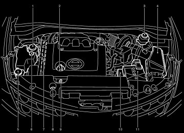
HOOD
equipment and the receiver
— Connect the equipment into an outlet on a circuit different from that to which the receiver is connected.
— Consult the dealer or an experienced
radio/TV technician for help.
1. Pull the hood lock release handle 쎻1 located below the instrument panel; the hood will then spring up slightly.
2. Move the lever 쎻2 at the front of the hood
with your fingertips and raise the hood.
3. When closing the hood, slowly close the
hood and make sure it locks into place.
SPA1578
WARNING
쐌 Make sure the hood is completely closed and latched before driving. Failure to do so could cause the hood to fly open and result in an accident. 쐌 If you see steam or smoke coming to
from the engine compartment, avoid injury do not open the hood.
3-24 Pre-driving checks and adjustments
墌 05.4.8/Z50-D/V5.0 墍
BACK DOOR
in the “5. Starting and driving” section for exhaust gas.
SPA1947
쐌 The power door lock system allows you to lock or unlock all doors including the back door simultaneously.쐌 Push the opener and pull up the back door to
open.
WARNING
Do not drive with the back door open. This could allow dangerous exhaust gases to be drawn into the vehicle. See “Precautions when starting and driving”
SPA1915
Emergency unlock lever If the back door cannot be opened with the door lock switch or remote controller due to a dis- charged battery, follow the next steps. 1. Remove the cover inside of the back door
with a suitable tool.
2. Move the lever toward the direction 쎻A as
illustrated to open the back door.
Contact a NISSAN dealer as soon as possible.
Pre-driving checks and adjustments 3-25
墌 05.4.8/Z50-D/V5.0 墍
FUEL FILLER LID
WARNING
쐌 Always be sure the back door has been closed securely to prevent it from opening while driving.
쐌 Do not drive with the back door open. This could allow dangerous exhaust gases to be drawn into the vehicle.
switch once model).
(Intelligent Key
equipped
쐌 Push the passenger side door handle request switch or back door request switch twice (Intelligent Key equipped model).
To lock, close the fuel filler lid and lock the doors.
SPA1580
OPEN THE FILLER LID To open the fuel filler lid, unlock it using one of the following operations, then push the right- hand side of the lid 쎻A . 쐌 Push the unlock button on the remote keyless
entry once.
쐌 Insert the key into the door lock cylinder and
turn the door key clockwise twice.
쐌 Push the power door lock switch to the
unlock side.
쐌 Push the driver’s side door handle request
3-26 Pre-driving checks and adjustments
墌 05.4.8/Z50-D/V5.0 墍
FUEL FILLER CAP The fuel filler cap is a ratcheting type. Turn the cap counterclockwise 쎻A to remove. To tighten, turn the cap clockwise until ratchet- ing clicks are heard. Put the fuel filler cap on the cap holder 쎻B while refueling.
WARNING
쐌 Gasoline is extremely flammable and
SPA1581A
highly explosive under certain condi- tions. You could be burned or seri- ously injured if it is misused or mis- handled. Always stop the engine and do not smoke or allow open flames or sparks near the vehicle when refu- eling.
쐌 Fuel may be under pressure. Turn the cap a third of a turn, and wait for any “hissing sound” to stop to prevent fuel from spraying out and possibly causing personal injury. Then remove the cap.
쐌 Do not attempt to top off the fuel tank after the fuel pump nozzle shuts off automatically. Continued refueling may cause fuel overflow, resulting in fuel spray and possibly a fire.
쐌 Use only an original equipment type fuel filler cap as a replacement. It has a built-in safety valve needed for proper operation of the fuel system and emission control system. An in- correct cap can result in a serious It malfunction and possible injury. could also cause the malfunc- tion indicator lamp to come on.
쐌 Do not fill a portable fuel container in the vehicle or trailer. Static electricity can cause an explosion of flammable liquid, vapor or gas in any vehicle or trailer. To reduce the risk of serious injury or death when filling portable fuel containers: — Always place the container on the
ground when filling.
— Do not use electronic devices
Pre-driving checks and adjustments 3-27
墌 05.4.8/Z50-D/V5.0 墍
when filling.
— Keep the pump nozzle in contact with the container while you are filling it.
— Use only approved portable fuel
containers for flammable liquid.
쐌 Never pour fuel into the throttle body
to attempt to start your vehicle.
CAUTION
쐌 If fuel is spilled on the vehicle body, flush it away with water to avoid paint damage.
쐌 Tighten until the fuel filler cap clicks. Failure to tighten the fuel filler cap mal- properly may cause the function indicator lamp (MIL) to illu- lamp illuminates minate. If the because the fuel filler cap is loose or missing, tighten or install the cap and continue to drive the vehicle. The lamp should turn off after a few lamp does
driving trips. If the
3-28 Pre-driving checks and adjustments
STEERING WHEEL
not turn off after a few driving trips, have the vehicle inspected by a NISSAN dealer.
쐌 For additional information, see the “Malfunction indicator lamp (MIL)” in the “Instruments and controls” sec- tion.
SPA1582
TILT OPERATION The steering wheel will pop up when the lock lever is pulled as illustrated 쎻1 . Keep holding the lock lever and adjust steering wheel to the desired position 쎻2 . Release the lock lever to lock the steering wheel.
the
WARNING
쐌 Do not adjust the steering wheel while driving. You could lose control
墌 05.4.8/Z50-D/V5.0 墍
PEDAL POSITION ADJUSTMENT (if so equipped)
of your vehicle and cause an acci- dent.
쐌 Do not put anything on or near the
steering wheel when tilting.
CAUTION
Do not adjust the pedal position with your foot on the pedal.
SPA1574
The accelerator and brake pedals can be ad- justed for driving comfort. Use the pedal adjusting switch to adjust the brake and accelerator pedal position forward 쎻1
or backward 쎻2 . Pedal adjustment can only be performed when: 쐌 Ignition switch is in the OFF or ACC position,or
쐌 Ignition switch is ON and the shift lever is in
the P (Park) position
The brake and accelerator pedals cannot be adjusted separately.
Pre-driving checks and adjustments 3-29
墌 05.4.8/Z50-D/V5.0 墍
SUN VISORS
MIRRORS
CAUTION
쐌 Do not store the main sun visor be- fore storing the extension sun visor. 쐌 Do not pull the extension sun visor
forcedly downward.
1. To block out glare from the front, swing down
the main sun visor 쎻1 .
2. To block glare from the side, remove the main sun visor from the center mount and swing it to the side 쎻2 .
3. Draw out the extension sun visor 쎻3 from the
main sun visor 쎻4 to block further glare.
SPA1756
INSIDE MIRROR While holding the inside rearview mirror, adjust the mirror angles until the desired position is achieved. The adjusting lever 쎻1 can be operated when the glare from the headlights of the vehicle behind you obstructs your vision at night.
WARNING
Use the night position only when neces- sary, because it reduces rear view clar-
3-30 Pre-driving checks and adjustments
SPA1592B
墌 05.4.8/Z50-D/V5.0 墍
ity.
light goes off), and the inside mirror will operate normally. To turn on the system again, push the MIRROR switch once again. For the HomeLink Universal Transceiver and the compass display, see the description in the “2. Instruments and controls” section. Do not hang any object on the mirror or apply glass cleaner. Doing so will reduce the sensitivity of the sensor, resulting in improper operation.
SPA1448B
AUTOMATIC ANTI-GLARE INSIDE MIRROR (if so equipped) The inside mirror is designed so that it automati- cally changes reflection according to the inten- sity of the headlights of the vehicle following you.
The anti-glare system will be automatically turned on when you turn the ignition switch to the ON position. When the inside MIRROR switch 쎻A is turned on (The indicator light 쎻B will illuminate), exces- sive glare from the headlights of the vehicle behind you will be reduced. Push the MIRROR switch 쎻A to turn the system off (the indicator
Pre-driving checks and adjustments 3-31
墌 05.4.8/Z50-D/V5.0 墍
shift lever, will operate only when the ignition switch is in the ACC or ON position. Move the switch to right 쎻A or left 쎻B to select the right or left outside mirror, then adjust the mirror to the desired position by pushing the button 쎻C .
SPA1449A
OUTSIDE MIRRORS
WARNING
Objects viewed in the outside mirror on the passenger side are closer than they appear. Be careful when moving to the right. Using only this mirror could cause an accident. Use the inside mirror or glance over your shoulder to properly judge distances to other objects.
The outside mirror switch, located in front of the 3-32 Pre-driving checks and adjustments
SPA1829
Foldable outside mirrors Fold the outside mirror by pushing it toward the rear of the vehicle.
墌 05.4.8/Z50-D/V5.0 墍
AUTOMATIC DRIVE POSITIONER (if so equipped) The automatic drive positioner system has two features: 쐌 Entry/exit function 쐌 Memory storage ENTRY/EXIT FUNCTION This system is designed so that the driver’s seat and outside mirror will automatically move when the shift lever is in the P (Park) position. This allows the driver to get into and out of the driver’s seat more easily.
The driver’s seat will slide backward:
The driver’s seat will slide backward when the driver’s door is opened with the ignition switch (knob) in the LOCK position.
The driver’s seat will return to the previous position: 쐌 When the key is inserted into the ignition switch after closing the driver’s door, or when the driver’s door is closed after inserting the key into the ignition switch.
The entry/exit feature can be canceled. See “4. Display screen, heater, air conditioner and audio systems” section of this manual. The entry/exit function can be activated or can- celled by pressing and holding the SET switch for more than 10 seconds while the ignition key is in the LOCK position. The indicator light will blink once when the function is cancelled, and light will blink twice when the the indicator function is activated. the battery cable is disconnected, or if the fuse opens, the entry/exit function will be cancelled. In such a case, after connecting the battery or replacing with a new fuse, open and close the driver’s door more than two times with the ignition key or ignition switch in the LOCK position to activate the entry/exit function.
If
쐌 When the ignition switch is pushed with the (Intelligent Key
closed.
driver’s equipped model)
door
쐌 When the key or ignition switch is turned to
the ON position.
SPA1584
MEMORY STORAGE Two positions for the driver’s seat, pedals (Brake and Accelerator) and outside mirrors can be stored in the automatic drive positioner memory. Follow these procedures to use the memory system.
1. Set the selector lever to the P (Park) position.
2. Adjust the driver’s seat, pedals (Brake and Accelerator) and outside mirrors to the de- sired positions by manually operating each adjusting switch. For additional information, see “Seats” in the “1. Safety — seats, seat belts and supplemental restraint system” Pre-driving checks and adjustments 3-33
墌 05.4.8/Z50-D/V5.0 墍
section and “Pedal position adjustment” and “Outside mirrors” earlier in this section.
3. Turn the ignition ON.
4. Push the SET switch and, within 5 seconds, push the memory switch (1 or 2) fully for at least 1 second.
The indicator light for the pushed memory switch will come on and stay on for approxi- mately 5 seconds after pushing the switch. After the indicator light goes off, the selected positions are stored in the selected memory (1 or 2).
If memory is stored in the same memory switch, the previous memory will be deleted. Linking a remote keyless entry to a stored memory position A remote keyless entry can be linked to a stored memory position with the following procedure. 1. Follow the steps for storing a memory posi-
tion.
for
light
2. While the indicator
the memory switch being set is illuminated for 5 seconds, push the unlock button on the remote keyless entry. The indicator light will blink. After the indicator light goes off, the remote keyless entry is linked to that memory setting.
3-34 Pre-driving checks and adjustments
With the key removed from the ignition switch, push the unlock button on the keyfob. The driver’s seat, pedals (Brake and Accelerator) and outside mirrors will move to the memorized position. Confirming memory storage 쐌 Turn the ignition switch to the ON position and push the SET switch. If the main memory has not been stored, the indicator light will come on for approximately 0.5 seconds. When the memory has stored the position, the indicator light will stay on for approxi- mately 5 seconds.
Selecting the memorized position 1. Set the sift selector lever to the P (Park)
position.
2. Turn the ignition ON. 3. Push the memory switch (1 or 2) fully for at
least 1 second. The driver’s seat, pedals (Brake and Accel- erator) and outside mirrors will move to the memorized position with the indicator light flashing, and then the light will stay on for approximately 5 seconds. SYSTEM OPERATION The automatic drive positioner system will not
work or will stop operating under the following conditions: 쐌 when the vehicle speed is above 4 MPH (7
km/h).
쐌 when any two or more of
the memory switches and the SET switch is simulta- neously pushed while the automatic drive positioner is operating.
쐌 when the adjusting switch for the driver’s seat, pedals and outside mirror are operated while the automatic drive positioner is oper- ating.
쐌 when the memory switch (1 or 2) and the least 1
SET switch is not pushed for at second.
쐌 when the seat has been already moved to the
memorized position.
쐌 when no seat position is stored in the
memory switch.
쐌 when the engine is started while moving the
automatic drive positioner.
쐌 when the shift selector lever is moved from the P position to any other position (However, it will not be cancelled if the switch is pushed while the seat is returning to the previous positions (entry/exit function).).
墌 05.4.8/Z50-D/V5.0 墍
MEMO
Pre-driving checks and adjustments 3-35
墌 05.4.8/Z50-D/V5.0 墍
MEMO
3-36 Pre-driving checks and adjustments
墌 05.4.8/Z50-D/V5.0 墍
4 Display screen, heater, air conditioner and
audio systems
Safety note .............................................................................. 4-2
Control panel buttons — without navigation system.... 4-2
How to use joystick and “ENTER” button................. 4-3
How to use “PREV” button ........................................... 4-3
How to use the “TRIP” button...................................... 4-3
How to use “FUEL ECON” BUTTON ........................ 4-4
Clock ................................................................................... 4-4
How to use “E/M” button .............................................. 4-4
How to use “MAINT” (Maintenance) button ............. 4-5
How to use “SETTING” button .................................... 4-6
“DAY/NIGHT” utton......................................................... 4-7
Control panel buttons — with navigation system.......... 4-8
How to use joystick and “ENTER” button................. 4-8
How to use “PREV” button ........................................... 4-8
Setting up the start-up screen ..................................... 4-9
How to use the “TRIP” button...................................... 4-9
Maintenance notice....................................................... 4-11
How to use the “SETTING” button .......................... 4-12
“DAY/NIGHT” button.................................................... 4-17
Rear view monitor (if so equipped) ................................ 4-17
How to read the displayed lines................................ 4-18
Rear view monitor setting............................................ 4-18Operating tips................................................................. 4-18
Ventilators.............................................................................. 4-19
Heater and air conditioner (Automatic) ......................... 4-20
Automatic operation...................................................... 4-21
Manual operation ........................................................... 4-22
Operating tips................................................................. 4-22
In-cabin microfilter......................................................... 4-23
Servicing air conditioner.................................................... 4-23
Audio system ........................................................................ 4-24
FM radio reception........................................................ 4-24
AM radio reception ....................................................... 4-25
Satellite radio reception............................................... 4-25
Audio operation precautions....................................... 4-25
FM-AM-SAT radio with cassette player and/or compact disc (CD) player (TYPE A)/CD changer (TYPE B).......................................................................... 4-28
CD care and cleaning .................................................. 4-34
Steering switch for audio control (if so equipped).............................................................. 4-35
Antenna ............................................................................ 4-36
Car phone or CB radio .................................................... 4-36墌 05.4.8/Z50-D/V5.0 墍
SAFETY NOTE
CONTROL PANEL BUTTONS — WITHOUT NAVIGATION SYSTEM
WARNING
쐌 Positioning of the heating or air con- ditioning controls and display con- trols should not be done while driv- ing, in order that full attention may be given to the driving operation.
쐌 Do not disassemble or modify this system. If you do, it may result in accidents, fire, or electrical shock.
쐌 Do not use this system if you notice any abnormality, such as a frozen screen or lack of sound. Continued use of the system may result in acci- dent, fire or electric shock.
쐌 In case you notice any foreign object in the system hardware, spill liquid on it, or notice smoke or smell com- ing from it, stop using the system immediately and contact a NISSAN dealer. Ignoring such conditions may lead to accidents, fire, or electrical shock.
4-2 Display screen, heater, air conditioner and audio systems
SAA0795A
墌 05.4.8/Z50-D/V5.0 墍
1. “TRIP” drive computer button; refer to page
4-3.
2. “FUEL ECON” button; refer to page 4-4.
3. Clock adjust button; refer to page 4-4.
4. “TRIP RESET” button; refer to page 4-3. 5. “E/M” button; refer to page 4-4. 6. “MAINT” maintenance button; refer to page
4-5.
it is instructed on the display. HOW TO USE “PREV” BUTTON Finish setup: If you push the “PREV” button after the setup is completed, the display will return to the previous screen.
7. “SETTING” button; refer to page 4-6. 8. JOYSTICK and “ENTER” button;
refer
to
page 4-3.
9. “PREV” previous button; refer to page 4-3. 10. “DAY/NIGHT” brightness control button;
refer to page 4-7.
Make sure the engine is running before using this system. Using the system with the engine off (igni- tion ON or ACC) for extended periods will drain the battery power, and the engine may not start. HOW TO USE JOYSTICK AND “ENTER” BUTTON Choose an item on the display using the joystick. Push the “ENTER” button only when the use of
SAA0796
HOW TO USE THE “TRIP” BUTTON When the “TRIP” button is pushed, the following modes will display on the screen. TRIP 1 (TIME, DIST, AVG) → TRIP 2 (TIME, DIST, AVG) → OFF You can set the two kinds of journey time (TIME — max 99 hours 59 minutes), trip odometer (DIST — mile or km) and average speed (AVG — MPH or km/h).
To reset the TRIP 1 or TRIP 2, push the “TRIP” button or the “TRIP RESET” button for more than approximately 1.5 seconds.
Display screen, heater, air conditioner and audio systems 4-3
墌 05.4.8/Z50-D/V5.0 墍
The display is updated every 30 seconds. At about the first 30 seconds and 1/3 miles (500
m) after a reset or connecting battery cable, the display will show (----). Distance to empty (DTE — mile or km) The distance to empty (DTE) mode provides you with an estimation of the distance that can be driven before refueling. The DTE is constantly being calculated, based on the amount of fuel in the fuel tank and the actual fuel consumption.SAA0797
HOW TO USE “FUEL ECON” BUTTON The average fuel consumption (MPG or L/100
km) and the distance to empty (DTE — MI or km) will appear on the screen when the “FUEL ECON” button is pushed. Average fuel consumption (Mpg or L/100 km) The average fuel consumption mode shows the average fuel consumption since the last reset. Resetting is done by pushing the “TRIP RESET” or “FUEL ECON” button for more than approxi- mately 1.5 seconds. 4-4 Display screen, heater, air conditioner and audio systemsThe display is updated every 30 seconds. When the fuel level is low, the DTE display will change to (*). NOTE: 쐌 The DTE reading may not change from the previous reading if the amount of fuel added is small.
쐌 Fuel moving in the tank while driving may cause the reading to momentarily change.
CLOCK The digital clock displays time when the ignition switch is in ACC or ON. If the battery cable is disconnected, the
clock will not indicate the correct time. Readjust the time. Adjusting the time To adjust the time, push the “H” or “M” button for more than approximately 1.5 seconds. The time indicator will flash. Push the H button to adjust the hour. Push the M button to adjust the minute. To finish the adjusting, push the “PREV” button or the screen will return to normal after 10
seconds. HOW TO USE “E/M” BUTTON You can change the unit as follows using the “E/M” (English/Metric) button. Unit: US — Mile, °F, MPGMetric — km, °C, L/100 km
墌 05.4.8/Z50-D/V5.0 墍
(“ENGINE OIL” or “TIRE ROTATION”) when the vehicle is driven the set distance, turn ON the service alert key. To turn the service alert key ON, refer to “How to use the setting button” in this section. When the vehicle is driven the set distance, the MAINTENANCE screen will be automatically displayed and the Maintenance menu (“ENGINE OIL”, “TIRE ROTATION” and “TIRE PRES- SURE” (if so equipped)) will blink. To return to the previous display after the Main- tenance Notice message is displayed, push the PREV button. The “MAINTENANCE NOTICE” screen displays each time the key is turned ON until one of the following conditions are met: 쐌 “MAINT” button or “TRIP RESET” button is
pushed.
쐌 “Service alert key” is set OFF. 쐌 the maintenance interval is set again.
SAA0798
Tire pressure information (if so equipped) Pressure indication in ** psi on the screen indicates that the pressure is being measured. After a few driving trips, the pressure for each tire will be displayed randomly. The order of tire pressure figures displayed on the screen does not correspond with the actual order of the tire position. Tire pressure rises and falls depending on the heat caused by the vehicle’s traveling condition and the temperature. In case of low tire pressure, a message (FLAT Display screen, heater, air conditioner and audio systems 4-5
墌 05.4.8/Z50-D/V5.0 墍
SAA0646
HOW TO USE “MAINT” (Maintenance) BUTTON Pushing the “MAINT” button will change the maintenance menu as follows: ENGINE OIL → TIRE ROTATION → TIRE PRESSURE (if so equipped)
To reset the driving distance, push the “MAINT” button or “TRIP RESET” button for more than approximately 1.5 seconds.
Move the joystick to left or right distance.
to set
the
To automatically display the Maintenance menu
TIRE or CHECK ALL TIRE) is displayed on the screen: FLAT TIRE — low tire pressure.
WARNING
When a spare tire is mounted or a wheel is replaced, the pressure of that tire will not be indicated and not be monitored by the low tire pressure warning system. Contact a NISSAN dealer as soon as possible for tire replacement and/or system resetting.
HOW TO USE “SETTING” BUTTON Pushing the “SETTING” button will change the settings menu as follows: 쎻1 DISPLAY ON/OFF 쎻2 LANGUAGE 쎻3 BEEP SET 쎻4 SERVICE ALERT 쎻5 PERSONALIZED SETTINGS MENU
Display ON/OFF To turn off the screen, select the “OFF” key of the “Display ON/OFF” using the joystick. The screen will change to “CONFIRM DISPLAY OFF YES or NO”. If “YES” key is selected using the joystick, the screen will turn off after 2 beep sound and approximately 1 second. To turn on the screen, push the “SETTING”, trip control, air conditioner (except rear window de- froster button) or audio button. Language The language can be changed to “English” or “Franc¸ ais” using the joystick. Beep set If the beep set “OFF” key is selected using the joystick, the beep sound will not operate. (except some caution beep sounds) Service alert If the service alert “ON” key is selected, the information will be displayed when the engine oil and the tire rotation reaches the preset driving distance.
Personalized setting menu You can set the electronic systems as follows using the joystick. Slide back DR seat on exit: The driver’s seat automatically moves back and returns to the original position for ease of exit and entry. Remote unlock door logic: This key can switch the unlock doors of the 1st unlocking operation as follows: Only the driver side door ←→ All the doors Horn chirp with remote*: This key changes the horn chirp mode that occurs when pushing the LOCK button on the keyfob. Lights flash with remote*: flash This key changes the hazard indicator mode that occurs when pushing the LOCK or UNLOCK button on the keyfob. * Even if you change the horn chirp or the hazard flash with the keyfob, the change may not be reflected in the display. Use the keyfob to return to the previous mode.
4-6 Display screen, heater, air conditioner and audio systems
墌 05.4.8/Z50-D/V5.0 墍
SONALIZED SETTINGS will return to the initial conditions. Return all settings to default: When this key is selected and turned on using the joystick, all settings made by personalized setting menu will return to the initial conditions. “DAY/NIGHT” BUTTON To change the display brightness, push the “DAY/NIGHT” button. Pushing the button again will change the display to DAY or NIGHT dis- play. Then, adjust the brightness moving the joystick right or left. If no operation is done within 10 seconds, or if the “PREV” button is pushed, the display will return to the previous display. Pushing the “DAY/NIGHT” button for more than approximately 1.5 seconds will turn the display off. The screen will change to “CONFIRM DIS- PLAY OFF YES or NO”.
Auto re-lock time:
The length of the auto door re-lock time can be set. Select the “Auto Re-Lock time” key, then move the joystick to adjust the time. Auto headlights sensitivity:
Automatic light illumination can be set as de- sired.
Select the “Sensitivity of Automatic Headlights” key, then move the joystick to the left (lower) or right (higher). Auto headlights off delay:
You can control how long it takes the automatic turn off timer to extinguish the headlights in the AUTO position. Select the “Automatic Headlights Off Delay” key, then move the joystick to the left or right to adjust the timer. Speed sensing wiper interval: This key turns on and off the driving speed dependent intermittent wiper function. Confirm reset settings: To display the “Confirm Reset Settings”, select “YES”. When this key is selected and turned on using the “ENTER” button, all settings made by PER-
Display screen, heater, air conditioner and audio systems 4-7
墌 05.4.8/Z50-D/V5.0 墍
CONTROL PANEL BUTTONS — WITH NAVIGATION SYSTEM
4-8 Display screen, heater, air conditioner and audio systems
SAA0648A
1. “TRIP” drive computer button; refer to page
4-9.
2. “SETTING” button; refer to page 4-12.
3. Joystick and “ENTER” push button; refer to
page 4-8.
4. “PREV” previous button; refer to page 4-8.
5. “DAY/NIGHT” brightness control button; re-
fer to page 4-17.
6 - 10. For Navigation system control buttons 쎻A ; refer to the separate Navigation Owner’s Manual.
When you use this system, make sure the engine is running. If you use the system with the engine not running (ignition ON or ACC) for a long time, it will use up all the battery power, and the engine will not start. HOW TO USE JOYSTICK AND “ENTER” BUTTON Choose an item on the display using the joystick and push the “ENTER” button for operation. HOW TO USE “PREV” BUTTON This has two functions. 쐌 Go back to the previous display (cancel).
墌 05.4.8/Z50-D/V5.0 墍
If you touch “PREV” button during setup, the setup will be canceled and/or the display will return to the previous screen. 쐌 Finish setup. If you touch this button after the setup is com- pleted, the setup will start over, and the display will return to the climate control or Audio mode, and Navigation screen. SETTING UP THE START-UP SCREEN When you turn the ignition switch to ACC, the SYSTEM START-UP warning is displayed on the screen. Read the warning and select the “I AGREE” (English) or “ENTER” (Franc¸ ais) key then push the “ENTER” button. If you do not push the “ENTER” button, this system will not proceed to the next step display. If you do not touch the button or screen key for more than 1 minute on the TRIP, SETTING or START-UP screen, the screen will change to TRIP screen automatically. To proceed to the next step, refer to the separate Navigation system Owner’s Manual. HOW TO USE THE “TRIP” BUTTON When the “TRIP” button is pushed, the following models will display on the screen.
Warning message (if there are any) → TRIP 1
(Elapsed Time, Driving Distance, Average Speed) → TRIP 2 → FUEL ECONOMY (Aver- age Fuel Economy, Distance to Empty) → MAINTENANCE (Engine Oil, Tire Rotation and Tire Pressure — if so equipped).SAA0654
Trip 1, trip 2 and fuel economy items To reset the TRIP 1, TRIP 2 and FUEL ECONOMY, select the “RESET” key using the joystick and push the “ENTER” button or push the “TRIP” button for more than approximately 1.5 seconds.
Display screen, heater, air conditioner and audio systems 4-9
墌 05.4.8/Z50-D/V5.0 墍
SAA0695
SAA0655
SAA0656
Maintenance items You can set the engine oil and the tire rotation interval. And the tire pressure will appear on the screen (if the tire pressure system is equipped). To display the setting of the maintenance inter- val, select the “Engine Oil” or “Tire Rotation” key using the joystick and push the “ENTER” button.
the maintenance interval, select
the To set “Maintenance Schedule” key by using the joy- stick and push the joystick to right or left. To reset the maintenance interval, select the “RESET” key using the joystick and push the “ENTER” button. To display the MAINTENANCE NOTICE, auto- matically when setting trip distance is reached, select the “Display Maintenance Notification” key and push the “ENTER” button.
4-10 Display screen, heater, air conditioner and audio systems
墌 05.4.8/Z50-D/V5.0 墍
The “MAINTENANCE NOTICE” screen displays each time the key is turned ON until one of the following conditions are met: 쐌 “RESET” is selected. 쐌 “Display Maintenance Notification” is set
OFF.
쐌 the maintenance interval is set again.
SAA0858B
MAINTENANCE NOTICE The “MAINTENANCE NOTICE” screen (“EN- GINE OIL” or “TIRE ROTATION”) will be auto- matically displayed as shown when both of the following conditions are met: 쐌 the vehicle is driven the set distance and the
ignition switch is turned OFF.
쐌 the ignition key is turned ON the next time the
vehicle will be driven.
To return to the previous display after the “MAINTENANCE NOTICE” screen is displayed, push the PREV button.
SAA0657
Tire pressure information (if so equipped) To view “TIRE PRESSURE” information, push the “TRIP” button repeatedly until the “MAINTE- NANCE” screen is displayed. Select “TIRE PRESSURE” using the joystick and push the “ENTER” button.
Pressure indication in ** psi on the screen indicates that the pressure is being measured. After a few driving trips, the pressure for each tire will be displayed randomly.
The order of tire pressure figures displayed on the screen does not correspond with the actual Display screen, heater, air conditioner and audio systems 4-11
墌 05.4.8/Z50-D/V5.0 墍
order of the tire position. Tire pressure rises and falls depending on the heat caused by the vehicle’s traveling condition and the temperature. In case of displayed on the screen: FLAT TIRE — low tire air pressure.
low tire pressure, a message is
WARNING
When a spare tire is mounted or a wheel is replaced, the pressure of that tire will not be indicated and not be monitored by the low tire pressure warning system. Contact a NISSAN dealer as soon as possible for tire replacement and/or system resetting.
SAA0649A
SAA0652
* — Refer to the separate Navigation system Owner’s Manual. HOW TO USE THE “SETTING” BUTTON The SETTINGS screen will appear when the “SETTING” button is pushed.
“Display” settings The DISPLAY SETTINGS screen will appear when selecting the “Display” key and pushing the “ENTER” button. Brightness/Contrast/Map Background:
To adjust the brightness and contrast of the screen, select the “Brightness/Contrast/Map Background” key and push the “ENTER” button. Then you can adjust the brightness to Darker or Brighter, the contrast to Lower or Higher using the joystick.
The Map Background is related to the navigation
4-12 Display screen, heater, air conditioner and audio systems
墌 05.4.8/Z50-D/V5.0 墍
system. Refer to the separate navigation system Owner’s Manual. Display Off: To turn off the screen, push the “SETTING” button and select the “Display” key and “Display Off” key. The indicator of the “Display Off” will turn on in amber. When any mode button is pushed with the screen off, the screen turns on for further operation. The screen will turn off automatically 5 seconds after the operation is finished on the map display in the Audio, HVAC (Heater and air conditioner). To turn on the screen, push the “SETTING” button and select the “Display” key and “Display Off” key, then set the screen to on by pushing the “ENTER” button. Setting Audio or HVAC display: Choose the “Audio” or “HVAC” (Heater and air conditioner) key to be displayed at the bottom, by using the joystick. The audio or HVAC (heater, air conditioner) setting condition will normally appear on the screen. To return to the setting screen, push the “SETTING” button or “PREV” button.
SAA1029
SAA0794
Vehicle electronic systems The VEHICLE ELECTRONIC SYSTEMS screen will appear when selecting the “Vehicle Elec- tronic Systems” key with the joystick and push- ing the “ENTER” button. You can set operating conditions. To set an operating condition, select the appli- cable item using the joystick, and push the “ENTER” button. The indicator light alternately turns on and off each time the “ENTER” button is pushed. Indicator light is illuminated. — ON
the various electronic systems
Indicator light is not illuminated. — OFF Adjust driver seat when exiting vehicle (if so equipped):
The driver’s seat automatically moves back and returns to the original position for ease of exit and entry. Remote unlock driver’s door first (Selective door unlock):
This key can switch the unlock doors of the 1st unlocking operation as follows: ON (Only the driver side door) ←→ OFF (All the doors)
Display screen, heater, air conditioner and audio systems 4-13
墌 05.4.8/Z50-D/V5.0 墍
Intelligent Key lock response — Sound (if so equipped): The sound pattern of the Intelligent request switch operation can be set as desired. Select the “Intelligent Key lock response — Sound” key, then push the ENTER button to change the sound pattern. Intelligent Key unlock response — Sound (if so equipped): The beep sounds when unlocking door with the Intelligent request switch can be turned on or off. Return all settings to default: When this key is selected and turned on using the “ENTER” button, all settings made by VEHICLE ELECTRONICS will return to the initial conditions.
the Intelligent Key to return to the previ- ous mode.
Auto re-lock time: The length of the auto door re-lock time can be set. Select the “Auto Re-Lock time” key, then move the joystick and push the ENTER button to adjust the time. Sensitivity of automatic headlights: Automatic light illumination can be set as de- sired. Select the “Sensitivity of Automatic Headlights” key, then move the joystick to the left (lower) or right (higher). Automatic headlights off delay: You can control how long it takes the automatic turn off timer to extinguish the headlights in the AUTO position. Select the “Automatic Headlights Off Delay” key, then move the joystick to the left or right to adjust the timer. Speed dependent wiper: This key turns on and off the driving speed dependent intermittent wiper function.
SAA1030
Keyless remote response — Horn*:
This key changes the horn chirp mode that occurs when pushing the LOCK button on the keyfob or the Intelligent Key. Keyless remote response — Lights*:
This key changes the hazard indicator flash mode that occurs when pushing the LOCK or UNLOCK button on the keyfob or the Intelligent Key. * Even if you change the horn chirp or the hazard flash with the keyfob or the Intel- ligent Key, the change may not be re- flected in the display. Use the keyfob or
4-14 Display screen, heater, air conditioner and audio systems
墌 05.4.8/Z50-D/V5.0 墍
SAA0658
SAA0659
SAA0660
System settings Language/Unit: The LANGUAGE/UNIT screen will appear when selecting the “Language/Unit” key and pushing the “ENTER” button. Language: English or French Unit: US — Mile, °F, MPG
Metric — km, °C, L/100 km
You can select the language and unit using the joystick and “ENTER” button.
Clock: Adjusting the time Select the “Hours” or “Minutes” key and tilt the joystick to the right or left to adjust the time. The time will change step by step. After completion of the setting, push the “PRE- VIOUS” button.
Setting daylight saving time Turn ON or OFF daylight saving time. Every time the “Daylight Saving Time” key is selected, the light turns ON and OFF alternately. ON: The displayed time advances by one hour. OFF: The current time is displayed.
Display screen, heater, air conditioner and audio systems 4-15
墌 05.4.8/Z50-D/V5.0 墍
SAA0661
SAA0662
SAA0663
Adjusting the time to the GPS Select the “Auto Adjust” key. The time will be reset to the GPS time.
Selecting the time zone 1. Select the “Select Time Zone” key. The TIME ZONE screen will appear.
4-16 Display screen, heater, air conditioner and audio systems
2. Select one of the following zones depending
on the current location.
쐌 “Pacific” zone 쐌 “Mountain” zone 쐌 “Central” zone 쐌 “Eastern” zone 쐌 “Atlantic” zone 쐌 “Newfoundland” zone After selection, the CLOCK SETTINGS screen will appear. The GPS time (manual time) corresponding to
墌 05.4.8/Z50-D/V5.0 墍
the selected zone will be displayed. “Pacific” zone has been set as the initial (default) setting. Beep setting: When Beep setting is on (indicator light on), a beep will sound if any audio button is pushed. “DAY/NIGHT” BUTTON To change the display brightness, push the “DAY/NIGHT” button. Pushing the button again will change the display to DAY or NIGHT dis- play. Then, adjust the brightness moving the joystick right or left. If no operation is done within 10 seconds, or if the “PREV” button is pushed, the display will return to the previous display.
REAR VIEW MONITOR (if so equipped) When the shift lever is shifted into the R (Re- verse) position, the monitor display shows view to the rear of the vehicle.
The system is designed as an aid to the driver in detecting large stationary objects to help avoid damaging the vehicle. The system will not detect small objects below the bumper and may not detect objects close to the bumper or on the ground.
WARNING
쐌 The rear view camera is a conve- nience but it is not a substitute for proper backing. Always turn and check that it is safe to do so before backing up. Always back up slowly. 쐌 Objects viewed in the rear view moni- tor differ from actual distance be- cause a wide-angle lens is used. Ob- jects in the rear view monitor will appear visually opposite like ones viewed in the inside and outside mir- rors.
쐌 Make sure that the back door is se-
curely closed when backing up.
쐌 Underneath the bumper and the cor- ner areas of the bumper cannot be viewed on the rear view monitor be- cause of its monitoring range limita- tion.
쐌 Do not put anything on the rear view camera. The rear view camera is in- stalled above the license plate.
쐌 When washing the vehicle with high- pressure water, be sure not to spray it around the camera. Otherwise, wa- ter may enter the camera unit caus- ing water condensation on the lens, a malfunction, fire or an electric shock. 쐌 Do not strike the camera. It is a pre- cision instrument. Otherwise, it may malfunction or cause damage result- ing in a fire or an electric shock.
CAUTION
There is a plastic cover over the camera. Do not scratch the cover when cleaning dirt or snow from it.
Display screen, heater, air conditioner and audio systems 4-17
墌 05.4.8/Z50-D/V5.0 墍
REAR VIEW MONITOR SETTING
WARNING
Do not adjust the Brightness, Contrast, Tint and Color of the rear view monitor while the vehicle is moving. Make sure the parking brake is firmly applied and the engine is not running.
To adjust the Brightness, Contrast, Tint and Color of the rear view monitor, push the “SET- TING” button with the rear view monitor on, select the item key and adjust the level using the joystick. OPERATING TIPS 쐌 When the shift
the monitor screen automatically changes to the rear view monitor mode. However, the radio can be heard.
lever is shifted to R,
쐌 It may take some time until the rear view monitor is displayed after the shift lever has been shifted to R. Objects may be distorted momentarily until the rear view monitor screen is displayed completely. When the shift lever is returned to a position other than R, it may take some time until the screen
changes. Objects on the screen may be distorted until they are completely displayed. 쐌 When the temperature is extremely high or low, the screen may not clearly display ob- jects. This is not a malfunction.
쐌 When strong light directly enters the camera,
objects may not be displayed clearly.
쐌 Vertical lines may be seen in objects on the screen. This is due to strong reflected light from the bumper. This is not a malfunction.
쐌 The screen may flicker under light. This is not a malfunction.
fluorescent
쐌 The colors of objects on the rear view monitor may differ somewhat from those of the actual object.
쐌 When the contrast of objects is low at night, pushing the “ENTER” button may not change the brightness.
쐌 Objects on the monitor may not be clear in a
dark place or at night.
쐌 If dirt, rain or snow attaches to the camera, the rear view monitor may not clearly display objects. Clean the camera.
쐌 Do not use alcohol, benzine or thinner to clean the camera. This will cause discolora- tion. To clean the camera, wipe with a cloth
SAA0889
HOW TO READ THE DISPLAYED LINES Lines which indicate the vehicle clearance and distances to objects with reference to the bumper line 쎻A are displayed on the monitor. They are indicated as reference distances to objects. Displayed lines indicate distances 1.5
feet (red) 쎻1 , 3 feet (yellow) 쎻2 , 7 feet (green) 쎻3 and 10 feet (green) 쎻4 from the lower part of the bumper line 쎻A . The vehicle clearance lines are wider than the actual clearance.4-18 Display screen, heater, air conditioner and audio systems
墌 05.4.8/Z50-D/V5.0 墍
VENTILATORS
dampened with diluted mild cleaning agent and then wipe with a dry cloth.
쐌 Do not damage the camera as the monitor
screen may be adversely affected.
쐌 Do not use body wax on the camera window. Wipe off any wax with a clean cloth damp- ened with mild detergent diluted with water.
SAA0640
Open or close, and adjust the air flow direction of ventilators. 쎻A :This symbol
the vents are closed when the vent switch is moved to the left.
indicates that
쎻B :This symbol indicates that the vents are open when the vent switch is moved to the right.
Display screen, heater, air conditioner and audio systems 4-19
墌 05.4.8/Z50-D/V5.0 墍
HEATER AND AIR CONDITIONER (Automatic)
8. Temperature control knob (driver only, or
driver and passenger)
9. “OFF” button for climate control system 10. Fan speed control knob 11. “DUAL” passenger side temperature con-
trol ON/OFF button
12. Temperature control knob (passenger side)
1. “AUTO” climate control ON button 2. “
” fresh air button
3. “
4. “
” air recirculation button
” front defroster button
SAA0641
5. “
” rear window defroster switch; refer to the “2. Instrument and controls” section.
6. “A/C” air conditioner ON/OFF button 7. “MODE” manual air flow control button
4-20 Display screen, heater, air conditioner and audio systems
墌 05.4.8/Z50-D/V5.0 墍
WARNING
쐌 The air conditioner cooling function operates only when the engine is running.
쐌 On hot, sunny days, temperatures in a closed vehicle could quickly be- come high enough to cause severe or possibly fatal injuries to people or animals. Do not leave children or adults who would normally require the assistance of others in your ve- hicle. Unattended pets should also not be left alone.
쐌 Do not use the recirculation mode for long periods as it may cause the interior air to become stale and the windows to fog up.
쐌 Positioning of the heater and/or air conditioner controls should not be done while driving so that full atten- tion may be given to vehicle operation.
Start the engine and operate the controls to
activate the air conditioner. AUTOMATIC OPERATION Cooling and/or dehumidified heating (AUTO) This mode may be normally used all year round as the system automatically works to keep a constant temperature. Air flow distribution and fan speed are also controlled automatically. 1. Push the AUTO button on. (AUTO will be
displayed.)
2. Turn the temperature set dial to the left or
right to set the desired temperature.
쐌 Adjust the temperature set dial to about 75°F
(24°C) for normal operation.
쐌 The temperature of the passenger compart- ment will be maintained automatically. Air flow distribution and fan speed are also con- trolled automatically.
3. You can individually set driver and front pas- senger side temperature using each tem- perature control knob. When the DUAL but- ton is pushed or passenger side temperature control knob is turned, the DUAL indicator will come on. To turn off the passenger side temperature control, push the DUAL button.
Heating (A/C OFF) The air conditioner does not activate. When you need to heat only, use this mode.
1. Push the A/C button.
(A/C OFF will be
displayed and A/C indicator will turn off.)
2. Turn the temperature set dial to the left or
right to set the desired temperature.
쐌 The temperature of the passenger compart- ment will be maintained automatically. Air flow distribution and fan speed are also con- trolled automatically.
쐌 Do not set the temperature lower than the outside air temperature. Otherwise the sys- tem may not work properly.
쐌 Not recommended if windows fog up. Dehumidified defrosting or defogging FRONT defroster button on. 1. Push the (The indicator light on the button will come on.)
2. Turn the temperature set dial to the left or
right to set the desired temperature.
쐌 To quickly remove ice from the outside of the windows, turn the fan speed control knob to right and set to the maximum position.
쐌 As soon as possible after the windshield is Display screen, heater, air conditioner and audio systems 4-21
墌 05.4.8/Z50-D/V5.0 墍
clean, push the AUTO button to return to the auto mode. 쐌 When the
front defroster button is pushed, the air conditioner will automatically be turned on at outside temperatures above 23°F (−5°C) to defog the windshield, and the air recirculate mode will automatically be turned off. Outside air is drawn into the passenger compartment to improve the defogging per- formance.
to manually
MANUAL OPERATION Fan speed control Turn the fan control button control the fan speed. Push the AUTO button to return to automatic control of the fan speed. Air recirculation Push the air recirculation button to recir- culate interior air inside the vehicle. The indicator light on the cannot be activated The air recirculation when the air conditioner is in the front defrosting mode
button will come on.
To turn the system off Push the OFF button. OPERATING TIPS When the engine coolant temperature and out- side air temperature are low, the air flow from the foot outlets may not operate for a maximum of 150 seconds. However, this is not a malfunction. After the coolant temperature warms up, the air flow from the foot outlets will operate normally.
Fresh air Push the button to draw outside air into the passenger compartment. The indicator light on the button will come on. Automatic intake air control In the AUTO mode, the intake air will be con- the trolled automatically. To manually control intake air, push the air recirculate or fresh air button. To return to the automatic control mode, push the indicator-illuminated but- ton for about 2 seconds. The indicator lights (both air recirculate and fresh air buttons) will flash twice, and then the intake air will be controlled automatically. Air flow control Pushing the MODE manual air button selects the air outlet to:
flow control
: Air flows from center and side ventila-
tors.
: Air flows from center and side ventila-
tors and foot outlets.
: Air flows from foot outlets and side
ventilators.
: Air flows from defroster,
and side ventilators.
foot outlets
4-22 Display screen, heater, air conditioner and audio systems
墌 05.4.8/Z50-D/V5.0 墍
decreases significantly or if windows fog up easily when operating the heater or air conditioning system.
SERVICING AIR CONDITIONER
The air conditioning system in your NISSAN vehicle is charged with a refrigerant designed with the environment in mind. This refrigerant will not harm the earth’s ozone layer. How- ever, special charging equipment and lubricants are required when servicing your NISSAN air conditioner. Using improper refrigerants or lubri- cants will cause severe damage to your air conditioning system. See “Capacities and rec- ommended fuel/lubricants” in the “9. Technical and consumer information” section for air con- ditioning system refrigerant and lubricant recom- mendations.
A NISSAN dealer will be able to service your environmentally friendly air conditioning system.
WARNING
The air conditioner system contains re- frigerant under high pressure. To avoid personal injury, any air conditioner ser- vice should be done only by an experi- enced technician with proper equip- ment.
Display screen, heater, air conditioner and audio systems 4-23
墌 05.4.8/Z50-D/V5.0 墍
SAA0642
The sensor on the instrument panel helps main- tain a constant temperature; do not put anything on or around this sensor. IN-CABIN MICROFILTER The air conditioning system is equipped with an in-cabin microfilter which collects dirt, pollen, dust, etc. To make sure the air conditioner heats, defogs, and ventilates efficiently, replace the filter according to the specified maintenance intervals listed in your Service and Maintenance Guide. To replace the filter, contact a NISSAN dealer. The filter should be replaced if the air flow
change. Buildings, terrain, signal distance and interference from other vehicles can work against ideal reception. Described below are some of the factors that can affect your radio reception.
AUDIO SYSTEM
Turn the ignition switch to ACC or ON and push the power on switch to turn on the radio. If you listen to the radio with the engine not running, the key should be turned to the ACC position. Radio reception is affected by station signal strength, distance from radio transmitter, build- ings, bridges, mountains and other external in- fluences. Intermittent changes in reception qual- ity normally are caused by these external influences. Using a cellular phone in or near the ve- hicle may influence radio reception quality. Radio reception Your radio system is equipped with state-of-the- art electronic circuits to enhance radio recep- tion. These circuits are designed to extend re- ception range, and to enhance the quality of that reception. However there are some general characteristics of FM, AM and satellite radio signals that can affect radio reception quality in a moving vehicle, even when the finest equipment is used. These characteristics are completely normal in a given reception area, and do not indicate any malfunc- tion in your radio system. Remember that a moving vehicle is not the ideal place to listen to a radio. Because of the move- ment, reception conditions will constantly 4-24 Display screen, heater, air conditioner and audio systems
SAA0306
FM RADIO RECEPTION Range: FM range is normally limited to 25 to 30
miles (40 to 48 km), with monaural (single channel) FM having slightly more range than stereo FM. External influences may sometimes interfere with FM station reception even if the FM station is within 25 miles (40 km). The strength of the FM signal is directly related to the distance between the transmitter and receiver. FM signals follow a line-of-sight path, exhibiting many of the same characteristics as light. For example they will reflect off objects.Fade and drift: As your vehicle moves away from
墌 05.4.8/Z50-D/V5.0 墍
a station transmitter, the signals will tend to fade and/or drift.
Static and flutter: During signal interference from buildings, large hills or due to antenna position, usually in conjunction with increased distance from the station transmitter, static or flutter can be heard. This can be reduced by adjusting the treble control counterclockwise to reduce treble response. Multipath reception: Because of the reflective characteristics of FM signals, direct and re- flected signals reach the receiver at the same time. The signals may cancel each other, result- ing in momentary flutter or loss of sound. AM RADIO RECEPTION AM signals, because of their low frequency, can bend around objects and skip along the ground. In addition, the signals can be bounced off the ionosphere and bent back to earth. Because of these characteristics, AM signals are also sub- ject to interference as they travel from transmitter to receiver. Fading: Occurs while the vehicle is passing through freeway underpasses or in areas with many tall buildings. It can also occur for several seconds during ionospheric turbulence even in areas where no obstacles exist. Static: Caused by thunderstorms, electrical
power lines, electric signs and even traffic lights. SATELLITE RADIO RECEPTION When the satellite radio is first installed or the battery has been replaced, the satellite radio may not work properly. This is not a malfunction. Wait more than 10 minutes with satellite radio ON for satellite radio to receive all of the neces- sary data.
No satellite radio reception is available and “NO SAT” will be displayed when the SAT button is pushed unless the optional satellite receiver and antenna were factory installed (late availability only/retrofit unavailable), and an XM or SIRI- USTM satellite radio service subscription is ac- tive.
Satellite radio performance may be effected if cargo carried on the roof rack blocks the satellite radio signal.
If possible, do not put cargo over the satellite radio antenna. AUDIO OPERATION PRECAUTIONS Cassette player 쐌 To maintain good quality
sound, NISSAN recommends using cassette tapes of 60 minutes or shorter in length.
쐌 Cassette tapes should be removed from the player when not in use. Store cas- settes in their protective cases and away from direct sunlight, heat, dust, moisture and magnetic sources.
쐌 Direct sunlight can cause the cassette to become deformed. The use of deformed cassettes may cause the cassette to jam in the player.
쐌 Do not use cassettes with labels which are peeling and loose. If used, the label could jam in the player.
쐌 If a cassette has loose tape, insert a pencil through one of the cassette hubs and rewind the tape firmly around the hubs. Loose tape may cause tape jam- ming and wavering sound quality.
쐌 Over a period of time, the playback head, capstan and pinch roller may col- lect a tape coating residue as the tape is played. This residue accumulation can cause weak or wavering sound, and should be removed periodically with a head cleaning tape. If the residue is not removed periodically, the player may need to be disassembled for cleaning.
Display screen, heater, air conditioner and audio systems 4-25
墌 05.4.8/Z50-D/V5.0 墍
• CDs with a paper label • CDs that are warped, scratched, or
have abnormal edges
쐌 During cold weather or rainy days, the player may malfunction due to the hu- midity. If this occurs, remove the CD and dehumidify or ventilate the player com- pletely.
쐌 The player may skip while driving on
rough roads.
쐌 The CD player sometimes cannot func- tion when the compartment tempera- ture is extremely high. Decrease the temperature before use.
쐌 Do not expose the CD to direct sunlight. 쐌 CDs that are of poor quality, dirty, scratched, covered with fingerprints, or that have pin holes may not work prop- erly.
쐌 The following CDs may not work prop-
erly: • Copy control compact discs (CCCD) • Recordable compact discs (CD-R) • Rewritable compact discs (CD-RW)
쐌 Do not use the following CDs as they may cause the CD player to malfunction. • 3.1 in (8 cm) discs with an adapter • CDs that are not round
SAA0480
Compact Disc (CD) player 쐌 Only use high quality 4.7 inches (12 cm) round discs that have the “COMPACT disc DIGITAL AUDIO” logo on the disc or packaging.
4-26 Display screen, heater, air conditioner and audio systems
墌 05.4.8/Z50-D/V5.0 墍
1. SEEK/APS REW, APS FF/TRACK
CHANGE button
2. CD slot 3. Station
and
(FM/AM/SAT)/CD insert/eject or CD play (Type B only) select button
preset
4. A.B.C. preset select button 5. CD EJECT button 6. RADIO TUNE/FF⋅REW button 7. ON⋅OFF/VOLUME control knob 8. “PAUSE/MUTE” button 9. “FM” band select button (Type A) 10. “AM” band select button (Type A) 11. CD play button 12. “SAT” satellite radio select button 13. Tuning up/down knob and AUDIO (BASS, TREBLE, FADE, and BALANCE, (SSV and NR (Dolby) — Type B only)) knob
14. PROG (program)/RPT (repeat) play button 15. FM-AM band select button (Type B) 16. TAPE play button (Type B) 17. TAPE EJECT button (Type B) 18. CD LOAD button (Type B only)
SAA0650
SAA0651
Display screen, heater, air conditioner and audio systems 4-27
墌 05.4.8/Z50-D/V5.0 墍
system is on, pushing the ON⋅OFF/Volume con- trol knob turns the system off.
FM-AM-SAT RADIO WITH CASSETTE PLAYER AND/OR COMPACT DISC (CD) PLAYER (TYPE A)/CD CHANGER (TYPE B) No satellite radio reception is available and “NO SAT” will be displayed when the SAT button is pushed unless the optional satellite receiver and antenna were factory installed (late availability only/retrofit unavailable), and an XM or SIRI- USTM satellite radio service subscription is ac- tive. Audio main operation The tape deck (type B) employs a permalloy head which allows for improved reproduction of high frequency ranges. Noise is also greatly reduced by the combined use of the Dolby NR (Noise Reduction) system. The auto loudness circuit enhances the low frequency range auto- matically in both radio reception and tape and CD playback. ON⋅OFF/Volume control: Turn the ignition switch to ACC or ON, and then push the ON⋅OFF/Volume control knob while the system is off to call up the mode (radio, tape or CD) which was playing immediately before the system was turned off. When no CD or tape is loaded, the radio will come on. While the 4-28 Display screen, heater, air conditioner and audio systems
To turn the radio off, push the Power/Volume control knob. Turn the ON⋅OFF/Volume control knob to adjust the volume. This vehicle has Speed Sensitive control Vol- ume (SSV) for audio (type B only). The audio volume changes as the driving speed changes. AUDIO knob (BASS, TREBLE, FADE, BALANCE, (SSV and NR (Dolby) — type B only)): Push the AUDIO knob to change the selecting mode as follows. BASS → TREBLE → FADE → BALANCE → SSV (type B only) → NR (when cassette playing type B only) To adjust BASS, Treble, Fader and Balance, push the AUDIO knob until the desired mode BASS, TREBLE, FADE or BALANCE appears in the display. Turn the Tuning knob to adjust Bass and Treble to the desired level. Use the Tuning knob also to adjust Fader or Balance modes. Fader adjusts the sound level between the front and rear speakers and Balance adjusts the sound between the right and left speakers. To change the SSV mode to OFF, LOW, MID or
HIGH, turn the Tuning knob to right or left. (type B only).
To change the NR (Dolby) mode to OFF or ON, turn the Tuning knob to right or left while cas- sette tape is playing. When Dolby is ON, the display indicates the
mark. (type B only)
Dolby noise reduction is manufactured under license from Dolby Laboratories Licensing Cor- poration. Dolby NR and the double-D symbol ” are trademarks of Dolby Laboratories “ Licensing Corporation.
After 10 seconds, the radio, cassette tape or CD display reappears. Once the sound quality is set to the desired level, push the AUDIO button repeatedly until the radio, cassette tape or CD display appears. Display CD text:
To indicate the CD mode text, push the AUDIO knob during CD playing. Track No. → Track title → Disc title → BASS → TREBLE → FADE → BALANCE → SSV → Display mode
To change the indicated text in display mode, turn the tuning knob within 2 seconds.
The text will change as follows:
墌 05.4.8/Z50-D/V5.0 墍
only/retrofit unavailable), and an XM or SIRI- USTM satellite radio service subscription is ac- tive.
Pushing the FM/AM (Type B), FM, AM (Type A) or SAT band select button will change the band as follows: AM ↔ FM or SAT (Satellite) When FM/AM/SAT radio select button is pushed while the ignition switch is in the ACC or ON, the radio will come on at the station last played. The last station played will also come on when the power knob is turned to ON. If a compact disc or tape is playing when the FM/AM/SAT radio select button is turned to ON, the compact disc or tape will automatically be turned off and the last radio station played will come on. The FM stereo indicator ST will glow during FM stereo reception. When the stereo broadcast signal the radio will automatically change from stereo to monaural reception.
is weak,
Display satellite radio text:
To indicate the satellite mode text, push the AUDIO knob during satellite radio play. Artist → Title → BASS → TREBLE → FADE → BALANCE → SSV → Display mode To change the indicated text in display mode, turn the tuning knob within 2 seconds.
Pause/mute button:
To mute or pause the audio sound, push the PAUSE/MUTE button. To release the mute or pause, push the button again. FM-AM-SAT radio operation
or SAT FM/AM/SAT radio
select:
No satellite radio reception is available and “NO SAT” will be displayed when the SAT button is pushed unless the optional satellite receiver and antenna were factory installed (late availability
TUNE (Tuning):
WARNING
The radio should not be tuned while driving so full attention may be given to vehicle operation.
or
To tune the radio, push the RADIO TUNE button ) or turn the Tuning knob to right or left. Use these buttons for manual tuning. To move quickly through the channels, hold either of the RADIO TUNE buttons down for more than 1.5
seconds.SEEK/SCAN tuning:
or
for less Push the SEEK button than 1.5 seconds, to tune from high to low or low to high frequencies and stops at the next broad- casting station. Push the SEEK button for more than 1.5 seconds to tune from low to high frequencies and stops at each broadcasting station for 5 seconds. Pushing the button again during this 5 seconds period will stop SCAN tuning and the radio will remain tuned to that station.
or
Display screen, heater, air conditioner and audio systems 4-29
墌 05.4.8/Z50-D/V5.0 墍
the SEEK button is not pushed within 5
If seconds, SCAN tuning moves to the next sta- tion. Station memory operations:Eighteen (18) stations can be set for the FM, AM and SAT band to the A, B and C preset button.
1. Choose preset channel A, B or C using the
preset select button.
2. Tune to the desired station using the SEEK, SCAN or TUNE button and keep pushing any of the desired station memory buttons (1 to 6) until a beep sound is heard. (The radio mutes when the select button is pushed.)
3. The channel indicator will then come on and the sound will resume. Memorizing is now complete.
tions are in large cities, but many stations are now considering broadcasting RDS data.
PTY name selection can also be achieved by pushing the preset buttons.
Initial PTY names are stored in the preset but- tons; but these can be changed by pushing the preset buttons for less than 1.5 seconds when the desired PTY name is in the display.
RDS can display: 쐌 Station call sign, such as “WHFR 98.3”. 쐌 Station name, such as “The Groove”. 쐌 Music or programming type such as “Classi-
cal”, “Country”, or “Rock”.
쐌 Traffic reports about delays or construction. If the station broadcasts RDS information, the RDS icon is displayed.
Program type (PTY) (Category (CAT)):
4. Other buttons can be set in the same manner. If the battery cable is disconnected, or if the fuse blows, the radio memory will be erased. In that case, reset the desired stations. Radio data system (RDS): RDS stands for Radio Data System, and is a data information service transmitted by some radio stations on the FM band (not AM band) and/or SATELLITE band encoded within a regu- or lar radio broadcast. Currently, most RDS sta- 4-30 Display screen, heater, air conditioner and audio systems
When PROG/RPT button is pushed for more than 1.5 seconds during FM (SAT) mode, the PTY (CAT) name of the current tuned station is displayed. During this time if the PTY (CAT) data code is zero, or the data is unreadable; the display will show NONE. 1. PTY (CAT) selection mode
PTY (CAT) name selection can be done by the up/down TUNE button in the PTY (CAT) selection mode.
or
It is possible to shift the PTY (CAT) name by one step, with one push of the up/down tuning button
2. PTY SEEK tuning
After selecting a PTY name, push the SEEK button for less than 0.5 sec- onds within 10 seconds. Tuning to the PTY
or