- 1998 Nissan Maxima Owners Manuals
- Nissan Maxima Owners Manuals
- 2002 Nissan Maxima Owners Manuals
- Nissan Maxima Owners Manuals
- 2009 Nissan Maxima Owners Manuals
- Nissan Maxima Owners Manuals
- 2003 Nissan Maxima Owners Manuals
- Nissan Maxima Owners Manuals
- 2001 Nissan Maxima Owners Manuals
- Nissan Maxima Owners Manuals
- 1997 Nissan Maxima Owners Manuals
- Nissan Maxima Owners Manuals
- 1996 Nissan Maxima Owners Manuals
- Nissan Maxima Owners Manuals
- 2005 Nissan Maxima Owners Manuals
- Nissan Maxima Owners Manuals
- 2007 Nissan Maxima Owners Manuals
- Nissan Maxima Owners Manuals
- 2006 Nissan Maxima Owners Manuals
- Nissan Maxima Owners Manuals
- 2010 Nissan Maxima Owners Manuals
- Nissan Maxima Owners Manuals
- 2008 Nissan Maxima Owners Manuals
- Nissan Maxima Owners Manuals
- 2012 Nissan Maxima Owners Manuals
- Nissan Maxima Owners Manuals
- 1999 Nissan Maxima Owners Manuals
- Nissan Maxima Owners Manuals
- 2004 Nissan Maxima Owners Manuals
- Nissan Maxima Owners Manuals
- 2000 Nissan Maxima Owners Manuals
- Nissan Maxima Owners Manuals
- 2011 Nissan Maxima Owners Manuals
- Nissan Maxima Owners Manuals
- Download PDF Manual
-
or scrap the vehicle, contact a NISSAN dealer. Incorrect disposal procedures could cause personal injury.
1-50 Safety—Seats, seat belts and supplemental restraint system
When selling your vehicle, we request that you inform the buyer about the pretensioner system and guide the buyer to the appropriate sections in this Owner’s Manual.
The pretensioner system activates in conjunction with the front air bag system. Working with the seat belt retractor, it helps tighten the seat belt when the vehicle becomes involved in certain types of collisions, helping to restrain front seat occupants.
The pretensioner is encased within the seat belt retractor. These seat belts are used the same way as conventional seat belts.
When a pretensioner activates, smoke is re- leased and a loud noise may be heard. This smoke is not harmful and does not indicate a fire. Care should be taken not to inhale it, as it may cause irritation and choking. Those with a history of a breathing condition should get fresh air promptly.
After pretensioner activation, load limiters allow the seat belt to release webbing (if necessary) to reduce forces against the chest.
the
supplemental
If any abnormality occurs in the pretensioner sys- tem, air bag warning will not come on, will flash intermit- light tently or will turn on for 7 seconds and remain on after the ignition switch has been placed in the ON or START position. In this case, the preten- sioner system may not function properly. It must be checked and repaired. Take your vehicle to the nearest NISSAN dealer.
WRS0895
1.
SRS Air Bag Warning Labels (located on the sun visors)
SUPPLEMENTAL AIR BAG WARNING LABELS Warning labels about the supplemental front- impact air bag system are placed in the vehicle as shown in the illustration.
Safety—Seats, seat belts and supplemental restraint system 1-51
When the ignition switch is placed in the ON or START position, the supplemental air bag warn- ing light illuminates for about 7 seconds and then turns off. This means the system is operational.
If any of the following conditions occur, the front air bag, side air bag, curtain air bag and preten- sioner systems need servicing: ● The supplemental air bag warning light re-
mains on after approximately 7 seconds.
● The supplemental air bag warning light
flashes intermittently.
● The supplemental air bag warning light does
LRS0100
not come on at all.
Under these conditions, the front air bag, side air bag, curtain air bag or pretensioner systems may not operate properly. They must be checked and repaired. Take your vehicle to the nearest NISSAN dealer.
SUPPLEMENTAL AIR BAG WARNING LIGHT air bag warning light, The supplemental in the instrument panel, moni- displaying tors the circuits of the supplemental front-impact air bag, front seat-mounted side-impact supple- mental air bag, roof-mounted curtain side-impact supplemental air bag and seat belt pretensioner systems. The monitored circuits include the Air bag Control Unit (ACU), crash zone sensor, sat- ellite sensors, occupant classification system, front air bag modules, side air bag modules, curtain air bag modules, pretensioners and all related wiring. 1-52 Safety—Seats, seat belts and supplemental restraint system
If the supplemental air bag warning light is on, it could mean that the front air bag, side air bag, curtain air bag and/or preten- sioner systems will not operate in an ac- cident. To help avoid injury to yourself or others, have your vehicle checked by a NISSAN dealer as soon as possible.
WARNING
Repair and replacement procedure The front air bags, side air bags, curtain air bags and pretensioners are designed to inflate on a one-time-only basis. As a reminder, unless it is damaged, the supplemental air bag warning light remains illuminated after inflation has occurred. Repair and replacement of these supplemental air bag systems should be done only by a NISSAN dealer.
When maintenance work is required on the ve- hicle, the front air bags, side air bags, curtain air bags, pretensioners and related parts should be pointed out to the person performing the mainte- nance. The ignition switch should always be placed in the LOCK position when working under the hood or inside the vehicle.
WARNING
● Once a front air bag, side air bag, or curtain air bag has inflated, the air bag module will not function again and must be replaced. Additionally, if any of the front air bags inflate, the activated pretensioner must also be replaced. The air bag module and pretensioner should be replaced by a NISSAN dealer. The air bag module and pretensioner cannot be repaired.
● The front air bag, side air bag, curtain air bag systems and the pretensioner system should be inspected by a NISSAN dealer if there is any damage to the front end or side portion of the vehicle.
● If you need to dispose of the supple- mental air bag or pretensioner systems or scrap the vehicle, contact a NISSAN dealer. Incorrect disposal procedures could cause personal injury.
Safety—Seats, seat belts and supplemental restraint system 1-53
2 Instruments and controls
Instrument panel. . . . . . . . . . . . . . . . . . . . . . . . . . . . . . . . . . . 2-2
Meters and gauges . . . . . . . . . . . . . . . . . . . . . . . . . . . . . . . . 2-3
Speedometer and odometer . . . . . . . . . . . . . . . . . . . . . 2-4
Tachometer . . . . . . . . . . . . . . . . . . . . . . . . . . . . . . . . . . . . 2-5
Engine coolant temperature gauge . . . . . . . . . . . . . . . 2-5
Fuel gauge . . . . . . . . . . . . . . . . . . . . . . . . . . . . . . . . . . . . 2-6
Compass display (if so equipped) . . . . . . . . . . . . . . . . . . . 2-6
Compass display . . . . . . . . . . . . . . . . . . . . . . . . . . . . . . . 2-7
Warning/indicator lights and audible reminders . . . . . . 2-10
Checking bulbs . . . . . . . . . . . . . . . . . . . . . . . . . . . . . . . 2-10
Warning lights . . . . . . . . . . . . . . . . . . . . . . . . . . . . . . . . 2-10
Indicator lights . . . . . . . . . . . . . . . . . . . . . . . . . . . . . . . . 2-14
Audible reminders . . . . . . . . . . . . . . . . . . . . . . . . . . . . . 2-16
Vehicle information display. . . . . . . . . . . . . . . . . . . . . . . . . 2-17
How to use the vehicle information display . . . . . . . 2-17
Security systems . . . . . . . . . . . . . . . . . . . . . . . . . . . . . . . . . 2-24
Vehicle security system. . . . . . . . . . . . . . . . . . . . . . . . . 2-24
NISSAN vehicle immobilizer system . . . . . . . . . . . . . 2-25
Windshield wiper and washer switch . . . . . . . . . . . . . . . 2-26
Switch operation . . . . . . . . . . . . . . . . . . . . . . . . . . . . . . 2-26Rear window and outside mirror (if so equipped) defroster switch . . . . . . . . . . . . . . . . . . . . . . . . . . . . . . . . . . 2-27
Headlight and turn signal switch. . . . . . . . . . . . . . . . . . . . 2-28Xenon headlights (if so equipped) . . . . . . . . . . . . . . . 2-28
Headlight control switch. . . . . . . . . . . . . . . . . . . . . . . . 2-29
Daytime running light system (Canada only) . . . . . . 2-31
Instrument brightness control . . . . . . . . . . . . . . . . . . . 2-32
Turn signal switch . . . . . . . . . . . . . . . . . . . . . . . . . . . . . 2-32
Fog light switch (if so equipped) . . . . . . . . . . . . . . . . 2-32
Hazard warning flasher switch . . . . . . . . . . . . . . . . . . . . . 2-33
Horn . . . . . . . . . . . . . . . . . . . . . . . . . . . . . . . . . . . . . . . . . . . . 2-33
Heated seats (if so equipped). . . . . . . . . . . . . . . . . . . . . . 2-34
Heated steering wheel (if so equipped) . . . . . . . . . . . . . 2-34
Climate control seat switch (if so equipped) . . . . . . . . . 2-35
Vehicle Dynamic Control (VDC) off switch. . . . . . . . . . . 2-36
Power outlet . . . . . . . . . . . . . . . . . . . . . . . . . . . . . . . . . . . . . 2-36
Storage . . . . . . . . . . . . . . . . . . . . . . . . . . . . . . . . . . . . . . . . . 2-37
Map pockets . . . . . . . . . . . . . . . . . . . . . . . . . . . . . . . . . . 2-37
Seatback pockets . . . . . . . . . . . . . . . . . . . . . . . . . . . . . 2-37
Sunglasses holder . . . . . . . . . . . . . . . . . . . . . . . . . . . . . 2-38
Cup holders . . . . . . . . . . . . . . . . . . . . . . . . . . . . . . . . . . 2-38
Glove box . . . . . . . . . . . . . . . . . . . . . . . . . . . . . . . . . . . . 2-40
Console box . . . . . . . . . . . . . . . . . . . . . . . . . . . . . . . . . . 2-40
Grocery hooks . . . . . . . . . . . . . . . . . . . . . . . . . . . . . . . . 2-41
Cargo net (if so equipped). . . . . . . . . . . . . . . . . . . . . . 2-41
Windows . . . . . . . . . . . . . . . . . . . . . . . . . . . . . . . . . . . . . . . . 2-42Power windows . . . . . . . . . . . . . . . . . . . . . . . . . . . . . . . 2-42
Moonroof (if so equipped) . . . . . . . . . . . . . . . . . . . . . . . . . 2-45
Automatic moonroof . . . . . . . . . . . . . . . . . . . . . . . . . . . 2-45
Dual Panel Moonroof (if so equipped). . . . . . . . . . . . . . . 2-46
Automatic moonroof . . . . . . . . . . . . . . . . . . . . . . . . . . . 2-46
Rear power sun shade (if so equipped) . . . . . . . . . . . . . 2-49
Interior light . . . . . . . . . . . . . . . . . . . . . . . . . . . . . . . . . . . . . . 2-49
Console light. . . . . . . . . . . . . . . . . . . . . . . . . . . . . . . . . . 2-50
Personal lights . . . . . . . . . . . . . . . . . . . . . . . . . . . . . . . . . . . 2-51
Map lights . . . . . . . . . . . . . . . . . . . . . . . . . . . . . . . . . . . . . . . 2-51
Trunk light . . . . . . . . . . . . . . . . . . . . . . . . . . . . . . . . . . . . . . . 2-52HomeLink姞 universal transceiver (if so equipped). . . . . 2-52
Programming HomeLink姞. . . . . . . . . . . . . . . . . . . . . . . 2-53
Programming HomeLink姞 for Canadian customers . . . . . . . . . . . . . . . . . . . . . . . . . . . . . . . . . . . . 2-54
Operating the HomeLink姞 universal transceiver. . . . . . . . . . . . . . . . . . . . . . . . . . . . . . . . . . . . 2-54
Programming trouble-diagnosis . . . . . . . . . . . . . . . . . 2-54
Clearing the programmed information . . . . . . . . . . . . 2-55
Reprogramming a single HomeLink姞 button . . . . . . 2-55
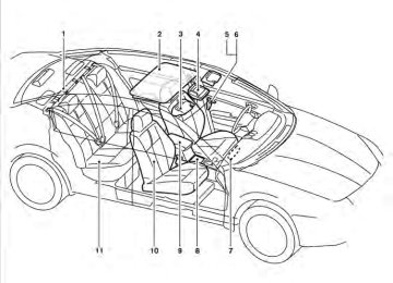
If your vehicle is stolen . . . . . . . . . . . . . . . . . . . . . . . . . 2-55INSTRUMENT PANEL
1. 2.
3.
Side and center vents (P. 4-40) Headlight/fog light (if so equipped)/turn signal switch (P. 2-28) Steering wheel switch for audio control and Bluetooth姞 Hands-Free Phone System (P. 4-113, 4-115)
2-2 Instruments and controls
Shift paddles (if so equipped) (P. 5-14)
8. 9. Windshield wiper/washer switch
(P. 2-26)
10. Display screen/Navigation system*
(if so equipped) (P. 4-16)
11. Display screen/Navigation system* controls (if so equipped) (P. 4-16)
12. Front passenger supplemental air bag
(P. 1-52)
13. Glove box (P. 2-40) 14. Display screen (models without
Navigation system) (P. 4-4)
15. Climate controls (models without
Navigation system) (P. 4-41)
16. Audio system controls (models without
Navigation system) (P. 4-47)
17. Front passenger air bag status light
(P. 1-44)
18. Audio system controls (P. 4-47) 19. Climate controls (models with Navigation system) (P. 4-44)
20. Shift selector (P. 5-11) 21. Hazard warning flasher switch (P. 2-33) 22.
Ignition switch (behind the steering wheel) (P. 5-7)
23. Tilt/telescopic steering wheel controls
(if so equipped) (P. 3-23)
WIC1535
4. Meters and gauges (P. 2-3) 5.
Driver supplemental air bag/horn (P. 1-37, P. 2-33) Security indicator light (P. 2-24) Cruise control main/set switches (P. 5-18)
6. 7.
METERS AND GAUGES
24. Vehicle Dynamic Control (VDC) OFF
switch (P. 2-36) Outside mirror controls (P. 3-28) Heated steering wheel switch (if so equipped) (P. 2-34) Trunk lid release switch (P. 3-20)
* Refer to the separate Navigation System Own- er’s Manual (if so equipped). See the page number indicated in paren- theses for operating details.
Tachometer Speedometer
1. 2. 3. Warning/indicator lights 4. 5. Odometer/twin trip odometer 6. Trip odometer change button
Fuel gauge
7. 8.
Engine coolant temperature gauge Vehicle information display
LIC1381
Instruments and controls 2-3
Changing the display: Press the change button 䊊3 to change the dis- play as follows: → Trip
→ Trip Trip Resetting the trip odometer: Press the change button 䊊3 for more than 1
second to reset the currently displayed trip odometer to zero. Elapsed time, driving distance and average speed information is also available. Refer to “Control panel buttons” in the “Monitor, climate, audio, phone and voice recognition systems” section in this manual.LIC1382
LIC1383
SPEEDOMETER AND ODOMETER Speedometer The speedometer indicates the vehicle speed.
Odometer/Twin trip odometer The odometer/twin trip odometer is displayed when the ignition switch is placed in the ON position. The odometer 䊊1 records the total distance the vehicle has been driven. The twin trip odometer 䊊2 records the distance of individual trips.
2-4 Instruments and controls
LIC1384
TACHOMETER The tachometer indicates engine speed in revo- lutions per minute (rpm). Do not rev the engine into the red zone 䊊1 .
CAUTION
When engine speed approaches the red zone, shift to a higher gear or reduce en- gine speed. Operating the engine in the red zone may cause serious engine damage.
LIC1386
ENGINE COOLANT TEMPERATURE GAUGE The gauge indicates the engine coolant tempera- ture. The engine coolant temperature is within the normal range 䊊1 when the gauge needle points within the zone shown in the illustration.The engine coolant temperature varies with the outside air temperature and driving conditions.
CAUTION
If the gauge indicates coolant tempera- ture near the hot (H) end of the normal range, reduce vehicle speed to decrease temperature. If the gauge is over the nor- mal range, stop the vehicle as soon as safely possible. If the engine is over- heated, continued operation of the ve- hicle may seriously damage the engine. See “If your vehicle overheats” in the “In case of emergency” section for immediate action required.
Instruments and controls 2-5
COMPASS DISPLAY (if so equipped)
This unit measures terrestrial magnetism and in- dicates the heading direction of the vehicle. With the ignition placed in the ON position, press button as described in the charts be- the low to activate various features of the automatic anti-glare rearview mirror.
Push and hold the button for about: 1 second
8 seconds
10 seconds
Feature: (Push button again for about 1 sec- ond to change settings) Compass display toggles on/off Compass zone can be changed to correct false compass readings Compass enters calibration mode
For information about the automatic anti-glare feature, refer to “Automatic anti-glare rearview mirror” in the “Pre-driving checks and adjust- ments” section.
The located on the driver’s side of the vehicle.
indicates that the fuel-filler door is
CAUTION
● If
the vehicle runs out of
fuel, Malfunction Indicator Light the (MIL) may come on. Refuel as soon as possible. After a few driving trips, light should turn off. If the the light remains on after a few driving trips, have the vehicle inspected by a NISSAN dealer.
● For additional information, see “Mal- function Indicator Light (MIL)” later in this section.
LIC1385
FUEL GAUGE The gauge indicates the approximate fuel level in the tank.
The gauge may move slightly during braking, turning, acceleration, or going up or down hills.
The gauge needle returns to E (Empty) after the ignition is placed in the OFF position.
The low fuel warning light comes on when the amount of fuel in the tank is getting low. Refill the fuel tank before the gauge regis- ters E (Empty).
2-6 Instruments and controls
You can also calibrate the compass by driving your vehicle on your everyday route. The com- pass will be calibrated once it has tracked three complete circles.
LIC1487
COMPASS DISPLAY
button for about 1 second when Push the the ignition switch is placed in the ON position to toggle the outside temperature and compass direction display 䊊1 on or off. The display will indicate the direction that the vehicle is heading.
N: North E: East S: South W: West
If the display reads “C”, calibrate the compass by driving the vehicle in three complete circles at less than 5 MPH (8 km/h).
Instruments and controls 2-7
Zone variation change procedure The difference between magnetic north and geo- graphical north is known as variance. In some areas, this difference can sometimes be great enough to cause false compass readings. Follow these instructions to set the variance for your particular location if this happens:
1. Press and hold the
button for about 8
seconds. The current zone number will ap- pear in the display. Release the button.2. Find your current location on the zone map.
Refer to the illustration.
3. Press the
button repeatedly to toggle through the zone numbers until the desired number appears in the display. Once you have selected a zone number, the display will show a compass direction within a few seconds.
NOTE:
Use zone number 5 for Hawaii.
Inaccurate compass direction
The compass display is equipped with automatic correction function. If the correct direction is not shown, follow this procedure.
2-8 Instruments and controls
WIC0355
1. With the display turned on, press and hold the for about 10 seconds. The “C” icon in the compass display will illuminate. 2. Calibrate the compass by driving the vehicle in three complete circles at a maximum speed of 5 MPH (8 km/h).
3. After completing the circles,
should return to normal.
the display
CAUTION
● Do not install a ski rack, antenna, etc., which are attached to the vehicle by means of a magnet. They affect the op- eration of the compass.
● When cleaning the mirror, use a paper towel or similar material dampened with glass cleaner. Do not spray glass cleaner directly on the mirror as it may cause the liquid cleaner to enter the mirror housing.
Instruments and controls 2-9
WARNING/INDICATOR LIGHTS AND AUDIBLE REMINDERS
or
or
Anti-lock Braking System (ABS) warning light
Brake warning light
Supplemental air bag warning light
Security indicator light
Continuously Variable Transmission (CVT) indicator light
Side light and headlight indicator light (green)
Charge warning light
Continuously Variable Transmission (CVT) position indicator light
Slip indicator light
Engine oil pressure warning light
Cruise main switch indicator light
Turn signal/hazard indicator lights
Low tire pressure warning light
Front passenger air bag status light
Vehicle Dynamic Control OFF indicator light
Master warning light
High beam indicator light (blue)
Seat belt warning light and chime
Malfunction Indicator Light (MIL)
CHECKING BULBS With all doors closed, apply the parking brake and place the ignition switch in the ON position without starting the engine. The following lights will come on:
or
2-10 Instruments and controls
If equipped, the following lights come on briefly and then go off:
or
If any light fails to come on, it may indicate a burned-out bulb or an open circuit in the electrical system. Have the system repaired promptly. WARNING LIGHTS For additional information on warnings and indi- cators, see “Vehicle information display” later in this section.
or
Anti-lock Braking System (ABS) warning light
When the ignition switch is placed in the ON position, the Anti-lock Braking System (ABS) warning light illuminates and then turns off. This indicates the ABS is operational.
If the ABS warning light illuminates while the engine is running, or while driving, it may indicate the ABS is not functioning properly. Have the system checked by a NISSAN dealer.
If an ABS malfunction occurs, the anti-lock func- tion is turned off. The brake system then operates normally, but without anti-lock assistance. See “Brake system” in the “Starting and driving” sec- tion.
or
Brake warning light
This light functions for both the parking brake and the foot brake systems. Parking brake indicator
When the ignition switch is placed in the ON position, the light comes on when the parking brake is applied.
Low brake fluid warning light
When the ignition switch is placed in the ON position, the light warns of a low brake fluid level. If the light comes on while the engine is running with the parking brake not applied, stop the ve- hicle and perform the following:
1. Check the brake fluid level. Add brake fluid as necessary. See “Brake fluid” in the “Main- tenance and do-it-yourself” section of this manual.
2.
If the brake fluid level is correct, have the warning system checked by a NISSAN dealer.
WARNING
● Your brake system may not be working properly if the warning light is on. Driv- ing could be dangerous. If you judge it to be safe, drive carefully to the nearest service station for repairs. Otherwise, have your vehicle towed because driv- ing it could be dangerous.
● Pressing the brake pedal with the en- gine stopped and/or a low brake fluid level may increase your stopping dis- tance and braking will require greater pedal effort as well as pedal travel.
● If the brake fluid level
is below the MINIMUM or MIN mark on the brake fluid reservoir, do not drive until the brake system has been checked at a NISSAN dealer.
Anti-lock Braking System (ABS) warning indicator
When the parking brake is released and the brake fluid level is sufficient, if both the brake warning light and the Anti-lock Braking System (ABS) warning light illuminate, it may indicate the ABS is not functioning properly. Have the brake system checked, and if necessary, repaired by a NISSAN dealer promptly. Avoid high-speed driv- ing and abrupt braking. (See “Anti-lock Braking System (ABS) warning light” in this section.)
Charge warning light
If this light comes on while the engine is running, it may indicate the charging system is not func- tioning properly. Turn the engine off and check the generator belt. If the belt is loose, broken, missing, or if the light remains on, see a NISSAN dealer immediately.
Instruments and controls 2-11
CAUTION
CAUTION
● Do not ground electrical accessories directly to the battery terminal. Doing so will bypass the variable control sys- tem and the vehicle battery may not charge completely. Refer to “Variable voltage control system” in the “Mainte- nance and do-it-yourself” section later in this manual.
● Do not continue driving if the generator
belt is loose, broken or missing.
Engine oil pressure warning light
This light warns of low engine oil pressure. If the light flickers or comes on during normal driving, pull off the road in a safe area, stop the engine immediately and call a NISSAN dealer or other authorized repair shop. The engine oil pressure warning light is not designed to indicate a low oil level. Use the dipstick to check the oil level. See “Engine oil” in the “Maintenance and do-it-yourself” section of this manual.
2-12 Instruments and controls
Running the engine with the engine oil pressure warning light on could cause se- rious damage to the engine almost imme- diately. Such damage is not covered by warranty. Turn off the engine as soon as it is safe to do so.
Low tire pressure warning light
Your vehicle is equipped with a Tire Pressure Monitoring System (TPMS) that monitors the tire pressure of all tires except the spare.
The low tire pressure warning light warns of low tire pressure or indicates that the TPMS is not functioning properly.
After the ignition switch is placed in the ON position, this light illuminates for about 1 second and turns off. Low tire pressure warning:
If the vehicle is being driven with low tire pressure, the warning light will illuminate. A CHECK TIRE PRESSURE warning also appears in the vehicle information display. When the low tire pressure warning light illuminates, you should stop and adjust the tire pressure of all 4 tires to the recom-
mended COLD tire pressure shown on the Tire and Loading Information label located in the driver’s door opening. The low tire pressure warning light does not automati- cally turn off when the tire pressure is ad- justed. After the tire is inflated to the rec- ommended pressure, the vehicle must be driven at speeds above 16 MPH (25 km/h) to activate the TPMS and turn off the low tire pressure warning light. Use a tire pres- sure gauge to check the tire pressure. The CHECK TIRE PRESSURE warning is active as long as the low tire pressure warning light remains illuminated. For additional information, see “Vehicle informa- tion display” in the “Instruments and controls” section and “Tire Pressure Monitoring System (TPMS)” in the “Starting and driving” section and in the “In case of emergency” section. TPMS malfunction: If the TPMS is not functioning properly, the low tire pressure warning light will flash for approxi- mately 1 minute when the ignition switch is placed in the ON position. The light will remain on after the 1 minute. Have the system checked by a NISSAN dealer. The CHECK TIRE PRESSURE warning does not appear if the low tire pressure warning light illuminates to indicate a TPMS mal- function.
For additional information, see “Tire Pressure Monitoring System (TPMS)” in the “Starting and driving” section and “Tire pressure” in the “Mainte- nance and do-it-yourself” section in this manual.
WARNING
● If the light does not illuminate with the ignition switch in the ON position, have the vehicle checked by a NISSAN dealer as soon as possible.
● If the light illuminates while driving, avoid sudden steering maneuvers or abrupt braking, reduce vehicle speed, pull off the road to a safe location and stop the ve- hicle as soon as possible. Driving with under-inflated tires may permanently damage the tires and increase the likeli- hood of tire failure. Serious vehicle dam- age could occur and may lead to an acci- dent and could result in serious personal injury. Check the tire pressure for all four tires. Adjust the tire pressure to the rec- ommended COLD tire pressure shown on the Tire and Loading Information label located in the driver’s door opening to turn the low tire pressure warning light OFF. If the light still comes on while driv- ing after adjusting the tire pressure, a tire may be flat. If you have a flat tire, replace it with a spare tire as soon as possible.
● When a spare tire is mounted or a wheel is replaced, tire pressure will not be indicated, the TPMS will not function and the low tire pressure warning light will flash for approximately 1 minute. The light will remain on after 1 minute. Contact your NISSAN dealer as soon as possible for tire replacement and/or system resetting.
● Replacing tires with those not originally specified by NISSAN could affect the proper operation of the TPMS.
CAUTION
● The TPMS is not a substitute for the regular tire pressure check. Be sure to check the tire pressure regularly.
● If the vehicle is being driven at speeds of less than 16 MPH (25 km/h), the TPMS may not operate correctly.
● Be sure to install the specified size of
tires to the 4 wheels correctly.
Master warning light
This light comes on when various vehicle infor- mation display warnings appear.
Seat belt warning light and chime
The light and chime remind you to fasten your seat belts. The light illuminates whenever the ignition switch is placed in the ON or START position and remains illuminated until the driver’s seat belt is fastened. At the same time, the chime sounds for about 6 seconds unless the driver’s seat belt is securely fastened. The seat belt warning light may also illuminate if the front passenger’s seat belt is not fastened when the front passenger’s seat is occupied. For 7 seconds after the ignition switch is placed in the ON position, the system does not activate the warning light for the front passenger. Refer to “Seat belts” in the “Safety—Seats, seat belts and supplemental restraint system” section for precautions on seat belt usage.
Supplemental air bag warning light
When the ignition switch is placed in the ON or START position, the supplemental air bag warn- ing light illuminates for about 7 seconds and then turns off. This means the system is operational.
Instruments and controls 2-13
If any of the following conditions occur, the front air bag, side air bag, curtain air bag, and preten- sioner seat belt systems need servicing and your vehicle must be taken to a NISSAN dealer: ● The supplemental air bag warning light re-
mains on after approximately 7 seconds.
● The supplemental air bag warning light
flashes intermittently.
● The supplemental air bag warning light does
not come on at all.
Unless checked and repaired, the supplemental restraint system (air bag system) and/or the pre- tensioners may not function properly. For addi- tional details see “Supplemental restraint sys- tem” in the “Safety—Seats, seat belts and supplemental restraint system” section of this manual.
WARNING
If the supplemental air bag warning light is on, it could mean that the front air bag, side air bag, curtain air bag systems and/or pretensioner systems will not op- erate in an accident. To help avoid injury to yourself or others, have your vehicle checked by a NISSAN dealer as soon as possible.
2-14 Instruments and controls
INDICATOR LIGHTS
Continuously Variable Transmission (CVT) indicator light
When the ignition switch is placed in the ON position, the light comes on for 2 seconds.
Continuously Variable Transmission (CVT) position indicator light
When the ignition switch is placed in the ON position, the indicator light shows the shift selec- tor position. See “Driving the vehicle” in the “Starting and driving” section of this manual. Cruise main switch indicator light
The light comes on when the cruise control main switch is pushed. The light goes out when the main switch is pushed again. When the cruise main switch indicator light comes on, the cruise control system is operational.
Front passenger air bag status light
The front passenger air bag status light will be lit and the passenger front air bag will be OFF depending on how the front passenger seat is being used. For front passenger air bag status light operation, see “Front passenger air bag and status light” in the “Safety — Seats, seat belts and supplemental restraint system” section of this manual. High beam indicator light (blue)
This blue light comes on when the headlight high beams are on and goes out when the low beams are selected. The high beam indicator light also comes on when the passing signal is activated.
Malfunction indicator light (MIL)
If the malfunction indicator light comes on steady or blinks while the engine is running, it may indi- cate a potential emission control and/or CVT malfunction.
The malfunction indicator light may also come on steady if the fuel-filler cap is loose or missing, or if the vehicle runs out of fuel. Check to make sure the fuel-filler cap is installed and closed tightly, and that the vehicle has at least 3 gallons (11.4
liters) of fuel in the fuel tank.light should After a few driving trips, the turn off if no other potential emission control system malfunction exists.
If this indicator light comes on steady for 20
seconds and then blinks for 10 seconds when the engine is not running, it indicates that the vehicle is not ready for an emission control sys- tem inspection/maintenance test. See “Readi- ness for inspection/maintenance (I/M) test” in the “Technical and consumer information” section of this manual. OperationThe malfunction indicator light will come on in one of two ways:
● Malfunction indicator light on steady — An emission control system and/or CVT mal- function has been detected. Check the fuel- filler cap if the LOOSE FUEL CAP warning appears in the vehicle information display. If the fuel-filler cap is loose or missing, tighten or install the cap and continue to drive the light should turn off after vehicle. The a few driving trips. If the light does not turn off after a few driving trips, have the vehicle inspected by a NISSAN dealer. You do not need to have your vehicle towed to the dealer.
● Malfunction indicator light blinking — An en- gine misfire has been detected which may damage the emission control system. To re- duce or avoid emission control system dam- age: – do not drive at speeds above 45 MPH
(72 km/h).
– avoid hard acceleration or deceleration. – avoid steep uphill grades. – if possible, reduce the amount of cargo
being hauled or towed.
The malfunction indicator light may stop blinking and come on steady. Have the vehicle inspected by a NISSAN dealer. You do not need to have your vehicle towed to the dealer.
CAUTION
Continued vehicle operation without hav- ing the emission control system checked and repaired as necessary could lead to poor driveability, reduced fuel economy, and possible damage to the emission con- trol system.
Security indicator light
This light blinks when the ignition switch is placed in the OFF, LOCK or ACC position. The blinking security indicator light indicates that the security systems equipped on the vehicle are operational. For additional tems” later in this section.
information, see “Security sys-
Side light and headlight indicator light (green)
The side light and headlight indicator light illumi- nates when the side light or headlight position is selected. See “Headlight and turn signal switch” later in this section for further details.
Instruments and controls 2-15
Light reminder chime With the ignition switch placed in the OFF posi- tion, a chime sounds when the driver’s door is opened if the headlights or parking lights are on. Turn the headlight control switch off before leav- ing the vehicle. NISSAN Intelligent Key™ door buzzer The Intelligent Key door buzzer sounds if the Intelligent Key is left inside the vehicle when locking the doors. When the buzzer sounds, be sure to check both the vehicle and the Intelligent Key. See “NISSAN Intelligent Key™” in the “Pre- driving checks and adjustments” section.
Slip indicator light
This indicator will blink when the VDC system or the traction control system is operating, thus alerting that the vehicle is nearing its traction limits. The road surface may be slippery.
Turn signal/hazard indicator lights
The appropriate light flashes when the turn signal switch is activated.
Both lights flash when the hazard switch is turned on.
Vehicle Dynamic Control (VDC) OFF indicator light
This indicator light comes on when the Vehicle Dynamic Control off switch is pushed to OFF. This indicates the Vehicle Dynamic Control has been turned off. Push the Vehicle Dynamic Control off switch again or restart the engine and the system will be reactivated. See “Vehicle Dynamic Control (VDC) system” in the “Starting and driving” sec- tion of this manual. The Vehicle Dynamic Control light also comes on when you push the push-button ignition switch to 2-16 Instruments and controls
the ON position. The light will turn off after about 2 seconds if the system is operational. If the light indi- stays on or comes on along with the cator light while you are driving, have the Vehicle Dynamic Control system checked by a NISSAN dealer.
While the Vehicle Dynamic Control system is operating, you might feel slight vibration or hear the system working when starting the vehicle or accelerating, but this is normal. AUDIBLE REMINDERS Brake pad wear warning The disc brake pads have audible wear warnings. When a disc brake pad requires replacement, it makes a high pitched scraping sound when the vehicle is in motion, whether or not the brake pedal is depressed. Have the brakes checked as soon as possible if the warning sound is heard. Key reminder chime A chime sounds if the driver’s door is opened while the ignition switch is placed in the ACC or OFF position or placed in the OFF or LOCK position with the Intelligent Key left in the Intelli- gent Key port. Make sure the ignition switch is placed in the LOCK position, and take the Intel- ligent Key with you when leaving the vehicle.
VEHICLE INFORMATION DISPLAY
WIC1102
The vehicle information display 䊊1 is located on the bottom of the speedometer. It displays such items as: ● Intelligent Key operation information ● some indicators and warnings ● other information For details about the Intelligent Key, see “NISSAN Intelligent Key™” in the “Pre-driving checks and adjustments” section.WIC1406
LIC1093
HOW TO USE THE VEHICLE INFORMATION DISPLAY Press the button, located on the instru- ment panel just behind the steering wheel, to display the following modes: MPG → MPG/MPH → Time/Miles → Range → Exterior Temperature → Setting → Warning
Fuel economy mode The fuel economy mode can be selected to dis- play the instant fuel economy since the last reset.
Instruments and controls 2-17
LIC1097
WIC1266
LIC1095
Average speed mode The average speed mode can be selected to display the average miles per gallon and miles per hour since the last reset.
Time/Miles (km) mode The time/miles (km) mode can be selected to show the time and distance driven since the last reset.
Range mode The range mode can be selected to give you an estimation of the distance that can be driven before refueling. The range is constantly calcu- lated based on the amount of fuel in the fuel tank and the actual fuel consumption.
2-18 Instruments and controls
LIC1096
LIC1541
LIC1044
Exterior temperature mode The exterior temperature mode can be selected to provide you with the temperature outside of your vehicle.
Setting mode The setting mode allows you to set reminders or preferences for alerts, maintenance intervals or language displays.
to move
In the setting mode screen press to: ● Alert ● Maintenance ● Options
and press
to select the menu.
Alert mode The alert mode allows you to set alerts notifying you of time to rest or icy conditions. The time to rest alert lets you know when you have been traveling for a long time and may need a break. The icy alert notifies you that icy driving condi- tions may exist.
Instruments and controls 2-19
LIC1046
LIC1045
LIC1542
Reset mode The reset mode can be selected in any screen that allows for preferences to be programmed. Once the screen is selected, you have the option to reset the selected distances or time to a new setting.
2-20 Instruments and controls
Maintenance mode The maintenance mode allows you to set alerts for the reminding of maintenance intervals for the following: ● engine oil ● oil filter ● tires ● other
to high- Set a desired interval by pushing light the maintenance field and pressing The reset mode will open up and allow you to enter the desired distance.
Options mode
The LANGUAGE/UNIT screen will appear when selecting and pressing Language: English or French
“Language/Unit”
the
key
Unit: US — mile, °F, MPG
Metric — km, °C, L/100 km
Dial effects: This changes effects of the indicator needles when ON. The needles in the meter sweep and the ring illumination will be brightened gradually when the engine is started.
You can select the language, unit or change the dial effects by using the button and pressing The settings are automatically saved when you exit the menu by pressing the BACK button or any other mode button.
LIC1098
Warning mode The warning mode can be selected to view any warnings that may be present. Once the screen is selected you have the option of skipping the warning or viewing it in detail. Warnings can be present for issues such as an open door or low fuel. For more information about potential warnings see “Vehicle information dis- play warnings and indicators” later in this section.
Instruments and controls 2-21
Vehicle information display warnings and indicators 1. Door and trunk open warning 2. Push warning 3. Low fuel warning 4. Low windshield-washer fluid warning 2-22 Instruments and controls
5. No key warning 6. Parking brake warning 7. Shift P warning 8. Engine start operation indicator 9. NISSAN Intelligent Key™ insertion indicator
LIC2008
10. NISSAN Intelligent Key™ removal indicator11. NISSAN Intelligent Key™ battery discharge
indicator
12. Loose fuel cap warning
13. Check tire pressure warning
Door and trunk open warning
No key warning
SHIFT P warning
This warning illuminates when a door or the trunk has been opened when the engine is running. Push warning
After the Shift P warning illuminates, the Push warning will illuminate if the ignition switch is placed in the ACC position when the shift selec- tor is moved to the P (Park) position.
See “Shift P warning” in this section for additional information.
To turn off the Push warning, place the ignition switch in the ON position and then to the LOCK position. Low fuel warning This warning illuminates when the fuel level in the fuel tank is getting low. Refuel as soon as it is convenient, preferably before the fuel gauge reaches E (Empty). There will be a small re- serve of fuel in the tank when the fuel gauge needle reaches E (Empty). Low windshield-washer fluid warning This warning illuminates when the windshield- washer fluid is at a low level. Add windshield- washer fluid as necessary. See “Windshield- washer fluid” in the “Maintenance and do-it- yourself” section of this manual.
This warning illuminates following two condi- tions:
1. When the ignition switch is pushed and the Intelligent Key cannot be recognized by the system. If this warning illuminates, you can- not start the engine.
Check for the following causes and perform the assigned remedies:
This warning illuminates when the ignition switch is pushed to stop the engine with the shift selec- tor in any position except in the P (Park) position.
If this warning illuminates, the ignition switch is in the OFF position. Move the shift selector to the P (Park) position or push the ignition switch to the ON position.
An inside warning chime will also sound.
– The battery of the Intelligent Key carried with you is discharged completely. Re- place the battery with a new one.
If the shift selector is moved to the P (Park) position, the Push warning will appear. Refer to “Push warning” in this section.
– The Intelligent Key carried with you is not registered to the system. Use the regis- tered Intelligent Key.
– You do not have an Intelligent Key with
you. Carry an Intelligent Key with you.
2. When the door is closed with the Intelligent Key left outside the vehicle and the ignition switch is placed in the ACC or ON position. A chime will also sound.
Parking brake warning
This warning illuminates when the parking brake is set and the vehicle is driven.
For additional information about Intelligent Key, see “NISSAN Intelligent Key™” in the “Pre-driving checks and adjustments” section. Engine start operation indicator
This indicator illuminates when the ignition switch is in the LOCK, OFF, ACC or ON position with the shift selector in the P (Park) position.
This indicator means that the engine will start by pushing the push-button ignition switch with the brake pedal depressed.
Instruments and controls 2-23
Loose fuel cap warning This warning appears when the fuel-filler cap is not tightened correctly after the vehicle has been refueled. See “Fuel-filler cap” in the “Pre-driving checks and adjustments” section. Check tire pressure warning This warning appears when the low tire pressure warning light in the meter illuminates and low tire pressure is detected. If this warning appears, stop the vehicle and adjust the tire pressure to the recommended COLD tire pressure shown on the Tire and Loading Information label. See “Low tire pressure warning light” earlier in this section and “Tire Pressure Monitoring System (TPMS)” in the “Starting and driving” section.
NISSAN Intelligent Key™ insertion indica- tor
This indicator illuminates when the Intelligent Key needs to be inserted into the Intelligent Key port. (For example, the Intelligent Key battery is dis- charged.) If this indicator illuminates, insert the Intelligent Key into the Intelligent Key port in the correct direction. See “Push-button ignition switch” in the “Starting and driving” section. NISSAN Intelligent Key™ removal indica- tor This indicator illuminates when the driver’s door is opened with the ignition switch placed in the OFF position and the Intelligent Key placed in the Intelligent Key port. A key reminder chime also sounds. If this indicator illuminates, remove the Intelligent Key from the Intelligent Key port and take it with you when leaving the vehicle. NISSAN Intelligent Key™ battery dis- charge indicator This indicator illuminates when the Intelligent Key battery is running out of power. If this indicator illuminates, replace the battery with a new one. See “NISSAN Intelligent Key™” in the “Maintenance and do-it-yourself” section. 2-24 Instruments and controls
SECURITY SYSTEMS
LIC0301
Your vehicle has two types of security systems: ● Vehicle security system ● NISSAN Vehicle Immobilizer System VEHICLE SECURITY SYSTEM The vehicle security system provides visual and audible alarm signals if someone opens the doors or trunk lid when the system is armed. It is not, however, a motion detection type system that activates when a vehicle is moved or when a vibration occurs. The system helps deter vehicle theft but cannot prevent it, nor can it prevent the theft of interior or exterior vehicle components in all situations. Al-ways secure your vehicle even if parking for a brief period. Never leave your Intelligent Key in the vehicle, and always lock the vehicle when unattended. Be aware of your surroundings, and park in secure, well-lit areas whenever possible. Many devices offering additional protection, such as component locks, identification markers, and tracking systems, are available at auto supply stores and specialty shops. Your NISSAN dealer may also offer such equipment. Check with your insurance company to see if you may be eligible for discounts for various theft protection features. How to arm the vehicle security system 1. Close all windows. (The system can be armed even if the windows are open.) 2. Remove the Intelligent Key from the vehicle. 3. Close all doors, hood and trunk. Lock all doors. The doors can be locked with the Intelligent Key, door handle request switch, power door lock switch or mechanical key. light comes on. The security light stays on for about 30 seconds. The vehicle security sys- tem is now pre-armed. After about 30 sec- onds the vehicle security system automati- cally shifts into the armed phase. The security light begins to flash once every 3
seconds. If, during the 30-second pre-armthe security indicator
4. Confirm that
time period, the driver’s door is unlocked by the key or the keyfob, or the ignition switch is placed in the ACC or ON position, the sys- tem will not arm.
● Even when the driver and/or passengers are in the vehicle, the system will acti- vate with all the doors, hood and trunk lid locked with the ignition switch placed in the LOCK position. When plac- ing the ignition switch in the ACC or ON position, the system will be released.
Vehicle security system activation The vehicle security system will give the following alarm: ● The headlights blink and the horn sounds
intermittently.
● The alarm automatically turns off after ap- proximately 50 seconds. However, the alarm reactivates if the vehicle is tampered with again. The alarm can be shut off by unlocking the driver’s door or trunk lid with the key, or button on the Intelli- by pressing the gent Key.
The alarm is activated by: ● opening the door or trunk lid without using the key or Intelligent Key (even if the door is unlocked by releasing the door inside lock switch).
How to stop an activated alarm The alarm stops only by unlocking the driver’s door or the trunk lid with the key, pressing button on the Intelligent Key, or press- the ing the request switch on the driver’s or passen- ger’s door with the Intelligent Key in range of the door handle. NISSAN VEHICLE IMMOBILIZER SYSTEM The NISSAN Vehicle Immobilizer System will not allow the engine to start without the use of a registered key. If the engine fails to start using a registered key (for example, when interference is caused by another registered key, an automated toll road device or automatic payment device on the key ring), restart the engine using the following pro- cedures: 1. Leave the ignition switch placed in the ON
position for approximately 5 seconds.
2. Place the ignition switch in the OFF or LOCK position and wait approximately 10
seconds.3. Repeat steps 1 and 2.
Instruments and controls 2-25
4. Restart the engine while holding the device (which may have caused the interference) separate from the registered key.
If the no start condition re-occurs, NISSAN rec- ommends placing the registered key on a sepa- rate key ring to avoid interference from other devices. Statement related to Section 15 of FCC Rules for NISSAN Vehicle Immobilizer Sys- tem (CONT ASSY — IMMOBILIZER, ANT ASSY — IMMOBILIZER) This device complies with part 15 of the FCC Rules and RSS-210 of Industry Canada. Operation is subject to the follow- ing two conditions; (1) This device may not cause harmful in- terference, and (2) this device must accept any interference received, including inter- ference that may cause undesired opera- tion of the device. CHANGES OR MODIFICATIONS NOT EX- PRESSLY APPROVED BY THE PARTY RE- SPONSIBLE FOR COMPLIANCE COULD VOID THE USER’S AUTHORITY TO OPER- ATE THE EQUIPMENT.
2-26 Instruments and controls
WINDSHIELD WIPER AND WASHER SWITCH
LIC0474
WIC1434
Security indicator light The security indicator light blinks whenever the ignition switch is placed in the OFF, LOCK or ACC position. This function indicates the NISSAN Ve- hicle Immobilizer System is operational. If the NISSAN Vehicle Immobilizer System is mal- functioning, the light will remain on while the ignition switch is placed in the ON position. If the light still remains on and/or the en- gine will not start, see a NISSAN dealer for NISSAN Vehicle Immobilizer System ser- vice as soon as possible. Please bring all registered keys that you have when visiting your NISSAN dealer for service.
SWITCH OPERATION The windshield wiper and washer operates when the ignition switch is in the ON position.
Push the lever down to operate the wiper at the following speed: 䊊1
Intermittent — intermittent operation can be adjusted by turning the knob toward 䊊A (Slower) or 䊊B (Faster). Also, the intermit- tent operation speed varies in accordance with the vehicle speed. (For example, when the vehicle speed is high, the intermittent operation speed will be faster.)
NOTE: You can turn on or turn off the driving speed dependent intermittent wiper func- tion for vehicles with navigation system. Refer to “Comfort settings” in the “Monitor, climate, audio, phone and voice recogni- tion systems” section. 䊊2
Low — continuous low speed operation 䊊3 High — continuous high speed operation Push the lever up 䊊4 to have one sweep opera- tion of the wiper. Pull the lever toward you 䊊5
to operate the washer. The wiper will also operate several times.WARNING
In freezing temperatures the washer solu- tion may freeze on the windshield and obscure your vision which may lead to an accident. Warm the windshield with the defroster before you wash the windshield.
REAR WINDOW AND OUTSIDE MIRROR (if so equipped) DEFROSTER SWITCH
CAUTION
● Do not operate the washer continu-
ously for more than 30 seconds. ● Do not operate the washer
if
fluid reservoir
the is
windshield-washer empty.
● Do not fill the windshield-washer fluid reservoir with washer fluid concen- trates at full strength. Some methyl al- cohol based washer fluid concentrates may permanently stain the grille if spilled while filling the windshield- washer fluid reservoir.
● Pre-mix washer fluid concentrates with water to the manufacturer’s recom- mended levels before pouring the fluid into the windshield-washer fluid reser- voir. Do not use the windshield-washer fluid reservoir to mix the washer fluid and water.
Type A
LIC1387
To defrost the rear window glass and outside mirrors (if so equipped), start the engine and push the rear window defroster switch on. The rear window defroster light on the switch comes on. Push the switch again to turn the defroster off.
indicator
The rear window defroster automatically turns off after approximately 15 minutes.
CAUTION
When cleaning the inner side of the rear window, be careful not to scratch or dam- age the rear window defroster.
Instruments and controls 2-27
● The life of xenon headlights will be shortened by frequent on-off opera- tion. It is generally desirable not to turn off the headlights for short intervals (for example, when the vehicle stops at a traffic signal).
● If the xenon headlight bulb is close to burning out, the brightness will drasti- cally decrease, the light will start blink- ing, or the color of the light will be- come reddish. If one or more of the above signs appear, contact a NISSAN dealer.
HEADLIGHT AND TURN SIGNAL SWITCH
XENON HEADLIGHTS (if so equipped)
WARNING
ᏘHIGH VOLTAGE
● When xenon headlights are on, they produce a high voltage. To prevent an electric shock, never attempt to modify or disassemble. Always have your xe- non headlights replaced at a NISSAN dealer.
● Xenon headlights provide considerably more light than conventional head- lights. If they are not correctly aimed, they might temporarily blind an oncom- ing driver or the driver ahead of you and cause a serious accident. If headlights are not aimed correctly, immediately take your vehicle to a NISSAN dealer and have the headlights adjusted correctly.
When the xenon headlight is initially turned on, its brightness or color varies slightly. However, the color and brightness will soon stabilize.
Type B
LIC1388
NOTE: The top few rows of wires on the rear win- dow are not part of the rear window de- froster system. These wires make up the antenna for the audio system.
2-28 Instruments and controls
Type A
Type B
WIC1435
WIC1436
HEADLIGHT CONTROL SWITCH Lighting 䊊1 When turning the switch to the
posi- tion, the front parking, tail, license plate and instrument panel lights come on. 䊊2 When turning the switch to the
posi- tion, the headlights come on and all the other lights remain on.
CAUTION
Use the headlights with the engine run- ning to avoid discharging the vehicle battery.
Instruments and controls 2-29
To turn on the autolight system: 1. Place the headlight switch in the AUTO po-
sition 䊊1 .
2. Place ignition in the ON position. 3. The autolight system automatically turns the
headlights on and off.
Initially, if the ignition switch is placed in the OFF position and a door is opened and left open, the headlights remain ON for 5 minutes. If another door is opened during the 5 minutes, then the 5
minute timer is reset. To turn the autolight system off, turn the switch to the OFF,position.
, or
WHA1170
Be sure you do not put anything on top of the autolight sensor located on the top side of the instrument panel. The autolight sen- sor controls the autolight; if it is covered, the autolight sensor reacts as if it is dark out and the headlights will illuminate. If this occurs while parked with the engine off and the ignition switch placed in the ON position, your vehicle’s battery could be- come discharged.LIC1086
Autolight system The autolight system allows the headlights to be set so they turn on and off automatically. The autolight system can: ● Turn on the headlights, front parking, tail, license plate and instrument panel lights au- tomatically when it is dark.
● Turn off all the lights when it is light. ● Keep all the lights on for 45 seconds after you place the ignition switch in the OFF position and all doors are closed.
2-30 Instruments and controls
CAUTION
WARNING
Even though the battery saver feature au- tomatically turns off the headlights after a period of time, you should turn the head- light switch to the OFF position when the engine is not running to avoid discharging the vehicle battery.
DAYTIME RUNNING LIGHT SYSTEM (Canada only) The headlights automatically illuminate at a re- duced intensity when the engine is started with the parking brake released. The daytime running lights operate with the headlight switch in the position. Turn the OFF position or in the position for full headlight switch to the illumination when driving at night.
If the parking brake is applied before the engine is started, the daytime running lights do not illumi- nate. The daytime running lights illuminate when the parking brake is released. The daytime run- ning lights will remain on until the ignition switch is placed in the OFF position.
WIC1438
Headlight beam select 䊊1 To select the high beam function, push the lever forward. The high beam lights come on and the
light illuminates.
䊊2 Pull the lever back to select the low beam. 䊊3 Pulling and releasing the lever flashes the
headlight high beams on and off.
Battery saver system If the ignition switch is placed in the OFF position while the headlight switch is in the or 5 minutes.
position, the headlights will turn off after
When the daytime running light system is active, tail lights on your vehicle are not on. It is necessary at dusk to turn on your headlights. Failure to do so could cause an accident injuring yourself and others.
Instruments and controls 2-31
WIC1412
WIC1439
control
headlight or
INSTRUMENT BRIGHTNESS CONTROL The instrument cluster illuminates when the igni- tion switch is in the ON position. The instrument brightness control operates when the the AUTO, Turn the control left or right to adjust the bright- ness of the instrument panel lights when driving at night. The instrument brightness control will not adjust the brightness when the headlights or parking lights are off. 2-32 Instruments and controls
position.
switch
in
is
TURN SIGNAL SWITCH Turn signal 䊊1 Move the lever up or down to signal the turning direction. When the turn is com- pleted, the turn signals cancel automatically.
Lane change signal 䊊2 To signal a lane change, move the lever up or down to the point where the indicator light begins to flash, but the lever does not latch.
position.
WIC1440
FOG LIGHT SWITCH (if so equipped) To turn the fog lights on, turn the headlight switch position, then turn the fog light to the switch to the To turn the fog lights on with the headlight switch in the AUTO position, the headlights must be on, then turn the fog light switch to the To turn the fog lights off, turn the fog light switch to the OFF position. The headlights must be on and the low beams selected for the fog lights to operate. The fog lights automatically turn off when the high beam headlights are selected.position.
HAZARD WARNING FLASHER SWITCH
HORN
The flashers will operate with the ignition switch placed in any position. Some state laws may prohibit the use of the hazard warning flasher switch while driving.
LIC0394
Push the switch on to warn other drivers when you must stop or park under emergency condi- tions. All turn signal lights flash.WARNING
● If stopping for an emergency, be sure to
move the vehicle well off the road.
● Do not use the hazard warning flashers while moving on the highway unless unusual circumstances force you to drive so slowly that your vehicle might become a hazard to other traffic.
● Turn signals do not work when the haz-
ard warning flasher lights are on.
LIC1389
To sound the horn, push the center pad area of the steering wheel.WARNING
Do not disassemble the horn. Doing so could affect proper operation of the supplemental front air bag system. Tam- pering with the supplemental front air bag system may result in serious personal injury.
Instruments and controls 2-33
HEATED SEATS (if so equipped)
HEATED STEERING WHEEL (if so equipped)
CAUTION
● Do not use the seat heater for extended periods or when no one is using the seat.
● Do not put anything on the seat which insulates heat, such as a blanket, cush- ion, seat cover, etc. Otherwise, the seat may become overheated.
● Do not place anything hard or heavy on the seat or pierce it with a pin or similar object. This may result in damage to the heater.
● Any liquid spilled on the heated seat should be removed immediately with a dry cloth.
● When cleaning the seat, never use gasoline, benzine, thinner, or any simi- lar materials.
● If any abnormalities are found or the heated seat does not operate, turn the switch off and have the system checked by your NISSAN dealer.
● The battery could run down if the seat heater is operated while the engine is not running.
LIC0421
The heated steering wheel system is designed to operate only when the surface temperature of the steering wheel is below 68°F (20°C).Push the heated steering wheel switch to warm the steering wheel after the engine starts. The indicator light will come on.
If the surface temperature of the steering wheel is below 68°F (20°C), the system will heat the steering wheel and cycle off and on to maintain a temperature above 68°F (20°C). The indicator light will remain on as long as the system is on. Push the switch again to turn the heated steering wheel system off manually. The indicator light will go off.
LIC1543
The front seats are warmed by built-in heaters. The switch is located on the center console.1. Start the engine.
2. Push the LO or HI position of the switch, as desired. The indicator light in the switch will illuminate.
The heater is controlled by a thermostat, automatically turning the heater on and off. The indicator light will remain on as long as the switch is on.
3. When the seat is warmed or before you leave the vehicle, be sure to turn the switch off.
2-34 Instruments and controls
CLIMATE CONTROL SEAT SWITCH (if so equipped)
NOTE: If the surface temperature of the steering wheel is above 68°F (20°C) when the switch is turned on, the system will not heat the steering wheel. This is not a malfunction.
LIC1410
The climate controlled seat warms up or cools down the front seat by blowing warm or cool air from the surface of the seat. The climate control switch is located on the center console.The climate controlled seat can be operated as follows:
1. Start the engine.
2. Turn the control knob to the H (Heat) side or to the C (Cool) side, as desired. The indica- tor light on the control knob will illuminate.
3. Adjust the desired amount of air using the control knob. The climate controlled seat blower remains on low speed for approxi-
mately 60 seconds after turning the switch on or selecting the desired temperature.
4. When the vehicle’s interior is warmed or cooled, or before you leave the vehicle, be sure to turn the control knob to the Off (center) position
To check the air filter for the climate controlled seat, contact a NISSAN dealer.
CAUTION
● The battery could run down if the cli- mate control seat is operated while the engine is not running.
● Do not use the climate control seat for extended periods or when no one is using the seat.
● Do not put anything on the seat which insulates heat, such as a blanket, cush- ion, seat cover, etc. Otherwise, the seat may become overheated.
● Do not place anything hard or heavy on the seat or pierce it with a pin or similar objects. This may result in damage to the climate controlled seat.
● Any liquid spilled on the seat should be
removed immediately with a dry cloth
Instruments and controls 2-35
● The climate controlled seat has an air filter. Do not operate the climate con- trolled seat without an air filter. This may result in damage to the system.
● When cleaning the seat, never use gasoline, benzine, thinner, or any simi- lar materials.
● If any malfunctions are found or the climate controlled seat does not oper- ate, turn the switch off and have the system checked by your NISSAN dealer.
2-36 Instruments and controls
VEHICLE DYNAMIC CONTROL (VDC) OFF SWITCH
POWER OUTLET
LIC1548
The vehicle should be driven with the Vehicle Dynamic Control (VDC) system on for most driv- ing conditions. If the vehicle is stuck in mud or snow, the VDC system reduces the engine output to reduce wheel spin. The engine speed will be reduced even if the accelerator is depressed to the floor. If maximum engine power is needed to free a stuck vehicle, turn the VDC system off. To turn off the VDC system, push the VDC OFF switch. The Push the VDC OFF switch again or restart the engine to turn on the system. See “Vehicle Dy- namic Control (VDC) system” in the “Starting and driving” section.indicator will come on.
LIC1392
Front center console
The power outlets are for powering electrical accessories such as cellular telephones. They are rated at 12 Volt, 120 W (10A) maximum. The power outlet in the front console box is powered directly by the vehicle battery. The out- let on the center console near the shift selector is powered only when the ignition switch is in the ACC or ON position.
STORAGE
CAUTION
● The outlet and plug may be hot during
or immediately after use.
● The power outlets are not designed for
use with a cigarette lighter.
● Do not use with accessories that ex- ceed a 12 volt, 120W (10A) power draw. Do not use double adapters or more than one electrical accessory.
● Use power outlets with the engine run- ning to avoid discharging the vehicle battery.
● Avoid using power outlets when the air conditioner, headlights or rear window defroster is on.
● Before inserting or disconnecting a plug, be sure the electrical accessory being used is turned OFF.
● Push the plug in as far as it will go. If good contact is not made, the plug may overheat or the internal temperature fuse may open.
● When not in use, be sure to close the cap. Do not allow water or any other liquids to contact the outlet.
MAP POCKETS
LIC1393
LIC0016
SEATBACK POCKETS The seatback pockets are located on the back of the driver’s and passenger’s seats. The pockets can be used to store maps.
Instruments and controls 2-37
CAUTION
● Do not use for anything other than
sunglasses.
● Do not leave sunglasses in the sun- glasses holder while parking in direct sunlight. The heat may damage the sunglasses.
WIC1551
SUNGLASSES HOLDER To open the sunglasses holder, push and release. Only store one pair of sunglasses in the holder.
WARNING
Keep the sunglasses holder closed while driving to prevent an accident.
2-38 Instruments and controls
CUP HOLDERS
Front
LIC1395
CAUTION
● Avoid abrupt starting and braking when the cup holder is being used to prevent spilling the drink. If the liquid is hot, it can scald you or your passenger.
● Use only soft cups in the cup holder. Hard objects can injure you in an accident.
To open the front cup holders, push the cup holder lid. To close, lower the cup holder lid and push down until it clicks in place. The rear cup holders are located in the fold-down armrest in the rear seat back.
LIC0423
WIC1216
Rear
To open the cup holders on the rear fold-down armrest, lift the cup holder lid. To close, lower the lid.
Soft bottle holder
Soft bottle holder
CAUTION
● Do not use bottle holder for any other objects that could be thrown about in the vehicle and possibly injure people during sudden braking or an accident. ● Do not use bottle holder for open liquid