- 2009 Nissan Armada Owners Manuals
- Nissan Armada Owners Manuals
- 2004 Nissan Armada Owners Manuals
- Nissan Armada Owners Manuals
- 2012 Nissan Armada Owners Manuals
- Nissan Armada Owners Manuals
- 2006 Nissan Armada Owners Manuals
- Nissan Armada Owners Manuals
- 2008 Nissan Armada Owners Manuals
- Nissan Armada Owners Manuals
- 2005 Nissan Armada Owners Manuals
- Nissan Armada Owners Manuals
- 2007 Nissan Armada Owners Manuals
- Nissan Armada Owners Manuals
- 2011 Nissan Armada Owners Manuals
- Nissan Armada Owners Manuals
- 2010 Nissan Armada Owners Manuals
- Nissan Armada Owners Manuals
- Download PDF Manual
-
● If the brake fluid level
is below the MINIMUM or MIN mark on the brake fluid reservoir, do not drive until the brake system has been checked at a NISSAN dealer.
Anti-lock Braking System (ABS) warning indicator
When the parking brake is released and the brake fluid level is sufficient, if both the brake warning light and the Anti-lock Braking System (ABS) warning light illuminate, it may indicate the ABS is not functioning properly. Have the brake system checked, and if necessary, repaired by a NISSAN dealer promptly. Avoid high-speed driv- ing and abrupt braking. (See “Anti-lock Braking System (ABS) warning light” in this section.)
Charge warning light
If this light comes on while the engine is running, it may indicate the charging system is not func- tioning properly. Turn the engine off and check
the generator belt. If the belt is loose, broken, missing, or if the light remains on, see a NISSAN dealer immediately.
CAUTION
● Do not ground electrical accessories directly to the battery terminal. Doing so will bypass the variable control sys- tem and the vehicle battery may not charge completely. Refer to “Variable voltage control system” in the “Mainte- nance and do-it-yourself” section later in this manual.
● Do not continue driving if the generator
belt is loose, broken or missing.
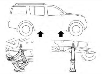
Check suspension warning light (if so equipped)
This light may indicate a malfunction in the auto- leveling suspension. For additional information, refer to “Jacking up vehicle and removing the damaged tire” in the “In case of emergency” section of this manual.
Instruments and controls 2-15
Engine oil pressure low/ Engine coolant temperature high warning light
This light warns of low engine oil pressure or high engine coolant temperature.
If the light flickers or comes on during normal driving, pull off the road in a safe area, stop the engine and allow it to cool. If the light remains on after checking the oil and coolant, stop the en- gine immediately and call a NISSAN dealer or other authorized repair shop. This light is not designed to indicate a low oil or low coolant level. Check the oil level with the dipstick and check the coolant level on the reservoir. See “Engine oil” and “Checking engine coolant level” in the “Maintenance and do-it-yourself” section of this manual. Also see “If your vehicle overheats” in the “In case of emer- gency” section of this manual.
CAUTION
● Running the engine with the engine oil pressure warning light on could cause serious damage to the engine almost immediately. Such damage is not cov- ered by warranty. Turn off the engine as soon as it is safe to do so.
2-16 Instruments and controls
● If the gauge indicates engine coolant temperature over the normal range, stop the vehicle as soon as safely pos- sible. If the engine is overheated, con- tinued operation of the vehicle may se- riously damage the engine. See “If your vehicle overheats” in the “In case of emergency” section for immediate ac- tion required.
4WD warning light
model)
The 4WD warning light comes on when the igni- tion switch is placed in the ON position. It turns off soon after the engine is started.
If the engine or vehicle is not functioning properly, the warning light will either remain illuminated or blink. See “4WD warning light” in the “Starting and driving” section.
CAUTION
● If the warning light comes on or blinks during operation, have your vehicle checked by a NISSAN dealer as soon as possible.
● Do not drive on dry hard surface roads in the 4H or 4LO position. If the 4WD warning light turns on when you are driving on dry hard surface roads: – in the AUTO or 4H position, shift the
4WD shift switch to 2WD.
– in the 4LO position, stop the vehicle, move the shift selector to the N posi- tion and shift the 4WD shift switch to 2WD.
● If the warning light is still on after the above operation, have your vehicle checked by a NISSAN dealer as soon as possible.
Low fuel warning light
This light comes on when the fuel level in the fuel tank is getting low. Refuel as soon as it is conve- nient, preferably before the fuel gauge reaches E (Empty). There will be a small reserve of fuel in the tank when the fuel gauge needle reaches E (Empty).
Low tire pressure warning light
Your vehicle is equipped with a Tire Pressure Monitoring System (TPMS) that monitors the tire pressure of all tires except the spare.
The low tire pressure warning light warns of low tire pressure or indicates that the TPMS is not functioning properly.
After the ignition switch is placed in the ON position, this light illuminates for about 1 second and turns off. Low tire pressure warning:
If the vehicle is being driven with low tire pressure, the warning light will illuminate. A CHECK TIRE PRESSURE warning also appears in the vehicle information display. If you select the tire pressure information in the display (if so equipped), the LOW PRESSURE warning message will be dis- played. The tire pressure for each tire will also be displayed.
When the low tire pressure warning light illuminates, you should stop and adjust the tire pressure of all 4 tires to the recom- mended COLD tire pressure shown on the Tire and Loading Information label located in the driver’s door opening. The low tire pressure warning light does not automati- cally turn off when the tire pressure is ad- justed. After the tire is inflated to the rec- ommended pressure, the vehicle must be driven at speeds above 16 MPH (25 km/h) to activate the TPMS and turn off the low
tire pressure warning light. Use a tire pres- sure gauge to check the tire pressure.
The CHECK TIRE PRESSURE warning is active as long as the low tire pressure warning light remains illuminated.
For additional information, see “Vehicle informa- tion display” in the “Instruments and controls” section and “Tire Pressure Monitoring System (TPMS)” in the “Starting and driving” section and in the “In case of emergency” section. TPMS malfunction:
If the TPMS is not functioning properly, the low tire pressure warning light will flash for approxi- mately 1 minute when the ignition switch is placed in the ON position. The light will remain on after the 1 minute. Have the system checked by a NISSAN dealer. The CHECK TIRE PRESSURE warning does not appear if the low tire pressure warning light illuminates to indicate a TPMS mal- function.
For additional information, see “Tire Pressure Monitoring System (TPMS)” in the “Starting and driving” section and “Tire pressure” in the “Main- tenance and do-it-yourself” section in this manual.
WARNING
● If the light does not illuminate with the ignition switch in the ON position, have the vehicle checked by a NISSAN dealer as soon as possible.
● If the light illuminates while driving, avoid sudden steering maneuvers or abrupt braking, reduce vehicle speed, pull off the road to a safe location and stop the vehicle as soon as possible. Driving with under-inflated tires may permanently damage the tires and in- crease the likelihood of tire failure. Se- rious vehicle damage could occur and may lead to an accident and could re- sult in serious personal injury. Check the tire pressure for all four tires. Adjust the tire pressure to the recommended COLD tire pressure shown on the Tire and Loading Information label located in the driver’s door opening to turn the low tire pressure warning light OFF. If the light still comes on while driving after adjusting the tire pressure, a tire may be flat. If you have a flat tire, re- place it with a spare tire as soon as possible.
Instruments and controls 2-17
● When a spare tire is mounted or a wheel is replaced, tire pressure will not be indicated, the TPMS will not function and the low tire pressure warning light will flash for approximately 1 minute. The light will remain on after 1 minute. Contact your NISSAN dealer as soon as possible for tire replacement and/or system resetting.
● Replacing tires with those not originally specified by NISSAN could affect the proper operation of the TPMS.
CAUTION
● The TPMS is not a substitute for the regular tire pressure check. Be sure to check the tire pressure regularly.
● If the vehicle is being driven at speeds of less than 16 MPH (25 km/h), the TPMS may not operate correctly.
● Be sure to install the specified size of
tires to the 4 wheels correctly.
Master warning light
This light comes on when various vehicle infor- mation display warnings appear.
2-18 Instruments and controls
Seat belt warning light and chime
The light and chime remind you to fasten your seat belts. The light illuminates whenever the ignition switch is placed in the ON or START position and remains illuminated until the driver’s seat belt is fastened. At the same time, the chime sounds for about 6 seconds unless the driver’s seat belt is securely fastened. The seat belt warning light may also illuminate if the front passenger’s seat belt is not fastened when the front passenger’s seat is occupied . For 7 seconds after the ignition switch is placed in the ON position, the system does not activate the warning light for the front passenger. Refer to “Seat belts” in the “Safety—Seats, seat belts and supplemental restraint system” section for precautions on seat belt usage.
Supplemental air bag warning light
When the ignition switch is placed in the ON or START position, the supplemental air bag warn- ing light illuminates for about 7 seconds and then turns off. This means the system is operational.
If any of the following conditions occur, the front air bag, front seat-mounted side-impact air bag , roof-mounted curtain and rollover air bag and pretensioner systems need servicing and your vehicle must be taken to a NISSAN dealer: ● The supplemental air bag warning light re-
mains on after approximately 7 seconds.
● The supplemental air bag warning light
flashes intermittently.
● The supplemental air bag warning light does
not come on at all.
Unless checked and repaired, the supplemental restraint system (air bag system) and/or the pre- tensioners may not function properly. For addi- tional details see “Supplemental restraint sys- tem” in the “Safety—Seats, seat belts and supplemental restraint system” section of this manual.
WARNING
If the supplemental air bag warning light is on, it could mean that the front air bag, side air bag, curtain air bag systems and/or pretensioner systems will not op- erate in an accident. To help avoid injury to yourself or others, have your vehicle checked by a NISSAN dealer as soon as possible.
INDICATOR LIGHTS For additional information on warnings and indi- cators, see “Vehicle information display” later in this section.
Front passenger air bag status light
The front passenger air bag status light ( will be lit and the passenger front air bag will be OFF depending on how the front passenger seat is being used.
For front passenger air bag status light operation, see “Front passenger air bag and status light” in the “Safety — Seats, seat belts and supplemental restraint system” section of this manual. High beam indicator light (blue)
This blue light comes on when the headlight high beams are on and goes out when the low beams are selected.
The high beam indicator light also comes on when the passing signal is activated.
Malfunction Indicator Light (MIL)
If this indicator light comes on steady or blinks while the engine is running, it may indicate a potential emission control malfunction. The Malfunction Indicator Light may also come on steady if the fuel-filler cap is loose or missing, or if the vehicle runs out of fuel. Check to make sure the fuel-filler cap is installed and closed tightly, and that the vehicle has at least 3 gallons (11.4 liters) of fuel in the fuel tank.
light should After a few driving trips, the turn off if no other potential emission control system malfunction exists. If this indicator light comes on steady for 20
seconds and then blinks for 10 seconds when the engine is not running, it indicates that the vehicle is not ready for an emission control sys- tem inspection/maintenance test. See “Readi- ness for inspection/maintenance (I/M) test” in the “Technical and consumer information” section of this manual.Operation
The Malfunction Indicator Light will come on in one of two ways: ● Malfunction Indicator Light on steady — An emission control system malfunction has been detected. Check the fuel-filler cap if the LOOSE FUEL CAP warning appears in the vehicle information display, and the fuel- filler cap is loose or missing, tighten or install the cap and continue to drive the vehicle. light should turn off after a few The driving trips. If the light does not turn off after a few driving trips, have the vehicle inspected by a NISSAN dealer. You do not need to have your vehicle towed to the dealer.
● Malfunction Indicator Light blinking — An engine misfire has been detected which may damage the emission control system. To re- duce or avoid emission control system dam- age: – do not drive at speeds above 45 MPH
(72 km/h).
– avoid hard acceleration or deceleration. – avoid steep uphill grades. – if possible, reduce the amount of cargo
being hauled or towed.
Instruments and controls 2-19
The Malfunction Indicator Light may stop blinking and come on steady. Have the vehicle inspected by a NISSAN dealer. You do not need to have your vehicle towed to the dealer.
CAUTION
Continued vehicle operation without hav- ing the emission control system checked and repaired as necessary could lead to poor driveability, reduced fuel economy, and possible damage to the emission con- trol system.
Security indicator light
This light blinks whenever the ignition switch is in the LOCK, OFF or ACC position. This function indicates the security system equipped on the vehicle is operational.
For additional tems” later in this section.
information, see “Security sys-
Slip indicator light
This indicator will blink when the VDC system or the traction control system is operating, thus alerting that the vehicle is nearing its traction limits. The road surface may be slippery.
2-20 Instruments and controls
Turn signal/hazard indicator lights
The appropriate light flashes when the turn signal switch is activated.
Both lights flash when the hazard switch is turned on.
Vehicle Dynamic Control (VDC) OFF indicator light
This indicator light comes on when the Vehicle Dynamic Control off switch is pushed to OFF, the transfer case is in the 4LO position ( model), or when the Vehicle Dynamic Control system is not functioning properly. This indicates the Vehicle Dynamic Control system is not oper- ating.
Push the Vehicle Dynamic Control OFF switch again or restart the engine and the system will operate normally. See “Vehicle Dynamic Control (VDC) system” in the “Starting and driving” sec- tion of this manual.
The Vehicle Dynamic Control OFF light also comes on when you place the ignition switch in the ON position. The light will turn off after about 2 seconds if the system is operational. If the light stays on or comes on along with the SLIP indica-
tor light while you are driving, have the Vehicle Dynamic Control system checked by a NISSAN dealer. While the Vehicle Dynamic Control system is operating, you might feel slight vibration or hear the system working when starting the vehicle or accelerating, but this is normal. AUDIBLE REMINDERS Brake pad wear warning The disc brake pads have audible wear warnings. When a disc brake pad requires replacement, it makes a high pitched scraping sound when the vehicle is in motion, whether or not the brake pedal is depressed. Have the brakes checked as soon as possible if the warning sound is heard. Key reminder chime A chime sounds if the driver’s door is opened while the key is left in the ignition switch. Remove the key and take it with you when leaving the vehicle. Light reminder chime With the ignition switch placed in the OFF posi- tion, a chime sounds when the driver’s door is opened if the headlights or parking lights are on. Turn the headlight control switch off before leav- ing the vehicle.
VEHICLE INFORMATION DISPLAY
The icons at the bottom of the display screen show the options available:
ENTER — Press the INFO button to select
a highlighted option.
NEXT — Rotate the INFO button to high-
light an option.
WIC1248
The vehicle information display 䊊1 is located to the left of the speedometer. It displays such items as: ● automatic transmission position indicator ● cruise control system information ● Intelligent Key operation information (if soequipped)
● some indicators and warnings ● other information For details about the Intelligent Key, see “NISSAN Intelligent Key™” in the “Pre-driving checks and adjustments” section.
WIC1249
HOW TO USE THE VEHICLE INFORMATION DISPLAY Press the vehicle information display INFO but- ton 䊊1 located on the instrument panel to toggle through the following modes. MPG → Range → Warning Rotate the INFO button 䊊2 to highlight the de- sired menu option within the selected mode. Press the INFO button 䊊1 to enter the high- lighted menu.
Instruments and controls 2-21
WIC1166
Warning mode The warning mode can be selected to view any warnings that may be present. Once the screen is selected you have the option of skipping the warning or viewing it in detail. Warnings can be present for issues such as an open door or low fuel. For more information about potential warnings see “Vehicle information dis- play warnings and indicators” later in this section.
2-22 Instruments and controls
Vehicle information display warnings and indicators 1. Door and liftgate open warning
2. Lock warning (NISSAN Intelligent Key™
model)
3. Low fuel warning
4. Low windshield-washer fluid warning
5. No key warning (NISSAN Intelligent Key™
model)
6. Parking brake warning
LIC2005
7. Shift P warning (NISSAN Intelligent Key™model)
8. Cruise main switch indicator
9. Cruise set switch indicator
Instruments and controls 2-23
10. NISSAN Intelligent Key™ battery discharge indicator (NISSAN Intelligent Key™ model)
11. Transfer 4LO position indicator (
model)
12. 4WD shift indicator (
model)
13. Shift selector position indicator
14. Loose fuel cap warning
15. Check tire pressure waning Door and liftgate open warning
This warning illuminates when a door, the liftgate or the liftgate glass has been opened when the ignition switch is placed in the ON position. Lock warning (NISSAN Intelligent Key™ model) This warning illuminates and a chime sounds if the ignition switch has been in the ACC or ON position and then placed in the OFF position. Place the ignition switch in the LOCK position and the warning and chime will turn off. Refer to “Shift P warning” in this section for additional information. Low fuel warning This warning illuminates when the fuel level in the fuel tank is getting low. Refuel as soon as it is 2-24 Instruments and controls
convenient, preferably before the fuel gauge reaches E (Empty). There will be a small re- serve of fuel in the tank when the fuel gauge needle reaches E (Empty).
Low windshield-washer fluid warning
This warning illuminates when the windshield- washer fluid is at a low level. Add windshield- washer fluid as necessary. See “Windshield- washer fluid” in the “Maintenance and do-it- yourself” section of this manual. No key warning (NISSAN Intelligent Key™ model)
This warning illuminates following two condi- tions:
1. When the ignition switch is pushed and the Intelligent Key cannot be recognized by the system. If this warning illuminates, you can- not start the engine.
Check for the following causes and perform the assigned remedies:
– The battery of the Intelligent Key carried with you is discharged completely. Re- place the battery with a new one.
– The Intelligent Key carried with you is not registered to the system. Use the regis- tered Intelligent Key.
– You do not have an Intelligent Key with
you. Carry an Intelligent Key with you.
2. When the door is closed with the Intelligent Key left outside the vehicle and the ignition switch is in the ACC or ON position. A chime will also sound. Parking brake warning
This warning illuminates when the parking brake is set and the vehicle is driven. SHIFT P warning (NISSAN Intelligent Key™ model)
This warning illuminates when the ignition switch is in the ACC or OFF position and the shift selector is in any position other than (Park) posi- tion. Also, a chime sounds when the ignition switch is in the OFF position.
If this warning illuminates, move the shift selector to the P (Park) position or start the engine.
If the shift selector is moved to the P (Park) position, the lock warning will appear. Refer to “Lock warning” in this section.
For additional information about Intelligent Key, see “NISSAN Intelligent Key™” in the “Pre-driving checks and adjustments” section.
Cruise main switch indicator
This indicator illuminates when the cruise control main switch is pushed. The indicator turns off when the main switch is pushed again. When the cruise main switch indicator the cruise control system is operational. Cruise set switch indicator light
illuminates,
The light comes on while the vehicle speed is controlled by the cruise control system. If the light blinks while the engine is running, it may indicate the cruise control system is not functioning prop- erly. Have the system checked by a NISSAN dealer. NISSAN Intelligent Key™ battery dis- charge indicator (NISSAN Intelligent Key™ model)
This indicator illuminates when the Intelligent Key battery is running out of power. If this indicator illuminates, replace the battery with a new one. See “Battery replacement” in the “Maintenance and do-it-yourself” section. Transfer 4LO position indicator ( model)
This indicator illuminates when the 4WD shift switch is set in the 4LO position with the ignition switch placed in the ON position.
If the 4WD shift switch is set in the 4LO position and the indicator blinks, stop the vehicle, drive slowly forward and the indicator will turn on.
When you shift between 4H and 4LO, stop the vehicle, move the shift selector to the N (Neutral) position, then depress and turn the 4WD shift switch to 4LO or 4H.
The transfer case may be damaged if you shift the switch while driving.
You cannot move the transfer 4WD shift switch between 4H and 4LO unless you have first stopped the vehicle and moved the shift selector to N (Neutral). Make sure the transfer 4LO posi- tion indicator illuminates when you shift the 4WD shift switch to 4LO. The indicator may blink while shifting from one drive mode to the other. 4WD shift indicator (
model)
While the engine is running, the 4WD shift indi- cator will illuminate the position selected by the 4WD shift switch. The 4WD shift indicator may blink while shifting from one drive mode to the other. Automatic transmission position indicator When the ignition switch is placed in the ON position, this indicator shows the shift selector
position. See “Driving the vehicle” in the “Starting and driving” section of this manual. Loose fuel cap warning This warning appears when the fuel-filler cap is not tightened correctly after the vehicle has been refueled. See “Fuel-filler cap” in the “Pre-driving checks and adjustments” section. Check tire pressure warning This warning appears when the low tire pressure warning light in the meter illuminates and low tire pressure is detected. If this warning appears, stop the vehicle and adjust the tire pressure to the recommended COLD tire pressure shown on the Tire and Loading Information label. See “Low tire pressure warning light” earlier in this section and “Tire Pressure Monitoring System (TPMS)” in the “Starting and driving” section.
Instruments and controls 2-25
SECURITY SYSTEMS
LIC0559
Your vehicle has two types of security systems: ● Vehicle security system ● NISSAN Vehicle Immobilizer System VEHICLE SECURITY SYSTEM The vehicle security system provides visual and audible alarm signals if someone opens the doors when the system is armed. It is not, however, a motion detection type system that activates when a vehicle is moved or when a vibration occurs. The system helps deter vehicle theft but cannot prevent it, nor can it prevent the theft of interior or exterior vehicle components in all situations. Al- ways secure your vehicle even if parking for a 2-26 Instruments and controlsbrief period. Never leave your keys in the ignition, and always lock the vehicle when unattended. Be aware of your surroundings, and park in secure, well-lit areas whenever possible.
Many devices offering additional protection, such as component locks, identification markers, and tracking systems, are available at auto supply stores and specialty shops. Your NISSAN dealer may also offer such equipment. Check with your insurance company to see if you may be eligible for discounts for various theft protection features. How to arm the vehicle security system 1. Close all windows. (The system can be armed even if the windows are open.) 2. Place the ignition switch in the LOCK posi-
tion and remove the key.
3. Close all doors. Lock all doors. The doors
can be locked with: ● the power door lock switch (if the door is
opened, locked and then closed).
● the key — master or mechanical (NISSAN
Intelligent Key™ models).
● any request switch (NISSAN Intelligent
Key™ models).
● the keyfob or NISSAN Intelligent Key™.
Keyfob and NISSAN Intelligent Key™ opera- tion:
● Push the
button. All doors lock. The hazard lights flash twice and the horn beeps once to indicate all doors are locked.
● When the
button is pushed with all doors locked, the hazard lights flash twice and the horn beeps once as a re- minder that the doors are already locked.
The horn may or may not beep. Refer to “Silencing the horn beep feature” in the Pre- driving checks and adjustments” section or “Comfort & Convenience settings” in the “Monitor, climate, audio, phone and voice recognition systems” section.
4. Confirm that the
indicator light comes on. The light stays on for about 30
seconds. The vehicle security system is now pre-armed. After about 30 seconds the ve- hicle security system automatically shifts light begins into the armed phase. The to flash once every 3 seconds. If, during the 30-second pre-arm time period, the driver’s door is unlocked by the key, a request switch, the keyfob or Intelligent Key, or if the ignition switch is placed in the ACC or ON position, the system will not arm.● If the key is turned slowly when locking the driver’s door, the system may not arm. Furthermore, if the key is turned beyond the vertical position toward the unlock position to remove the key, the system may be disarmed when the key is removed. If the indicator light fails to glow for 30 seconds, unlock the door once and lock it again.
● Even when the driver and/or passen- gers are in the vehicle, the system will arm with all doors closed and locked with the ignition switch placed in the OFF position.
Vehicle security system activation The vehicle security system will give the following alarm: ● The headlights blink and the horn sounds
intermittently.
● The alarm automatically turns off after ap- proximately 50 seconds. However, the alarm reactivates if the vehicle is tampered with again. The alarm can be shut off by unlocking the driver’s door with the key, a request button on switch or by pressing the the keyfob or Intelligent Key.
The alarm is activated by: ● opening a door without using the key, a request switch, keyfob or Intelligent Key (even if the door is unlocked by using the inside lock knob or the power door lock switch).
How to stop an activated alarm The alarm stops only by unlocking the driver’s door button on the with the key, pressing the keyfob or Intelligent Key, or by unlocking all doors with any request switch (Intelligent Key models). NISSAN VEHICLE IMMOBILIZER SYSTEM The NISSAN Vehicle Immobilizer System will not allow the engine to start without the use of a registered key. If the engine fails to start using a registered key (for example, when interference is caused by another registered key, an automated toll road device or automatic payment device on the key ring), restart the engine using the following procedures: 1. Leave the ignition switch placed in the ON
position for approximately 5 seconds.
2. Place the ignition switch in the OFF or LOCK position and wait approximately 10
seconds.3. Repeat steps 1 and 2. 4. Restart the engine while holding the device (which may have caused the interference) separate from the registered key.
If the no start condition re-occurs, NISSAN rec- ommends placing the registered key on a sepa- rate key ring to avoid interference from other devices. Statement related to Section 15 of FCC Rules for NISSAN Vehicle Immobilizer Sys- tem (CONT ASSY — IMMOBILIZER, ANT ASSY — IMMOBILIZER) This device complies with part 15 of the FCC Rules and RSS-210 of Industry Canada. Operation is subject to the follow- ing two conditions; (1) This device may not cause harmful in- terference, and (2) this device must accept any interference received, including inter- ference that may cause undesired opera- tion of the device. CHANGES OR MODIFICATIONS NOT EX- PRESSLY APPROVED BY THE PARTY RE- SPONSIBLE FOR COMPLIANCE COULD VOID THE USER’S AUTHORITY TO OPER- ATE THE EQUIPMENT.
Instruments and controls 2-27
WINDSHIELD WIPER AND WASHER SWITCH
LIC0474
LIC0965
Security indicator light The security indicator light blinks whenever the ignition switch is placed in the LOCK, OFF or ACC position. This function indicates the NISSAN Ve- hicle Immobilizer System is operational. If the NISSAN Vehicle Immobilizer System is mal- functioning, the light will remain on while the ignition switch is placed in the ON position. If the light still remains on and/or the en- gine will not start, see a NISSAN dealer for NISSAN Vehicle Immobilizer System ser- vice as soon as possible. Please bring all registered keys that you have when visiting your NISSAN dealer for service. 2-28 Instruments and controls
SWITCH OPERATION The windshield wiper and washer operates when the ignition switch is in the ON position.
Push the lever down to operate the wiper at the following speed: 䊊1
Intermittent (INT) — intermittent operation can be adjusted by turning the knob toward 䊊A (Slower) or 䊊B (Faster). Also, the inter- mittent operation speed varies in accor- dance with the vehicle speed. (For example, when the vehicle speed is high, the intermit- tent operation speed will be faster.)
NOTE: You can turn on or turn off the driving speed dependent intermittent wiper func- tion. Refer to “Comfort & convenience set- tings” in the “Monitor, climate, audio, phone and voice recognition systems” sec- tion later in this manual. 䊊2
Low (LO) — continuous low speed operation 䊊3 High (HI) — continuous high speed opera-tion
Push the lever up 䊊4 to have one sweep opera- tion (MIST) of the wiper. Pull the lever toward you 䊊5
to operate the washer. The wiper will also operate several times.WARNING
In freezing temperatures the washer solu- tion may freeze on the windshield and obscure your vision which may lead to an accident. Warm the windshield with the defroster before you wash the windshield.
REAR WINDOW WIPER AND WASHER SWITCH
CAUTION
● Do not operate the washer continu-
ously for more than 30 seconds. ● Do not operate the washer
if
the
windshield-washer reservoir is empty.
● Do not fill the windshield-washer reser- voir with washer fluid concentrates at full strength. So methyl alcohol based windshield-washer fluid concentrates may permanently stain the grille if spilled with filling the windshield- washer fluid reservoir.
● Pre-mix windshield-washer fluid con- centrates with water to the manufactur- er’s recommended levels before pour- ing the fluid into the windshield-washer reservoir. Do not use the windshield- washer reservoir to mix the windshield- washer fluid concentrate and water.
LIC0966
The rear window wiper and washer operate when the ignition switch is placed in the ON position.Turn the switch clockwise from the OFF position to operate the wiper. 䊊1
Intermittent (INT) – intermittent operation (not adjustable)
䊊2 ON – continuous low speed operation Push the switch forward 䊊3
to operate the washer. The wiper will also operate several times.WARNING
In freezing temperatures the washer solu- tion may freeze on the window and ob- scure your vision. Warm the rear window with the defroster before you wash the rear window.
CAUTION
● Do not operate the washer continu-
ously for more than 30 seconds. ● Do not operate the washer
if
fluid reservoir
the is
windshield-washer empty.
● Do not fill the windshield-washer fluid reservoir with washer fluid concen- trates at full strength. Some methyl al- cohol based washer fluid concentrates may permanently stain the grille if spilled while filling the windshield- washer fluid reservoir.
● Pre-mix washer fluid concentrates with water to the manufacturer’s recom- mended levels before pouring the fluid into the windshield-washer fluid reser- voir. Do not use the windshield-washer fluid reservoir to mix the washer fluid concentrate and water.
Instruments and controls 2-29
REAR WINDOW AND OUTSIDE MIRROR (if so equipped) DEFROSTER SWITCH
HEADLIGHT AND TURN SIGNAL SWITCH
LIC1173
To defrost the rear window glass and outside mirrors: Start the engine and push the rear window de- froster switch. The rear window defroster indica- tor light on the display screen comes on. Push the switch again to turn the defroster off. The rear window defroster automatically turns off after approximately 15 minutes.CAUTION
When cleaning the inner side of the rear window, be careful not to scratch or dam- age the rear window defroster.
2-30 Instruments and controls
WIC1250
WIC1186
Type A
HEADLIGHT CONTROL SWITCH Lighting 䊊1 When turning the switch to the
posi- tion, the front parking, tail, license plate and instrument panel lights come on. 䊊2 When turning the switch to the
posi- tion, the headlights come on and all the other lights remain on.
Type B
CAUTION
Use the headlights with the engine run- ning to avoid discharging the vehicle battery.
NOTE: Autolight activation sensitivity and the time delay for autolight shutoff can be ad- justed. See “Comfort & convenience set- tings” in the “Monitor, climate, audio, phone and voice recognition systemsⴖsec- tion later in this manual. To turn on the autolight system: 1. Turn the headlight switch to the AUTO posi-
tion 䊊1 .
2. Turn the ignition switch to ON. 3. The autolight system automatically turns the
headlights on and off.
Initially, if the ignition switch is turned OFF and a door is opened and left open, the headlights remain ON for 5 minutes. If another door is opened during the 5 minutes, then the 5 minute timer is reset. To turn the autolight system off, turn the switch to the OFF,
position.
, or
Instruments and controls 2-31
Type C
SIC3019
WIC1251
Autolight system The autolight system allows the headlights to be set so they turn on and off automatically. The autolight system can: ● Turn on the headlights, front parking, tail, license plate and instrument panel lights au- tomatically when it is dark.
● Turn off all the lights when it is light. ● Keep all the lights on for up to 180 seconds after you place the ignition switch in the OFF position and all doors are closed.
After the headlights automatically turn off with the position, headlight switch in the the headlights will illuminate again for 5 minutes if the headlight switch is moved to the OFF position position. and then turned to the
or
or
LIC0836
Be sure you do not put anything on top of the autolight sensor 䊊1 located in the top side of the instrument panel. The autolight sensor controls the autolight; if it is cov- ered, the autolight sensor reacts as if it is dark out and the headlights will illuminate. If this occurs while parked with the engine off and the ignition switch placed in the ON position, your vehicle’s battery could be- come discharged.2-32 Instruments and controls
WIC1252
Headlight beam select 䊊1 To select the high beam function, push the lever forward. The high beam lights come on and the
light illuminates.
䊊2 Pull the lever back to select the low beam. 䊊3 Pulling and releasing the lever flashes the
headlight high beams on and off.
Battery saver system If the ignition switch is placed in the OFF position while the headlight switch is in the or 5 minutes.
position, the headlights will turn off after
CAUTION
Even though the battery saver feature au- tomatically turns off the headlights after a period of time, you should turn the head- light switch to the OFF position when the engine is not running to avoid discharging the vehicle battery.
DAYTIME RUNNING LIGHT SYSTEM (Canada only) The headlights automatically illuminate at a re- duced intensity when the engine is started with the parking brake released. The daytime running lights operate with the headlight switch in the position. Turn the OFF position or in the position for full headlight switch to the illumination when driving at night.
If the parking brake is applied before the engine is started, the daytime running lights do not illumi- nate. The daytime running lights illuminate when the parking brake is released. The daytime run-
ning lights will remain on until the ignition switch is placed in the OFF position.
WARNING
When the daytime running light system is active, tail lights on your vehicle are not on. It is necessary at dusk to turn on your headlights. Failure to do so could cause an accident injuring yourself and others.
WIC1506
WIC1253
INSTRUMENT BRIGHTNESS CONTROL The instrument brightness control operates when the in or AUTO position (with auto- the lights activated). Turn the control to adjust the brightness of instru- ment panel lights when driving at night.
headlight
control
switch
is
TURN SIGNAL SWITCH Turn signal 䊊1 Move the lever up or down to signal the turning direction. When the turn is com- pleted, the turn signals cancel automatically.
Lane change signal 䊊2 To signal a lane change, move the lever up or down to the point where the indicator light begins to flash, but the lever does not latch.
Instruments and controls 2-33
HAZARD WARNING FLASHER SWITCH
The flashers will operate with the ignition switch placed in any position. Some state laws may prohibit the use of the hazard warning flasher switch while driving.
LIC0394
Push the switch on to warn other drivers when you must stop or park under emergency condi- tions. All turn signal lights flash.WARNING
● If stopping for an emergency, be sure to
move the vehicle well off the road.
● Do not use the hazard warning flashers while moving on the highway unless unusual circumstances force you to drive so slowly that your vehicle might become a hazard to other traffic.
● Turn signals do not work when the haz-
ard warning flasher lights are on.
position.
WIC1254
FOG LIGHT SWITCH (if so equipped) To turn the fog lights on, turn the headlight switch position, then turn the fog light to the switch to the To turn the fog lights on with the headlight switch in the AUTO position, the headlights must be on, then turn the fog light switch to the To turn the fog lights off, turn the fog light switch to the OFF position. The headlights must be on and the low beams selected for the fog lights to operate. The fog lights automatically turn off when the high beam headlights are selected. 2-34 Instruments and controlsposition.
HORN
HEATED SEAT (if so equipped)
LIC0604
To sound the horn, push the center pad area of the steering wheel.WARNING
Do not disassemble the horn. Doing so could affect proper operation of the supplemental front air bag system. Tam- pering with the supplemental front air bag system may result in serious personal injury.
WIC1441
The front seats are warmed by built-in heaters.
1. Start the engine.
2. Push the LO or HI position of the switch, as desired, depending on the temperature. The indicator light in the switch will illuminate.
The heater is controlled by a thermostat, automatically turning the heater on and off. The indicator light will remain on as long as the switch is on.
3. When the seat is warmed or before you leave the vehicle, be sure to turn the switch off.
CAUTION
● Do not use the seat heater for extended periods or when no one is using the seat.
● Do not put anything on the seat which insulates heat, such as a blanket, cush- ion, seat cover, etc. Otherwise, the seat may become overheated.
● Do not place anything hard or heavy on the seat or pierce it with a pin or similar object. This may result in damage to the heater.
● Any liquid spilled on the heated seat should be removed immediately with a dry cloth.
● When cleaning the seat, never use gasoline, benzine, thinner, or any simi- lar materials.
● If any abnormalities are found or the heated seat does not operate, turn the switch off and have the system checked by your NISSAN dealer.
● The battery could run down if the seat heater is operated while the engine is not running.
Instruments and controls 2-35
HEATED STEERING WHEEL (if so equipped)
VEHICLE DYNAMIC CONTROL (VDC) OFF SWITCH
NOTE: The heated steering wheel switch is equipped with a 30 minute timer. After the switch has been activate for 30 minutes, the system will automatically turn off.If the surface temperature of the steering wheel is above 68°F (20°C) when the switch is turned on, the system will not heat the steering wheel. This is not a malfunction.
LIC0421
The heated steering wheel system is designed to operate only when the surface temperature of the steering wheel is below approximately 68°F (20°C).Push the heated steering wheel switch to warm the steering wheel after the engine starts. The indicator light will come on.
If the surface temperature of the steering wheel is below 68°F (20°C), the system will heat the steering wheel to approximately 86°F (30°C), then turn off automatically.
Push the switch again to turn the heated steering wheel off manually. The indicator light will go off.
2-36 Instruments and controls
WIC0534
The vehicle should be driven with the Vehicle Dynamic Control (VDC) system on for most driv- ing conditions. If the vehicle is stuck in mud or snow, the VDC system reduces the engine output to reduce wheel spin. The engine speed will be reduced even if the accelerator is depressed to the floor. If maximum engine power is needed to free a stuck vehicle, turn the VDC system off. To turn off the VDC system, push the VDC OFF switch. The Push the VDC OFF switch again or restart the engine to turn on the system. See “Vehicle Dy- namic Control (VDC) system” in the “Starting and driving” section.indicator will come on.
REAR SONAR SYSTEM OFF SWITCH (if so equipped)
FRONT AND REAR SONAR SYSTEM OFF SWITCH (if so equipped)
The rear sonar system can be disabled by push- ing the OFF switch. When the system is disabled, the indicator light on the switch will illuminate. The system will automatically reset the next time the ignition switch is placed in the ON position. See “Rear sonar system” in the “Starting and driving” section.
LIC0471
WARNING
The rear sonar system is a convenience but it is not a substitute for proper back- ing. Always turn and check that it is safe to do so before backing up. Always back up slowly.
The rear sonar system is active when the ignition switch is placed in the ON position and the shift selector is in R (Reverse).
When sensors detect obstacles within 5.9 ft (1.8
m) of the rear bumper, a beeping tone is emitted.LIC1182
WARNING
● The front sonar system is a convenience but it is not a substitute for proper driving.
● The rear sonar system is a convenience but it is not a substitute for proper back- ing. Always turn and check that it is safe to do so before backing up. Always back up slowly.
Instruments and controls 2-37
The front sonar system: ● is active when the ignition is in the ON position and the shift selector is in a forward gear position.
● a beeping tone is emitted when the sensors detect obstacles within 3 ft (1.0 m) of the front bumper.
The rear sonar system: ● is active when the ignition is in the ON position and the shift selector is in R (Re- verse).
● a beeping tone is emitted when the sensors detect obstacles within 5.9 ft (1.8 m) of the rear bumper.
The front and rear sonar system can be disabled by pushing the OFF switch. When the system is disabled, the indicator light on the switch will illuminate. Push the switch again to enable the system. The indicator light will go off. The system will automatically reset the next time the ignition switch is placed in the ON position. See “Front sonar system” in the “Starting and driving” section.
2-38 Instruments and controls
TOW MODE SWITCH
For additional information, refer to “Tow mode” in the “Technical and consumer information” sec- tion later in this manual.
LIC0594
Tow mode should be used when pulling a heavy trailer or hauling a heavy load. Driving the vehicle in the tow mode with no trailer/load or light trailer/light load will not cause any damage. How- ever, fuel economy may be reduced, and the transmission/engine driving characteristics may feel unusual.Press the tow mode switch to activate tow mode. The indicator light on the tow mode switch illumi- nates when tow mode is selected. Press the tow mode switch again to turn tow mode OFF.
Tow mode is automatically canceled when the ignition switch is placed in the OFF position.
POWER OUTLET
Front row
2nd row
Luggage area
LIC1193
LIC0550
LIC0551
The power outlets are for powering electrical accessories such as cellular telephones.
The power outlets located on the driver’s side of the instrument panel and in the luggage area are powered directly by the vehicle’s battery.
The power outlets located on the passenger’s side of the instrument panel and in the 2nd row are powered only when the ignition switch is in the ACC or ON position.
Open the cap to use a power outlet.
Instruments and controls 2-39
STORAGE
CONSOLE BOX
Center stack storage
INSTRUMENT PANEL STORAGE TRAYS
LIC1183
WARNING
Do not place sharp objects in the trays to help prevent injury in an accident or sud- den stop.
CAUTION
● The outlet and plug may be hot during
or immediately after use.
● Only certain power outlets are designed for use with a cigarette lighter unit. Do not use any other power outlet for an accessory lighter. See your NISSAN dealer for additional information.
● Do not use with accessories that ex- ceed a 12 volt, 120W (10A) power draw. Do not use double adapters or more than one electrical accessory.
● Use power outlets with the engine run- ning to avoid discharging the vehicle battery.
● Avoid using power outlets when the air conditioner, headlights or rear window defroster is on.
● Before inserting or disconnecting a plug, be sure the electrical accessory being used is turned OFF.
● Push the plug in as far as it will go. If good contact is not made, the plug may overheat or the internal temperature fuse may open.
● When not in use, be sure to close the cap. Do not allow water or any other liquids to contact the outlet.
2-40 Instruments and controls
Console box storage trays
LIC1369
LIC1370
LIC1371
Console box storage Pull up on the lever 䊊1 to open the console box lid 䊊2 .
Console box lock Use the master key to lock 䊊1 or unlock 䊊2 the console box.
Instruments and controls 2-41
CAUTION
● Do not use for anything other than
sunglasses.
● Do not leave sunglasses in the sun- glasses holder while parking in direct sunlight. The heat may damage the sunglasses.
LIC1176
WIC0673
GLOVE BOX Open the glove box by pulling the handle. Use the master key when locking 䊊1 or unlocking 䊊2 the glove box.
SUNGLASSES HOLDER To open the sunglasses holder, push and release. Only store one pair of sunglasses in the holder.
WARNING
Keep glove box lid closed while driving to help prevent injury in an accident or a sudden stop.
WARNING
Keep the sunglasses holder closed while driving to prevent an accident.
2-42 Instruments and controls
MAP POCKETS
LIC1195
LIC0575
LIC0568
SEATBACK POCKET The seatback pocket is located on the back of the driver seat. The pocket can be used to store maps.
Small bin OVERHEAD CONSOLE
Instruments and controls 2-43
LIC0569
LIC0570
WIC1507
Medium bin (if so equipped)
Large bin
Storage bins
WARNING
Keep storage bins closed while driving to help prevent injury in an accident or a sudden stop.
Push the button to open a storage bin. Push the lid up to close.
2-44 Instruments and controls
CUP HOLDERS
Front
CAUTION
● Avoid abrupt starting and braking when the cup holder is being used to prevent spilling the drink. If the liquid is hot, it can scald you or your passenger.
● Use only soft cups in the cup holder. Hard objects can injure you in an accident.
Adjustable
2nd row (rear of front console)
LIC1373
LIC0554
LIC0555
2nd row center console (if so equipped)Position the arm on the adjustable cup holder so that the cup is held securely.
To open the 2nd row cup holders (rear of the front console), lower the lid. To close, raise the lid.
Instruments and controls 2-45
LIC0556
LIC0557
WIC1197
2nd row bench (if so equipped)
3rd row
Bottle holder
CAUTION
● Do not use bottle holder for any other objects that could be thrown about in the vehicle and possibly injure people during sudden braking or an accident. ● Do not use bottle holder for open liquid
containers.
2-46 Instruments and controls
To reinstall the 2nd row center console box: 1. Slide the console box over the base toward
the rear of the vehicle.
2. Push down to lock the console box in place. 3. Replace the cup holder tray.
LIC0576
2ND ROW CENTER CONSOLE (if so equipped) Pull up on the lever to open the console box lid.LIC0577
Removing the 2nd row center console box To remove the 2nd row center console box: 䊊1
䊊2 Pull up on the handle to tilt the console boxLift out the cup holder tray.
up.
䊊3 Move the console box toward the front of the
vehicle and lift it out.
Instruments and controls 2-47
LIC0571
LIC2014
CARGO AREA STORAGE BIN To open the cargo area storage bin, pull down on the tab and pull the lid off.
CAUTION
Placing additional items in the area speci- fied for the jack may dent body panel or damage power back door assembly (if so equipped).
LIC0572
To access the floor storage area, push down 䊊1
to raise the handle, then pull up on the handle 䊊2
to lift the luggage board. LUGGAGE HOOKS The luggage hooks can be used to secure cargo with ropes or other types of straps.2-48 Instruments and controls
WARNING
● Properly secure all cargo with ropes or straps to help prevent it from sliding or shifting. Do not place cargo higher than the seatbacks. In a sudden stop or col- lision, unsecured cargo could cause personal injury.
● Use suitable ropes and hooks to secure
cargo.
● Never allow anyone to ride in the lug- gage area. It is extremely dangerous to ride in a cargo area inside of a vehicle. In a collision, people riding in these areas are more likely to be seriously injured or killed.
● Do not allow people to ride in any area of your vehicle that is not equipped with seats and seat belts.
● The child restraint top tether strap may be damaged by contact with items in the cargo area. Secure any items in the cargo area. Your child could be seri- ously injured or killed in a collision if the top tether strap is damaged.
● Be sure everyone in your vehicle is in a
seat and using a seat belt properly.
LTI0089
LTI0090
Side finisher When hooking on ropes, do not apply a load of more than 55 lb (245 N) to a single 䊊A hook or 44
lb (196 N) to a single 䊊B hook.Floor hooks Do not apply a load of more than 110 lb (490 N) to a single hook.
Instruments and controls 2-49
WARNING
● Drive extra carefully when the vehicle is loaded at or near the cargo carrying capacity, especially if the significant portion of that load is carried on the roof rack.
● Heavy loading of the roof rack has the potential to affect the vehicle stability and handling during sudden or abnor- mal handling maneuvers.
● Roof
rack load should be evenly
distributed.
● Do not exceed maximum roof rack load
weight capacity.
● Properly secure all cargo with ropes or straps to help prevent it from sliding or shifting. In a sudden stop or collision, unsecured cargo could cause personal injury.
LIC1177
CAUTION
Use care when placing or removing items from the roof rack. If you cannot comfort- ably lift the items onto the roof rack from the ground, use a ladder or stool.
ROOF RACK
2-50 Instruments and controls
Always distribute the luggage evenly on the roof rack. Do not load more than 200 lbs (91 kg) on entire roof rack. Be sure load is evenly distributed across both crossbars. Be careful that your ve- hicle does not exceed the Gross Vehicle Weight Rating (GVWR) or its Gross Axle Weight Rating (GAWR front and rear). The GVWR and GAWR are located on the F.M.V.S.S. label (located on the driver’s door pillar). For more information regarding GVWR and GAWR, refer to “Vehicle loading information” in the “Technical and con- sumer information” section later in this manual.
WINDOWS
POWER WINDOWS
WARNING
● Make sure that all passengers have their hands, etc. inside the vehicle while it is in motion and before closing the windows. Use the window lock switch to prevent unexpected use of the power windows.
● Do not leave children unattended inside the vehicle. They could unknowingly ac- tivate switches or controls and become trapped in a window. Unattended chil- dren could become involved in serious accidents.
The power windows operate when the ignition switch is placed in the ON position, or for about 45 seconds after the ignition switch is placed in the OFF position. If the driver’s or passenger’s door is opened during this period of about 45
seconds, power to the windows is canceled.Instruments and controls 2-51
LIC1200
The crossbars can be adjusted forward and backward. Loosen the thumbwheel 䊊1 and ad- just the crossbar to the desired position. Tighten the thumbwheel. Place your luggage on the bars and secure the luggage with rope to the utility loops 䊊2 . Do not place luggage on the side rails or tie rope directly to the side rails. Always be sure the thumbwheels are fully tightened to keep the crossbar in place. Do not use utility loops for any purpose other than securing luggage.Driver’s side power window switch The driver’s side control panel is equipped with switches to open or close the front and rear passenger windows. To open a window, push the switch and hold it down. To close a window, pull the switch and hold it up. To stop the opening or closing function at any time, simply release the switch.
WIC1237
Front passenger’s power window switch The passenger’s window switch operates only the corresponding passenger’s window. To open the window, push the switch and hold it down 䊊1 . To close the window, pull the switch up 䊊2 .
LIC1181
1. Window lock button 2. 3. 4. 5. 6.
Power door lock switch Front passenger side automatic switch Right rear passenger window switch Left rear passenger window switch Driver side automatic switch
2-52 Instruments and controls
WIC1255
LIC0410
Rear power window switch The rear power window switches open or close only the corresponding windows. To open the window, push the switch and hold it down 䊊1 . To close the window, pull the switch up 䊊2 . Locking passengers’ windows When the window lock button is depressed, only the driver’s side window can be opened or closed. Push it again to cancel the window lock function.
Automatic operation To fully open a window equipped with automatic operation, press the window switch down (only driver’s side shown) to the second detent and release it; it need not be held. The window auto- matically opens all the way. To stop the window, lift the switch up while the window is opening.
To fully close a window equipped with automatic operation, pull the switch up to the second detent and release it; it need not be held. To stop the window, press the switch down while the window is closing.
Auto-reverse function The auto-reverse function can be activated when a window is closed by automatic operation. Depending on the environment or driving conditions, the auto-reverse function may be activated if an impact or load similar to something being caught in the window oc- curs.
WARNING
There are some small distances immedi- ately before the closed position which cannot be detected. Make sure that all passengers have their hands, etc., inside the vehicle before closing the window.
the dealer
If the vehicle’s battery is disconnected, replaced, or jump started, the power window auto-reverse function may not operate properly. If this occurs, please contact to re-initialize the power window auto-reverse system. If the control unit detects something caught in a window equipped with automatic operation as it is closing, the window will be immediately low- ered.
Instruments and controls 2-53
The power vent windows operate when the igni- tion switch is placed in the ON position, or for about 45 seconds after the ignition switch is placed in the OFF position. If the driver’s or passenger’s door is opened during this 45 sec- ond period, power to the vent windows is can- celled.
LIC1417
POWER VENT WINDOWS (if so equipped) Use the vent window switch located on the driv- er’s side of the instrument panel to open and close the power vent windows. The windows cannot be operated separately. To open the power vent windows press and hold the switch. To close the windows pull up and hold the switch.
2-54 Instruments and controls
LIC0524
MANUAL VENT WINDOWS (if so equipped) To open a manual vent window, pull the latch handle toward you until it releases. To lock the window in the open position, push the latch handle rearward until it locks. To close a manual vent window, pull the latch handle toward you and push the rear portion of the latch toward the rear of the vehicle until it locks.
MOONROOF (if so equipped)
WIC0812
AUTOMATIC MOONROOF The moonroof will only operate when the ignition switch is placed in the ON position. The auto- matic moonroof is operational for about 45 sec- onds, even if the ignition switch is placed in the ACC or OFF position. If the driver’s door or the front passenger’s door is opened during this period of about 45 seconds, power to the moon- roof is canceled. Sliding the moonroof To fully open the moonroof, push the switch to- ward the open position 䊊3 .
To fully close the moonroof, push the switch toward the close position 䊊4 . To open or close the moonroof part way, push the switch in any direction 䊊5 while the moonroof is sliding open or closed to stop it in the desired position. Tilting the moonroof To tilt the moonroof up, push the tilt switch to- ward the up position 䊊1 . When the moonroof is open, it will automatically close and then tilt up.
To tilt the moonroof down, push the tilt switch toward the down position 䊊2 . Restarting the moonroof sliding switch The sliding switch will become inoperable after the battery terminal is disconnected, the electri- cal supply interrupted and/or some abnormality detected. Use the following reset procedure to return moonroof operation to normal.
1.
If the moonroof lid is open, push the tilting switch repeatedly toward the down position 䊊2 to fully close the lid.
2. Push and hold the tilting switch for more than 2 seconds toward the down position 䊊2 to reestablish the lid’s home position. The moonroof should now operate normally.
Auto-reverse function (when closing or tilting down the moonroof) The auto-reverse function can be activated when the moonroof is closed or tilted down by auto- matic operation when the ignition switch is placed in the ON position or for about 45 sec- onds after the ignition switch is placed in the OFF position. Depending on the environment or driving conditions, the auto-reverse function may be activated if an impact or load similar to something being caught in the moonroof occurs.
WARNING
There are some small distances immedi- ately before the closed position which cannot be detected. Make sure that all passengers have their hands, etc., inside the vehicle before closing the moonroof.
When closing:
If the control unit detects something caught in the moonroof as it moves to the front, the moonroof will immediately open backward.
Instruments and controls 2-55
When tilting down:
If the control unit detects something caught in the moonroof as it tilts down, the moonroof will im- mediately tilt up.
If the auto-reverse function malfunctions and re- peats opening or tilting up the moonroof, keep pushing the tilt down switch within 5 seconds after it happens; the moonroof will fully close gradually. Make sure nothing is caught in the moonroof.
WARNING
● In an accident you could be thrown from the vehicle through an open moonroof. Always use seat belts and child restraints.
● Do not allow anyone to stand up or extend any portion of their body out of the moonroof opening while the vehicle is in motion or while the moonroof is closing.
CAUTION
● Remove water drops, snow, ice or sand
from the moonroof before opening.
● Do not place heavy objects on the
moonroof or surrounding area.
2-56 Instruments and controls
INTERIOR LIGHT
Sunshade Open and close the sunshade by sliding it for- ward or backward. If the moonroof does not close Have your NISSAN dealer check and repair the moonroof.
LIC0585
The interior light has a three-position switch and operates regardless of ignition switch position. When the switch is in the ON position 䊊1 , the interior lights illuminate, regardless of door posi- tion. The lights will go off after about 15 minutes unless the ignition switch is in the ON position. When the switch is in the DOOR position 䊊2 , the interior lights and puddle lights (if so equipped) will stay on for about 30 seconds when: ● The doors are unlocked by the keyfob, a key or the power door lock switch while all doors are closed and the ignition switch is in the OFF position.
NOTE: The footwell lights (if so equipped) and door step lights illuminate when the driver and passenger doors are open regardless of the interior light switch position. These lights will turn off automatically after about 15 minutes while doors are open to prevent the battery from becoming discharged.
CAUTION
Do not use for extended periods of time with the engine stopped. This could result in a discharged battery.
● The driver’s door is opened and then closed while the key is removed from the ignition switch.
● The key is removed from the ignition switch
while all doors are closed.
The lights will turn off while the 30 second timer is activated when: ● The driver’s door is locked by the keyfob, a
key, or the power door lock switch.
● The ignition switch is placed in the ON po-
sition.
When the switch is in the OFF position 䊊3 , the interior lights do not illuminate, regardless of door position. The puddle lights (if so equipped) come on when any front or rear passenger door is opened.
The lights will turn off automatically after 15 min- utes while doors are open to prevent the battery from becoming discharged.
LIC0587
CONSOLE LIGHT The console light 䊊1 will turn on whenever the parking lights or headlights are illuminated. The console light brightness can be adjusted with the illumination brightness control.
Instruments and controls 2-57
PERSONAL LIGHTS
MAP LIGHTS
CARGO LIGHT
LIC0588
The personal lights on the overhead console can be swiveled 360 degrees. To turn on the light, press the button. Press the button again to turn off the light.LIC0586
To turn the map lights on, press the switches. To turn them off, press the switches again.CAUTION
Do not use for extended periods of time with the engine stopped. This could result in a discharged battery.
LIC0590
The cargo light on the overhead trim has a three- position switch. To operate, push the switch to the desired position. ON: The light is illuminated. Normal (center) position: The light illuminates when the lift gate or glass hatch is opened. The light turns off when the lift gate or glass hatch is closed. OFF: The light does not illuminate regardless of lift gate position or lock status.2-58 Instruments and controls
HOMELINK姞 UNIVERSAL TRANSCEIVER (if so equipped)
The HomeLink姞 Universal Transceiver provides a convenient way to consolidate the functions of up to three individual hand-held transmitters into one built-in device. HomeLink姞 Universal Transceiver: ● Will operate most Radio Frequency (RF) devices such as garage doors, gates, home and office lighting, entry door locks and se- curity systems.
● Is powered by your vehicle’s battery. No separate batteries are required. If the vehi- cle’s battery is discharged or is discon- nected, HomeLink姞 will retain all program- ming.
Once the HomeLink姞 Universal Transceiver is programmed, retain the original trans- mitter for future programming procedures (Example: new vehicle purchases). Upon sale of the programmed HomeLink姞 Universal Transceiver buttons should be erased for security purposes. For additional information, refer to “Program-