- 2009 Nissan Armada Owners Manuals
- Nissan Armada Owners Manuals
- 2004 Nissan Armada Owners Manuals
- Nissan Armada Owners Manuals
- 2012 Nissan Armada Owners Manuals
- Nissan Armada Owners Manuals
- 2006 Nissan Armada Owners Manuals
- Nissan Armada Owners Manuals
- 2008 Nissan Armada Owners Manuals
- Nissan Armada Owners Manuals
- 2005 Nissan Armada Owners Manuals
- Nissan Armada Owners Manuals
- 2007 Nissan Armada Owners Manuals
- Nissan Armada Owners Manuals
- 2011 Nissan Armada Owners Manuals
- Nissan Armada Owners Manuals
- 2010 Nissan Armada Owners Manuals
- Nissan Armada Owners Manuals
- Download PDF Manual
-
3. The engine oil pressure warning/engine il- coolant temperature high indicator luminates, this may indicate a malfunction. Move the vehicle off the road in a safe area and allow the engine to cool. If after check- remains ing the oil and coolant, the on, do not continue to drive and call a NISSAN dealer.
The check engine light may also come ON. If only it remains on, you do not need to have your vehicle towed, but have it inspected soon by a NISSAN dealer. See “Check engine light” in the “Instruments and controls ” section of this manual.
WARNING
AUTOMATIC TRANSMISSION
Overheating can result in reduced engine power and vehicle speed. The reduced speed may be lower than other traffic, which could increase the chance of a col- lision. Be especially careful when driving. If the vehicle cannot maintain a safe driv- ing speed, pull to the side of the road in a safe area. Allow the engine to cool and return to normal operation. See “If your vehicle overheats” in the “In case of emer- gency” section of this manual.
CAUTION
Running the engine with the engine oil pressure warning light on could cause se- rious damage to the engine almost imme- diately. Such damage is not covered by warranty. Turn off the engine as soon as it is safe to do so.
WARNING
● Do not depress the accelerator pedal while shifting from P (Park) or N (Neu- tral) to R (Reverse), or L (Low). Always depress the brake pedal until shifting is completed. Failure to do so could cause you to lose control and have an accident.
● Cold engine idle speed is high, so use caution when shifting into a forward or reverse gear before the engine has warmed up.
● Never shift to P (Park) or R (Reverse) while the vehicle is moving. This could cause an accident.
CAUTION
● When stopping the vehicle on an uphill grade, do not hold the vehicle by de- pressing the accelerator pedal. The foot brake should be used for this purpose. ● Do not downshift abruptly on slippery roads. This may cause a loss of control.
The automatic transmission in your vehicle is electronically controlled to produce maximum power and smooth operation.
The recommended operating procedures for this transmission are shown on the following pages. Follow these procedures for maximum vehicle performance and driving enjoyment. Starting the vehicle 1. After starting the engine, fully depress the foot brake pedal before moving the shift selector out of the P (Park) position.
2. Keep the foot brake pedal depressed and
move the shift selector into a driving gear.
3. Release the foot brake, then gradually start
the vehicle in motion.
The automatic transmission is designed so the foot brake pedal MUST be depressed before shifting from P (Park) to any drive position while the ignition switch is in the ON position. The shift selector cannot be moved out of the P (Park) position and into any of the other gear positions if the ignition switch is placed in the LOCK or OFF position.
Starting and driving 5-15
WARNING
R (Reverse):
Apply the parking brake if the shift selec- tor is in any position while the engine is not running. Failure to do so could cause the vehicle to move unexpectedly or roll away and result in serious personal injury or property damage.
If the ignition switch is placed in the OFF or ACC position for any reason while the vehicle is in N (Neutral), or any D (Drive) position, the ignition switch cannot be turned to the LOCK position. Move the shift selector to the P (Park) position, then the ignition switch can be turned to LOCK. P (Park):
To move the shift selector:
WSD0187
: Shift while depressing the brake pedal
CAUTION
: Shift without depressing brake pedal
Shifting After starting the engine, fully depress the brake pedal and move the shift selector out of the P (Park) position.
5-16 Starting and driving
To prevent transmission damage, use the P (Park) or R (Reverse) position only when the vehicle is completely stopped.
Use the P (Park) shift selector position when the vehicle is parked or when starting the engine. Make sure the vehicle is completely stopped. The brake pedal should be depressed to move the shift selector from N (Neutral) or any drive position to P (Park). Apply the parking brake. When parking on a hill, apply the parking brake first, then move the shift selector into the P (Park) position.
CAUTION
To prevent transmission damage, use the P (Park) or R (Reverse) position only when the vehicle is completely stopped.
Use the R (Reverse) position to back up. Make sure the vehicle is completely stopped before selecting the R (Reverse) position. The brake pedal must be depressed to move the shift selector from P (Park), N (Neutral) or any drive position to R (Reverse).
N (Neutral):
Neither forward nor reverse gear is engaged. The engine can be started in this position. You may shift to N (Neutral) and restart a stalled engine while the vehicle is moving. D (Drive): Use this position for all normal forward driving. 4 (Fourth gear): Use this position for driving up and down long slopes where engine braking would be advanta- geous. Do not downshift into the 4 position at speeds over the following and do not exceed the follow- ing speeds in the 4 position.
27 MPH (44 km/h) w/tow mode
1 (Low gear): Use this position when climbing steep hills slowly or slow driving through deep snow, sand or mud, or for maximum engine braking on steep downhill grades. Do not downshift into the 1 position at speeds over the following and do not exceed the follow- ing speeds in the 1 position.
2WD and AUTO: 43 MPH (70 km/h) w/o tow mode 37 MPH (60 km/h) w/tow mode 4H: 43 MPH (70 km/h) w/o tow mode 37 MPH (60 km/h) w/tow mode 4LO: 19 MPH (30 km/h) w/o tow mode 16 MPH (27 km/h) w/tow mode
4H:
62 MPH (100 km/h)
4LO:
31 MPH (50 km/h)
3 (Third gear):
Use this position for driving up and down long slopes where engine braking would be advanta- geous. 2 (Second gear):
Use this position for hill climbing or engine brak- ing on downhill grades.
Do not downshift into the 2 position at speeds over the following and do not exceed the follow- ing speeds in the 2 position.
2WD and AUTO:
71 MPH (115 km/h) w/o tow mode
62 MPH (100 km/h) w/tow mode
4H:
62 MPH (100 km/h) w/o tow mode
62 MPH (100 km/h) w/tow mode 4LO: 31 MPH (50 km/h) w/o tow mode
LSD0090
Shift lock release If the battery is discharged, the shift selector may not be moved from the P (Park) position even with the brake pedal depressed. To move the shift selector, release the shift lock. The shift selector can be moved to N (Neutral). However, the steering wheel will be locked un- less the ignition switch is placed in the ON posi- tion (for models with a steering lock mechanism). This allows the vehicle to be moved if the battery is discharged.
Starting and driving 5-17
PARKING BRAKE
WARNING
● Be sure the parking brake is fully re- leased before driving. Failure to do so can cause brake failure and lead to an accident.
● Do not release the parking brake from
outside the vehicle.
● Do not use the shift selector in place of the parking brake. When parking, be sure the parking brake is fully engaged. ● Do not leave children unattended in a vehicle. They could release the parking brake and cause an accident.
Accelerator downshift — in D position — For passing or hill climbing, depress the accel- erator pedal to the floor. This shifts the transmis- sion down into a lower gear, depending on the vehicle speed. Fail-safe When the fail-safe operation occurs, please note that the transmission will be locked in any of the forward gears according to the condition. If the vehicle is driven under extreme con- ditions, such as excessive wheel spinning and subsequent hard braking, the fail-safe system may be activated. This will occur even if all electrical circuits are functioning properly. In this case, turn the ignition switch OFF and wait for 3 seconds. Then turn the ignition switch back to the ON position. The vehicle should return to its normal operating condition. If it does not return to its normal operating condition, have a NISSAN dealer check the transmis- sion and repair it if necessary.
To push the shift lock release, complete the fol- lowing procedure: 1. Place the ignition switch in the LOCK posi-
tion and remove the key. 2. Apply the parking brake. 3. Remove the shift lock release cover as shown. 4. Use a protective cloth on the tip of a small screwdriver before inserting it in the shift lock release slot and pushing down.
5. Move the shift selector to the N (Neutral) position while holding down the shift lock release.
6. Place the ignition switch in the ON position to unlock the steering wheel (for models with a steering lock mechanism).
7. Now the vehicle may be moved to the de-
sired location.
If the shift selector cannot be moved out of P (Park), have a NISSAN dealer check the auto- matic transmission system as soon as possible.
WARNING
If the shift selector cannot be moved from the P (Park) position while the engine is running and the brake pedal is depressed, the stop lights may not work. Malfunction- ing stop lights could cause an accident injuring yourself and others.
5-18 Starting and driving
CRUISE CONTROL
● If the SET indicator light blinks, push the cruise control ON·OFF switch off and have the system checked by a NISSAN dealer.
● The SET indicator light may blink when the cruise control ON·OFF switch is pushed ON while ACCEL/RES, COAST/SET, or CANCEL switch. To prop- erly set the cruise control system, use the following procedures.
pushing
the
LSD0158
To engage: Firmly depress the parking brake. To release: 1. Firmly apply the foot brake. 2. Move the shift selector to the P (Park) posi-tion.
3. Firmly depress the parking brake pedal and it
will release.
4. Before driving, be sure the brake warning
light goes out.
LSD0159
1. ACCEL/RES switch 2. COAST/SET switch 3. CANCEL switch 4. ON·OFF switch PRECAUTIONS ON CRUISE CONTROL ● If the cruise control system malfunctions, it cancels automatically. The SET indicator light in the vehicle information display then blinks to warn the driver, see “Vehicle infor- mation display” in the “Instruments and con- trols” section.
WARNING
Do not use the cruise control when driving under the following conditions: ● When it is not possible to keep the
vehicle at a set speed.
● In heavy traffic or in traffic that varies in
speed.
● On winding or hilly roads. ● On slippery roads (rain, snow, ice, etc.). ● In very windy areas. Doing so could cause a loss of vehicle control and result in an accident.
Starting and driving 5-19
To reset at a slower cruising speed, use one of the following three methods. ● Lightly tap the brake pedal. When the ve- hicle attains the desired speed, push the COAST/SET switch and release it.
● Push and hold the COAST/SET switch. Re- lease the switch when the vehicle slows to the desired speed.
● Push and release the COAST/SET switch. Each time you do this, the set speed de- creases by about 1 MPH (1.6 km/h).
To resume the preset speed, push and re- lease the ACCEL/RES switch. The vehicle re- turns to the last set cruising speed when the vehicle speed is over 25 MPH (40 km/h).
CRUISE CONTROL OPERATIONS The cruise control allows driving at a speed be- tween 25 - 89 MPH (40 - 144 km/h) without keeping your foot on the accelerator pedal. To turn on the cruise control, push the ON·OFF switch on. The CRUISE indicator light in the vehicle information display will illuminate. To set cruising speed, accelerate the vehicle to the desired speed, push the COAST/SET switch and release it. The SET indicator light in the vehicle information display will illuminate. Take your foot off the accelerator pedal. Your vehicle maintains the set speed. ● To pass another vehicle, depress the ac- celerator pedal. When you release the pedal, the vehicle returns to the previously set speed.
● The vehicle may not maintain the set speed when going up or down steep hills. If this happens, drive without the cruise control.
To cancel the preset speed, use one of the following three methods. ● Push the CANCEL button; the SET indicator light in the vehicle information display goes out.
● Tap the brake pedal; the SET indicator light
goes out.
5-20 Starting and driving
● Push the ON·OFF switch off. Both the CRUISE indicator light and SET indicator light in the vehicle information display go out. The cruise control is automatically canceled and the SET light in the vehicle information display goes out if: ● you depress the brake pedal while pushing the ACCEL/RES or SET/COAST switch. The preset speed is deleted from memory. ● the vehicle slows down more than 8 MPH
(13 km/h) below the set speed.
● you move the shift selector to N (Neutral). To reset at a faster cruising speed, use one of the following three methods. ● Depress the accelerator pedal. When the vehicle attains the desired speed, push and release the COAST/SET switch.
● Push and hold the ACCEL/RES switch. When the vehicle attains the speed you de- sire, release the switch.
● Push and release the ACCEL/RES switch. Each time you do this, the set speed in- creases by about 1 MPH (1.6 km/h).
BREAK-IN SCHEDULE
INCREASING FUEL ECONOMY
CAUTION
During the first 1,200 miles (2,000 km), follow these recommendations to obtain maximum engine performance and en- sure the future reliability and economy of your new vehicle. Failure to follow these recommendations may result in short- ened engine life and reduced engine performance.
● Avoid driving for long periods at constant speed, either fast or slow, and do not run the engine over 4,000 rpm.
● Do not accelerate at full throttle in any gear. ● Avoid quick starts. ● Avoid hard braking as much as possible. ● Do not tow a trailer for the first 500 miles (800 km). Your engine, axle or other parts could be damaged.
● Accelerate slowly and smoothly. Maintain cruising speeds with a constant accelerator position.
● When cruising at highway speeds, it is more economical to use the air conditioner and leave the windows closed to reduce drag.
● For vehicles equipped with
, use 4H or 4L position only when necessary. Four- wheel drive operation lowers fuel economy.
● Drive at moderate speeds on the highway. Driving at high speed lowers fuel economy. ● Avoid unnecessary stopping and braking. Maintain a safe distance behind other ve- hicles.
● Use a proper gear range which suits road conditions. On level roads, shift into high gear as soon as possible.
● Avoid unnecessary engine idling. ● Keep your engine tuned up. ● Follow the recommended periodic mainte-
nance schedule.
● Keep the tires inflated to the correct pres- sure. Low tire pressure increases tire wear and lowers fuel economy.
● Keep the front wheels in correct alignment. Improper alignment increases tire wear and lowers fuel economy.
● Air
conditioner operation
fuel economy. Use the air conditioner only when necessary.
lowers
Starting and driving 5-21
TRANSFER CASE SHIFTING PROCEDURES All mode 4WD system provides 4 positions (AUTO, 2WD, 4H and 4LO), so you can select the desired drive mode according to the driving conditions.
USING FOUR WHEEL DRIVE
(4WD)
WARNING
CAUTION
to raise two wheels off
● For 4WD equipped vehicles, do not at- tempt the ground and shift the transmission to any drive or reverse position with the engine running. Doing so may result in drivetrain damage or unexpected ve- hicle movement which could result in serious vehicle damage or personal injury.
● Do not attempt to test a 4WD equipped vehicle on a 2-wheel dynamometer (such as the dynamometers used by some states, provinces or territories for emissions testing), or similar equip- ment even if the other two wheels are raised off the ground. Make sure you inform test facility personnel that your vehicle is equipped with 4WD before it is placed on a dynamometer. Using the wrong test equipment may result in drivetrain damage or unexpected ve- hicle movement which could result in serious vehicle damage or personal injury.
● Do not drive the vehicle in the 4H or 4LO position on dry hard surface roads. Driv- ing on dry, hard surfaces in 4H or 4LO may cause unnecessary noise, tire wear and increased fuel consumption. If the 4WD warning light turns on when you are driving on dry hard surface roads: – in the 4H position, shift the 4WD shift
switch to 2WD.
– in the 4LO position, stop the vehicle, move the shift selector to the N posi- tion with the brake pedal depressed, and shift the 4WD shift switch to 2WD.
● If the warning light is still on after the above operation, have your vehicle checked by a NISSAN dealer as soon as possible.
● The transfer case may be damaged if you continue driving with the warning light blinking.
5-22 Starting and driving
2WD or 4WD shift procedure:
4WD Shift
Switch Position
Wheels Driven
Indicator Light
4WD shift
Transfer 4LO position
Use Conditions
4WD Shift Procedure
AUTO
2WD
4H
Rear wheels or 4 wheels
Rear wheels
4 wheels
Neutral
4LO
4 wheels
For driving on paved or slippery roads
For driving on dry, paved roads (Economy drive)
For driving on rocky, sandy or snow- covered roads
Neutral disengages the automatic trans- mission mechanical parking lock, which will allow the vehicle to roll. Do not leave the transfer shift position in Neutral.*2
For use when maximum power and trac- tion is required (for example: on steep grades or rocky, sandy, muddy roads)
*1
May blinkIlluminated
Move the 4WD switch. 2WD <—> AUTO <—> 4H 4WD shift indicator light will indicate transfer shift position engaged. IT IS NOT NECESSARY TO MOVE THE SHIFT SELECTOR TO THE N POSITION IN THIS OP- ERATION. PERFORM THIS OPERATION WHEN DRIVING STRAIGHT.
1. Stop the vehicle. 2. Move the shift selector to the N position. 3. Push the 4WD shift switch and move it to 4LO
or 4H with the brake pedal depressed.
YOU CANNOT MOVE THE TRANSFER 4WD SHIFT SWITCH BETWEEN 4H AND 4LO (OR 4LO TO 4H) UNLESS YOU HAVE FIRST STOPPED THE VEHICLE, DEPRESSED THE BRAKE PEDAL AND MOVED THE SHIFT SELEC- TOR TO NEUTRAL. *3
*1: The transfer 4LO position indicator light may blink. Stop the vehicle. Be sure to shift the 4WD shift switch after the shift selector has been moved to the N position. If the indicator light keeps blinking after the 4WD shift procedure in the previous page, drive slowly without abrupt maneuvers for a while. Then the light will turn on or off. (cid:129) Avoid making a turn or abrupt starts while shifting to 4LO. Otherwise gears may grind, damaging the drive system.
*2: While changing in and out of 4LO, the ignition switch must be ON and the vehicle’s engine must be running for a shift to take place and for the indicator
lights (4WD shift and 4LO position indicator) to be operable. Otherwise, the shift will not take place and no indicator lights will be on or flashing.
*3: Make sure the transfer 4LO position indicator light turns on when you shift the 4WD shift switch to 4LO. The
4LO is selected. See “Vehicle Dynamic Control (VDC) system” later in this section.
indicator light will also turn on when
Starting and driving 5-23
The transfer case 4WD shift switch is used to select either 2WD or 4WD depending on the driving conditions. There are four types of drive modes available, AUTO, 2WD, 4H and 4LO. The 4WD shift switch electronically controls the transfer case operation. Rotate the switch to move between each mode, 2WD, AUTO, 4H and 4LO. You must push the switch in to select 4LO, and the vehicle MUST be stationary and the shift selector in the N position when chang- ing into or out of 4LO.
WARNING
When parking, apply the parking brake before stopping the engine and make sure that the 4WD shift indicator light is on and the ATP warning light goes off. Otherwise, the vehicle could unexpectedly move even if the automatic transmission is in the P position.
CAUTION
● Never shift the 4WD shift switch be-
tween 4LO and 4H while driving.
● The 4H position provides greater trac- tion. Avoid excessive speed, as it will cause increased fuel consumption and higher oil temperatures, and could damage components, drivetrain Speeds over 62 MPH (100 km/h) in 4H is not recommended.
● The 4LO position provides maximum power and traction. Avoid raising ve- hicle speed excessively, as the maxi- mum speed is approximately 31 MPH (50 km/h).
● When driving straight, shift the 4WD shift switch to the 2WD, AUTO or 4H position. Do not move the 4WD shift switch when making a turn or reversing. ● Do not shift the 4WD shift switch (be- tween 2WD, AUTO and 4H) while driving on steep downhill grades. Use the en- gine brake and low automatic transmis- sion gears (D1 or D2) for engine braking.
● Do not operate the 4WD shift switch (between 2WD, AUTO and 4H) with the rear wheels spinning.
● Do not drive on dry hard surface roads in the 4H or 4LO position. Driving on dry hard surfaces in 4H or 4LO may cause unnecessary noise and tire wear. NISSAN recommends driving in the 2WD or AUTO position under these conditions.
● The 4WD transfer case may not be shifted between 4H and 4LO at low am- bient temperatures and the transfer 4LO position indicator light may blink even when the 4WD shift switch is shifted. After driving for a while you can change the 4WD transfer case between 4H and 4LO.
When driving on rough roads, ● Set the 4WD shift switch to AUTO, 4H or
4LO.
● Drive carefully according to the road surface
conditions.
5-24 Starting and driving
When the vehicle is stuck, ● Set the 4WD shift switch to 4H or 4LO. ● If it is difficult to free the vehicle, repeat to in-
forward and backward movement crease the movement.
● If the vehicle is stuck deep in mud, place stones or wooden blocks under the tires. Then try the recovery procedures above. Tire chains may be effective.
CAUTION
● Do not spin the tires excessively. Tires will sink deep into the mud, making it difficult to free the vehicle.
● Avoid shifting gears with the engine running at high speeds as this may cause malfunction.
● If the 4WD shift switch is operated while making a turn, accelerating or decelerating or if the ignition switch is turned off while in the AUTO, 4H or 4LO, you may feel a jolt. This is not abnormal.
● When the vehicle is stopped after mak- ing a turn, you may feel a slight jolt after the shift selector is shifted to N or P. This occurs because the transfer clutch is released and not because of a malfunction.
LSD0144
CAUTION
4WD shift switch operations ● Shift the 4WD shift switch to either the 2WD, AUTO, 4H or 4LO position, depend- ing on driving conditions.
● With the switch set to the AUTO position, distribution of torque to the front and rear wheels changes automatically, depending on road conditions encountered [ratio; 0 : 100 (2WD) → 50 : 50 (4WD)]. This results in improved driving stability.
● When driving straight, shift the 4WD shift switch to the 2WD, AUTO or 4H position. Do not move the 4WD shift switch when making a turn or reversing. ● Do not shift the 4WD shift switch while driving on steep downhill grades. Use the engine brake and low automatic transmission gears (D1 or D2) for en- gine braking.
● Do not operate the 4WD shift switch
with the rear wheels spinning.
Starting and driving 5-25
● Before placing the 4WD shift switch in the 4H position from 2WD or AUTO, ensure the vehicle speed is less than 62
MPH (100 km/h). Failure to do so can damage the 4WD system.● Never shift the 4WD shift switch be-
tween 4LO and 4H while driving.
● Engine idling speed is high while warm- ing up the engine. Be especially careful when starting or driving on slippery sur- faces with the 4WD shift switch set in AUTO.
● The 4WD shift indicator light may blink while shifting from one drive mode to the other. When the shifting is com- pleted, the 4WD shift indicator light will come on. If the indicator light does not come on immediately, make sure the area around the vehicle is safe, and drive the vehicle straight, accelerate or decelerate or move the vehicle in re- verse, then shift the 4WD shift switch. ● If the 4WD warning light comes on, the
4WD indicator light goes out.
LSD0147
CAUTION
4WD shift indicator light The 4WD shift indicator light is located in the vehicle information display.
The light should turn off within 1 second after turning the ignition switch to the ON position.
While the engine is running, the 4WD shift indi- cator light will illuminate the position selected by the 4WD shift switch.
● When the 4WD shift switch is turned to the AUTO position at low ambient tem- peratures, the 4WD shift indicator light may show 4H. If this happens, all four wheels are driven as torque distribution is in the 4H position. Be careful as the vehicle may become difficult to turn. When the vehicle is driven, the 4WD shift indicator light should change to AUTO.
5-26 Starting and driving
● If the 4WD shift indicator light indica- tion changes to 2WD when the 4WD shift switch is shifted to the AUTO or 4H position at low ambient temperatures, the 2WD mode may be being engaged due to malfunctioning drive system. If the indicator does not return to normal and the 4WD warning light comes on, have the system checked by the nearest NISSAN dealer.
4WD warning light
Warning light
Comes on or blinks
when:
Comes on
Blinks rap- idly
Blinks slowly
There is a mal- function in the 4–wheel drive
system
The transfer case oil tem- perature is ab- normally high
The difference in wheel rota- tion is large
The 4WD warning light is located in the meter.
The 4WD warning light comes on when the igni- tion switch is turned to ON. It turns off soon after the engine is started.
If any malfunction occurs in the 4WD system when the ignition switch is ON, the warning light will either remain illuminated or blink.
If the 4WD warning light comes on, the 4WD shift indicator light goes out.
High-temperature transfer case oil makes the warning light blink rapidly (about twice per sec- ond). If the warning light blinks rapidly during operation, stop the vehicle in a safe place imme- diately. Then if the light goes off after a while, you can continue driving.
A large difference between the diameters of front and rear wheels will make the warning light blink slowly (about once per two seconds). Change the 4WD shift switch into 2WD and do not drive fast.
CAUTION
● If the warning light comes on or blinks slowly during operation or rapidly after stopping the vehicle for a while, have your vehicle checked by a NISSAN dealer as soon as possible.
● Shifting between 4H and 4LO is not recommended when the 4WD warning light turns on.
● When the warning light comes on, the 2WD mode may be engaged even if the 4WD shift switch is in AUTO or 4H. Be especially careful when driving. If corre- sponding parts are malfunctioning, the 4WD mode will not be engaged even if the 4WD shift switch is shifted.
● Do not drive the vehicle in the 4H or 4LO position on dry hard surface roads. Driv- ing on dry, hard surfaces in 4H or 4LO may cause unnecessary noise, tire wear and increased fuel consumption. If the 4WD warning light turns on when you are driving on dry hard surface roads: – in the AUTO or 4H position, shift the
4WD shift switch to 2WD.
– in the 4LO position, stop the vehicle, move the shift selector to the N posi- tion with the brake pedal depressed, and shift the 4WD shift switch to 2WD.
Starting and driving 5-27
PARKING/PARKING ON HILLS
● If the warning light is still on after the above operation, have your vehicle checked by a NISSAN dealer as soon as possible.
● The transfer case may be damaged if you continue driving with the warning light blinking.
WARNING
● Do not stop or park the vehicle over flammable materials such as dry grass, waste paper or rags. They may ignite and cause a fire.
● Safe parking procedures require that both the parking brake be set and the transmission placed into P (Park). Fail- ure to do so could cause the vehicle to move unexpectedly or roll away and re- sult in an accident. Make sure the shift selector has been pushed as far forward as it can go and cannot be moved without depressing the foot brake pedal.
WSD0050
● Never leave the engine running while
the vehicle is unattended.
● Do not leave children unattended inside the vehicle. They could unknowingly ac- tivate switches or controls. Unattended children could become involved in seri- ous accidents.
1. Firmly apply the parking brake.
2. Move the shift selector to the P (Park) posi-
tion.
3. To help prevent the vehicle from rolling into traffic when parked on an incline, it is a good practice to turn the wheels as illustrated.
5-28 Starting and driving
POWER STEERING
BRAKE SYSTEM
● HEADED DOWNHILL WITH CURB: 䊊A
Turn the wheels into the curb and move the vehicle forward until the curb side wheel gently touches the curb.
● HEADED UPHILL WITH CURB: 䊊B
Turn the wheels away from the curb and move the vehicle back until the curb side wheel gently touches the curb.
● HEADED UPHILL OR DOWNHILL, NO
CURB: 䊊C Turn the wheels toward the side of the road so the vehicle will move away from the cen- ter of the road if it moves.
4. Place the ignition switch in the LOCK posi-
tion.
The power assisted steering uses a hydraulic pump, driven by the engine, to assist steering. If the engine stops or the drive belt breaks, you will still have control of the vehicle. However, much greater steering effort is needed, especially in sharp turns and at low speeds.
WARNING
If the engine is not running or is turned off while driving, the power assist for the steering will not work. Steering will be harder to operate.
The brake system has two separate hydraulic circuits. If one circuit malfunctions, you will still have braking at 2 wheels. BRAKE PRECAUTIONS Vacuum assisted brakes The brake booster aids braking by using engine vacuum. If the engine stops, you can stop the vehicle by depressing the brake pedal. However, greater foot pressure on the brake pedal will be required to stop the vehicle and stopping dis- tance will be longer. Using the brakes Avoid resting your foot on the brake pedal while driving. This will overheat the brakes, wear out the brake pads faster, and reduce gas mileage.
To help reduce brake wear and to prevent the brakes from overheating, reduce speed and downshift to a lower gear before going down a slope or long grade. Overheated brakes may reduce braking performance and could result in loss of vehicle control.
Starting and driving 5-29
WARNING
● While driving on a slippery surface, be careful when braking, accelerating or downshifting. Abrupt braking or accel- erating could cause the wheels to skid and result in an accident.
● If the engine is not running or is turned off while driving, the power assist for the brakes will not work. Braking will be harder.
Wet brakes When the vehicle is washed or driven through water, the brakes may get wet. As a result, your braking distance will be longer and the vehicle may pull to one side during braking.
To dry the brakes, drive the vehicle at a safe speed while lightly pressing the brake pedal to heat up the brakes. Do this until the brakes return to normal. Avoid driving the vehicle at high speeds until the brakes function correctly. Parking brake break-in Break-in the parking brake shoes whenever the stopping effect of the parking brake is weakened or whenever the parking brake shoes and/or drum/rotors are replaced, in order to assure the best brake performance. 5-30 Starting and driving
This procedure is described in the vehicle service manual and can be performed by a NISSAN dealer. ANTI-LOCK BRAKING SYSTEM (ABS)
WARNING
● The Anti-lock Braking System (ABS) is a sophisticated device, but it cannot pre- vent accidents resulting from careless or dangerous driving techniques. It can help maintain vehicle control during braking on slippery surfaces. Remem- ber that stopping distances on slippery surfaces will be longer than on normal surfaces even with ABS. Stopping dis- tances may also be longer on rough, gravel or snow covered roads, or if you are using tire chains. Always maintain a safe distance from the vehicle in front of you. Ultimately, the driver is respon- sible for safety.
● Tire type and condition may also affect
braking effectiveness. – When replacing tires,
the specified size of tires on all four wheels.
install
– When installing a spare tire, make sure that it is the proper size and type as specified on the Tire and Loading Information label. See “Tire and Loading Information label” in the “Technical and consumer informa- tion” section of this manual.
– For
detailed
information,
see “Wheels and tires” in the “Mainte- nance and do-it-yourself” section of this manual.
The Anti-lock Braking System (ABS) controls the brakes so the wheels do not lock during hard braking or when braking on slippery surfaces. The system detects the rotation speed at each wheel and varies the brake fluid pressure to pre- vent each wheel from locking and sliding. By preventing each wheel from locking, the system helps the driver maintain steering control and helps to minimize swerving and spinning on slip- pery surfaces. Using the system Depress the brake pedal and hold it down. De- press the brake pedal with firm steady pressure, but do not pump the brakes. The ABS will oper- ate to prevent the wheels from locking up. Steer the vehicle to avoid obstacles.
WARNING
Do not pump the brake pedal. Doing so may stopping distances.
increased
result
in
Normal operation The ABS operates at speeds above 3 - 6 MPH (5
- 10 km/h). The speed varies according to road conditions.When the ABS senses that 1 or more wheels are close to locking up, the actuator rapidly applies and releases hydraulic pressure. This action is similar to pumping the brakes very quickly. You may feel a pulsation in the brake pedal and hear a noise from under the hood or feel a vibration from the actuator when it is operating. This is normal and indicates that the ABS is operating properly. However, the pulsation may indicate that road conditions are hazardous and extra care is re- quired while driving. Self-test feature The ABS includes electronic sensors, electric pumps, hydraulic solenoids and a computer. The computer has a built-in diagnostic feature that tests the system each time you start the engine and move the vehicle at a low speed in forward or reverse. When the self-test occurs, you may hear a “clunk” noise and/or feel a pulsation in the brake
pedal. This is normal and does not indicate a malfunction. If the computer senses a malfunc- tion, it switches the ABS off and illuminates the ABS warning light on the instrument panel. The brake system then operates normally, but without anti-lock assistance. If the ABS warning light illuminates during the self-test or while driving, have the vehicle checked by a NISSAN dealer.
VEHICLE DYNAMIC CONTROL (VDC) SYSTEM
The Vehicle Dynamic Control (VDC) system uses various sensors to monitor driver inputs and ve- hicle motion. Under certain driving conditions, the VDC System helps to perform the following functions: ● Controls brake pressure to reduce wheel slip on one slipping drive wheel so power is transferred to a non slipping drive wheel on the same axle.
● Controls brake pressure and engine output to reduce drive wheel slip based on vehicle speed (traction control function).
● If the 4WD transfer case is shifted into 4LO indicator light will come on and the the VDC system will be turned off. See “Us- ing Four Wheel Drive (4WD)” earlier in this section.
● Controls brake pressure at individual wheels and engine output to help the driver maintain control of the vehicle in the following condi- tions:
– understeer (vehicle tends to not follow the steered path despite increased steer- ing input)
– oversteer (vehicle tends to spin due to
certain road or driving conditions)
Starting and driving 5-31
The VDC system can help the driver to maintain control of the vehicle, but it can not prevent loss of vehicle control in all driving situations. When the VDC system operates, the SLIP indi- cator in the instrument panel flashes so note the following: ● The road may be slippery or the system may determine some action is required to help keep the vehicle on the steered path.
● You may feel a pulsation in the brake pedal and hear a noise or vibration from under the hood. This is normal and indicates that the VDC system is working properly.
● Adjust your speed and driving to the road
conditions.
See “Slip indicator light” and ”Vehicle Dynamic Control (VDC) OFF indicator light” in the ”Instru- ments and controls” section. If a malfunction occurs in the system, the SLIP indicator lights come on in the instru- and ment panel. The VDC system automatically turns off when these indicator lights are on.
The VDC OFF switch is used to turn off the VDC indicator illuminates to indi- system. The cate the VDC system is off.
5-32 Starting and driving
When the VDC switch is used to turn off the system, the VDC system still operates to prevent one drive wheel from slipping by transferring power to a non slipping drive wheel. The SLIP indicator flashes if this occurs. All other VDC functions are off and the SLIP indicator will not flash.
The VDC system is automatically reset to on when the ignition switch is placed in the off position then back to the on position.
The computer has a built in diagnostic feature that tests the system each time you start the engine and move the vehicle forward or in reverse at a slow speed. When the self-test occurs, you may hear a clunk noise and/or feel a pulsation in the brake pedal. This is normal and is not an indication of a malfunction.
WARNING
● The VDC system is designed to help the driver maintain stability but does not prevent accidents due to abrupt steer- ing operation at high speeds or by care- less or dangerous driving techniques. Reduce vehicle speed and be especially careful when driving and cornering on slippery surfaces and always drive carefully.
● Do not modify the vehicle’s suspension. If suspension parts such as shock ab- sorbers, struts, springs, stabilizer bars, bushings and wheels are not NISSAN recommended for your vehicle or are extremely deteriorated, the VDC system may not operate properly. This could adversely affect vehicle handling per- formance, and the SLIP indicator may indica- flash or both the SLIP and tor lights may illuminate.
● If brake related parts such as brake pads, rotors and calipers are not NISSAN recommended or are extremely deteriorated, the VDC system my not operate properly and both the SLIP and may the illuminate.
indicator
lights
● If engine control related parts are not NISSAN recommended or are extremely deteriorated, both the SLIP and indicator lights may illuminate.
● When driving on extremely inclined sur- faces such as higher banked corners, the VDC system may not operate prop- erly and the SLIP indicator may flash or indicator lights both the SLIP and may illuminate. Do not drive on these types of roads.
● When driving on an unstable surface such as a turntable, ferry, elevator or ramp, the SLIP indicator may flash or indicator lights both the SLIP and may illuminate. This is not a malfunc- tion. Restart the engine after driving onto a stable surface.
● If wheels or tires other than the NISSAN recommended ones are used, the VDC system may not operate properly and the SLIP indicator may flash or both the lights may SLIP and illuminate.
indicator
● The VDC system is not a substitute for winter tires or tire chains on a snow covered road.
REAR SONAR SYSTEM
LSD0095
WARNING
● Always turn and look back before back- ing up. The RSS is not a substitute for proper backing procedures.
● Read and understand the limitations of the rear sonar system as contained in this section. Inclement weather may af- fect the function of the RSS; this may include reduced performance or a false activation.
● This system is not designed to prevent
contact with small or moving objects.
● The system is designed as an aid to the driver in detecting large stationary ob- jects to help avoid damaging the ve- hicle. The system will not detect small objects below the bumper, and may not detect objects close to the bumper or on the ground.
● If your vehicle sustains damage to the rear bumper leaving it mis- aligned or bent, the sensing zone may be altered causing inaccurate measure- ment of obstacles or false alarms.
fascia,
The Rear Sonar System (RSS) sounds a tone to warn the driver of obstacles near the rear bumper when the shift selector is in R (Reverse). The system may not detect objects at speeds above 3
mph (5 km/h) and may not detect certain angular or moving objects.The RSS detects obstacles up to 3 ft (1.0 m) from the rear bumper with a decreased coverage area at the outer corners of the bumper, (refer to the illustration for approximate zone coverage areas). As you move closer to the obstacle, the rate of the tone increases. When the obstacle is less than 12 in (30.0 cm) away, the tone will sound continuously. If the RSS detects a station- ary or receding object further than 12 in (30.0
cm) from the side of the vehicle, the tone willStarting and driving 5-33
sound for only 3 seconds. Once the system de- tects an object approaching, the tone will sound again. The RSS automatically turns on when the shift selector is placed in R (Reverse) and the ignition switch is ON. The front and rear sonar system off switch on the instrument panel allows the driver to turn the RSS on and off. To turn the RSS off, the ignition switch must be ON, and the shift selector in R (Reverse). An indicator light on the switch will illuminate when the system is turned off. If the indicator light illuminates when the RSS is not turned off, it may indicate a malfunction in the RSS. Keep the RSS sensors (located on the rear bumper fascia) free from snow, ice and large accumulations of dirt (do not clean the sensors with sharp objects). If the sensors are covered, it will affect the accuracy of the RSS.
5-34 Starting and driving
FRONT SONAR SYSTEM (if so equipped)
LSD0202
WARNING
● Always look around before proceeding. The FSS is not a substitute for proper driving procedures.
● Read and understand the limitations of the front sonar system as contained in this section. Inclement weather may af- fect the function of the FSS, this may include reduced performance or a false activation.
● This system is not designed to prevent
contact with small or moving objects.
● The system is designed as an aid to the driver in detecting large stationary ob- jects to help avoid damaging the ve- hicle. The system will not detect small objects below the bumper, and may not detect objects close to the bumper or on the ground.
● If your vehicle sustains damage to the front bumper fascia, leaving it mis- aligned or bent, the sensing zone may be altered causing inaccurate measure- ment of obstacles or false alarms.
The Front Sonar System (FSS) sounds a tone to warn the driver of obstacles near the front bumper when the shift selector is in a forward gear. The system may not detect objects at speeds above 3 mph (5 km/h) and may not detect certain angular or moving objects.
The FSS detects obstacles up to 3 ft (1.0 m) from the front bumper with a decreased coverage area at the outer corners of the bumper, (refer to the illustration for approximate zone coverage areas). As you move closer to the obstacle, the rate of the tone increases. When the obstacle is less than 12 in (30.0 cm) away, the tone will sound con- tinuously. If the FSS detects a stationary or re- ceding object further than 12 in (30.0 cm) from the side of the vehicle, the tone will sound for only
3 seconds. Once the system detects an object approaching, the tone will sound again. The FSS automatically turns on when the shift selector is placed in a forward gear and the ignition switch is ON. The front and rear sonar system off switch on the instrument panel allows the driver to turn the FSS on and off. To turn the FSS off, the ignition switch must be ON, and the shift selector in D (Drive). An indicator light on the switch will illuminate when the system is turned off. If the indicator light illuminates when the FSS is not turned off, it may indicate a malfunction in the FSS. Keep the FSS sensors (located on the front bumper fascia) free from snow, ice and large accumulations of dirt (do not clean the sensors with sharp objects). If the sensors are covered, it will affect the accuracy of the FSS.
COLD WEATHER DRIVING
FREEING A FROZEN DOOR LOCK To prevent a door lock from freezing, apply de- icer through the key hole. If the lock becomes frozen, heat the key before inserting it into the key hole, or use the remote keyless entry keyfob (if so equipped) or the NISSAN Intelligent Key™ (if so equipped). ANTI-FREEZE In the winter when it is anticipated that the tem- perature will drop below 32°F (0°C), check the anti-freeze to assure proper winter protection. For details, see “Engine cooling system” in the “Maintenance and do-it-yourself” section of this manual. BATTERY If the battery is not fully charged during extremely cold weather conditions, the battery fluid may freeze and damage the battery. To maintain maxi- mum efficiency, the battery should be checked regularly. For details, see “Battery” in the “Main- tenance and do-it-yourself” section of this manual.
DRAINING OF COOLANT WATER If the vehicle is to be left outside without anti- freeze, drain the cooling system, including the engine block. Refill before operating the vehicle. For details, see “Changing engine coolant” in the “Maintenance and do-it-yourself” section of this manual. TIRE EQUIPMENT 1. SUMMER tires have a tread designed to provide superior performance on dry pave- ment. However, the performance of these tires will be substantially reduced in snowy and icy conditions. If you operate your ve- hicle on snowy or icy roads, NISSAN recom- mends the use of MUD & SNOW or ALL SEASON TIRES on all four wheels. Please consult a NISSAN dealer for the tire type, size, speed rating and availability informa- tion.
2. For additional traction on icy roads, studded tires may be used. However, some U.S. states and Canadian provinces prohibit their use. Check local, state and provincial laws before installing studded tires.
Skid and traction capabilities of studded snow tires on wet or dry surfaces may be poorer than that of non-studded snow tires. Starting and driving 5-35
3. Tire chains may be used. For details see “Tire chains” in the “Maintenance and do-it- yourself” section of this manual.
SPECIAL WINTER EQUIPMENT It is recommended that the following items be carried in the vehicle during winter: ● A scraper and stiff-bristled brush to remove ice and snow from the windows and wiper blades.
● A sturdy, flat board to be placed under the
jack to give it firm support.
● A shovel to dig the vehicle out of snowdrifts. ● Extra washer fluid to refill the windshield-
washer fluid reservoir.
DRIVING ON SNOW OR ICE
WARNING
● Wet ice (32°F, 0°C and freezing rain), very cold snow or ice can be slick and very hard to drive on. The vehicle will have much less traction or “grip” under these conditions. Try to avoid driving on wet the road is salted or sanded.
ice until
5-36 Starting and driving
● Whatever the condition, drive with cau- tion. Accelerate and slow down with care. If accelerating or downshifting too fast, the drive wheels will lose even more traction.
● Allow more stopping distance under these conditions. Braking should be started sooner than on dry pavement.
● Allow greater following distances on
slippery roads.
● Watch for slippery spots (glare ice). These may appear on an otherwise clear road in shaded areas. If a patch of ice is seen ahead, brake before reach- ing it. Try not to brake while on the ice, and avoid steering maneuvers.
sudden
any
● Do not use the cruise control on slip-
pery roads.
● Snow can trap dangerous exhaust gases under your vehicle. Keep snow clear of the exhaust pipe and from around your vehicle.
ENGINE BLOCK HEATER (if so equipped)
WARNING
● Do not use your engine block heater with an ungrounded electrical system or a 2-pronged adapter. You can be se- riously injured by an electrical shock if you use an ungrounded connection.
● Disconnect and properly store the en- gine block heater cord before starting the engine. Damage to the cord could result in an electrical shock and can cause serious injury.
● Use a heavy-duty 3-wire, 3-pronged ex- tension cord rated for at least 10 A. Plug the extension cord into a Ground Fault Interrupt (GFI) protected, grounded 110-VAC outlet. Failure to use the proper extension cord or a grounded outlet can result in a fire or electrical shock and cause serious personal injury.
Engine block heaters are available through NISSAN dealers to assist in cold temperature starting. The engine block heater should be used when the outside temperature is 20° F (-7° C) or lower.
To use the engine block heater: 1. Turn the engine off. 2. Open the hood and unwrap the engine block
heater cord.
3. Plug the engine block heater cord into a grounded 3-wire, 3-pronged extension cord.
4. Plug the extension cord into a Ground Fault Interrupt (GFI) protected, grounded 110- volt AC (VAC) outlet.
5. The engine block heater must be plugged in for at least 2 - 4hours, depending on outside temperatures, to properly warm the engine coolant. Use an appropriate timer to turn the engine block heater on.
6. Before starting the engine, unplug and prop- erly store the cord to keep it away from moving parts.
Starting and driving 5-37
MEMO
5-38 Starting and driving
6 In case of emergency
Flat tire . . . . . . . . . . . . . . . . . . . . . . . . . . . . . . . . . . . . . . . . . . . 6-2
Tire Pressure Monitoring System (TPMS). . . . . . . . . . 6-2
Changing a flat tire . . . . . . . . . . . . . . . . . . . . . . . . . . . . . 6-2
Jump starting . . . . . . . . . . . . . . . . . . . . . . . . . . . . . . . . . . . . . 6-8
Push starting. . . . . . . . . . . . . . . . . . . . . . . . . . . . . . . . . . . . . 6-10If your vehicle overheats . . . . . . . . . . . . . . . . . . . . . . . . . . . 6-10
Towing your vehicle . . . . . . . . . . . . . . . . . . . . . . . . . . . . . . . 6-11
Towing recommended by NISSAN . . . . . . . . . . . . . . 6-12
Vehicle recovery (freeing a stuck vehicle) . . . . . . . . . 6-13FLAT TIRE
TIRE PRESSURE MONITORING SYSTEM (TPMS) This vehicle is equipped with the Tire Pressure Monitoring System (TPMS). It monitors tire pres- sure of all tires except the spare. When the low tire pressure warning light is lit, and the CHECK TIRE PRESSURE warning appears in the vehicle information display, one or more of your tires is significantly under-inflated. If equipped, the sys- tem also displays pressure of all tires (except the spare tire) on the display screen by sending a signal from a sensor that is installed in each wheel. If the vehicle is being driven with low tire pressure, the TPMS will activate and warn you of it by the low tire pressure warning light. This system will activate only when the vehicle is driven at speeds above 16 MPH (25 km/h). For more details, refer to “Warning/indicator lights and audible reminders” in the “Instruments and controls” section, “Tire pressure information” in the “Monitor, climate, audio, phone and voice recognition systems” section and “Tire Pressure Monitoring System (TPMS)” in the “Starting and driving” section.
6-2 In case of emergency
WARNING
● If the low tire pressure warning light illuminates while driving, avoid sudden steering maneuvers or abrupt braking, reduce vehicle speed, pull off the road to a safe location and stop the vehicle as soon as possible. Driving with under- inflated tires may permanently damage the tires and increase the likelihood of tire failure. Serious vehicle damage could occur and may lead to an acci- dent and could result in serious per- sonal injury. Check the tire pressure for all four tires. Adjust the tire pressure to the recommended COLD tire pressure shown on the Tire and Loading Informa- tion label to turn the low tire pressure warning light OFF. If you have a flat tire, replace it with a spare tire as soon as possible.
● When a spare tire is mounted or a wheel is replaced, tire pressure will not be indicated, the TPMS will not function and the low tire pressure warning light will flash for approximately 1 minute. The light will remain on after 1 minute. Contact your NISSAN dealer as soon as possible for tire replacement and/or system resetting.
● Replacing tires with those not originally specified by NISSAN could affect the proper operation of the TPMS.
● Do not inject any tire liquid or aerosol tire sealant into the tires, as this may cause a malfunction of the tire pressure sensors.
CHANGING A FLAT TIRE If you have a flat tire, follow the instructions be- low: Stopping the vehicle 1. Safely move the vehicle off the road and
away from traffic.
2. Turn on the hazard warning flashers.
3. Park on a level surface and apply the parking
brake. Move the shift selector to P (Park).
4. Turn off the engine.
5. Raise the hood to warn other traffic and to signal professional road assistance person- nel that you need assistance.
6. Have all passengers get out of the vehicle and stand in a safe place, away from traffic and clear of the vehicle.
WARNING
● Make sure the parking brake is securely applied and the automatic transmission is shifted into P (Park).
● Never change tires when the vehicle is on a slope, ice or slippery areas. This is hazardous.
● Never change tires if oncoming traffic is close to your vehicle. Wait for profes- sional road assistance.
WCE0044
LCE0158
Blocking wheels Place suitable blocks 䊊1 at both the front and back of the wheel diagonally opposite the flat tire 䊊2 to prevent the vehicle from moving when it is jacked up.
Getting the spare tire and tools 1. Lift the luggage board in the cargo area and remove the jack tool kit 䊊A from the storage area. See “Cargo area storage bin” in the “Instruments and controls” section.
WARNING
Be sure to block the wheel as the vehicle may move and result in personal injury.
2. Remove the cargo area storage bin cover. See “Cargo area storage bin” in the “Instru- ments and controls” section.
In case of emergency 6-3
WCE0192
3. Unscrew the rotating mechanism 䊊A coun- terclockwise until loosened on cradle. Re- move the jack.LCE0084
4. Assemble the two straight pieces of the jack rod. Find the oval-shaped opening above the middle of the license plate. Pass the T-shaped end of the jack rod through the opening and direct it toward the spare tire winch, located directly above the spare tire.CAUTION
Do not insert the jack rod straight as it is designed to be inserted at an angle as shown.
LCE0085
5. Fit the square end of the jack rod into the square hole of the wheel nut wrench to form a handle.6. Seat the T-shaped end of the jack rod into the T-shaped opening of the tire winch. Ap- ply pressure to keep the jack rod engaged in the spare tire winch and turn the jack rod counterclockwise to lower the spare tire.
7. Once the spare tire is completely lowered, reach under the vehicle, remove the retainer chain, and carefully slide the tire from under the rear of the vehicle.
6-4 In case of emergency
CAUTION
Be sure to center the spare tire suspend- ing plate on the wheel and then lift the spare tire.
Jacking up vehicle and removing the damaged tire
WARNING
● Never get under the vehicle while it is supported only by the jack. If it is nec- essary to work under the vehicle, sup- port it with safety stands.
● Use only the jack provided with your vehicle to lift the vehicle. Do not use the jack provided with your vehicle on other vehicles. The jack is designed for lifting only your vehicle during a tire change. ● Use the correct jack-up points. Never use any other part of the vehicle for jack support.
● Never jack up the vehicle more than
necessary.
● Never use blocks on or under the jack.
● Do not start or run the engine while vehicle is on the jack. It may cause the vehicle to move. This is especially true for slip differentials.
vehicles
limited
with
● Do not allow passengers to stay in the
vehicle while it is on the jack.
● Never run the engine with a wheel(s) off the ground. It may cause the vehicle to move.
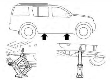
Always refer to the illustration for the correct placement and jack-up points for your specific vehicle model and jack type. Carefully read the caution label attached to the jack body and the following instruc- tions.
1. Loosen each wheel nut one or two turns by turning counterclockwise with the wheel nut wrench. Do not remove the wheel nuts until the tire is off the ground.
NOTE: Before jacking up the vehicle, make sure the ignition switch is placed in the OFF position. If the vehicle is lifted up with the ignition switch placed in the ON position the auto-leveling suspension will become disabled after 60 seconds. To reset the auto-leveling suspension, cycle the igni- tion switch ON/OFF one time.
In case of emergency 6-5
2. Place the jack directly under the jack-up point as illustrated so the top of the jack contacts the vehicle at the jack-up point. The jack-up points are indicated by stamped ar- rows on the side of the frame.
6-6 In case of emergency
WCE0139
The jack should be used on firm and level ground.3.
LCE0087
Install the assembled jack rod into the jack as shown.4. To lift the vehicle, securely hold the jack lever and rod. Carefully raise the vehicle until the tire clears the ground.
5. Remove the wheel nuts and then remove the
tire.
4. Lower
the vehicle slowly until
the tire touches the ground. Then, with the wheel nut wrench, tighten the wheel nuts securely in the sequence illustrated. Lower the ve- hicle completely.
WARNING ● Incorrect wheel nuts or
improperly tightened wheel nuts can cause the wheel to become loose or come off. This could cause an accident.
● Do not use oil or grease on the wheel studs or nuts. This could cause the nuts to become loose.
● Retighten the wheel nuts when the ve- hicle has been driven for 600 miles (1,000 km) (also in cases of a flat tire, etc.).
As soon as possible, tighten the wheel nuts to the specified torque with a torque wrench.
Wheel nut tightening torque:
WCE0063
Installing the spare tire The spare tire is designed for emergency use. See specific instructions under the heading “Wheels and tires” in the “Mainte- nance and do-it-yourself” section of this manual.
1. Clean any mud or dirt from the surface be-
tween the wheel and hub.
2. Carefully put the spare tire on and tighten
98 ft-lb (133 N·m)
the wheel nuts finger tight.
3. With the wheel nut wrench, tighten wheel nuts alternately and evenly as illustrated until they are tight.
The wheel nuts must be kept tightened to specification at all is recom- mended that wheel nuts be tightened to specifications at each lubrication interval.
times.
It
Adjust tire pressure to the COLD pressure. COLD pressure: After vehicle has been parked for three hours or more or driven less than 1 mile (1.6 km). COLD tire pressures are shown on the Tire and Loading Information label affixed to the driver side center pillar. After adjusting tire pressure to the COLD tire pressure, the display (if so equipped) of the tire pressure information may show higher pressure than the COLD tire pres- sure after the vehicle has been driven more than 1 mile (1.6 km). This is because the tire pressure increases as the tire temperature rises. This does not indicate a system mal- function. 5. Securely store the flat tire and jacking equip-
ment in the vehicle.
In case of emergency 6-7
JUMP STARTING
To start your engine with a booster battery, the instructions and precautions below must be fol- lowed. If the battery of a vehicle equipped with the NISSAN Intelligent Key ™ is discharged, the ignition switch cannot be moved from the LOCK position, even when using the me- chanical key or the valet key. Connect the jumper cables to another vehicle, as in the case of a discharged battery, and then the ignition switch can be moved from the LOCK position. Then, jump start the ve- hicle.
WARNING
● If done incorrectly, jump starting can lead to a battery explosion, resulting in severe injury or death. It could also damage your vehicle.
● Explosive hydrogen gas is always present in the vicinity of the battery. Keep all sparks and flames away from the battery.
● Do not allow battery fluid to come into contact with eyes, skin, clothing or painted surfaces. Battery fluid is a cor- rosive sulfuric acid solution which can cause severe burns. If the fluid should come into contact with anything, imme- diately flush the contacted area with water.
● Keep battery out of
children.
the reach of
● The booster battery must be rated at 12
volts. Use of an improperly rated battery can damage your vehicle.● Whenever working on or near a battery, always wear suitable eye protectors (for example, goggles or industrial safety spectacles) and remove rings, metal bands, or any other jewelry. Do not lean over the battery when jump starting.
● Do not attempt to jump start a frozen battery. It could explode and cause se- rious injury.
● Your vehicle has an automatic engine cooling fan. It could come on at any time. Keep hands and other objects away from it.
WARNING
● Always make sure that the spare tire and jacking equipment are properly se- cured after use. Such items can become dangerous projectiles in an accident or sudden stop.
● The spare tire is designed for emer- gency use. See specific instructions un- der the heading “Wheels and tires” in the “Maintenance and do-it-yourself” section of this manual.
6-8 In case of emergency
WARNING
Always follow the instructions below. Failure to do so could result in damage to the charging system and cause personal injury.
1.
If the booster battery is in another vehicle, position the two vehicles to bring their bat- teries near each other. Do not allow the two vehicles to touch.
2. Apply the parking brake. Move the shift se- lector to P (Park). Switch off all unnecessary electrical systems (lights, heater, air condi- tioner, etc.).
WCE0054
3. Remove the vent caps on the battery (if so equipped). Cover the battery with an old cloth to reduce explosion hazard.4. Connect the jumper cables in the sequence
illustrated (䊊A , 䊊B , 䊊C , 䊊D ).
CAUTION
● Always connect positive (⫹) to positive (⫹) and negative (⫺) to body ground (for example, strut mounting bolt, engine lift bracket, etc.) — not to the battery.
● Make sure the jumper cables do not touch moving parts in the engine com- partment and that the cable clamps do not contact any other metal.
5. Start the engine of the booster vehicle and
let it run for a few minutes.
6. Keep the engine speed of the booster ve- hicle at about 2,000 rpm and start the en- gine of the vehicle being jump started.
CAUTION
Do not keep the starter motor engaged for more than 10 seconds. If the engine does not start right away, place the ignition switch in the OFF position and wait 3 to 4
seconds before trying again.7. After starting the engine, carefully discon- nect the negative cable and then the positive cable.
8. Replace the vent caps (if so equipped). Be sure to dispose of the cloth used to cover the vent holes as it may be contaminated with corrosive acid.
In case of emergency 6-9
PUSH STARTING
IF YOUR VEHICLE OVERHEATS
WARNING
WARNING
Do not push start this vehicle. The three- way catalyst may be damaged.
CAUTION
Automatic transmission models cannot be push-started or tow-started. Attempt- ing to do so may cause transmission damage.
6-10 In case of emergency
● Do not continue to drive if your vehicle overheats. Doing so could cause engine damage or a vehicle fire.
● To avoid the danger of being scalded, never remove the radiator or coolant reservoir cap while the engine is still hot. When the radiator or coolant reser- voir cap is removed, pressurized hot water will spurt out, possibly causing serious injury.
● Do not open the hood if steam is com-
ing out.
If your vehicle is overheating (indicated by an extremely high temperature gauge reading and the illumination of the engine oil pressure/engine coolant temperature high indicator light), or if you feel a lack of engine power, detect abnormal noise, etc. take the following steps. 1. Move the vehicle safely off the road, apply the parking brake and move the shift selector to P (Park). Do not stop the engine.
2. Turn off the air conditioner. Open all the windows, move the heater or air conditioner temperature control to maximum hot and fan control to high speed.
3. Get out of the vehicle. Look and listen for steam or coolant escaping from the radiator before opening the hood. (If steam or cool- ant is escaping, turn off the engine.) Do not open the hood further until no steam or coolant can be seen.
4. Open the engine hood.
WARNING
If steam or water is coming from the en- gine, stand clear to prevent getting burned.
5. Visually check drive belts for damage or looseness. Also check if the cooling fan is running. The radiator hoses and radiator should not leak water. If coolant is leaking, the water pump belt is missing or loose, or the cooling fan does not run, stop the en- gine.
WARNING
Be careful not to allow your hands, hair, jewelry or clothing to come into contact with, or get caught in, engine belts or the engine cooling fan. The engine cooling fan can start at any time.
6. After the engine cools down, check the cool- ant level in the engine coolant reservoir tank with the engine running. Add coolant to the engine coolant reservoir tank if necessary. Have your vehicle repaired at a NISSAN dealer.
TOWING YOUR VEHICLE
When towing your vehicle, all State (Provincial in Canada) and local regulations for towing must be followed. Incorrect towing equipment could dam- age your vehicle. Towing instructions are avail- able from a NISSAN dealer. Local service opera- tors are generally familiar with the applicable laws and procedures for towing. To assure proper towing and to prevent accidental damage to your vehicle, NISSAN recommends having a service operator tow your vehicle. It is advisable to have the service operator carefully read the following precautions:
WARNING
● Never ride in a vehicle that is being
towed.
● Never get under your vehicle after it has
been lifted by a tow truck.
CAUTION
● When towing, make sure that the trans- mission, axles, steering system and powertrain are in working condition. If