- 2006 Nissan 350z Owners Manuals
- Nissan 350z Owners Manuals
- 2005 Nissan 350z Owners Manuals
- Nissan 350z Owners Manuals
- 2004 Nissan 350z Owners Manuals
- Nissan 350z Owners Manuals
- 2007 Nissan 350z Owners Manuals
- Nissan 350z Owners Manuals
- 2003 Nissan 350z Owners Manuals
- Nissan 350z Owners Manuals
- 2008 Nissan 350z Owners Manuals
- Nissan 350z Owners Manuals
- Download PDF Manual
-
only when the ignition switch is in the ON or START position. After turning the ignition key to the ON position, the supplemental air bag warning light illuminates. The supplemental air bag Safety — Seats, seat belts and supplemental restraint system 1-35
墌 06.10.24/Z33-D/V5.0 墍
warning light will turn off after about 7
seconds if the system is operational.Failure to follow all instructions in this manual concerning the use of seats, seat belts and child restraints can in- crease the risk or severity of injury in an accident.
Status light:
The front passenger air bag status light is located on the overhead console. The light op- erates as follows: 쐌 Unoccupied passenger seat: The
is OFF and the front passenger air bag is OFF and will not inflate in a crash.
쐌 Passenger seat occupied by a small adult, child or child restraint as outlined in this section: The illuminates to indicate that the front passenger air bag is OFF and will not inflate in a crash.
쐌 Occupied passenger seat and the passenger meets the conditions outlined in this section: The is OFF to indicate that the front passenger air bag is operational.
Front passenger air bag: The front passenger air bag is designed to automatically turn OFF when the vehicle is op- erated under some conditions as described
Front passenger air bag status light
SSS0681
Front passenger air bag and status light
WARNING
The front passenger air bag is designed to automatically turn OFF under some conditions. Read this section carefully to learn how it operates. Proper use of the seat, seat belt and child restraints is necessary for most effective protection.
1-36 Safety — Seats, seat belts and supplemental restraint system
墌 06.10.24/Z33-D/V5.0 墍
below in accordance with U.S. regulations. If the front passenger air bag is OFF, it will not inflate in a crash. The driver air bag and other air bags in your vehicle are not part of this system.
The purpose of the regulation is to help reduce the risk of injury or death from an inflating air bag to certain front passenger seat occupants, such as children, by requiring the air bag to be automatically turned OFF.
The occupant classification sensor (pattern sen- sor) is in the front passenger seat cushion and is designed to detect an occupant and objects on the seat. For example, if a child is in the front passenger seat, the advanced air bag system is designed to turn the passenger air bag OFF in accordance with the regulations. Also, if a child restraint of the type specified in the regulations is on the seat, the occupant classification sensor can detect it and cause the air bag to turn OFF. Front passenger seat adult occupants who are properly seated and using the seat belt as outlined in this manual should not cause the passenger air bag to be automatically turned OFF. For small adults it may be turned OFF, however, if the occupant does not sit in the seat properly (for example, by not sitting upright, by sitting on an edge of the seat, or by otherwise being out of position), this could cause the sensor to turn the air bag OFF. Always be sure to
be seated and wearing the seat belt properly for the most effective protection by the seat belt and supplemental air bag.
passenger seat is unoccupied.
is in the seat but
the If an adult occupant passenger air bag status light is illuminated (indicating that the air bag is OFF), it could be that the person is a small adult, or is not sitting on the seat properly.
The occupant classification sensor is designed to operate as described above to turn the front passenger air bag OFF for specified child re- straints as required by the regulations. Failing to properly secure child restrains and to use the automatic locking mode (child restraint mode) may allow the restraint to tip or move in an accident or sudden stop. This can also result in the passenger air bag inflating in a crash instead of being OFF. See “Child restraints” earlier in this section for proper use and installation.
If a child restraint must be used in the front seat, the passenger air bag status light may or may not be illuminated, depending on the size of the child and the type of child restraint being used. If the air bag status light is not illuminated (indicating that the air bag might inflate in a crash), it could be that the child restraint or seat belt is not being used properly. Make sure that the child restraint is installed properly, the seat belt is used prop- erly and the occupant is positioned properly. If the air bag status light is still not illuminated, try a different child restraint. If the passenger air bag status light will not illuminate even though you believe that the child restraint, the seat belts and the occupant are properly positioned, the system may be sensing an unoccupied seat (in which case the air bag is OFF). A NISSAN dealer can check that the system is OFF by using a special tool. However, until you have confirmed with your dealer that your air bag is working properly, do not transport a child in this vehicle. The air bag system and passenger air bag status Safety — Seats, seat belts and supplemental restraint system 1-37
If the front passenger seat is not occupied, the passenger air bag is designed not to inflate in a crash. However, heavy objects placed on the seat could result in air bag inflation, because of the object being detected by the occupant classification sensor. Other conditions could also result in air bag inflation, such as if a child is standing on the seat, or if two children are on the seat, contrary to the instructions in this manual. Always be sure that you and all vehicle occu- pants are seated and restrained properly. Using the passenger air bag status light, you can monitor when the front passenger air bag is automatically turned OFF with the seat occu- pied. The light will not illuminate when the front
墌 06.10.24/Z33-D/V5.0 墍
light will take a few seconds to register a change in the passenger seat status. However, if the seat becomes unoccupied, the air bag status light will remain off.
If a malfunction occurs in the front passenger air bag system, the supplemental air bag warning located in the meter and gauges light area, will blink. Have the system checked by a NISSAN dealer. Other supplemental front air bag precautions
WARNING
쐌 Do not place any objects on the steering wheel pad or on the instru- ment panel. Also, do not place any objects between any occupant and the steering wheel or instrument panel. Such objects may become dangerous projectiles and cause in- jury if the supplemental front air bag inflates.
쐌 Do not place objects with sharp edges on the seat. Also, do not place heavy objects on the seat that will
leave permanent impressions in the seat. Such objects can damage the seat or occupant classification sen- sor (pattern sensor). This can affect the operation of the air bag system and result in serious personal injury. 쐌 Do not use water or acidic cleaners (hot steam cleaners) on the seat. This can damage the seat or occupant classification sensor. This can also affect the operation of the air bag system and result in serious personal injury.
쐌 Immediately after inflation, several front air bag system components will be hot. Do not touch them; you may severely burn yourself.
쐌 No unauthorized changes should be made to any components or wiring of the supplemental air bag system. This is to prevent accidental inflation of the supplemental air bag or dam- age to the supplemental air bag system.
쐌 Do not make unauthorized changes to your vehicle’s electrical system, suspension system or front end structure. This could affect proper operation of the supplemental front air bag system.
쐌 Tampering with the supplemental front air bag system may result in serious personal injury. Tampering includes changes to the steering wheel and the instrument panel as- sembly by placing material over the steering wheel pad and above the instrument panel or by installing ad- ditional trim material around the air bag system.
쐌 Modifying or tampering with the front passenger seat may result in serious personal injury. For example, do not change the front seats by placing material on the seat cushion or by installing additional trim material, such as seat covers, on the seat that are not specifically designed to as- sure proper air bag operation. Addi-
1-38 Safety — Seats, seat belts and supplemental restraint system
墌 06.10.24/Z33-D/V5.0 墍
tionally, do not stow any objects un- der the front passenger seat or the seat cushion and seatback. Such ob- jects may interfere with the proper operation of the occupant classifica- tion sensor.
쐌 No unauthorized changes should be made to any components or wiring of the seat belt system. This may affect the supplemental front air bag sys- tem. Tampering with the seat belt system may result in serious per- sonal injury.
쐌 Work on and around the supplemen- tal front air bag system should be done by a NISSAN dealer. Installa- tion of electrical equipment should also be done by a NISSAN dealer. The Supplemental Restraint System (SRS) wiring should not be modified or disconnected. Unauthorized elec- trical test equipment and probing de- vices should not be used on the air bag system.
쐌 A cracked windshield should be re-
placed immediately by a qualified re- pair facility. A cracked windshield could affect the supplemental air bag system.
the function of
쐌 The SRS wiring harness connectors are yellow and orange for easy iden- tification.
When selling your vehicle, we request that you inform the buyer about the supplemental front air bag system and guide the buyer to the appro- priate sections in this Owner’s Manual.
SSS0209A
Supplemental side air bag and curtain side-impact air bag system (if so equipped) This section includes the information about both the supplemental side air bag system 쎻A and the supplemental curtain side-impact air bag system 쎻B . Curtain side-impact air bags are not avail- able on Roadster models. The supplemental side air bags are located in the outside of the seatback of the front seats. The supplemental curtain side-impact air bags are located in the side roof rails. These systems are designed to meet voluntary guidelines to help reduce the risk of injury to out-of-position Safety — Seats, seat belts and supplemental restraint system 1-39
墌 06.10.24/Z33-D/V5.0 墍
occupants. However, all of the information, cautions and warnings in this manual still apply and must be followed. The supplemen- tal side air bags and curtain side-impact air bags are designed to inflate in higher severity side collisions on the side that the vehicle is im- pacted, although they may inflate if the forces in another type of collision are similar to those of a higher severity side impact. They are designed to inflate on the side where the vehicle is impacted. They may not inflate in certain side collisions. Vehicle damage (or lack of it) is not always an indication of proper supplemental side air bag and curtain side-impact air bag operation. When the supplemental side air bag and curtain side-impact air bag inflate, a fairly loud noise may be heard, followed by release of smoke. This smoke is not harmful and does not indicate a fire. Care should be taken not to inhale it, as it may cause irritation and choking. Those with a history of a breathing condition should get fresh air promptly. Supplemental side air bags, along with the use of seat belts, help to cushion the impact force on the chest of the front occupants. Curtain side- impact air bags help to cushion the impact force to the head of occupants. They can help save lives and reduce serious injuries. However, an inflating side air bag and curtain side-impact air bag may cause abrasions or other injuries. 1-40 Safety — Seats, seat belts and supplemental restraint system
Supplemental side air bags and curtain side- impact air bags do not provide restraint to the lower body. The seat belts should be correctly worn and the driver and passenger seated upright as far as practical away from the supplemental side air bag, and seated as far away as practical from the door finishers and side roof rails. The side air bags and curtain side-impact air bag inflate quickly in order to help protect the front occu- pants. Because of this, the force of the side air bag and curtain side-impact air bag inflating can increase the risk of injury if the occupant is too close to, or is against these air bag modules during inflation. The side air bag and curtain side-impact air bag will deflate quickly after the collision is over. The supplemental side air bags and curtain side-impact air bags operate only when the ignition switch is in the ON or START po- sition. After turning the ignition key to the ON position, the supplemental air bag warning light illuminates. The air bag warning light will turn off after about 7 seconds if the systems are operational.
WARNING
쐌 Do not place any objects near the seatback of the front seats. Also, do not place any objects (an umbrella, bag, etc.) between the front door fin- isher and the front seat. Such objects may become dangerous projectiles and cause injury if the side air bag inflates.
쐌 Right after inflation, several side air bag and curtain side-impact air bag system components will be hot. Do not touch them; you may severely burn yourself.
쐌 No unauthorized changes should be made to any components or wiring of the side air bag and curtain side- impact air bag system. This is to pre- vent accidental inflation of the side air bag and curtain side-impact air bag or damage to the side air bag and curtain side-impact air bag sys- tem.
쐌 Do not make unauthorized changes
墌 06.10.24/Z33-D/V5.0 墍
to your vehicle’s electrical system, suspension system or side panel. This could affect proper operation of the supplemental side air bag and curtain side-impact air bag system.
쐌 Tampering with the supplemental side air bag system may result in serious personal injury. For example, do not change the front seats by placing material near the seatback or by installing additional trim material, such as seat covers, around the side air bag.
Installation of
쐌 Work around and on the side air bag and curtain side-impact air bag sys- tem should be done by a NISSAN dealer. electrical equipment should also be done by a NISSAN dealer. The SRS wiring har- nesses* should not be modified or disconnected. Unauthorized electri- cal test equipment and probing de- vices should not be used on the side air bag system.
* The SRS wiring harness connectors
are yellow and orange for easy iden- tification.
When selling your vehicle, we request that you inform the buyer about the side air bag and curtain side-impact air bag system and guide the buyer to the appropriate sections in this Owner’s Manual. Pre-tensioner seat belt system
WARNING
쐌 The pre-tensioner seat belt cannot be reused after activation. It must be replaced together with the retractor and buckle as a unit.
쐌 If the vehicle becomes involved in a frontal collision but the pre-tensioner is not activated, be sure to have the pre-tensioner system checked and, if necessary, replaced by a NISSAN dealer.
쐌 No unauthorized changes should be made to any components or wiring of the pre-tensioner seat belt system.
This is to prevent accidental activa- tion of the pre-tensioner seat belt or damage to the pre-tensioner seat belt operation. Tampering with the pre-tensioner seat belt system may result in serious personal injury.
쐌 Work around and on the pre- tensioner system should be done by a NISSAN dealer. Installation of elec- trical equipment should also be done by a NISSAN dealer. Unauthorized electrical test equipment and probing devices should not be used on the pre-tensioner seat belt system.
쐌 If you need to dispose of the pre- tensioner or scrap the vehicle, con- tact a NISSAN dealer. Correct pre- tensioner disposal procedures are set forth in the appropriate NISSAN Service Manual. Incorrect disposal procedures could cause personal injury.
The front seat pre-tensioner seat belt system activates in conjunction with the front supple- mental air bag systems. Working with the seat
Safety — Seats, seat belts and supplemental restraint system 1-41
墌 06.10.24/Z33-D/V5.0 墍
belt retractor, it helps tighten the seat belt when the vehicle becomes involved in certain types of collisions, helping to restrain front seat occu- pants. The pre-tensioner is encased with the seat belt’s retractor. These seat belts are used the same as conventional seat belts. When the pre-tensioner seat belt activates, smoke is released and a loud noise may be heard. The smoke is not harmful and does not indicate a fire. Care should be taken not to inhale it as it may cause irritation and choking. Those with a history of a breathing condition should get fresh air promptly. If any abnormality occurs in the pre-tensioner seat belt system, the supplemental air bag warn- ing light will not come on, will flash inter- mittently or will turn on for 7 seconds and remain on after the ignition key has been turned to the ON or START position. In this case, the pre- tensioner seat belt may not function properly. They must be checked and repaired. Take your vehicle to a NISSAN dealer. When selling your vehicle, we request that you inform the buyer about the pre-tensioner seat belt system and guide the buyer to the appro- priate sections in this Owner’s Manual.
SUPPLEMENTAL AIR BAG WARNING LABELS Warning labels about the supplemental air bag system are placed in the vehicle as shown in the illustration.
SSS0206
1-42 Safety — Seats, seat belts and supplemental restraint system
墌 06.10.24/Z33-D/V5.0 墍
After turning the ignition key to the ON position, the supplemental air bag warning light illumi- nates. The supplemental air bag warning light will turn off after about 7 seconds if the system is operational.
the following conditions occur,
If any of the supplemental front air bag, supplemental side air bag and curtain side-impact air bag systems, and pre-tensioner seat belt need servicing: 쐌 The supplemental air bag warning light re-
mains on after approximately 7 seconds.
쐌 The supplemental air bag warning light
SPA1097
flashes intermittently.
the supplemental
SUPPLEMENTAL AIR BAG WARNING LIGHT The supplemental air bag warning light, display- in the instrument panel, monitors the ing circuits of front air bag, supplemental side air bag (if so equipped) and curtain side-impact air bag (if so equipped for Coupe models) systems, and pre-tensioner seat belt. The circuits monitored by the air bag warn- ing light are the diagnosis sensor unit, crash zone sensor, satellite sensors, front air bag modules, side air bag modules, curtain side- impact air bag modules, pre-tensioner seat belt and all related wiring.
쐌 The supplemental air bag warning light does
not come on at all.
Under these conditions, the supplemental front air bags, supplemental side air bags, curtain side-impact air bags and/or pre-tensioner seat belt may not operate properly. They must be checked and repaired. Take your vehicle to a NISSAN dealer.
WARNING
If the supplemental air bag warning light the
it could mean that
is on,
supplemental front air bag, supplemen- tal side air bag, curtain side-impact air bag systems and/or pre-tensioner seat belt systems will not operate in an acci- dent. To help avoid injury to yourself or others, have your vehicle checked by a NISSAN dealer as soon as possible.
Repair and replacement procedure The supplemental front air bags, supplemental side air bags (if so equipped), curtain side- impact air bags (if so equipped for Coupe models) and pre-tensioner seat belt are de- signed to inflate on a one-time-only basis. As a reminder, unless it is damaged, the supplemen- tal air bag warning light will remain illuminated after inflation has occurred. Repair and replace- ment of these systems should be done only by a NISSAN dealer. When maintenance work is required on the vehicle, the supplemental front air bags, side air bags, curtain side-impact air bags, related parts and pre-tensioner seat belt should be pointed out to the person conducting the maintenance. The ignition key should always be in the LOCK position when working under the hood or inside the vehicle.
Safety — Seats, seat belts and supplemental restraint system 1-43
墌 06.10.24/Z33-D/V5.0 墍
Correct disposal procedures are set forth in the appropriate NISSAN Ser- vice Manual. Incorrect disposal pro- cedures could cause personal injury.
WARNING
쐌 Once a supplemental front air bag, supplemental side air bag or curtain side-impact air bag has inflated, the air bag module will not function again and must be replaced. Addi- tionally, if any of the supplemental front air bags inflate, the activated pre-tensioner seat belts must also be replaced. The air bag module and pre-tensioner system should be replaced by a NISSAN dealer. The air bag module and pre- tensioner seat belt system cannot be repaired.
seat
belt
쐌 The supplemental front air bag and side air bag, curtain side-impact air bag systems and pre-tensioner seat belt system should be inspected by a NISSAN dealer if there is any damage to the front end or side portion of the vehicle.
쐌 If you need to dispose of
these supplemental systems or scrap the vehicle, contact a NISSAN dealer.
1-44 Safety — Seats, seat belts and supplemental restraint system
墌 06.10.24/Z33-D/V5.0 墍
MEMO
Safety — Seats, seat belts and supplemental restraint system 1-45
墌 06.10.24/Z33-D/V5.0 墍
2 Instruments and controls
Instrument panel ................................................................... 2-2
Meters and gauges .............................................................. 2-3
Speedometer and odometer ........................................ 2-4
Tachometer ....................................................................... 2-5
Engine coolant temperature gauge ............................ 2-5
Fuel gauge ........................................................................ 2-6
Engine oil pressure gauge ........................................... 2-7
Volt meter ......................................................................... 2-8
Trip computer .................................................................. 2-8
Warning/indicator lights and audible reminders ........ 2-11
Checking bulbs ............................................................. 2-11
Warning lights ............................................................... 2-11
Indicator lights ............................................................... 2-15
Audible reminders ........................................................ 2-17
Security systems ................................................................ 2-18
Vehicle security system .............................................. 2-18
NISSAN Vehicle Immobilizer System ...................... 2-19
Windshield wiper and washer switch ........................... 2-21
Rear window wiper and washer switch (Coupe models) .................................................................. 2-22
Rear window and outside mirror defroster switch .... 2-23
Headlight and turn signal switch ................................... 2-24
Xenon headlights .......................................................... 2-24
Headlight switch ........................................................... 2-24Daytime running light system (Canada only) ........ 2-25
Turn signal switch ........................................................ 2-26
Instrument brightness control ................................... 2-26
Hazard warning flasher switch ....................................... 2-27
Horn ....................................................................................... 2-27
Heated seats (if so equipped) ........................................ 2-28
Vehicle Dynamic Control (VDC) off switch (if so equipped) .................................................................. 2-29
Traction Control System (TCS) off switch (if so equipped) .................................................................. 2-29
Clock ..................................................................................... 2-30
Adjusting the time ........................................................ 2-30
Power outlet ........................................................................ 2-31
Storage ................................................................................. 2-32Instrument pocket (except for navigation system equipped models) ........................................................ 2-32
Sunglasses holder (Coupe models) ........................ 2-32
Cargo net......................................................................... 2-33
Cup holders ................................................................... 2-33
Console box .................................................................. 2-34
Rear floor box ................................................................ 2-35
Rear parcel box ............................................................ 2-36
Stowing golf bags ......................................................... 2-37
Coat hook (Coupe models) ........................................ 2-38墌 06.10.24/Z33-D/V5.0 墍
Windows .............................................................................. 2-38
Power windows ............................................................ 2-38
Automatic adjusting function ...................................... 2-40
Interior lights ........................................................................ 2-40
Room light ...................................................................... 2-40
Map lights ...................................................................... 2-41
Vanity mirror light ............................................................... 2-41
Luggage compartment light (Coupe models) ............. 2-42
Trunk light (Roadster models).......................................... 2-42HomeLink Universal Transceiver (if so equipped).... 2-42
........................................... 2-43Programming HomeLink Programming HomeLink for Canadian customers ....................................................................... 2-44
Operating the HomeLink Universal Transceiver ..................................................................... 2-45
Programming trouble-diagnosis ............................... 2-45
Clearing the programmed information .................... 2-45
Reprogramming a single HomeLink button ........ 2-45
If your vehicle is stolen ............................................... 2-45墌 06.10.24/Z33-D/V5.0 墍
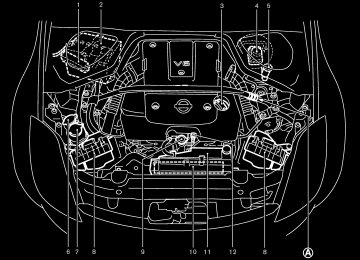
INSTRUMENT PANEL
Instrument brightness control switch
1. Headlight/turn signal switch 2. 3. Steering wheel switch for audio control (if so equipped) or switch for Bluetooth Hands- Free Phone System (if so equipped)
4. Driver supplemental air bag/Horn 5. Meters/gauges 2-2 Instruments and controls
SIC3266
6. Cruise control main/set switch
(if so equipped)
7. Trip computer mode/setting switch 8. Wiper/washer switch 9. Center ventilator 10. Passenger supplemental air bag
11. Side ventilator 12. Soft
models)
top operating switch (for Roadster
13. VDC (Vehicle dynamic control) OFF switch (if so equipped) or TCS (Traction control system) OFF switch (if so equipped)
14. Fuel-filler door opener switch 15. Hood lock release handle 16. Fuse box 17. Tilting steering wheel lock lever 18. 19. Navigation system display* or Instrument
Ignition switch/steering lock
pocket
20. Audio system/Clock 21. Rear window and outside mirror defroster
switch
22. Hazard warning flasher switch 23. Cup holder 24. Heated seat switch (if so equipped) 25. Heater/air conditioner control 26. Power outlet *: Refer
to the separate Navigation System
Owner’s Manual.
墌 06.10.24/Z33-D/V5.0 墍
METERS AND GAUGES
8. Automatic transmission position indicator or
Manual transmission shift up indicator (See “Driving the vehicle” in the “5. Starting and driving” section.)
9. Reset knob for trip odometer 10. Odometer (Total/Twin trip) 11. Trip computer setting switch
(See “Trip computer” later in this section.)
12. Trip computer mode switch
(See “Trip computer” later in this section.)
Combination meter: 1. Warning/Indicator lights 2. Turn signal/hazard indicator lights 3. Tachometer 4. Speedometer
SIC3329
5.
Instrument brightness control switch (See “Headlight and turn signal switch” later in this section.)
6. Fuel gauge 7. Engine coolant temperature gauge
Instruments and controls 2-3
墌 06.10.24/Z33-D/V5.0 墍
The odometer records the total distance the vehicle has been driven. The twin trip odometer records the distance of individual trips.
Triple meter: 1. Trip computer 2. Engine oil pressure gauge 3. Volt meter
2-4 Instruments and controls
SIC1948
SIC1949A
쎻1 Speedometer 쎻2 Odometer 쎻3 Twin trip odometer 쎻4 Reset knob for trip odometer SPEEDOMETER AND ODOMETER Speedometer The speedometer indicates vehicle speed in miles per hour (MPH) and kilometers per hour (km/h). Odometer/Twin trip odometer The odometer/twin trip odometer are displayed when the ignition switch is in the ON position.
墌 06.10.24/Z33-D/V5.0 墍
Changing the display: Pushing the reset knob changes the display as follows: TRIP A → TRIP B → TRIP A Resetting the trip odometer: Pushing the reset knob for more than 1 second resets the trip odometer to zero.
SIC3328
SIC2371A
TACHOMETER The tachometer indicates engine speed in revo- lutions per minute (rpm). Do not rev engine into the red zone 쎻A .
CAUTION
When engine speed approaches the red zone, shift to a higher gear. Operating the engine in the red zone may cause serious engine damage.
ENGINE COOLANT TEMPERATURE GAUGE The gauge indicates the engine coolant tem- perature. The engine coolant temperature is within the normal range 쎻A when the gauge needle points within the zone shown in the illustration. The engine coolant temperature will vary with the outside air temperature and driving conditions.
Instruments and controls 2-5
墌 06.10.24/Z33-D/V5.0 墍
CAUTION
If the gauge indicates a coolant tem- perature near the hot (H) end of the normal range, reduce vehicle speed to decrease the temperature. If the gauge is over the normal range, stop the ve- hicle as soon as safely possible. If the engine is overheated, continued opera- tion of the vehicle may seriously dam- age the engine. See “If your vehicle overheats” in the “6. In case of emer- gency” section for immediate action re- quired.
SIC2556
FUEL GAUGE The gauge indicates the approximate fuel level in the tank. The gauge may move slightly during braking, turning, acceleration, or going up or down hill. The gauge needle is designed to move to the E (Empty) position when the ignition key is turned to the OFF position. Refill the fuel tank before the gauge regis- ters the E (Empty) position.
The low fuel warning light comes on when the fuel tank is getting low. Refuel as soon as it is convenient, preferably before the gauge reaches the E position. There will be a small reserve of fuel in the tank when the fuel gauge needle reaches the E position. The the fuel-filler door is located on the passenger’s side of the vehicle.
indicates that
CAUTION
indicator
malfunction
쐌 If the vehicle runs out of fuel, the light (MIL) may come on. Refuel as soon as possible. After a few driving trips, light should turn off. If the the light remains on after a few driving trips, have the vehicle inspected by a NISSAN dealer.
쐌 For additional information, see “Mal- function indicator light (MIL)” later in this section.
2-6 Instruments and controls
墌 06.10.24/Z33-D/V5.0 墍
SIC1954A
Type A
ENGINE OIL PRESSURE GAUGE The gauge indicates the engine lubrication sys- tem oil pressure while the engine is running. When the engine speed is high, the engine oil pressure is also high. When it is low, the gauge indicates the low oil pressure.
operation in such a condition could cause serious damage to the engine.
SIC1953A
Type B
CAUTION
쐌 This gauge is not designed to indi- cate low engine oil level. Use the dipstick to check the oil level. (See “Engine oil” in the “8. Maintenance and do-it-yourself” section.)
쐌 If the gauge needle does not move with the proper amount of engine oil, have the vehicle checked by a NISSAN dealer. Continued vehicle
Instruments and controls 2-7
墌 06.10.24/Z33-D/V5.0 墍
SIC1955
SIC3357
SIC2997
VOLT METER When the ignition switch is turned to the ON position, the volt meter indicates the battery voltage; while the engine is running, it indicates the alternator voltage of 11 - 15 volts (normal range 쎻A ). However, while cranking the engine, the volts drop below the normal range. If the needle is not in the normal range 쎻A while the engine is running, it may indicate that the charging system is not functioning properly. Have the system checked by a NISSAN dealer.
2-8 Instruments and controls
TRIP COMPUTER The display of the trip computer is situated in the triple meter. When the ignition switch is turned to ON, the display scrolls all the modes of the trip computer and then shows the mode chosen before the ignition switch is turned OFF.
Switches for the trip computer are located on the side of the combination meter panel. To operate the trip computer, push the side of the switches as shown above. 쎻A : Trip computer mode switch 쎻B : Trip computer setting switch When the ignition switch is turned to ON, modes of the trip computer can be selected by pushing the trip computer mode switch 쎻A . Each time the mode switch 쎻A is pushed, the display will change as follows: Speed indicator → Outside air temperature (ICY) → Distance to empty (dte) → Average fuel
墌 06.10.24/Z33-D/V5.0 墍
consumption and speed → Elapsed time and trip odometer → Stopwatch → Up-shift indica- tor setting (for M/T models) → Speed indicator Speed indicator (mph or km/h) The vehicle speed is displayed in MPH or km/h while driving. The speed indicator in the trip computer indicates the reference speed. The actual speed indicated by the speedometer (com- bination meter) may differ from the one in the trip computer. Outside air temperature (ICY — °F or °C) The outside air temperature is displayed in °F or °C in the range of −22 to 131°F (−30 to 55°C). The outside air temperature mode includes a low temperature warning feature: below 37°F (3°C), the outside air temperature mode is automati- cally selected and the ICY indicator will illumi- nate in order to draw the driver’s attention. Push the mode switch 쎻A if you wish to return to the mode that was selected before the warning occurred. The ICY indicator will continue blink- ing as long as the temperature remains below 39°F (4°C). The ambient temperature sensor is located in front of the radiator. The sensor may be affected
temperature or
by road or engine heat, wind directions and other driving conditions. The display may differ from the actual ambient the temperature displayed on various signs or bill- boards. Distance to empty (dte — mls or km) The distance to empty (dte) mode provides you with an estimation of the distance that can be driven before refueling. The dte is constantly being calculated, based on the amount of fuel in the fuel tank and the actual fuel consumption.
The display is updated every 30 seconds.
The dte mode includes a low range warning feature: when the fuel level is low, the dte mode is automatically selected and the digits blink in order to draw the driver’s attention. Press the mode switch 쎻A if you wish to return to the mode that was selected before the warning occurred. The dte indicator will remain blinking until the vehicle is refueled.
level drops even lower, the dte
When the fuel display will change to (----). NOTE: 쐌 If the amount of fuel added while the ignition switch is OFF is small, the dis- play just before the ignition switch is
turned OFF may continue to be dis- played.
쐌 When driving uphill or rounding curves, the fuel in the tank shifts, which may momentarily change the display.
Average fuel consumption (mpg or l (liter)/100 km) and speed (av. mph or av. km/h) Fuel consumption:
The average fuel consumption mode shows the average fuel consumption since the last reset. Resetting is done by pushing the trip computer setting switch 쎻B for more than approximately 1
second. (The average speed is also reset at the same time.)The display is updated every 30 seconds. At about the first 1/3 miles (500 m) after a reset, the display shows (----). Speed:
The average speed mode shows the average vehicle speed since the last reset. Resetting is done by pushing the setting switch 쎻B for more than approximately 1 second. (The average fuel consumption is also reset at the same time.)
The display is updated every 30 seconds. The
Instruments and controls 2-9
墌 06.10.24/Z33-D/V5.0 墍
Display priority If a low outside air temperature warning, low dte (distance to empty) range warning and low tire pressure warning occur simul- taneously, other display modes switch au- tomatically to the outside air temperature display. When trip computer mode switch 쎻A is pressed, the display switches to the mode chosen before the warning display, but the ICY indicator will continue blinking.
first 30 seconds after a reset, the display shows (----). Elapsed time (h:m:s) and trip odometer (mls or km) Elapsed time:
The elapsed time mode shows the time since the last reset. The displayed time can be reset by pushing the trip computer setting switch 쎻B for more than approximately 1 second. (The trip odometer is also reset at the same time.) Trip odometer: The trip odometer mode shows the total dis- tance the vehicle has been driven since the last reset. Resetting is done by pushing the setting switch 쎻B for more than approximately 1 second. (The elapsed time is also reset at the same time.) Stopwatch (h:m:s) You can use the trip computer as a stopwatch. Each time the trip computer setting switch 쎻B is pushed, the stopwatch will be operated as fol- lows:
After 100 hours, the time will start from the reset display again. 2-10 Instruments and controls
Even if the display is switched to the other mode while the time is starting, the stopwatch contin- ues to advance until you stop the time in the stopwatch mode. When the ignition switch is turned to the OFF position, the time is reset. Up-shift indicator setting (rpm) (for manual transmission models) The up-shift indicator setting mode is used to set the desired engine speed (rpm) for the up-shift indicator (situated in the tachometer) to illuminate. When the engine speed approaches or reaches the set figure, the up-shift indicator will flash or illuminate to show the driver the timing for shifting into a higher gear. See “Driving the vehicle” in the “5. Starting and driving” section for the use of the up-shift indicator. When the up-shift indicator setting mode is selected, the rpm indicator blinks and the engine speed currently set (The initial factory setting is 7,500 rpm.) The figure can be changed between 2,000 and 9,000 rpm by pushing trip computer setting switch 쎻B . Press- ing the switch for less than approximately 1
second will add the figure by 100 rpm. If pushing for more than approximately 1 second, the figure will increase by 500 rpm. If the battery cable is disconnected, the set engine speed will be returned to the initial figure (7,500 rpm).is displayed.
墌 06.10.24/Z33-D/V5.0 墍
WARNING/INDICATOR LIGHTS AND AUDIBLE REMINDERS
Anti-lock Braking System (ABS) warning light
Automatic transmission check warning light (A/T models)
Low washer fluid warning light
High beam indicator light (Blue)
Seat belt warning light
Malfunction Indicator Light (MIL)
Brake warning light
Supplemental air bag warning light
Slip indicator light
or
or
Charge warning light
Door open warning light
Engine oil pressure warning light
Automatic transmission position indicator light (A/T models) Cruise main switch indicator light (if so equipped) Cruise set switch indicator light (if so equipped)
Traction Control System (TCS) off indica- tor light (if so equipped) Vehicle Dynamic Control (VDC) off indi- cator light (if so equipped)
Soft top indicator light (Roadster models)
Low tire pressure warning light
Front passenger air bag status light
Turn signal/hazard indicator lights
CHECKING BULBS Apply the parking brake and turn the ignition key to ON without starting the engine. The following lights will come on:
or
The following lights come on briefly and then go off:
or
If any light fails to come on, it may indicate a burned-out bulb or an open circuit in the elec-
system. Have the system repaired
trical promptly. WARNING LIGHTS
or
Anti-lock Braking System (ABS) warning light
When the ignition switch is in the ON position, the Anti-lock Braking System (ABS) warning light illuminates and then turns off. This indicates the ABS is operational.
If the ABS warning light illuminates while the engine is running, or while driving, it may indicate the ABS is not functioning properly. Have the system checked by a NISSAN dealer. If an ABS malfunction occurs, the anti-lock function is turned off. The brake system then operates normally, but without anti-lock assis- tance. See “Brake system” in the “5. Starting and driving” section.
Instruments and controls 2-11
墌 06.10.24/Z33-D/V5.0 墍
Automatic transmission check warning light (A/T models)
When the ignition switch is turned to the ON position, the automatic transmission check warning light comes on and then turns off. This indicates that the automatic transmission system is operational. If the light comes on while the engine is running or while driving, it may indicate that the auto- matic transmission system is not functioning properly. Have a NISSAN dealer check and repair the transmission.
or
Brake warning light
This light functions for both the parking brake and the foot brake systems. Parking brake indicator: When the ignition switch is in the ON position, the light comes on when the parking brake is applied. Low brake fluid warning light: The light warns of a low brake fluid level. If the light comes on while the engine is running with the parking brake not applied, stop the vehicle and perform the following: 1. Check the brake fluid level. Add brake fluid as necessary. See “Brake and clutch fluid” in the “8. Maintenance and do-it-yourself” section.
2-12 Instruments and controls
WARNING
쐌 Your brake system may not be work- ing properly if the warning light is on. Driving could be dangerous. If you judge it to be safe, drive carefully to the nearest service station for re- pairs. Otherwise, have your vehicle towed because driving it could be dangerous.
쐌 Pressing the brake pedal with the engine stopped and/or a low brake fluid level may increase your stop- ping distance and braking will re- quire greater pedal effort as well as pedal travel.
쐌 If the brake fluid level is below the MINIMUM or MIN mark on the brake fluid reservoir, do not drive until the brake system has been checked at a NISSAN dealer.
2.
If the brake fluid level is correct, have the warning system checked by a NISSAN dealer.
Anti-lock Braking System (ABS) warning indicator:
When the parking brake is released and the brake fluid level is sufficient, if both the brake warning light and the ABS warning light illumi- nate, it may indicate the ABS is not functioning properly. Have the brake system checked by a NISSAN dealer. See “Anti-lock Braking System (ABS) warning light” earlier in this section.
Charge warning light
If the light comes on while the engine is running, it may indicate that the charging system is not functioning properly. Turn the engine off and check the alternator belt. If the belt is loose, broken, missing or if the light remains on, see a NISSAN dealer immediately.
CAUTION
Do not continue driving if the belt is loose, broken or missing.
Door open warning light
This light comes on when any of the doors and/or rear hatch are not closed securely while the ignition switch is in the ON position.
墌 06.10.24/Z33-D/V5.0 墍
Engine oil pressure warning light
This light warns of low engine oil pressure. If the light flickers or comes on during normal driving, pull off the road in a safe area, stop the engine immediately and call a NISSAN dealer or other authorized repair shop. The engine oil pressure warning light is not designed to indicate a low oil level. Use the dipstick to check the oil level. See “Engine oil” in the “8. Maintenance and do-it-yourself” section.
CAUTION
Running the engine with the engine oil pressure warning light on could cause serious damage to the engine almost immediately. Turn off the engine as soon as it is safe to do so.
Low tire pressure warning light Your vehicle is equipped with a tire pressure monitoring system (TPMS) that monitors the tire pressure of all tires except the spare.
The low tire pressure warning light warns of low
tire pressure or indicates that the TPMS is not functioning properly.
After the ignition switch is turned ON, this light illuminates for about 1 second and turns off. Low tire pressure warning:
If the vehicle is being driven with low tire pres- sure, the warning light will illuminate.
When the low tire pressure warning light illumi- nates, you should stop and adjust the tire pres- sure to the recommended COLD tire pressure shown on the Tire and Loading Information label. The low tire pressure warning light does not automatically turn off when the tire pressure is adjusted. After the tire is inflated to the recom- mended pressure, the vehicle must be driven at speeds above 16 MPH (25 km/h) to activate the TPMS and turn off the low tire pressure warning light. Use a tire pressure gauge to check the tire pressure. For additional information, see “Tire pressure monitoring system (TPMS)” in the “5. Starting and driving” section and in the “6. In case of emergency” section. TPMS malfunction: If the TPMS is not functioning properly, the low tire pressure warning light will flash for approxi- mately 1 minute when the ignition switch is
turned ON. The light will remain on after the 1
minute. Have the system checked by a NISSAN dealer.For additional information, see “Tire pressure monitoring system (TPMS)” in the “5. Starting and driving” section.
WARNING
쐌 If the light does not illuminate with the ignition switch turned ON, have the vehicle checked by a NISSAN dealer as soon as possible.
쐌 If the light illuminates while driving, avoid sudden steering maneuvers or abrupt braking, reduce vehicle speed, pull off the road to a safe location and stop the vehicle as soon as pos- sible. Serious vehicle damage could occur and may lead to an accident and could result in serious personal injury. Check the tire pressure for all four tires. Adjust the tire pressure to the recommended COLD tire pres- sure shown on the Tire and Loading Information label to turn the low tire
Instruments and controls 2-13
墌 06.10.24/Z33-D/V5.0 墍
pressure warning light OFF. If the light still comes on while driving after adjusting the tire pressure, a tire may be flat. If you have a flat tire, replace it with a spare tire as soon as pos- sible.
쐌 When a spare tire is mounted or a wheel is replaced, the TPMS will not function and the low tire pressure warning light will flash for approxi- mately 1 minute. The light will remain on after the 1 minute. Contact your NISSAN dealer as soon as possible for tire replacement and/or system resetting.
쐌 Replacing tires with those not origi- nally specified by NISSAN could af- fect the TPMS.
the proper operation of
CAUTION
쐌 The TPMS is not a substitute for the regular tire pressure check. Be sure
2-14 Instruments and controls
to check the tire pressure regularly.
쐌 If
the vehicle is being driven at speeds of less than 16 MPH (25
km/h), the TPMS may not operate correctly.쐌 Be sure to install the specified size of
tires to the front and rear.
Low washer fluid warning light This light comes on when the washer fluid is at a low level. Add washer fluid as necessary. See “Window washer fluid” in the “8. Maintenance and do-it-yourself” section.
Seat belt warning light
The seat belt warning light and chime remind you to fasten seat belts. The light illuminates when- ever the ignition key is turned to ON, and will remain illuminated until the driver’s seat belt is fastened.
The seat belt warning light may also illuminate if the front passenger’s seat belt is not fastened when the front passenger’s seat is occupied. For 5 seconds after the ignition switch is in the ON position, the system does not activate the warn- ing light for the front passenger.
See “Seat belts” in the “1. Safety — Seats, seat belts and supplemental restraint system” section for precautions on seat belt usage.
Supplemental air bag warning light
After turning the ignition key to the ON position, the supplemental air bag warning light will illu- minate. The supplemental air bag warning light will turn off after about 7 seconds if the system is operational. If any of the supplemental front air bag, supplemental side air bag (if so equipped) and curtain side-impact air bag (if so equipped), and pre-tensioner seat belt systems need servicing and your vehicle must be taken to a NISSAN dealer. 쐌 The supplemental air bag warning light re-
the following conditions occur,
mains on after approximately 7 seconds.
쐌 The supplemental air bag warning light
flashes intermittently.
쐌 The supplemental air bag warning light does
not come on at all.
Unless checked and repaired, the supplemental restraint system (air bag system) and/or the pre-tensioner seat belt may not function prop- erly. For additional information, see “Supplemen- tal restraint system” in the “1. Safety — Seats,
墌 06.10.24/Z33-D/V5.0 墍
seat belts and supplemental restraint system” section.
Cruise main switch indicator light (if so equipped)
High beam indicator light (Blue)
WARNING
is on,
it could mean that
If the supplemental air bag warning light the supplemental front air bag, supplemen- tal side air bag, curtain side-impact air bag systems and/or pre-tensioner seat belt systems will not operate in an acci- dent. To help avoid injury to yourself or others, have your vehicle checked by a NISSAN dealer as soon as possible.
INDICATOR LIGHTS
Automatic transmission position indicator light (A/T models)
When the ignition key is turned to the ON position, the indicator in the tachometer shows the automatic transmission selector lever posi- tion. See “Driving the vehicle” (automatic trans- mission) in the “5. Starting and driving” section.
The light comes on when the cruise control main switch is pushed. The light goes out when the main switch is pushed again. When the cruise main switch indicator light comes on, the cruise control system is operational.
Cruise set switch indicator light (if so equipped)
The light comes on while the vehicle speed is controlled by the cruise control system. If the light blinks while the engine is running, it may indicate the cruise control system is not func- tioning properly. Have the system checked by a NISSAN dealer.
Front passenger air bag status light
The front passenger air bag status light ) will be lit and the passenger front air bag will be OFF depending on how the front passen- ger seat is being used.
For front passenger air bag status light opera- tion, see “NISSAN advanced air bag system” in the “1. Safety — Seats, seat belts and supple- mental restraint system” section of this manual.
This light comes on when the headlight high beam is on and goes out when the low beam is selected.
Malfunction Indicator Light (MIL)
If the Malfunction Indicator Light (MIL) comes on steady or blinks while the engine is running, it may indicate a potential emission control mal- function. The malfunction indicator light may also come on steady if the fuel-filler cap is loose or missing, or if the vehicle runs out of fuel. Check to make sure the fuel-filler cap is installed and closed tightly, and that the vehicle has at least 3 US gallons (14
liters) of fuel in the fuel tank. After a few driving trips, the light should turn off if no other potential emission control system malfunction exists. If this indicator light comes on steady for 20
seconds and then blinks for 10 seconds when the engine is not running, it indicates that the vehicle is not ready for an emission control system inspection/maintenance test. See “Readiness for inspection/maintenance (I/M) test” in the “9. Technical and consumer informa- Instruments and controls 2-15墌 06.10.24/Z33-D/V5.0 墍
tion” section of this manual. Operation
The malfunction indicator light will come on in one of two ways: 쐌 Malfunction indicator light on steady — An emission control system malfunction has been detected. Check the fuel-filler cap. If the fuel-filler cap is loose or missing, tighten or the cap and continue to drive the install vehicle. The light should turn off after a few driving trips. If the light does not turn off after a few driving trips, have the vehicle inspected by a NISSAN dealer. You do not need to have your vehicle towed to the dealer.
쐌 Malfunction indicator light blinking — An en- gine misfire has been detected which may damage the emission control system. To re- duce or avoid emission control system dam- age: a) Do not drive at speeds above 45 MPH
(72 km/h).
b) Avoid hard acceleration or deceleration. c) Avoid steep uphill grades. d) If possible, reduce the amount of cargo
being hauled or towed. The malfunction indicator blinking and come on steady. 2-16 Instruments and controls
light may stop
Have the vehicle inspected by a NISSAN dealer. You do not need to have your vehicle towed to the dealer.
CAUTION
Continued vehicle operation without having the emission control system checked and repaired as necessary could lead to poor driveability, reduced fuel economy, and possible damage to the emission control system.
Slip indicator light
The light will blink when the Vehicle Dynamic Control (VDC) system or the Traction Control System (TCS) is operating, thus alerting the driver to the fact that the road surface is slippery and the vehicle is nearing its traction limits.
This light also comes on when the ignition switch is turned to the ON position. The light will turn off if the VDC or TCS is operational.
Traction Control System (TCS) off indicator light (if so equipped)
The light comes on when the Traction Control
System (TCS) off switch is pushed to OFF. This indicates the TCS is not operating.
This light also comes on when the ignition switch is turned to the ON position. The light will turn off if the TCS is operational.
When the TCS off indicator light and slip indi- cator light come on with the TCS turned on, this light alerts the driver to the fact that the system’s fail-safe mode is operating, that is the TCS may not be functioning properly. Have the system checked by a NISSAN dealer. If a malfunction occurs in the system, the traction control func- tion will be canceled but the vehicle is still driveable. For additional information, see “Trac- tion Control System (TCS)” in the “5. Starting and driving” section of this manual.
Vehicle Dynamic Control (VDC) off indicator light (if so equipped)
The light comes on when the Vehicle Dynamic Control (VDC) off switch is pushed to OFF. This indicates the VDC system and Traction Control System (TCS) are not operating. This light also comes on when the ignition switch is turned to the ON position. The light will turn off if the VDC system is operational. When the VDC off indicator light and slip indi-
墌 06.10.24/Z33-D/V5.0 墍
cator light come on with the VDC system turned on, this light alerts the driver to the fact that the system’s fail-safe mode is operating, that is the VDC system may not be functioning properly. Have the system checked by a NISSAN dealer. If a malfunction occurs in the system, the VDC system function will be canceled but the vehicle is still driveable. For additional information, see “Vehicle Dynamic Control (VDC) system” in the “5. Starting and driving” section of this manual.
Soft top indicator light (Roadster models)
This light illuminates when the soft top is being operated or it is stopped before reaching a full open/close state. When the top is fully opened, the light will turn off. When the top is fully closed, the light will flash. The soft top can be moved with the soft top operating switch only under all of the following conditions: 쐌 When the vehicle is stopped. 쐌 When the foot brake pedal is depressed. 쐌 When the ignition switch is ON.
CAUTION
Operate the soft top with the engine running to prevent a discharged battery.
When the soft top is in motion, and any of the above conditions are discontinued or the pas- senger power seat switches (on the cushion or the seatback) are operated, the top will stop moving. Remove your hand from the operating switch, and push it again under the above conditions until the top is fully opened or closed. The soft top indicator light will turn off when the top open operation is completely finished. When closing the top, the light, which is illuminated, will begin to flash when the top close operation is completely finished. Securely engage the top to the vehicle by operating the top latch lever. The light will turn off. If the soft top indicator light flashes with the ignition switch ON (whether the top is operated or not, and when the top is engaged), it may indicate the electric soft top control unit is not functioning properly. Have your vehicle checked by a NISSAN dealer as soon as possible. For more details about top the electric soft operation, see “Soft top” in the “3. Pre-driving checks and adjustments” section.
Turn signal/hazard indicator lights
The light flashes when the turn signal switch lever or hazard switch is turned on. AUDIBLE REMINDERS Key reminder chime The chime will sound if the driver’s side door is opened while the key is left in the ignition switch (ignition switch is turned off). Remove the key and take it with you when leaving the vehicle. Light reminder chime The chime will sound when the driver’s door is opened with the headlight switch on unless the key is in the ignition switch. Make sure to turn the light switch off when you leave the vehicle. Seat belt warning chime The chime will sound for about 6 seconds unless the driver’s seat belt is securely fastened. Brake pad wear warning The disc brake pads have audible wear warn- ings. When a brake pad requires replacement, it will make a high pitched scraping sound when the vehicle is in motion whether or not the brake pedal is depressed. Have the brakes checked as Instruments and controls 2-17
墌 06.10.24/Z33-D/V5.0 墍
soon as possible if the warning sound is heard.
SECURITY SYSTEMS
SIC2132
Your vehicle has two types of security systems, as follows: 쐌 Vehicle Security System 쐌 NISSAN Vehicle Immobilizer System The security condition will be shown by the security indicator light. VEHICLE SECURITY SYSTEM The vehicle security system provides visual and audible alarm signals if someone opens the doors or rear hatch/trunk lid when the system is armed. It is not, however, a motion detection type system that activates when a vehicle is
moved or when a vibration occurs. The system helps deter vehicle theft but cannot prevent it, nor can it prevent the theft of interior or exterior vehicle components in all situations. Always secure your vehicle even if parking for a brief period. Never leave your keys in the vehicle, and always lock the vehicle when unattended. Be aware of your surroundings, and park in secure, well-lit areas whenever possible. Many devices offering additional protection, such as component locks, identification markers, and tracking systems, are available at auto sup- ply stores and specialty shops. A NISSAN dealer may also offer such equipment. Check with your insurance company to see if you may be eligible for discounts for various theft protection fea- tures.
2-18 Instruments and controls
墌 06.10.24/Z33-D/V5.0 墍
SIC1699A
Security indicator light This light 쎻A blinks whenever the ignition switch is in the LOCK, OFF or ACC position. This is normal. How to arm the vehicle security system 1. Close all windows. The system can be activated even if the windows are open.
2. Remove the key from the ignition switch.
3. Close and lock all doors and rear hatch/trunk
UNLOCK
button on the keyfob.
lid.
Lock all doors by using the key or the keyfob. When using the keyfob, the hazard indicators flash twice to indicate all doors are locked.
4. Confirm that
the security indicator
light comes on. The security indicator light glows for about 30 seconds and then blinks. The system is now activated. If, during this 30
second time period, the door is unlocked by the key or the keyfob, or the ignition key is turned to ACC or ON, the system will not activate.Even when the driver and/or passengers are in the vehicle, the system will activate with all doors and rear hatch/trunk lid locked and ignition key off. Turn the igni- tion key to ACC to turn the system off. Vehicle security system activation The security system will give the following alarm: 쐌 The headlights blink and the horn sounds
intermittently.
쐌 The alarm automatically turns off after ap- proximately 50 seconds. However, the alarm reactivates if the vehicle is tampered with again. The alarm can be shut off by unlocking a door with the key, or by pushing the
The alarm is activated by: 쐌 Opening the door without using the key or
keyfob.
쐌 Opening the rear hatch or the trunk lid with-
out using the keyfob.
How to stop an activated alarm The alarm will stop only by unlocking a door with but- the key, or by pushing the UNLOCK ton on keyfob. The alarm will not stop if the ignition key is turned to ACC or ON. If the system does not operate as de- scribed above, have it checked by a NISSAN dealer. NISSAN VEHICLE IMMOBILIZER SYSTEM The NISSAN Vehicle Immobilizer System will not allow the engine to start without the use of the registered key.
If the engine fails to start using the registered key (for example, when interference is caused by another registered key, an automated toll road device or automated payment device on the key ring), restart the engine using the following procedures:
Instruments and controls 2-19
墌 06.10.24/Z33-D/V5.0 墍
1. Leave the ignition switch in the ON position
for approximately 5 seconds.
2. Turn the ignition switch to the OFF or LOCK position and wait approximately 10 seconds.
3. Repeat steps 1 and 2.
4. Restart the engine while holding the device (which may have caused the interference) separate from the registered key. If this procedure allows the engine to start, NISSAN recommends placing the registered key on a separate key ring to avoid interfer- ence from other devices.
Statement related to section 15 of FCC rules for NISSAN Vehicle Immobilizer Sys- tem (CONT ASSY-BCM, ANT ASSY- IMMOBILIZER) This device complies with part 15 of the FCC Rules and RSS-210 of Industry Canada. Operation is subject to the follow- ing two conditions; (1) This device may not cause harmful in- terference, and (2) this device must accept any interference received, including inter- ference that may cause undesired opera- tion of the device. CHANGES OR MODIFICATIONS NOT EX- PRESSLY APPROVED BY THE PARTY RE- 2-20 Instruments and controls
SPONSIBLE FOR COMPLIANCE COULD VOID THE USER’S AUTHORITY TO OPER- ATE THE EQUIPMENT.
SIC1699A
Security indicator light This light 쎻A blinks whenever the ignition switch is in the LOCK, OFF or ACC position. This function indicates the security system equipped on the vehicle is operational.
If the NISSAN Vehicle Immobilizer System is malfunctioning, this light will remain on while the ignition switch is in the ON position. If the light still remains on and/or the engine will not start, see a NISSAN dealer for NISSAN Vehicle Immobilizer System service as soon as possible. Bring all reg- istered keys that you have when visiting a
墌 06.10.24/Z33-D/V5.0 墍
NISSAN dealer for service.
WINDSHIELD WIPER AND WASHER SWITCH
The windshield wiper and washer operates when the ignition switch is in the ON position.
SIC2998
Push the lever down to operate the wiper at the following speed: 쎻1 Intermittent (INT) — intermittent operation can be adjusted by turning the knob toward 쎻A (Slower) or 쎻B (Faster).
쎻2 Low (LO) — continuous low speed operation 쎻3 High (HI) — continuous high speed operation Push the lever up 쎻4
to have one sweep operation (MIST) of the wiper. Pull the lever toward you 쎻5to operate the
washer. Then the wiper will also operate several times.
WARNING
In freezing temperatures the washer so- lution may freeze on the windshield and obscure your vision which may lead to an accident. Warm the windshield with the defroster before you wash the wind- shield.
CAUTION
쐌 Do not operate the washer continu-
ously for more than 30 seconds.
쐌 Do not operate the washer if the
reservoir tank is empty.
쐌 Do not fill the window washer reser- voir tank with washer fluid concen- trates at full strength. Some methyl alcohol based washer fluid concen- trates may permanently stain the grille if spilled while filling the win- dow washer reservoir tank.
Instruments and controls 2-21
墌 06.10.24/Z33-D/V5.0 墍
REAR WINDOW WIPER AND WASHER SWITCH (Coupe models)
쐌 Pre-mix washer fluid concentrates with water to the manufacturer’s rec- ommended levels before pouring the fluid into the window washer reser- voir tank. Do not use the window washer reservoir tank to mix the washer fluid concentrate and water.
SIC3297
The rear window wiper and washer operate when the ignition switch is in the ON position. Turn the switch clockwise from the OFF position to operate the wiper. 쎻1 Intermittent (INT) — intermittent operation
(not adjustable)
쎻2 Low (ON) — continuous low speed operation Push the switch forward 쎻3
to operate the washer. Then the wiper will also operate several times.WARNING
In freezing temperatures the washer so- lution may freeze on the rear window and obscure your vision. Warm the rear window with the defroster before you wash the rear window.
CAUTION
쐌 If the rear window wiper operation is interrupted by snow or ice, the wiper may stop moving to protect its motor. If this occurs, turn the wiper switch to OFF and remove the snow or ice on and around the wiper arms. After about 1 minute, turn the switch ON again to operate the wiper.
쐌 Do not operate the washer continu-
ously for more than 30 seconds.
쐌 Do not operate the washer if the
reservoir tank is empty.
쐌 Do not fill the window washer reser-
2-22 Instruments and controls
墌 06.10.24/Z33-D/V5.0 墍
voir tank with washer fluid concen- trates at full strength. Some methyl alcohol based washer fluid concen- trates may permanently stain the grille if spilled while filling the win- dow washer reservoir tank.
쐌 Pre-mix washer fluid concentrates with water to the manufacturer’s rec- ommended levels before pouring the fluid into the window washer reser- voir tank. Do not use the window washer reservoir tank to mix the washer fluid concentrate and water.
REAR WINDOW AND OUTSIDE MIRROR DEFROSTER SWITCH
froster.
쐌 Do not use the rear window defroster switch while the soft top is being operated or fully opened. The heat may damage the top material and/or components. (for Roadster models)
SIC3000
To defog/defrost the rear window glass and outside mirrors, start the engine and push the switch on. The indicator light 쎻A will come on. Push the switch again to turn the defroster off.
It will automatically turn off in approximately 15
minutes.CAUTION
쐌 When cleaning the inner side of the rear window, be careful not to scratch or damage the rear window de-
Instruments and controls 2-23
墌 06.10.24/Z33-D/V5.0 墍
HEADLIGHT AND TURN SIGNAL SWITCH XENON HEADLIGHTS
WARNING
HIGH VOLTAGE
쐌 When xenon headlights are on, they produce a high voltage. To prevent an electric shock, never attempt to modify or disassemble. Always have your xenon headlights replaced at a NISSAN dealer.
쐌 Xenon headlights provide consider- ably more light than conventional headlights. If they are not correctly aimed, they might temporarily blind an oncoming driver or the driver ahead of you and cause a serious accident. If headlights are not aimed correctly, immediately take your ve- hicle to a NISSAN dealer and have the headlights adjusted correctly.
When the xenon headlight is initially turned on, its brightness or color varies slightly. However, the color and brightness will soon stabilize.
2-24 Instruments and controls
쐌 The life of xenon headlights will be shortened by frequent on-off operation. It is generally desirable not to turn off the headlights for short intervals (for example, when the vehicle stops at a traffic signal). Even when the daytime running lights are active (Canada only), the xenon headlights do not turn on. This way the life of the xenon headlights is not reduced.
쐌 If the xenon headlight bulb is close to burning out, the brightness will drasti- cally decrease, the light will start blink- ing, or the color of the light will become reddish. If one or more of the above signs appear, contact a NISSAN dealer. HEADLIGHT SWITCH
SIC3291
Lighting 쎻1 Turn the switch to the
position:
The front park, side marker, tail, license plate and instrument lights will come on.
쎻2 Turn the switch to the
position:
Headlights will come on and all the other lights remain on.
墌 06.10.24/Z33-D/V5.0 墍
CAUTION
Use the headlights with the engine run- ning to avoid discharging the vehicle battery.
turn off 5 minutes after the ignition switch has been turned to the OFF position.
쐌 After the headlights automatically turn off with the headlight switch in the po- sition, the headlights will illuminate again for 5
minutes if the headlight switch is turned to the OFF position and then turned to theor
or
position.
CAUTION
Even though the battery saver feature automatically turns off the headlights after a period of time, you should turn the headlight switch to the OFF position when the engine is not running to avoid discharging the vehicle battery.
DAYTIME RUNNING LIGHT SYSTEM (Canada only) The headlights (low beam) automatically illumi- nate when the engine is started with the parking brake released. The daytime running lights op- erate with the headlight switch in the OFF position or in the If the parking brake is applied before the engine is started, the daytime running lights do not Instruments and controls 2-25
position.
SIC3315
Headlight beam select 쎻1 To select the high beam, push the lever forward. The high beam lights come on and illumi- the high beam indicator light nates.
쎻2 Pull the lever back to select the low beam. 쎻3 Pulling the lever toward you will flash the
headlight high beam. Battery saver system 쐌 When the headlight switch is in the
or position while the ignition switch is in