- 2010 Mercedes-Benz R Class Owners Manuals
- Mercedes-Benz R Class Owners Manuals
- 2006 Mercedes-Benz R Class Owners Manuals
- Mercedes-Benz R Class Owners Manuals
- 2008 Mercedes-Benz R Class Owners Manuals
- Mercedes-Benz R Class Owners Manuals
- 2009 Mercedes-Benz R Class Owners Manuals
- Mercedes-Benz R Class Owners Manuals
- 2007 Mercedes-Benz R Class Owners Manuals
- Mercedes-Benz R Class Owners Manuals
- 2011 Mercedes-Benz R Class Owners Manuals
- Mercedes-Benz R Class Owners Manuals
- Download PDF Manual
-
ically.
i If the vehicle was previously centrally locked with the SmartKey or KEYLESS-GO*, the tailgate will lock automatically after closing it. The turn signals flash three times to confirm locking.
Controls in detail Locking and unlocking
Power tailgate* In vehicles with power tailgate, you can 앫 open and close the tailgate from the
inside and the outside electrically
앫 limit the opening height of the tailgate 앫 interrupt the opening/closing proce-
dure at any time by 앫 pressing or pulling the
door-mounted remote tailgate switch (컄 page 122)
앫 pressing the Š button on the
SmartKey (컄 page 110) or SmartKey with KEYLESS-GO* (컄 page 113)
앫 pressing the tailgate closing switch
(컄 page 124)
앫 pressing the tailgate
closing/locking switch (vehicles with KEYLESS-GO*) (컄 page 125)
! The tailgate swings open upwards automat- ically. Always make sure there is sufficient over- head clearance.
121
Controls in detail Locking and unlocking
Opening the tailgate from the outside You can unlock and open the tailgate simultaneously from the outside when the vehicle is at a standstill. 왘 Press and hold button Š on the
SmartKey or SmartKey with KEYLESS-GO* until the tailgate unlocks and opens. While the tailgate is opening, an acoustic signal sounds.
or 왘 Vehicles with KEYLESS-GO*:
Pull on the handle (컄 page 120). The tailgate is unlocked and opens. While the tailgate is opening, an acoustic signal sounds.
Opening the tailgate from the inside You can unlock and open the tailgate simultaneously from the driver’s seat when the vehicle is at a standstill.
Warning!
Maintain sight of the area around the rear of the vehicle while operating the tailgate with the door-mounted remote tailgate switch or with the Š button on the SmartKey or SmartKey with KEYLESS-GO*. Monitor the opening procedure carefully to make sure no one is in danger of being injured.
To interrupt the opening procedure, press or pull the door-mounted remote tailgate switch or press the Š button on the SmartKey or SmartKey with KEYLESS-GO*.
The switch is located on the door control panel.
1 Remote tailgate switch 왘 Pull remote tailgate switch 1 until
tailgate begins to open. The tailgate opens. While the tailgate is opening, an acoustic signal sounds.
122
Limiting opening height of tailgate* In vehicles with power tailgate*, the tail- gate opening height can be limited when transporting goods on a roof rack* (e.g. presence of an MB sport luggage container*). When activated, the tailgate opens to approximately 6.4 ft (1.95 m). 왘 Activate the limiting opening height of
tailgate using the control system (컄 page 183).
Closing the tailgate from the inside You can close the tailgate from the inside using the remote tailgate switch. If the tailgate comes into contact with an object while closing (e.g. luggage that has been piled too high) the closing procedure is stopped and the tailgate reopens.
Warning!
Maintain sight of the area around the rear of the vehicle while operating the tailgate with the door-mounted switch. Monitor the closing procedure carefully to make sure no one is in danger of being injured.
To interrupt the closing procedure, press or pull the door-mounted remote tailgate switch or press the Š button on the SmartKey or SmartKey with KEYLESS-GO*.
Even with the SmartKey or the SmartKey with KEYLESS-GO* removed from the starter switch or the SmartKey with KEYLESS-GO* removed from the vehicle, the remote tailgate switch can be operated. Therefore, do not leave children unattended in the vehicle, or with access to an unlocked vehicle. A child’s unsupervised access to a vehicle could result in an accident and/or serious personal injury.
Controls in detail Locking and unlocking
왘 Press remote tailgate switch 1
(컄 page 122) until tailgate begins to close. The tailgate closes. While the tailgate is closing an acoustic signal sounds.
To interrupt the closing procedure: 왘 Press or pull remote tailgate switch 1
(컄 page 122).
123
Controls in detail Locking and unlocking
Closing the tailgate from the outside You can close the tailgate from the outside using the tailgate closing switch or the Š button on the SmartKey or SmartKey with KEYLESS-GO*. In vehicles with KEYLESS-GO*, you can also simultaneously lock the vehicle. If the tailgate comes into contact with an object while closing (e.g. luggage that has been piled too high), the closing procedure is stopped and the tailgate reopens.
Vehicles without KEYLESS-GO* 1 Tailgate closing switch
124
always keep hands and fingers away from the cargo compartment opening when clos- ing the tailgate. Be especially careful when small children are around. To stop the clos- ing procedure, do one of the following: 앫 Press tailgate closing switch 1
(컄 page 124).
앫 Press KEYLESS-GO locking/closing
switch* 1 (컄 page 125).
앫 Press the Š button on the SmartKey
(컄 page 110) or SmartKey with KEYLESS-GO* (컄 page 113).
앫 Press or pull the remote tailgate switch
on the driver’s door (컄 page 122).
Even with the SmartKey removed from the starter switch or the SmartKey with KEYLESS-GO* removed from the vehicle, the tailgate closing switch can be operated. Therefore, do not leave children unattended in the vehicle, or with access to an unlocked vehicle. A child’s unsupervised access to a vehicle could result in an accident and/or serious personal injury.
Vehicles with KEYLESS-GO* 1 Tailgate closing switch 왘 Press tailgate closing switch 1 or the
Š button on the SmartKey or SmartKey with KEYLESS-GO* briefly. The tailgate closes and an acoustic warning sounds.
Warning!
Monitor the closing procedure carefully to make sure no one is in danger of being in- jured. To prevent possible personal injury,
i Do not place the SmartKey or SmartKey with KEYLESS-GO* in the open cargo compartment. You may lock yourself out.
i If the vehicle was previously centrally locked, the tailgate will lock automatically after closing it. The turn signals will flash three times to confirm locking.
Closing the tailgate and locking the vehicle from the outside (vehicles with KEYLESS-GO*) In vehicles with power tailgate and KEYLESS-GO*, you can close the tailgate and lock the vehicle simultaneously from the outside using the KEYLESS-GO* lock- ing/closing switch. If the tailgate comes into contact with an object while closing (e.g. luggage that has been piled too high), the closing procedure is stopped and the tailgate reopens. 왘 Make sure you have the SmartKey with
KEYLESS-GO* with you.
1 KEYLESS-GO* locking/closing switch 왘 Press KEYLESS-GO* locking/closing
switch 1 briefly. The tailgate closes automatically and an acoustic warning sounds. Once the tailgate is closed, the vehicle locks if doors are closed. The turn signals flash three times to confirm locking. The locking knobs in the doors move down. The anti-theft alarm system is armed.
Controls in detail Locking and unlocking
Warning!
Monitor the closing procedure carefully to make sure no one is in danger of being in- jured. To prevent possible personal injury, always keep hands and fingers away from the cargo compartment opening when clos- ing the tailgate. Be especially careful when small children are around. To stop the clos- ing procedure, do one of the following: 앫 Press tailgate closing switch 1
(컄 page 124).
앫 Press KEYLESS-GO locking/closing
switch* 1 (컄 page 125).
앫 Press the Š button on the SmartKey
with KEYLESS-GO* (컄 page 113).
앫 Press or pull the remote tailgate switch
on the driver’s door (컄 page 122).
컄컄
125
Controls in detail Locking and unlocking
컄컄
Even with the SmartKey with KEYLESS-GO* removed from the vehicle, the tailgate closing switch can be operated. Therefore, do not leave children unattended in the ve- hicle, or with access to an unlocked vehicle. A child’s unsupervised access to a vehicle could result in an accident and/or serious personal injury.
i To prevent a possible inadvertent lockout, the tailgate will open automatically if a SmartKey with KEYLESS-GO* is recognized inside the vehicle.
126
Automatic central locking
Locking and unlocking from the inside
The doors and the tailgate lock automati- cally when the ignition is switched on and the wheels are turning at vehicle speeds of approximately 9 mph (15 km/h) or more.
i You can open a locked door from the inside. Open door only when conditions are safe to do so.
i The doors unlock automatically after an accident if the force of the impact exceeds a pre- set threshold. The vehicle automatically locks when the ignition is switched on and the wheels are turning at vehicle speeds of approximately 9 mph (15 km/h) or more. You could therefore lock yourself out when the vehicle 앫 is pushed or towed 앫 is on a test stand For information on towing the vehicle, see “Towing the vehicle” (컄 page 513). You can deactivate the automatic locking mode using the control system (컄 page 183).
You can lock or unlock the doors and the tailgate from inside using the central lock- ing or unlocking switch. This can be useful, for example, if you want to lock the vehicle before starting to drive. The fuel filler flap cannot be locked or un- locked with the central locking or unlock- ing switch.
Warning!
When leaving the vehicle, always remove the SmartKey or SmartKey with KEYLESS-GO* from the starter switch, take it with you, and lock the vehicle. Do not leave children unat- tended in the vehicle, or with access to an unlocked vehicle. A child’s unsupervised access to a vehicle could result in an accident and/or serious personal injury.
i You can open a locked door from the inside at any time. Open door only when conditions are safe to do so. If the vehicle was previously centrally locked with the SmartKey or with KEYLESS-GO*, it will not unlock using the central unlocking switch. If the vehicle was previously locked with the central locking switch: 앫 and the SmartKey or SmartKey with
KEYLESS-GO* is set to factory settings, the complete vehicle is unlocked when a front door is opened from the inside
앫 and the SmartKey or SmartKey with
KEYLESS-GO* is set to selective settings, only the front door opened from the inside is unlocked
i With the passenger-side door opened, you cannot lock the vehicle with the central locking switch.
The switches are located in the driver’s door.
1 Central unlocking switch 2 Central locking switch
Locking 왘 Press central locking switch 2.
If all doors and the tailgate are closed, the vehicle locks.
Unlocking 왘 Press central unlocking switch 1.
The vehicle unlocks.
Controls in detail Locking and unlocking
127
Controls in detail Seats
For information on seat adjustment, see the “Getting started” section (컄 page 44). For more information on folding the seats, see “Loading” (컄 page 288).
Easy-entry/exit feature
Warning!
You must make sure no one can become trapped or injured by the moving steering wheel when the easy-entry/exit feature is activated.
With the easy-entry/exit feature activated, the steering wheel will return to the last set position when you 앫 close the driver’s door with the ignition
switched on or
Easy-entry/exit feature for driver’s seat* This feature allows for easier entry into and exit from the vehicle. When entering and exiting the vehicle, the steering wheel is in its uppermost position. The easy-entry/exit feature can be activated or deactivated in the Comfort submenu of the control system (컄 page 184).
To stop steering wheel movement, do one of the following: 앫 Move steering wheel adjustment stalk*
(컄 page 47).
앫 insert the SmartKey into the starter
switch or press the KEYLESS-GO* start/stop button (컄 page 41) once with the driver’s door closed
앫 Press one of the stored position buttons* or memory button M* (컄 page 141).
Do not leave children unattended in the ve- hicle, or with access to an unlocked vehicle. Children could open the driver’s door and unintentionally activate the easy-entry/exit feature, which could result in an accident and/or serious personal injury.
i The last set steering wheel position is stored when 앫 the ignition is switched off (컄 page 39) 앫 the position is stored into memory
(컄 page 142)
128
With the easy-entry/exit feature activated, the steering wheel tilts upwards when you 앫 remove the SmartKey from the starter
switch or
앫 open the driver’s door with the
SmartKey in starter switch position 0 or 1 (컄 page 39) or the KEYLESS-GO* start/stop button in position 1 (컄 page 41)
i If the current position for the steering wheel is in the uppermost tilt position, the steering wheel will no longer be able to move upward when the easy-entry/exit feature is activated. The adjustment procedure is briefly interrupted, when the engine is started.
Warning!
Let the system complete the adjustment procedure before setting the vehicle in mo- tion. All steering wheel adjustments must be completed before setting the vehicle in mo- tion. Driving off with the steering wheel still adjusting could cause the driver to lose con- trol of the vehicle.
Easy-entry/exit feature for third-row seats This feature allows for easier access to and exit from the vehicle’s third-row seats.
Warning!
To help avoid personal injury, the sec- ond-row seat backrests must be properly locked either in the upright position or, when using the expanded cargo compart- ment, in the fully folded position while the vehicle is in motion.
Controls in detail Seats
! 7-seat vehicles*: Do not use the driver’s side easy-entry/exit fea- ture for third-row seats when the second-row middle seat is in armrest position. Otherwise, the seat belt outlet of the second-row middle seat could damage the seat backrest of the outboard seat.
Easy-entry feature for third-row seats The releases for the easy-entry feature are located on the entry side and the back of each outboard second-row seat.
1 Easy-entry lever
컄컄
129
Controls in detail Seats
컄컄
왘 Pull and hold easy-entry lever 1 in
direction of arrow at resistance point. The seat backrest folds forward.
Easy-exit feature for third-row seats The easy-exit strap is located on the rear of each outboard second-row seat base.
왘 Push the seat forward as far as it will
go. You should now have sufficient space to access the vehicle’s third-row seat.
Easy-entry/exit position 왘 Exit the vehicle. For information on how to fold down the second-row seats completely, see “Folding outboard second-row seats” (컄 page 294).
1 Easy-exit strap 왘 To exit the vehicle when seated on a
third-row seat, pull up and hold easy-exit strap 1. The second-row seat backrest folds forward.
왘 Push second-row seat forward a far as
it will go.
Easy-entry/exit position 왘 Enter the vehicle. For information on how to fold down the second-row seats completely, see “Folding outboard second-row seats” (컄 page 294).
130
Returning outboard second-row seats to their original position
Warning
When occupants have entered or exited the vehicle using the easy-entry/exit feature, before driving off make sure 앫 the outboard second-row seats are
properly locked
앫 the seat backrests of the outboard second-row seats are in an upright position and are properly locked
An outboard second-row seat is properly locked only when lock status indicator 1 is in hinged position and red marking 2 is barely visible.
Controls in detail Seats
If a seat and seat backrest are not properly locked, the seat could move forward and the seat backrest could fold. You could slide under the seat belt during braking, vehicle maneuvers, or in an accident. If you slide under it, the seat belt would apply force at the abdomen or neck. That could cause se- rious or even fatal injuries.
When the seat is unlocked 앫 lock status indicator 1 is extended 앫 red marking 2 is clearly visible 왘 When the seat is unlocked, push seat
backrest back until the seat audibly engages.
Seat unlocked 1 Lock status indicator 2 Red marking
Seat locked 1 Lock status indicator 2 Red marking When the seat is locked 앫 lock status indicator 1 is in hinged
position
앫 red marking 2 is barely visible
131
Controls in detail Seats
Lumbar support
Multicontour seat*
왘 Switch on the ignition (컄 page 39).
The curvature of the driver’s seat can be adjusted to help enhance lower back support and seating comfort. The lever for lumbar support adjustment is located on the right hand side of the driver’s seat backrest.
The multicontour seat has an extendable seat cushion and inflatable air chambers built into the backrest to provide additional lumbar and side support. The seat cushion depth, seat backrest cushion-height and curvature can be con- tinuously varied with switches on the in- side of each front seat base after the ignition is switched on (컄 page 39).
1 Adjustment lever 왘 Move adjustment lever 1 in direction
of arrows until you have reached a comfortable seating position.
1 Seat cushion depth 2 Backrest side bolsters 3 Backrest center 4 Backrest bottom
132
Seat cushion depth 왘 Adjust the seat cushion depth to the
length of your upper leg with switch 1.
Backrest contour 왘 Adjust the contour of the seat backrest
to the desired position with switch æ or ç.
왘 Move the seat backrest support to the bottom with button 4 or to the center with button 3.
Backrest side bolsters 왘 Adjust the side bolsters so that they
provide good lateral support with switch 2.
Controls in detail Seats
Front seat active head restraints
Rear seats
Rear seat adjustment
Warning!
Warning!
Warning!
For your protection, drive only with properly positioned head restraints.
Adjust the head restraint so that it is close to the head as possible and the center of the head restraint supports the back of the head at eye level. This will reduce the potential for injury to the head and neck in the event of an accident or similar situation.
You cannot remove the active head restraints on the driver’s and front passen- ger’s seat. For removal of the active head restraints we recommend that you contact an authorized Mercedes-Benz Light Truck Center. For information on head restraint adjust- ment, see “Seats” (컄 page 43). For information on active head restraints, see “Active head restraints” (컄 page 86).
According to accident statistics, children are safer when properly restrained in the rear seating positions than in the front seat- ing position. Thus, we strongly recommend that children be placed in the rear seats. Re- gardless of seating position, children 12 years old and under must be seated and properly secured in an appropriate infant or toddler restraint, or booster seat recom- mended for the size and weight of the child. For additional information, see “Children in the vehicle” (컄 page 87). A child’s risk of serious or fatal injuries is significantly increased if the child restraints are not properly secured in the vehicle and the child is not properly secured in the child restraint.
Never ride in a moving vehicle with the seat backrest in an excessively reclined position as this can be dangerous. You could slide under the seat belt in a collision. If you slide under it, the belt would apply force at the abdomen or neck. That could cause serious or fatal injuries. The seat backrest and seat belts provide the best restraint when the wearer is in a nearly upright position and belts are properly positioned on the body.
Your seat must be adjusted so that you can correctly fasten your seat belt (컄 page 50). Never place hands under the seat or near any moving parts while a seat is being adjusted.
컄컄
133
Controls in detail Seats
컄컄
After adjusting rear seats, make sure 앫 the seats are properly locked 앫 the seat backrests are in an upright po-
sition and are properly locked
An outboard second-row seat is properly locked only when lock status indicator 1 is in hinged position and red marking 2 is barely visible (컄 page 131). If a seat and seat backrest are not properly locked, the seat could move forward and the seat backrest could fold. You could slide un- der the seat belt during braking, vehicle ma- neuvers, or in an accident. If you slide under it, the belt would apply force at the abdomen or neck. That could cause serious or even fatal injuries.
134
Fore and aft adjustment (outboard second-row seats) The handles for adjusting the seats are located on the front of each seat base.
Seat backrest tilt (outboard second-row seats) The handles for adjusting the seats are located on the rear of each seat base.
1 Adjustment handle 왘 Pull up handle 1 in direction of arrow
and hold it there.
왘 Move seat to the desired position. 왘 Release handle 1.
The seat must audibly engage.
1 Adjustment handle 왘 While seated, pull handle 1 in direc- tion of arrow to resistance point and hold it there.
왘 To move seat backrest back, lean
lightly against backrest.
왘 To move seat backrest forward, lean
forward with handle 1 pulled and held at resistance point. The seat backrest will move forward against your back.
왘 Release handle 1 when the seat back- rest has reached the desired position. To make sure the seat backrest has engaged, lean firmly against the back- rest.
Seat backrest tilt (third-row seats) The handles for adjusting the seats are located on the outer side of each seat backrest.
1 Adjustment handle 왘 While seated, pull handle 1 in
direction of arrow and hold it there. 왘 To move seat backrest back, lean
lightly against backrest.
Controls in detail Seats
왘 To move seat backrest forward, lean
forward with handle 1 pulled. The seat backrest will move forward against your back.
왘 Release handle 1 when the seat back- rest has reached the desired position. To make sure the seat backrest has engaged, lean firmly against the back- rest.
Head restraint height
Warning!
For your protection, drive only with properly positioned head restraints.
Adjust the head restraint in such a way that it is as close to the head as possible and the center of the head restraint supports the back of the head at eye level. This will re- duce the potential for injury to the head and neck in the event of an accident or similar situation.
135
Controls in detail Seats
Outboard second-row seat head restraint 1 Head restraint 2 Release button Raising: 왘 Manually adjust the height of head
restraint 1 by pulling it upward to the desired position.
Lowering: 왘 To lower head restraint 1, press
release button 2 and push down on head restraint 1.
136
i The head restraint of the second-row middle seat* and the third-row seat head restraints are adjusted in the same manner.
i The tilt of the second-row head restraints is adjusted in the same manner as the front-seat head restraints, see “Head restraint fore and aft adjustment” (컄 page 46). The tilt of the head restraint of the second-row middle seat* and the third-row seat head restraints cannot be adjusted.
Head restraints
Warning!
With the second-row middle seat* or a third-row seat occupied, make sure to move the respective head restraint up from the lowest non-use position and have the occu- pant adjust the head restraint properly.
For your protection, drive only with properly positioned head restraints.
Adjust the head restraint in such a way that it is as close to the head as possible and the head restraint supports the back of the head at eye level. This will reduce the potential for injury to the head and neck in the event of an accident or similar situation.
Do not drive the vehicle without the seat head restraints installed when the rear seats are occupied. Head restraints are intended to help reduce injuries during an accident.
i When removing or installing the head restraint of an outboard second-row seat, adjust the seat to the rear as far as possible (컄 page 134) and fold the seat backrest (컄 page 129) forward.
Installing head restraints 왘 Insert head restraint 1 into openings
on the seat backrest.
i On the outboard second-row seats, the guide bar with the detent must be on the left. 왘 Push head restraint 1 down until it
audibly engages.
왘 Push release button 2 and adjust
head restraint 1 to the desired position (컄 page 135).
i The head restraint of the second-row middle seat* and the third-row seat head restraints are installed in the same manner.
Removing head restraints
Seat position for removal of head restraints from outboard second-row seats 1 Head restraint 2 Release button 왘 To remove head restraint 1, pull head restraint 1 to its uppermost position. 왘 Press release button 2 and pull out
head restraint 1.
i The head restraint of the second-row middle seat* and the third-row seat head restraints are removed in the same manner.
Controls in detail Seats
Armrests
6-seat vehicles The second-row seat armrests can be folded up, when loading for example, and adjusted. Folding up: 왘 Move the armrest into a vertical
position until it engages.
Adjusting: 왘 With the armrest folded up, disengage the armrest by pushing it towards the rear slightly.
왘 Fold the armrest down to the lowest
and then to the desired position until it engages.
왘 To readjust the armrest to a higher
position, move armrest up to the desired position until it engages.
i To readjust the armrest to a lower position, you must first fold up the armrest again and re- peat the steps above.
137
Controls in detail Seats
7-seat vehicles* You can use the seat backrest of the second-row middle seat as an armrest for the outboard seats.
during braking, vehicle maneuvers, or an ac- cident and be thrown around in the vehicle interior. Objects thrown around in the vehi- cle interior may cause an accident and/or serious personal injury.
왘 Pull seat backrest release strap 1 in
direction of arrow.
왘 Completely fold seat backrest 2 for-
ward so that it rests on seat cushion 3 (armrest position).
Warning
The folded second-row middle seat is in- tended to serve as an armrest only. Do not fold the second-row middle seat and allow occupants to use the folded second-row middle seat as a footrest while driving. All vehicle occupants must keep both feet on the floor in front of their seat. Otherwise, oc- cupants could slide under the seat belt in a collision. If occupants slide under it, the belt would apply force at the abdomen or neck. That could cause serious or even fatal inju- ries.
Do not fold the second-row middle seat and allow occupants to use the folded second-row middle seat as a table while driving. Objects placed on the folded second-row middle seat may move freely
138
왘 Before folding the seat, completely
lower the head restraint of the second-row middle seat (컄 page 135).
Armrest position
1 Seat backrest release strap 2 Seat backrest 3 Seat cushion
Seat heating*
The switches for front-seat heating are lo- cated in the center console.
The switches for the outboard second-row seats are located in the rear center console.
The red indicator lamps in the switch come on to show which heating level you have selected.
Controls in detail Seats
Front seat heating 1 Seat heating switch 2 Indicator lamps
Outboard second-row seat heating 1 Seat heating switch 2 Indicator lamps
Level
off
Three indicator lamps on (highest level) The seat heating automatically switches to level 2 after approxi- mately 5 minutes. Two indicator lamps on The seat heating automatically switches to level 1 after approxi- mately 10 minutes. One indicator lamp on (lowest level) The seat heating automatically switches off after approximately 20 minutes. No indicator lamp on.
왘 Switch on the ignition (컄 page 39).
139
Controls in detail Seats
Switching on 왘 Press switch 1.
Three red indicator lamps 2 in the switch come on.
왘 Continue pressing switch 1 until
desired seat heating level is reached.
Switching off 왘 Press switch 1 repeatedly until all
indicator lamps 2 go out.
i If one or more of the indicator lamps 2 on seat heating switch 1 (컄 page 139) are flash- ing, there is insufficient voltage due to too many electrical consumers being switched on. The seat heating switches off automatically. The seat heating will switch back on again automatically as soon as sufficient voltage is available.
140
Seat ventilation* (Canada only)
Seat ventilation is available on the R 550 4MATIC only. The switches for the seat ventilation are located in the center console.
1 Seat ventilation switch 2 Indicator lamps
The blue indicator lamps in the switch come on to show which ventilation level you have selected.
Level
off
Three indicator lamps on (highest level) Two indicator lamps on One indicator lamp on (lowest level) No indicator lamp on
왘 Switch on the ignition (컄 page 39).
Switching on 왘 Press switch 1 repeatedly until the
desired ventilation level is set.
i The seat ventilation for the driver’s seat is automatically set to the highest level if activated via summer opening feature (컄 page 244).
Switching off 왘 Press switch 1 repeatedly until all
indicator lamps 2 go out.
왔 Memory function* Prior to operating the vehicle, the driver should check and adjust the seat height, seat position fore and aft, and seat back- rest angle if necessary, to ensure adequate control, reach and comfort. The head restraint should also be adjusted for proper height. See also the section on air bags (컄 page 72) for proper seat position- ing. In addition, adjust the steering wheel to ensure adequate control, reach, operation and comfort. Both the interior and exterior rear view mirrors should be adjusted for adequate rear vision. Fasten seat belts. Infants and small chil- dren should be seated in a properly secured restraint system that complies with U.S. Federal Motor Vehicle Safety Standards 213 and 225 and Canadian Motor Vehicle Safety Standards 213 and 210.2.
With the memory function you can store up to three different configuration. Each stored position on the driver’s side includes the following settings: 앫 Seat position 앫 Multicontour seat*: previously saved
setting
앫 Steering wheel position 앫 Exterior rear view mirrors’ position Each stored position on the passenger side includes the following settings: 앫 Seat position 앫 Multicontour seat*: previously saved
setting
Warning!
Do not activate the memory function while driving. Activating the memory function while driving could cause the driver to lose control of the vehicle.
Controls in detail Memory function*
The memory button and stored position buttons are located on the entry side of each front seat base.
1, 2, 3
Memory button Stored position buttons
141
Controls in detail Memory function*
Storing positions into memory
Recalling positions from memory
왘 Adjust the seat (컄 page 44). 왘 On the driver’s side, additionally adjust
the steering wheel (컄 page 46) and exterior rear view mirrors (컄 page 48) to the desired positions. 왘 Press memory button M. 왘 Release memory button M and press stored position button1, 2 or 3 within 3 seconds. When the settings are stored to the selected position, an acknowledge- ment signal sounds.
! Do not operate the power seats using mem- ory button M if the seat backrest is in an exces- sively reclined position. Doing so could cause damage to front or rear seats. Move seat backrest to an upright position first. 왘 Press and hold stored position
button 1, 2 or 3 until the seat, steering wheel and exterior rear view mirrors have fully moved to the stored posi- tions.
i Releasing the stored position button stops movement to the stored positions immediately.
142
왔 Lighting For information on how to switch on the headlamps and use the turn signals, see “Switching on headlamps” (컄 page 58) and “Turn signals” (컄 page 59).
i If you drive in countries where vehicles drive on the other side of the road than the country in which the vehicle is registered, you must have the headlamps modified for symmetrical low beams. Relevant information can be obtained at any authorized Mercedes-Benz Light Truck Center.
i Vehicles with active Bi-Xenon* headlamps: The active Bi-Xenon* headlamps monitor the vehicle’s steering angle and speed, then auto- matically shift their beams to either side to better follow the curvature of the road ahead, in- creasing usable illumination over conventional headlamps.
Exterior lamp switch
1 ‚ Standing lamps, left (turn left two stops)
2 ˆ Standing lamps, right
(turn left one stop)
3 M Off
Daytime running lamp mode (컄 page 145)
4 U Automatic headlamp mode
Daytime running lamp mode (컄 page 145)
Controls in detail Lighting
5 C Parking lamps (also side marker lamps, tail lamps, license plate lamps, instrument panel lamps) 6 B Low beam headlamps or high
beam headlamps 7 ‡ Front fog lamps 8 † Rear fog lamp
i The exterior lamps switch off automatically when you remove the SmartKey from the starter switch or open the driver’s door with the ignition switched off. When the parking lamps or the rear fog lamp are switched on and you remove the SmartKey from the starter switch or open the driver’s door, an acoustic signal sounds. In addition the message Switch Off Lights appears in the multifunction display. Switch off the parking lamps or the rear fog lamp manually.
! Failure to switch off the parking lamps when leaving the vehicle may result in a discharged battery.
143
Controls in detail Lighting
Low beam headlamps 왘 Turn the exterior lamp switch to
position B. With the SmartKey in starter switch position 1 or the KEYLESS-GO* start/stop button pressed once, the following lamps will switch on: 앫 Tail and parking lamps 앫 License plate lamps 앫 Side marker lamps With the SmartKey in starter switch position 1 or the KEYLESS-GO* start/stop button pressed once, the following lamps will switch on addi- tionally: 앫 Low beam headlamps 앫 High beam headlamps (when the
combination switch is pushed forward)
144
Automatic headlamp mode The following lamps switch on and off automatically depending on the brightness of the ambient light: 앫 Low beam headlamps 앫 Tail and parking lamps 앫 License plate lamps 앫 Side marker lamps
Warning!
If the exterior lamp switch is set to U, the headlamps will not be automatically switched on under foggy conditions.
To minimize risk to you and to others, activate headlamps by turning exterior lamp switch to B when driving or when traffic and/or ambient lighting conditions require you to do so.
In low ambient lighting conditions, only switch from position U to B with the vehicle at a standstill in a safe location. Switching from U to B will briefly switch off the headlamps. Doing so while driving in low ambient lighting conditions may result in an accident.
The automatic headlamp feature is only an aid to the driver. The driver is responsible for the operation of the vehicle’s lights at all times.
왘 Turn the exterior lamp switch to
position U. With the SmartKey in starter switch position 1 or the KEYLESS-GO* start/stop button pressed once, only the parking lamps and the side marker lamps will switch on and off depending on the brightness of the ambient light. When the engine is running, the low beam headlamps, the tail and parking lamps, the license plate lamps, and the side marker lamps will switch on and off depending on the brightness of the ambient light.
i Canada only: High beam headlamps are only available with the exterior lamp switch in position B.
Controls in detail Lighting
Daytime running lamp mode In Canada the daytime running lamp mode is mandatory and therefore in a constant mode. In the USA the daytime running lamp mode is deactivated by default. Activate the day- time running lamp mode using the control system, see “Setting daytime running lamp mode (USA only)” (컄 page 177). 왘 Turn the exterior lamp switch to
position M or U. When the engine is running, the low beam headlamps are switched on. In low ambient light conditions, the following lamps will switch on addition- ally: 앫 Tail and parking lamps 앫 License plate lamps 앫 Side marker lamps
i With the daytime running lamp mode activat- ed and the engine running, you cannot switch off the low beam headlamps manually.
Canada only:
i With the exterior lamp switch in position M or U, you cannot switch on the high beam headlamps. The high beam flasher is available at all times. For nighttime driving, turn the exterior lamp switch in position B to permit activation of the high beam headlamps.
When the engine is running and you shift from a driving position to position N or P with the vehicle at a standstill, the low beam headlamps will switch off with a three-minute delay. When the engine is running and you 앫 turn the exterior lamp switch to
position C, the low beam head- lamps, the tail and parking lamps, the side marker lamps and the license plate lamps switch on
앫 turn the exterior lamp switch to
position B, the manual headlamp mode has priority over the daytime running lamp mode
145
Controls in detail Lighting
USA only
i With the daytime running lamp mode activated and the exterior lamp switch in position M, you cannot switch on the high beam headlamps. The high beam flasher is available at all times. For nighttime driving, turn the exterior lamp switch in position B or U to permit activation of the high beam headlamps.
When the engine is running, and you turn the exterior lamp switch to position C or B, the manual headlamp mode has priority over the daytime running lamp mode. The corresponding exterior lamps switch on (컄 page 143).
146
Locator lighting and night security illumination The locator lighting and the night security illumination are described in the “Control system” section, see “Setting locator light- ing” (컄 page 178) and “Setting night secu- rity illumination” (컄 page 179).
Fog lamps
Warning!
In low ambient lighting or foggy conditions, only switch from position U to B with the vehicle at a standstill in a safe location. Switching from U to B will briefly switch off the headlamps. Doing so while driving in low ambient lighting conditions may result in an accident.
i Fog lamps will operate with the parking lamps and/or the low beam headlamps on. Fog lamps should only be used in conjunction with low beam headlamps. Consult your State or Province Motor Vehicle Regulations regarding permissible lamp operation.
i Fog lamps cannot be switched on with the exterior lamp switch in position U. To switch on the fog lamps, turn the exterior lamp switch to position B first.
Controls in detail Lighting
Front fog lamps 왘 Turn the exterior lamp switch to
position C or B (컄 page 143).
Rear fog lamp (driver’s side only) 왘 Turn the exterior lamp switch to
position B (컄 page 143).
왘 Pull out the exterior lamp switch to first
왘 Pull out the exterior lamp switch to
Combination switch
stop. The front fog lamps switch on. The green indicator lamp ‡ in the exterior lamp switch comes on. 왘 Push in the exterior lamp switch.
The front fog lamps switch off. The green indicator lamp ‡ in the exterior lamp switch goes out.
second stop. The rear fog lamp switches on. The yellow indicator lamp † in the exterior lamp switch comes on.
i The front fog lamps will also switch on. 왘 Push in the exterior lamp switch to first
stop. The rear fog lamp switches off. The yellow indicator lamp † in the exterior lamp switch goes out. The front fog lamps remain lit.
1 High beam 2 High beam flasher
High beam 왘 Turn the exterior lamp switch to
position B (컄 page 143).
컄컄
147
Controls in detail Lighting
컄컄
왘 Push the combination switch in
Corner-illuminating front fog lamps*
Driving forward
direction of arrow 1 to switch on the high beam. The high beam headlamp indicator lamp A in the instrument cluster comes on (컄 page 29).
왘 Pull the combination switch in direction
of arrow 2 to its original position to switch off the high beam. The high beam headlamp indicator lamp A in the instrument cluster goes out.
High beam flasher 왘 Pull the combination switch briefly in
direction of arrow 2.
148
The corner-illuminating front fog lamps improve illumination of the area in the direction into which you are turning. The corner-illuminating front fog lamps will operate with the engine running and with 앫 the exterior lamp switch in position B (컄 page 143) or
앫 the exterior lamp switch in position U (컄 page 143) or
앫 the daytime running lamp mode
activated (컄 page 145)
i The corner-illuminating front fog lamps will only come on in low ambient lighting conditions.
i If you are driving faster than 25 mph (40 km/h) or have the front fog lamps switched on, the corner-illuminating function is not available.
Switching on corner-illuminating front fog lamps 왘 Switch on the left or right turn signal (컄 page 59), depending on whether you are turning left or right. The respective front fog lamp comes on and illuminates the area in the direction into which you are turning.
or 왘 Turn steering wheel in desired direc-
tion. The front fog lamp on the side of your steering direction comes on.
i If you have switched on the turn signal for one side but turn the steering wheel in the opposite direction, the corner-illuminating front fog lamp comes on for the side indicated by the turn signal. The corner-illuminating front fog lamp remains lit for a maximum of three minutes. Afterwards, it goes out even if the turn signal is still switched on.
Controls in detail Lighting
i The corner-illuminating front fog lamps tem- porarily come on both sides of the vehicle if you turn the steering wheel in one direction and then again in the other direction shortly thereafter.
i The corner-illuminating front fog lamps will come on automatically depending on the steer- ing angle, even if you did not switch on either turn signal. If the corner-illuminating front fog lamps came on automatically, they will also go out automatically depending on the steering angle.
Switching off corner-illuminating front fog lamps The combination switch for the turn signal resets automatically after major steering wheel movements. This will switch off the corner-illuminating front fog lamps if they were activated by switching on the left or right turn signal. If the turn signal should stay on after making the turn, the turn signal and corner-illuminating front fog lamps can be switched off by returning the combination switch to its original position.
i There may be a brief delay before the corner-illuminating front fog lamps switch off.
Driving in reverse
Switching on corner-illuminating front fog lamps 왘 Shift the automatic transmission to
reverse gear R (컄 page 192). The front fog lamp opposite to your steering direction comes on.
Switching off corner-illuminating front fog lamps 왘 Shift the automatic transmission
to a gear other than reverse gear R (컄 page 190). The respective front fog lamp goes out.
149
Controls in detail Lighting
Hazard warning flasher
The hazard warning flasher can be switched on at all times, even with the SmartKey removed from the starter switch or with the SmartKey with KEYLESS-GO* removed from the vehicle. The hazard warning flasher switches on automatically when an air bag deploys. The hazard warning flasher switch is located on the upper part of the center console.
Switching on hazard warning flasher 왘 Press hazard warning flasher
switch 1. All turn signals are flashing.
i With the hazard warning flasher activated and the combination switch set for either left or right turn, only the respective left or right turn signals will operate when the ignition is switched on.
Switching off hazard warning flasher 왘 Press hazard warning flasher switch 1
again.
i If the hazard warning flasher has been activated automatically, press hazard warning flasher switch 1 once to switch it off.
1 Hazard warning flasher switch
150
Interior lighting
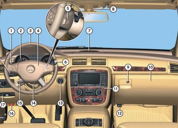
1 Front left reading lamp, on/off 2 Rear interior lighting, on/off 3 Automatic interior lighting 4 Front interior lighting, on/off 5 Front right reading lamp, on/off 6 Front right interior lamp 7 Reading lamps 8 Front left interior lamp
The controls are located in the overhead control panel.
! An interior lamp switched on manually does not go out automatically. Leaving an interior lamp switch in the ON position for extended periods of time with the engine turned off could result in a discharged battery.
Activating automatic control 왘 Press switch 3.
The interior lighting and the locator lighting (컄 page 178) come on when you 앫 unlock the vehicle 앫 remove the SmartKey from the
starter switch
앫 open a door 앫 open the tailgate
The interior lighting switches off after 10 seconds see “Setting interior lighting delayed shut-off” (컄 page 180).
i If a door remains open, the interior lighting switches off automatically after approximately 5 minutes.
Deactivating automatic control
i The interior lighting is factory-set to automatic mode. 왘 Press switch 3.
The interior lighting and the locator lighting (컄 page 178) remain switched off even when you 앫 unlock the vehicle 앫 remove the SmartKey from the
starter switch
앫 open a door 앫 open the tailgate
Controls in detail Lighting
Manual control
Switching front/rear interior lighting on and off 왘 Press front/rear interior lighting
switch 4 or 2 (컄 page 150) to switch on the desired interior light.
왘 Press front/rear interior lighting
switch 4 or 2 again to switch off the respective interior light.
Switching front reading lamps on and off The front reading lamps are located in the lower edge of the interior rear view mirror. 왘 Press front reading lamp
switch 1 or 5 (컄 page 150) to switch on the desired front reading lamp.
왘 Press front reading lamp
switch 1 or 5 again to switch off the respective front reading lamp.
151
Controls in detail Lighting
Switching second-row reading lamps on and off The second row reading lamps are located above the side windows.
Switching third-row reading lamps* on and off The switches for the third-row reading lamps are located in the rear overhead control panel.
왘 Press rear reading lamp
switch 1 or 2 to switch on the respective rear reading lamp.
왘 Press rear reading lamp
switch 1 or 2 again to switch off the respective rear reading lamp.
i The rear interior lighting is switched on and off using the switch on the front overhead control panel (컄 page 150).
Passenger side reading lamp 1 Second-row reading lamp 왘 Press on reading lamp 1 where indi-
cated by arrow. The reading lamp comes on.
왘 Press on reading lamp 1 once more.
The reading lamp goes out.
1 Rear right reading lamp, on/off 2 Rear left reading lamp, on/off 3 Rear left reading lamp 4 Rear interior lamp 5 Rear right reading lamp
152
Door entry lamps
Cargo compartment lamp
For better orientation in the dark, the corresponding door entry lamps will switch on in darkness when you open a door and the automatic control is activated. The door entry lamps will switch off when the corresponding door is closed.
i If you turn the SmartKey in the starter switch to position 0 and switch off the headlamps, the door entry lamps will remain lit for approximately 5 minutes.
The cargo compartment lamp comes on when the tailgate is opened. If you leave the tailgate open for an extended period of time, the cargo compartment lamp will switch off automatically after approximately 10 minutes.
Controls in detail Lighting
153
Controls in detail Instrument cluster
For a full view illustration of the instrument cluster, see “Instrument cluster” (컄 page 26).
1 To dim instrument cluster illumination 2 Reset button 3 To brighten instrument cluster
illumination
The instrument cluster is activated when you 앫 open a door 앫 switch on the ignition (컄 page 39) 앫 press reset button 2
앫 switch on the exterior lamps(컄 page 143)
154
i Opening a front door or pressing the reset button without switching on the ignition or the exterior lighting activates the multifunction display illumination only for 30 seconds.
For information on changing the instru- ment cluster settings, e.g. the language, see “Instrument cluster submenu” (컄 page 174).
Warning!
Adjusting instrument cluster illumination
Use button 1 or 3 to adjust the illumina- tion brightness for the instrument cluster.
i The instrument cluster illumination is dimmed or brightened automatically to suit ambient light conditions. The instrument cluster illumination will also be adjusted automatically when you switch on the vehicle’s exterior lamps.
No messages will be displayed if either the instrument cluster or the multifunction display is inoperative.
i With the exterior lighting switched on, the brightness of the switches in the center console will also be adjusted when using button 1 or 3.
As a result, you will not be able to see information about your driving conditions, such as speed or outside temperature, warning/indicator lamps, malfunction/warning messages or the failure of any systems. Driving characteris- tics may be impaired.
If you must continue to drive, do so with added caution. Contact an authorized Mercedes-Benz Light Truck Center as soon as possible.
To brighten illumination 왘 Press and hold button 3 until the
desired level of illumination is reached.
To dim illumination 왘 Press and hold button 1 until the
desired level of illumination is reached.
Controls in detail Instrument cluster
Resetting trip odometer
Tachometer
Outside temperature indicator
Make sure you are viewing the trip odometer display (컄 page 157). 왘 If it is not displayed, press button è or ÿ on the multifunction steering wheel (컄 page 158) repeatedly until the trip odometer appears in the multi- function display.
왘 Press and hold reset button 2
(컄 page 154) until the trip odometer is reset.
The red marking on the tachometer (컄 page 29) denotes excessive engine speed.
! Avoid driving at excessive engine speeds, as it may result in serious engine damage that is not covered by the Mercedes-Benz Limited Warranty.
To help protect the engine, the fuel supply is interrupted if the engine is operated within the red marking.
Warning!
The outside temperature indicator is not designed to serve as an ice-warning device and is therefore unsuitable for that purpose.
Indicated temperatures just above the freezing point do not guarantee that the road surface is free of ice. The road may still be icy, especially in wooded areas or on bridges.
The outside temperature is indicated in the multifunction display (컄 page 157).
155
Controls in detail Instrument cluster
The outside temperature sensor is located in the front bumper area. Due to its loca- tion, the sensor can be affected by road or engine heat during idling or slow driving. This means that the accuracy of the dis- played temperature can only be verified by comparison to a thermometer placed next to the sensor, not by comparison to exter- nal displays (e.g. bank signs etc.). When moving the vehicle into colder ambient temperatures (e.g. when leaving your garage), you will notice a delay before the lower temperature is displayed. A delay also occurs when ambient temper- atures rise. This prevents inaccurate temperature indications caused by heat radiated from the engine during idling or slow driving.
156
왔 Control system The control system is activated as soon as the SmartKey in the starter switch is turned to position 1 (컄 page 40) or as soon as the KEYLESS-GO start/stop button* is in position 1 (컄 page 41). The control system enables you to 앫 call up information about your vehicle 앫 change vehicle settings For example, you can use the control system to find out when your vehicle is next due for maintenance service, to set the language for messages in the instru- ment cluster display, and much more.
Controls in detail Control system
Warning!
Multifunction display
A driver’s attention to the road and traffic conditions must always be his/her primary focus when driving.
For your safety and the safety of others, selecting features through the multifunction steering wheel should only be done by the driver when traffic and road conditions permit it to be done safely.
Bear in mind that at a speed of just 30 mph (approximately 50 km/h), your vehicle is covering a distance of 44 feet (approximately 14 m) every second.
The control system relays information to the multifunction display.
1 Trip odometer 2 Main odometer 3 Transmission position indicator 4 Current transmission program mode 5 Status indicator (outside temperature
or digital speedometer)
For more information on menus displayed in the multifunction display, see “Menus” (컄 page 160).
157
Controls in detail Control system
Multifunction steering wheel
The displays in the multifunction display and the settings in the control system are controlled by the buttons on the multifunc- tion steering wheel.
158
1 Multifunction display
5 Menu systems:
Press button è for next menu ÿ for previous menu
6 ! Voice Control System* on1,
see separate operating instructions
7 0 Voice Control System* off1,
see separate operating instructions
1 Vehicles without Voice Control System*: Button
without function.
Operating the control system
2 Selecting the submenu or setting
the volume: Press button æ up/to increase ç down/to decrease
3 Telephone*: Press button s to take a call
to dial to redial
t to end a call
to reject an incoming call
4 Moving within a menu:
Press button j for next display k for previous display
Controls in detail Control system
Depending on the selected menu, pressing the buttons on the multifunction steering wheel will alter what appears in the multi- function display. The information available in the multifunc- tion display is arranged in menus, each containing a number of functions or sub- menus. The individual functions are then found within the relevant menu (radio or CD operations under AUDIO, for example). These functions serve to call up relevant information or to customize the settings for your vehicle.
It is helpful to think of the menus, and the functions within each menu, as being ar- ranged in a circular pattern. 앫 If you press button è or ÿ
repeatedly, you will pass through each menu one after the other.
앫 If you press button k or j
repeatedly, you will pass through each function display, one after the other, in the current menu.
In the Settings menu, instead of functions, you will find a number of submenus for calling up and changing settings. For instructions on using these submenus, see “Settings menu” (컄 page 170). The number of menus available in the system depends on which optional equip- ment is installed in your vehicle. The menus are described on the following pages.
159
Controls in detail Control system
Menus
This is what you will see when you scroll through the menus 1 to 5.
The table on the next page provides an overview of the individual menus.
160
Controls in detail Control system
Menu 3
NAV* (컄 page 167) Route guidance instructions, current direction traveledMenu 5
Menu 4
AIRMATIC*/Compass DISTRONIC* (컄 page 262) (컄 page 168) AIRMATIC* Status and settingsSelecting satellite radio station* Operating CD player
Compass
Menus, submenus and functions
Menu 1
Standard display (컄 page 164) Trip- and main odometer Selecting radio stationMenu 2
AUDIO (컄 page 165)Checking tire inflation pressure Checking coolant temperature
Calling up digital speedometer or outside temperature Calling up maintenance service indicator
i The headings used in the menus table are designed to facilitate navigation within the
system and are not necessarily identical to those shown in the control system displays. The first
function displayed in each menu will automati- cally show you which part of the system you are in.
161
Controls in detail Control system
This is what you will see when you scroll through the menus 6 to a.
The table on the next page provides an overview of the individual menus.
162
Menus, submenus and functions
Menu 6
Vehicle status message memory1
(컄 page 169) Calling up malfunction mes- sages, warning messages, and system status messages stored in memoryMenu 7
SettingsMenu 8
Distance warning function* (컄 page 185)(컄 page 170) Resetting to factory settings Distance warning function* on/off
Instrument cluster submenu
Time/Date submenu
Lighting submenu Vehicle submenu Comfort submenu*