- Download PDF Manual
-
RPad sharp edges for protection.
342 Stowage areas
Cargo compartment
Cargo compartment cover
Important safety notes
G WARNING On its own, the cargo compartment cover cannot secure or restrain heavy objects, items of luggage and heavy loads. You could be hit by an unsecured load during sudden changes in direction, braking or in the event of an accident. There is an increased risk of injury or even fatal injury.
Always store objects so that they cannot be flung around. Secure objects, luggage or loads against slipping or tipping over, e.g. by using tie downs, even if you are using the cargo compartment cover.
! When loading the vehicle, make sure that
you do not stack the load in the cargo compartment higher than the lower edge of the side windows. Do not place heavy objects on top of the cargo compartment cover.
The cargo compartment cover may be installed behind the 2nd or 3rd row of seats.
Extending/retracting the cargo
compartment cover
There are four cargo tie-down rings : in the cargo compartment.
Bag hook
G WARNING The bag hooks cannot restrain heavy objects or items of luggage. Objects or items of luggage could be flung around and thereby hit vehicle occupants when braking or abruptly changing directions. There is a risk of injury.
Only hang light objects on the bag hooks. Never hang hard, sharp-edged or fragile objects on the bag hooks.
! The bag hook can bear a maximum load of 6.6lbs (3kg) and should not be used to secure a load.
There is a bag hook in the cargo compartment on the right-hand side.
X Press bag hook marking :.
X Turn bag hook : until it engages.
Stowage areas
343
The TIREFIT kit, tire-change tool kit, etc. are located in the stowage compartment.
X To open: holding the ribbing, press
handle : downwards ;. Handle : folds up.
X Swing the cargo compartment floor
upwards using handle : until it rests against the cargo compartment cover.
X Fold out hook = on the underside of the
cargo compartment floor in the direction of the arrow.
X To extend: pull the cargo compartment cover back by grab handle : and clip it into retainers ; on the left and right.
X To retract: unhook the cargo compartment
cover from left-hand and right-hand retainers ;.
X Guide cargo compartment cover forwards
by grab handle : until it is completely rolled up.
Coat hooks on the tailgate
: Coat hook
Stowage well under the cargo
compartment floor
G WARNING If you drive when the cargo compartment floor is open, objects could be flung around, thus striking vehicle occupants. There is a risk of injury, particularly in the event of sudden braking or a sudden change in direction.
Always close the cargo compartment floor before a journey.
344 Features
X Attach hook = to the cargo
compartment's upper seal ?.
X To close: detach hook = from the cargo
compartment's upper seal ?.
X Fasten hook = to the bracket on the
underside of the cargo compartment floor.
X Fold the trunk floor down.
X Press the cargo compartment floor
down ; until it engages.
Position the load on the roof carrier in such a way that the vehicle will not sustain damage even when it is in motion.
Depending on the vehicle equipment, ensure that when the roof carrier is installed you can:
Rraise the sliding sunroof fully
Ropen the panorama roof with power tilt/
sliding panel fully
Ropen the tailgate fully
The maximum roof load is 220 lbs(100 kg).
Attaching the roof carrier
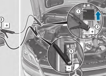
1 Cargo compartment floor unlocked
2 Cargo compartment floor locked
The cargo compartment floor can be locked and unlocked using the mechanical key.
Roof carrier
Important safety notes
G WARNING When you load the roof, the center of gravity of the vehicle rises and the driving characteristics change. If you exceed the maximum roof load, the driving characteristics, as well as steering and braking, will be greatly impaired. There is a risk of an accident.
Never exceed the maximum roof load and adjust your driving style.
! Mercedes-Benz recommends that you
only use roof carriers that have been tested and approved for Mercedes-Benz vehicles. This helps to prevent damage to the vehicle.
X Secure the roof carrier to roof rails :. In
doing so, observe the manufacturer's installation instructions.
Features
Cup holder
Important safety notes
G WARNING If objects in the passenger compartment are stowed incorrectly, they can slide or be thrown around and hit vehicle occupants. There is a risk of injury, particularly in the event of sudden braking or a sudden change in direction.
RAlways stow objects so that they cannot be
Temperature-controlled cup holder in
thrown around in such situations.
the front-compartment center console
Features
345
RAlways make sure that objects do not
protrude from stowage spaces, parcel nets or stowage nets.
RClose the lockable stowage spaces while
driving.
RStow and secure objects that are heavy, hard, pointy, sharp-edged, fragile or too large in the cargo compartment.
! Only use the cup holders for containers of
the right size and which have lids. The drinks could otherwise spill.
The stowage compartments in the doors provide space for bottles with a capacity of up to 34 fl. oz. (1.0 liter).
The bottles are not secured or prevented from tipping over. Therefore, do not place any open drink containers in the stowage compartments.
Cup holder in the front-compartment
center console
: Cup holder
; Cover
X To open: slide cover ; to its foremost
position.
X To close: pull cover ; back as far as it will
go.
You can remove the cup holder's rubber mat for cleaning. Clean with clear, lukewarm water only.
: Cup holder
; Residual heat indicator lamp
= Switch
The temperature-controlled cup holder can be used to keep cold drinks cool and warm drinks warm.
X Turn the SmartKey to position 2 in the
ignition lock.
X To switch on the cooling function: press and hold button = until the blue indicator lamp on the button lights up.
X To switch on the heating function: press and hold button = until the red indicator lamp on the button lights up.
X To switch off the function: press and hold
button = until the indicator lamp on the button goes out.
When the heating function is used, the metal insert of the cup holder is heated. Once a certain temperature is reached, residual heat indicator lamp ; lights up. This means that the metal insert of the cup holder is hot. For this reason, you must not reach into the cup holder metal insert.
Do not use hard or sharp objects to clean the cup holder. Use only a soft cloth to clean it.
Cup holder in the rear seat armrest
! Do not sit on or support your body weight on the rear seat armrest when it is folded down, as you could otherwise damage it.
346 Features
X Fold down the rear seat armrest.
Cup holder : is located in the rear seat armrest.
: Mirror light
; Bracket
= Retaining clip, e.g. for a car park ticket
Cup holder in the third row of seats
? Vanity mirror
A Mirror cover
Vanity mirror in the sun visor
Mirror light : only functions if the sun visor is clipped into bracket ; and mirror cover A has been folded up.
Glare from the side
: Cup holder
The cup holders are located in the side trim on the left and right-hand sides.
Sun visors
Overview
G WARNING If the mirror cover of the vanity mirror is folded up when the vehicle is in motion, you could be blinded by incident light. There is a risk of an accident.
Always keep the mirror cover folded down while driving.
X Fold down sun visor :.
X Pull sun visor : out of retainer =.
X Swing sun visor : to the side.
X Slide sun visor : horizontally as required.
X Fold down additional sun visor ; to the
windshield.
Features
347
Roller sunblinds on the rear side
X Tilt pull-out profile : as illustrated.
windows
X Slip guide bush ; into open area of guide
! Always guide the roller sunblind by hand.
rail =.
Do not let it snap back suddenly as this would damage the automatic roller mechanism.
X Straighten up pull-out profile : again.
! Do not drive the vehicle with the roller
Ashtray
sunblind hooked in and the side windows opened simultaneously. The roller sunblind can jump out of the retainers and spring back suddenly when driving at high speeds, e.g. when driving on the freeway. This could damage the inertia reel. Therefore, either close the side window or retract the roller sunblind before driving at high speeds.
Front ashtray
! The holder under the ashtray is not heat resistant. Before placing lit cigarettes in the ashtray, make sure that the ashtray is properly engaged. Otherwise, the holder could be damaged.
X To extend: pull the roller sunblind out by
tab : and hook it onto retainers ; at the back of the window.
The roller sunblind can be hooked back into place should it pop out from the top of the guide rail.
X To open: slide cover : to its foremost
position.
X Fold cover = of the insert upwards.
X To remove the insert: push insert = to
the left ?. Insert = slides out slightly to the right.
X Lift insert = up ; and out.
X To re-install the insert: place insert = into the holder and press it down on the right until it engages.
X To close: pull cover : back as far as it will
go.
Rear-compartment ashtray
! Close the ashtray when it is not in use and before you fold the rear seats forward. You can otherwise damage the ashtray.
348 Features
X To open: briefly press cover ; at the top.
The ashtray opens.
X To remove the insert: push into recess
= from the right. Ashtray insert : slides out slightly to the right.
X Lift insert : up and out.
X To re-install the insert: place insert :
into the holder and press down on the right until it engages.
Vehicles without a Rear Seat Entertainment System have an ashtray in the center console in the rear compartment.
Your attention must always be focused on the traffic conditions. Only use the cigarette lighter when road and traffic conditions permit.
X Turn the SmartKey to position 2 in the
ignition lock (Y page 163).
X To open: slide cover : to its foremost
position.
X Press in cigarette lighter ;.
Cigarette lighter ; will pop out automatically when the heating element is red-hot.
X To close: pull cover : back as far as it will
go.
Cigarette lighter
G WARNING You can burn yourself if you touch the hot heating element or the socket of the cigarette lighter.
In addition, flammable materials can ignite if:
Rthe hot cigarette lighter falls
Ra child holds the hot cigarette lighter to
objects, for example
There is a risk of fire and injury.
Always hold the cigarette lighter by the knob. Always make sure that the cigarette lighter is out of reach of children. Never leave children unsupervised in the vehicle.
! The cigarette lighter in the center console
in the front compartment is not intended for operating the tire inflation compressor.
12 V sockets
General notes
X Turn the SmartKey to position 1 in the
ignition lock (Y page 163).
With the exception of the socket in the front center console, all sockets can be used for accessories with a maximum current draw of 240 W (20 A). The socket in the front center console can be used for accessories with a maximum current draw of 180 W (15 A). Accessories include such items as lamps or chargers for mobile phones.
If you use the sockets for long periods when the engine is switched off, the battery may discharge.
i An emergency cut-out ensures that the
on-board voltage does not drop too low. If
the on-board voltage is too low, the power to the sockets is automatically cut. This ensures that there is sufficient power to start the engine.
Socket in the front-compartment center
console
! The socket is not suitable for operating
the tire inflation compressor.
X To open: slide cover : to its foremost
position.
X Lift up the cover of socket ;.
X To close: pull cover : back as far as it will
go.
Socket in the rear-compartment center
console
X Lift up the cover of socket :.
Vehicles with the Rear Seat Entertainment System have two sockets in the center console in the rear compartment.
Features
349
Socket in the cargo compartment
X Lift up the cover of socket :.
115 V socket
Important safety notes
G DANGER When a suitable device is connected, the 115 V power socket will be carrying a high voltage. You could receive an electric shock if the connector cable or the 115 V power socket is pulled out of the trim or is damaged or wet. There is a risk of fatal injury.
RUse only connector cables that are dry and
free of damage.
RWhen the ignition is off, make sure that the
115 V power socket is dry.
RHave the 115 V power socket checked or
replaced immediately at a qualified specialized workshop if it is damaged or has been pulled out of the trim.
RNever plug the connector cable into a
115 V power socket that is damaged or has been pulled out of the trim.
G DANGER If you reach into the power socket or plug inappropriate devices into the power socket, you could receive an electric shock. There is a risk of fatal injury.
Only connect appropriate devices to the power socket.
350 Features
! Note that work and repairs on the 115 V power socket should only be carried out by qualified specialist personnel.
X Insert the plug of the electronic device into
115 V power socket :. Indicator lamp ; lights up.
X To turn off: disconnect the plug from
115 V power socket :.
Ensure that you do not pull on the cord.
General notes
115 V power socket provides an alternating voltage of 115 V so that small electronic devices can be connected. These devices, such as games consoles, chargers and laptops, should not consume more than a maximum of 150 watts altogether.
Requirements for operation of these devices:
Rthe electronic device that you connect has
a suitable connector and conforms to standards specific to the country you are in.
Rthe plug of the electronic device is plugged
correctly into 115 V power socket.
Rthe maximum wattage of the device to be
connected must not exceed 150 watts.
Rthe on-board power supply is within a
permissible voltage range.
Rthe 12 V sockets in the rear compartment
and the cargo compartment are operational.
Using the 115 V power socket
X To switch on: switch the ignition on.
X Open flap =.
Problems with the 115 V power socket
Problem
Possible causes/consequences and M Solutions
Features
351
The warning lamp on the 115 V power socket is not lit.
The on-board voltage is too low because the battery is too weak.
X Start the engine.
or
X Charge the battery (Y page 390).
If the indicator lamp still does not light up:
X Visit a qualified specialist workshop.
The temperature of the DC/AC converter is temporarily too high.
X Remove the electronic device connector from the 115 V socket.
X Let the DC/AC converter cool down.
If the indicator lamp still does not light up after cooling down the converter:
X Visit a qualified specialist workshop.
You have connected an electronic device that has a constant nominal power of less than 150 watts, but a very high switch-on current. This device will not work. If you connect such a device, the 115 V power socket will not supply it with power.
X Connect a suitable device.
mbrace
Important safety notes
! You must have a license agreement to activate the mbrace service. Make sure that your system is activated and ready for use. To register, press theï MB Info call button. If any of the steps mentioned are not carried out, the system may not be activated.
If you have questions about the activation, contact one of the following telephone hotlines:
RUSA: Mercedes-Benz Customer
Assistance Center at 1-800-FOR-MERCedes (1-800-367-6372) or 1-866-990-9007
Shortly after successfully registering with the mbrace service (Canada: TELEAID), a user ID and password will be sent to you by post. USA only: you can use this password to log onto the mbrace area under "Owners Online" at http://www.mbusa.com.
The mbrace system is available if:
Rit has been activated and is operational
Rthe corresponding mobile phone network
is available for transmitting data to the Customer Center
Ra service subscription is available
Rthe starter battery is sufficiently charged
i Determining the location of the vehicle on
a map is only possible if:
RGPS reception is available.
RCanada: Customer Service at
Rthe vehicle position can be forwarded to
1-888-923-8367
the Customer Assistance Center.
352 Features
The mbrace system
To adjust the volume during an mbrace call, proceed as follows:
X Press the W or X button on the
multifunction steering wheel.
or
X Use the volume controller of the audio
system/COMAND.
The mbrace system provides various services, e.g.:
Rautomatic and manual emergency call
RRoadside Assistance call
RMB Info call
USA only: you can find information and a description of all available features under "Owners Online" at http://www.mbusa.com.
System self-test
After you have switched on the ignition, the system carries out a self-diagnosis.
A malfunction in the system has been detected if one of the following occurs:
RThe indicator lamp in the SOS button does
not come on during the system self-test. RThe indicator lamp in the F Roadside
Assistance button does not light up during self-diagnosis of the system.
RThe indicator lamp in theï MB Info call
button does not light up during self- diagnosis of the system.
RThe indicator lamp in one or more of the
following buttons continues to light up red after the system self-diagnosis:
- SOS button
the F Roadside Assistance call button the ï MB Info call button
If a malfunction is indicated as outlined above, the system may not operate as expected. In the event of an emergency, help will have to be summoned by other means.
Have the system checked at the nearest authorized Mercedes-Benz Center or contact the following service hotlines:
RUSA: Mercedes-Benz Customer Assistance
Center at 1-800-FOR-MERCedes (1-800-367-6372) or 1-866-990-9007
RCanada: Customer Service at
1-888-923-8367
Emergency call
Important safety notes ! You must have a license agreement to activate the mbrace service. Make sure that your system is activated and ready for use. To register, press theï MB Info call button. If any of the steps mentioned are not carried out, the system may not be activated.
If you have questions about the activation, contact one of the following telephone hotlines:
RUSA: Mercedes-Benz Customer
Assistance Center at 1-800-FOR-MERCedes (1-800-367-6372) or 1-866-990-9007
RCanada: Customer Service at
1-888-923-8367
General notes
An emergency call is dialed automatically if an air bag or Emergency Tensioning Device is triggered.
i You cannot end an automatically triggered emergency call yourself.
RThe mbrace Inoperative or mbrace
Service Not Activated message appears in the multifunction display after the system self-diagnosis.
An emergency call can also be initiated manually.
As soon as the emergency call has been initiated, the indicator lamp in the SOS button
flashes. The Connecting Call message appears in the multifunction display.
The audio output is muted.
Once the connection has been made, the Call Connected message appears in the multifunction display.
All important information on the emergency is transmitted, for example:
RCurrent location of the vehicle (as
determined by the GPS system)
RVehicle identification number
RInformation on the severity of the accident
Shortly after the emergency call has been initiated, a voice connection is automatically established between the Mercedes-Benz Customer Assistance Center and the vehicle occupants.
RIf the vehicle occupants respond, the Mercedes-Benz Customer Assistance Center attempts to get more information on the emergency.
RIf there is no response from the vehicle
occupants, an ambulance is immediately sent to the vehicle.
The mbrace system has not been able to initiate an emergency call if no voice connection to the Response Center has been established. This can occur, for example, if the relevant mobile phone network is not available. The indicator lamp in the SOS button flashes continuously.
The Call Failed message appears in the multifunction display and must be confirmed.
In this case, seek assistance by other means.
Features
353
Making an emergency call
G WARNING It can be dangerous to remain in the vehicle, even if you have pressed the SOS button in an emergency if:
Ryou see smoke inside or outside of the
vehicle, e.g. if there is a fire after an accident
Rthe vehicle is on a dangerous section of
road
Rthe vehicle is not visible or cannot easily be seen by other road users, particularly when dark or in poor visibility conditions
There is a risk of an accident and injury.
Leave the vehicle immediately in this or similar situations as soon as it is safe to do so. Move to a safe location along with other vehicle occupants. In such situations, secure the vehicle in accordance with national regulations, e. g. with a warning triangle.
X To initiate an emergency call
manually: press cover : briefly to open.
X Press SOS button ; briefly.
The indicator lamp in SOS button ; flashes until the emergency call is concluded.
X Wait for a voice connection to the
Mercedes-Benz Customer Assistance Center.
X After the emergency call, close cover :.
i If the mobile phone network is not
available, mbrace is not able to make an emergency call. If you leave the vehicle
Assistance center can ascertain the nature of the problem (Y page 358).
The Mercedes-Benz Customer Assistance Center either sends a qualified Mercedes- Benz technician or arranges for your vehicle to be transported to the nearest authorized Mercedes-Benz Center. You may be charged for services such as repair work and/or towing. Further details are available in your mbrace manual.
i The mbrace system failed to initiate a
Roadside Assistance call if:
Rthe indicator lamp for Roadside
Assistance call button : is flashing continuously.
Rno voice connection to the Mercedes- Benz Customer Assistance Center was established.
This may be because the corresponding mobile phone network is not available.
The Call Failed message appears in the multifunction display.
X To end a call: press the~ button on the
multifunction steering wheel.
or
X Press the corresponding button for ending
a phone call on the audio system or on COMAND.
MB Info call button
354 Features
immediately after pressing the SOS button, you do not know if mbrace has successfully made the emergency call. In this situation, seek additional assistance by other means.
Roadside Assistance button
X Press Roadside Assistance button :.
This initiates a call to the Mercedes-Benz Customer Assistance Center. The indicator lamp in Roadside Assistance button : flashes while the call is active. The Connecting Call message appears on the multifunction display. The audio output is muted.
If a connection can be made, the Call Connected message appears in the multifunction display.
If a cellular phone network is available and there is sufficient GPS reception, the mbrace system transmits data to the Mercedes-Benz Customer Assistance Center, for example:
RCurrent location of the vehicle
RVehicle identification number
i The display of the audio system or
COMAND shows that an mbrace call is active. During the call, you can change to the navigation menu by pressing the NAVI button on COMAND, for example.
Voice output is not available.
A voice connection is established between the Mercedes-Benz Customer Assistance Center and the vehicle occupants.
From the vehicle remote malfunction diagnosis, the Mercedes-Benz Customer
Features
355
X Press MB Info call button :.
This initiates a call to the Mercedes-Benz Customer Assistance Center. The indicator lamp in MB Info call button : flashes while the connection is being made. The Connecting Call message appears on the multifunction display. The audio system is muted.
If a connection can be made, the Call Connected message appears in the multifunction display.
If a cellular phone network is available and there is sufficient GPS reception, the mbrace system transmits data to the Mercedes-Benz Customer Assistance Center, for example:
RCurrent location of the vehicle
RVehicle identification number
i The display of the audio system or
COMAND shows that an mbrace call is active. During the call, you can change to the navigation menu by pressing the NAVI button on COMAND, for example.
Voice output is not available.
A voice connection is established between the Mercedes-Benz Customer Assistance Center and the vehicle occupants. You can obtain information on how to operate your vehicle's systems, on the location of the nearest authorized Mercedes-Benz Center, and on further products and services offered by Mercedes-Benz USA.
USA only: you can find further information on the mbrace system under "Owners Online" at http://www.mbusa.com.
The Call Failed message appears in the multifunction display.
X To end a call: press the~ button on the
multifunction steering wheel.
or
X Press the corresponding button for ending
a phone call on the audio system or on COMAND.
Call priority
When service calls are active, e.g. Roadside Assistance or MB Info calls, an emergency call can still be initiated. In this case, an emergency call will take priority and override all other active calls.
The indicator lamp of the respective button flashes until the call is ended. An emergency call can only be terminated by the Mercedes- Benz Customer Assistance Center.
All other calls can be ended by pressing:
Rthe ~ button on the multifunction
steering wheel
Rthe corresponding button on the audio
system or on COMAND for ending a telephone call
i If an mbrace call is initiated, audio output
is muted. The mobile phone is no longer connected to COMAND. However, if you would like to use your mobile phone, do so only when the vehicle is stationary and in a safe location.
Downloading destinations in COMAND
i The mbrace system failed to initiate an
Downloading destinations
MB Info call if:
Rthe indicator lamp in MB Info call
button : is flashing continuously.
Rno voice connection to the Mercedes- Benz Customer Assistance Center was established.
This may be because the corresponding mobile phone network is not available.
Destination Download gives you access to a data bank with over 15 million Points of Interest (POIs). These can be downloaded on the navigation system in your vehicle. If you know the destination, the address can be downloaded. Alternatively, you can obtain the location of Points of Interest (POIs)/ important destinations in the vicinity.
356 Features
Furthermore, you can download routes with up to 20 way points.
mbrace directly to your vehicle's navigation system.
You are prompted to confirm route guidance to the address entered.
The system calculates the route and subsequently starts the route guidance with the address entered.
Specifying and sending the destination
address
X Go to the website http://
www.maps.google.com and enter a destination address into the entry field.
i If you select No, the address can be stored
X To send the destination address to the
in the address book.
i The Destination Download function is
available if the corresponding mobile phone network is available and data transfer is possible.
i You can only use the Destination Download function if the vehicle is equipped with a navigation system.
Route Assistance
This service is part of the mbrace PLUS Package and cannot be purchased separately.
i You can also use the Route Assistance
function if your vehicle is not equipped with a navigation system.
Within the framework of this service, you receive a professional and reliable form of navigation support without having to leave your vehicle.
The customer service representative finds a suitable route depending on your vehicle's current position and the desired destination. You will then be guided live through the current route section.
Search & Send
General notes i To use "Search & Send", your vehicle
must be equipped with mbrace and a navigation system. You must also have an mbrace service subscription.
"Search & Send" is a destination entry service. A destination address which is found on Google Maps® can be transferred via
e-mail address of your mbrace account: click on the corresponding button.
i Example:
If you select 'Send to vehicle' and then 'Mercedes-Benz', the destination address will be sent to your vehicle.
X When the "Send" dialog window appears:
In the relevant field, enter the e-mail address which you specified when activating your mbrace account.
X Click "Send".
i Information on specific commands such
as "Address entry" or "Sending" can be found on the website.
Calling up destination addresses
X Switch on the ignition.
The destination address is loaded into the vehicle's navigation system.
A display message appears, asking whether navigation should be started. X Select Yes by sliding XVY and turning
cVd the COMAND controller and press W to confirm. The system calculates the route and subsequently starts the route guidance with the address entered.
i If you select No, the address can be stored
in the address book.
i If you have sent more than one
destination address, each individual destination must be confirmed separately.
i Destination addresses are loaded in the same order as the order in which they were
Features
357
sent. If you have multiple Mercedes-Benz vehicles with mbrace and active mbrace accounts:
if multiple vehicles are registered under the same e-mail address, the destination will be sent to all the vehicles.
Vehicle remote opening
You can use the vehicle remote opening if you have unintentionally locked your vehicle and a replacement SmartKey is not available. The vehicle can be opened by the Mercedes-Benz Customer Assistance Center.
The vehicle can be immediately opened remotely within four days of the ignition being turned off. After this time, the remote opening may be delayed by 15 to 60 minutes. After 30 days the vehicle can no longer be opened remotely.
Vehicle remote closing
The remote closing feature can be used when you have forgotten to lock the vehicle and you are no longer nearby. The vehicle can then be locked by the Mercedes-Benz Customer Assistance Center.
The vehicle can be immediately remotely locked within four days of the ignition being turned off. After this time, the remote closing may be delayed by 15 to 60 minutes. After 30 days the vehicle can no longer be closed remotely.
X Contact the following service hotlines:
RUSA: Mercedes-Benz Customer
Assistance Center at 1-800-FOR-MERCedes (1-800-367-6372) or 1-866-990-9007
RCanada: Customer Service at
1-888-923-8367
X Contact the following service hotlines:
You will be asked for your PIN.
RUSA: Mercedes-Benz Customer
Assistance Center at 1-800-FOR-MERCedes (1-800-367-6372) or 1-866-990-9007
RCanada: Customer Service at
1-888-923-8367
You will be asked for your password.
X Return to your vehicle at the time agreed upon with the Mercedes-Benz Customer Assistance Center.
USA only: alternatively, the vehicle can be opened via:
Rthe Internet, under the "Owners Online"
section
Rthe telephone application (e.g. iPhone®,
Blackberry)
To do this, you will need your identification number and password.
i Vehicle remote opening is only possible if the corresponding mobile phone network is accessible.
The next time you are inside the vehicle and you switch on the ignition, the Doors Locked Remotely message appears in the multifunction display.
USA only: alternatively, the vehicle can be locked via:
Rthe Internet, under the "Owners Online"
section
Rthe telephone application (e.g. iPhone®,
Blackberry)
To do this, you will need your identification number and password.
i The vehicle remote closing feature is
available when the relevant mobile phone network is available and data connection is possible.
358 Features
Stolen vehicle recovery service
X Press Yes to confirm the message.
If your vehicle has been stolen:
X Notify the police.
The police will issue a numbered incident report.
X This number will be forwarded to the Mercedes-Benz Customer Assistance Center together with your PIN. The Mercedes-Benz Customer Assistance Center then attempts to locate the mbrace system. The Mercedes-Benz Customer Assistance Center contacts you and the local law enforcement agency if the vehicle is located. However, only the law enforcement agency is informed of the location of the vehicle.
i If the anti-theft alarm system is activated for longer than 30 seconds, the Mercedes- Benz Customer Assistance center is automatically informed.
Vehicle remote malfunction diagnosis
With the vehicle remote malfunction diagnosis (Vehicle Health Check), the Customer Assistance center can provide improved support for problems with your vehicle. During an existing call, vehicle data is transferred to the Customer Assistance center. The customer service representative can use the received data to decide what kind of assistance is required. You are then, for example, guided to the nearest Mercedes- Benz Service center or a recovery vehicle is called.
If vehicle data needs to be transferred during an MB Info call or a Roadside Assistance call, this is initiated by the Customer Assistance center. You will see the Roadside Assistance Connected message in the COMAND display. If the vehicle remote malfunction diagnosis is able to be started, the Request for vehicle diagnosis received. Start vehicle diagnosis? message appears in the display.
X If the Vehicle Diagnosis: Please
switch on ignition. message appears: turn the key to position 2 in the ignition lock.
X If the Please follow the
instructions received by phone and move your vehicle to a safe position. message appears: follow the instructions of the customer service representative. The message in the display disappears.
If you select Cancel, the vehicle remote malfunction diagnosis is canceled completely.
The vehicle operating state check begins. Meanwhile, the Vehicle diagnosis activated message appears.
When the check is finished, the Sending vehicle diagnosis data...(Voice connection may be interrupted during data transfer.) message appears. The vehicle data can now be sent to the Customer Assistance center.
X Press OK to confirm the message.
The voice connection with the Customer Assistance center is terminated.
The Vehicle Diagnosis: Transferring data... appears.
The vehicle data is sent to the Customer Assistance center.
Depending on what the customer service representative agreed with you, the voice connection is re-established after the transfer is complete. If necessary, you will be contacted at a later time by another means, e.g. by E-Mail or telephone.
Further functions of the vehicle remote malfunction diagnosis include, for example:
Rtransfer of service data to the Customer
Assistance center. If a service is overdue, the COMAND display shows a message
Features
359
about various special offers at your workshop.
Rmonthly status information E-Mail on oil level, air pressure, maintenance, brakes, etc. If applicable, you will receive information on special offers in the E-Mail.
USA only: this information can also be called up under "Owners Online" at http:// www.mbusa.com.
Information on the data stored in the vehicle (Y page 29).
Information on roadside assistance (Y page 25).
Speed alert
You can define the upper speed limit, which must not be exceeded by the vehicle. If this selected speed is exceeded by the vehicle, a message will be sent to the Customer Assistance center. The Customer Assistance center then forwards this information to you. You can select the way in which you receive this information beforehand. Possible options include SMS, E-Mail or an automated call.
The data which is sent to the Customer Assistance center contains the following information:
Rthe location where the speed limit was
Downloading routes
exceeded
Downloading routes allows you to transfer and save predefined routes in the navigation system. To do this, an SD memory card must be inserted into the COMAND system. If no SD memory card is inserted, you must insert the card into the card slot on the COMAND system before saving.
A route can be prepared and sent either by a customer service representative or via the mbrace portal on the Internet. Each route can include up to 20 way points. When a route has been received by the navigation system, the 'Route name' has been saved to memory card. Do you want to start route guidance? message appears on the COMAND display. The route is saved to the SD memory card.
X To start route guidance: select Yes.
An overview of the route is shown in the display.
i If you select No, the saved route can be
called up later in the navigation menu.
X Select Start.
Route guidance is started.
i Downloaded and saved data can be called
up again in COMAND.
You can find further information in the separate COMAND operating instructions.
Rthe time at which the speed limit was
exceeded
Rthe selected speed limit which was
exceeded
Geo fencing
Geo fencing allows you to select areas which the vehicle should not enter or leave. You will be informed if the vehicle crosses the boundaries of the selected areas. You can select the way in which you receive this information beforehand. Possible options include SMS, E-Mail or an automated call.
The area can be determined as either a circle or a polygon with a maximum of ten corners. You can specify up to ten areas simultaneously. Different settings are possible for each area.
USA only: these settings can be called up under "Owners Online" at http:// www.mbusa.com.
Alternatively, you can trigger an MB Info call and inform the customer service representative that you wish to activate geo fencing.
Currently inactive areas can be activated by SMS.
360 Features
Triggering the vehicle alarm
With this function, you can trigger the vehicle's panic alarm via SMS. An alarm sounds and the exterior lighting flashes. Depending on the setting, the panic alarm lasts five or ten seconds. Afterwards, the alarm switches off.
Garage door opener
Important safety notes
G WARNING When you operate or program the garage door with the integrated garage door opener, persons in the range of movement of the garage door can become trapped or struck by the garage door. There is a risk of injury.
When using the integrated garage door opener, always make sure that nobody is within the range of movement of the garage door.
G WARNING Combustion engines emit poisonous exhaust gases such as carbon monoxide. Inhaling these exhaust gases leads to poisoning. There is a risk of fatal injury. Therefore never leave the engine running in enclosed spaces without sufficient ventilation.
The HomeLink® garage door opener integrated in the rear-view mirror allows you to operate up to three different door and gate systems.
Only operate garage doors using the integrated garage door opener if:
Rthey are equipped with a safety stop and
reverse feature, and
Rthey conform to the current U.S. safety
standards.
When programming a garage door opener, park vehicle outside the garage.
door opener. If you have difficulty programming the integrated garage door opener, contact an authorized Mercedes- Benz Center.
Alternatively, you can call the following telephone assistance services:
RUSA: Mercedes-Benz Customer
Assistance Center at 1-800-FOR-MERCedes
RCanada: Customer Service at
1-800-387-0100
RHomeLink® hotline 1-800-355-3515
(free of charge)
More information on HomeLink® and/or compatible products is also available online at http://www.homelink.com.
i Notes on the declaration of conformity
(Y page 27).
Programming
Programming buttons
Observe the "Important safety notes" (Y page 360).
Integrated garage door opener in the rear-view mirror
Garage door remote control A is not part of the integrated garage door opener.
X The first time before programming, clear
the integrated garage door opener memory (Y page 362).
X Turn the SmartKey to position 2 in the
i Certain garage door drives are
ignition lock.
incompatible with the integrated garage
Features
361
X Press and hold one of buttons ; to ? on
Synchronizing the rolling code
the integrated garage door opener. After a short time, indicator lamp : lights up yellow.
i Indicator lamp : lights up yellow as soon as button ;, = or ? is programmed for the first time. If the selected button has already been programmed, indicator lamp : will only light up yellow after ten seconds have elapsed.
Observe the "Important safety notes" (Y page 360).
Your vehicle must be within reach of the garage door or exterior gate drive. Make sure that neither your vehicle nor any persons/ objects are present within the sweep of the door or gate.
X Turn the SmartKey to position 2 in the
ignition lock.
X Release button ;, = or ?. Indicator
X Press the program button of the door or
lamp : flashes yellow.
X Point garage door remote control A
towards buttons ; to ? on the rear-view mirror at a distance of 2 to 8 inches (5 to 20 cm).
i The required distance between remote
control A and the integrated garage door opener depends on the garage door drive system. Several attempts might be necessary. You should test every position for at least 25 seconds before trying another position.
X Press and hold button B on remote control A until indicator lamp : lights up green. If indicator lamp : lights up green or flashes, then programming has been successful.
X Release button B on remote control A for
the garage door drive system.
X If indicator lamp : lights up red: repeat
the programming procedure for the corresponding button on the rear-view mirror. When doing so, vary the distance between remote control A and the rear- view mirror.
i If the indicator lamp flashes green after successful programming, the garage door system is using a rolling code. After programming, you must synchronize the garage door opener integrated in the rear- view mirror with the receiver of the garage door system.
gate drive (see the door or gate drive operating instructions, e.g. under "programming of additional remote controls").
i Usually, you now have 30seconds to
initiate the next step.
X Press previously programmed button ;,
= or ? of the integrated garage door opener until the door closes. The rolling code synchronization is then complete.
Notes on programming the remote
control
Canadian radio frequency laws require a "break" (or interruption) of the transmission signals after broadcasting for a few seconds. Therefore, these signals may not last long enough for the integrated garage door opener. The signal is not recognized during programming. Comparable with Canadian law, some U.S. garage door openers also feature a "break".
Proceed as follows:
Rif you live in Canada
Rif you have difficulties programming the
garage door opener (regardless of where you live) when using the programming steps
362 Features
X Press and hold one of buttons ; to ? on
the integrated garage door opener. After a short time, indicator lamp : lights up yellow.
X Release the button.
same programming steps with this remote control. Before performing these steps, make sure that new batteries have been installed in garage door drive remote control A.
Indicator lamp : flashes yellow.
RNote that some remote controls only
X Press button B of garage door remote
control A for two seconds, then release it for two seconds.
X Press button B again for two seconds.
X Repeat this sequence on button B of
remote control A until indicator lamp : lights up green. If indicator lamp : turns red, repeat the process.
X Continue with the other programming
steps (see above).
Problems when programming
If you are experiencing problems programming the integrated garage door opener on the rear-view mirror, take note of the following instructions:
RCheck the transmitter frequency of garage
door drive remote control A. This can usually be found on the back of the remote control.
The integrated garage door opener is compatible with devices that have units which operate in the frequency range of 280to 433MHz.
RReplace the batteries in garage door
remote control A. This increases the likelihood that garage door remote control A will transmit a strong and precise signal to the integrated garage door opener in the rear-view mirror.
RWhen programming, hold remote control
A at varying distances and angles from the button that you are programming. Try various angles at a distance between 2and 12 inches (5to 30 cm) or at the same angle but at varying distances.
RIf another remote control for the same
garage door drive is available, repeat the
transmit for a limited amount of time (the indicator lamp on the remote control goes out). Press button B on remote control A again before transmission ends.
RAlign the antenna cable of the garage door
opener unit. This can improve signal reception/transmission.
Opening/closing the garage door
After it has been programmed, the integrated garage door opener performs the function of the garage door system remote control. Please also read the operating instructions for the garage door system.
X Turn the SmartKey to position 2 in the
ignition lock.
X Press button ;, = or ? which you have
programmed to operate the garage door. Garage door system with a fixed code: indicator lamp : lights up green.
Garage door system with a rolling code: indicator lamp : flashes green.
i The transmitter will transmit a signal as
long as the button is pressed. The transmission is halted after a maximum of ten seconds and indicator lamp : lights up yellow. Press button ;, = or ? again if necessary.
Clearing the memory
X Turn the SmartKey to position 2 in the
ignition lock.
X Press buttons ; and ?.
The indicator lamp lights up yellow.
X Press and hold buttons ; and ? until the
indicator lamp turns green.
i Make sure that you clear the memory of the integrated garage door opener before selling the vehicle.
X To remove: pull the floormat from
retainers ;.
X Remove the floormat.
Features