- 2012 Mercedes-Benz G Class Owners Manuals
- Mercedes-Benz G Class Owners Manuals
- 2005 Mercedes-Benz G Class Owners Manuals
- Mercedes-Benz G Class Owners Manuals
- 2013 Mercedes-Benz G Class Owners Manuals
- Mercedes-Benz G Class Owners Manuals
- 2009 Mercedes-Benz G Class Owners Manuals
- Mercedes-Benz G Class Owners Manuals
- 2003 Mercedes-Benz G Class Owners Manuals
- Mercedes-Benz G Class Owners Manuals
- 2004 Mercedes-Benz G Class Owners Manuals
- Mercedes-Benz G Class Owners Manuals
- 2011 Mercedes-Benz G Class Owners Manuals
- Mercedes-Benz G Class Owners Manuals
- 2002 Mercedes-Benz G Class Owners Manuals
- Mercedes-Benz G Class Owners Manuals
- 2007 Mercedes-Benz G Class Owners Manuals
- Mercedes-Benz G Class Owners Manuals
- Download PDF Manual
-
activated
94
Global locking 왘 Press button ‹.
With the hood, tailgate and all doors closed, all turn signal lamps flash three times. The locking knobs on the doors move down. The anti-theft alarm system is armed.
Selective setting If you frequently travel alone, you may wish to reprogram the SmartKey so that pressing Œ only unlocks the driver’s door and the fuel filler flap. 왘 Press and hold buttons Œ and ‹ simultaneously for about five seconds until battery check lamp 4 blinks twice. The SmartKey will then function as follows:
Unlocking the driver’s door and fuel filler flap 왘 Press button Œ once.
All turn signal lamps flash once. The locking knobs on the doors move up. The anti-theft alarm system is disarmed.
Global unlocking 왘 Press button Œ twice.
All turn signal lamps flash once. The locking knobs on the doors move up. The anti-theft alarm system is disarmed.
Global locking 왘 Press button ‹.
With the hood, tailgate and all doors closed, all turn signal lamps flash three times. The locking knobs on the doors move down. The anti-theft alarm system is armed.
Restoring to factory setting 왘 Press and hold buttons Œ and ‹ simultaneously for about six seconds until battery check lamp 4 blinks twice.
If you can no longer lock or unlock the vehicle with the SmartKey, then the batteries in the SmartKey are dis- charged, the SmartKey is malfunction- ing or the vehicle battery is drained. 앫 Check the batteries in the
SmartKey (컄 page 95) and replace them if necessary (컄 page 331).
앫 Use the mechanical key to unlock
the driver’s door (컄 page 325).
앫 Have the vehicle battery and the
battery connections checked by an authorized Mercedes-Benz Light Truck Center (컄 page 351).
앫 Use the mechanical key to lock the
driver’s door and the tailgate (컄 page 326).
If the SmartKey is malfunctioning, con- tact an authorized Mercedes-Benz Light Truck Center.
Controls in detail Locking and unlocking
Checking the batteries 왘 Press button ‹ or Œ.
Battery check lamp 4 comes on brief- ly to indicate that the SmartKey batter- ies are in order.
If battery check lamp 4 does not come on briefly during check, then the SmartKey batteries are discharged. Replace the batteries (컄 page 331). You can obtain the required batteries at any authorized Mercedes-Benz Light Truck Center.
If the batteries are checked within sig- nal range of the vehicle, pressing the button ‹ or Œ will lock or unlock the vehicle accordingly.
95
Controls in detail Locking and unlocking
Loss of SmartKey or mechanical key If you lose a SmartKey or mechanical key, you should do the following: 왘 Have the SmartKey deactivated by an authorized Mercedes-Benz Light Truck Center.
왘 Report the loss of the SmartKey or the
mechanical key immediately to your car insurance company.
왘 If necessary have the mechanical lock
replaced.
Your authorized Mercedes-Benz Light Truck Center will be glad to supply you with a replacement.
Opening the doors from the inside
You can open a locked door from the in- side. Open door only when conditions are safe to do so.
If the vehicle has previously been locked from the outside with the SmartKey, opening a door or the tail- gate from the inside will trigger the alarm. To cancel the alarm do one the follow- ing: 앫 Press the Œ or ‹ button on
the SmartKey.
앫 Insert the SmartKey in the starter
switch.
1 Locking knob 2 Inside door handle
96
Front doors 왘 Pull on door handle 2 on the respec-
tive front door to open it. If the door was locked, locking knob 1 moves up.
Rear doors 왘 Pull up locking knob 1 on the respec-
tive rear door to unlock door.
왘 Pull on door handle 2 on the unlocked
door to open it.
Controls in detail Locking and unlocking
Opening the tailgate
Opening the tailgate from the outside
Warning!
The tailgate swings open to one side. Always make sure there is sufficient clearance for the tailgate.
Only drive with the tailgate closed as other- wise exhaust fumes may enter the vehicle interior.
1 Lock cylinder 2 Handle 왘 Press lock cylinder 1 and pull on tail-
gate handle 2.
왘 Open the tailgate to the side.
The vehicle must be unlocked.
97
Controls in detail Locking and unlocking
Opening the tailgate from inside
Closing the tailgate
Automatic central locking
Warning!
To prevent possible personal injury, always keep hands and fingers away from the tail- gate opening when closing the tailgate. Be especially careful when small children are around.
Warning!
Only drive with the tailgate closed as other- wise exhaust fumes may enter the vehicle interior.
To prevent an inadvertent lockout, do not place the SmartKey in the cargo compartment.
The doors and the tailgate automatically lock when ignition is switched on and the wheels are turning at vehicle speeds of ap- proximately 9 mph (15 km/h) or more. You can open a locked door from the in- side. Open door only when conditions are safe to do so.
The doors and the tailgate unlock auto- matically after an accident if the force of the impact exceeds a preset threshold. To prevent the vehicle door locks from locking, deactivate the automatic central locking when the vehicle 앫 is pushed 앫 is on a test stand
You can deactivate the automatic locking mode using the control system (컄 page 141).
1 Locking knob 2 Inside door handle 왘 Pull on door handle 2.
If door was locked, pull up locking knob 1 to unlock the tailgate. Then pull on door handle 2 to open the tailgate.
Warning!
Do not leave children unattended in the ve- hicle. Unsupervised use of vehicle equip- ment may cause an accident and/or serious personal injury.
98
Locking and unlocking from the inside
You can lock or unlock the vehicle from in- side using the central locking switches. This can be useful, for example, if you want to unlock the passenger door from the in- side or want to lock the vehicle before starting to drive. The fuel filler flap cannot be locked or un- locked with the central locking switch.
Warning!
When leaving the vehicle, always remove the SmartKey from the starter switch, take it with you, and lock the vehicle. Do not leave children unattended in the vehicle, or with access to an unlocked vehicle. Unsuper- vised use of vehicle equipment may cause an accident and/or serious personal injury.
Controls in detail Locking and unlocking
The central locking switch is located in the center console.
Unlocking 왘 Press central locking switch 2.
Central locking switch 1 Locking 2 Unlocking
Locking 왘 Press central locking switch 1.
If all the doors and the tailgate are closed, the vehicle locks.
The vehicle unlocks. You can open a locked door from the inside. Open door only when conditions are safe to do so. If the vehicle was previously centrally locked using the SmartKey, it will not unlock using the central locking switch. If the vehicle was previously locked with the central locking switch 앫 while in the selective remote con- trol mode, only the door opened from the inside is unlocked.
앫 while in the global remote control mode, the complete vehicle is un- locked when a door is opened from the inside.
99
Controls in detail Seats
For more information on seat adjustment, see the “Getting started” section (컄 page 37).
Easy-entry/exit feature
This feature allows for easier entry into and exit from the vehicle. The easy-entry/exit feature can be switched on or off, see “Setting easy-entry/exit feature” (컄 page 142). When the SmartKey is inserted in the start- er switch and the driver’s door is closed, the steering wheel returns to the last set position.
100
Warning!
You must make sure no one can become trapped or injured by the moving steering wheel when the easy-entry/exit feature is activated.
To cancel steering wheel movement, do one of the following 앫 Move steering column lever
(컄 page 40).
앫 Press memory position switch
(컄 page 107).
Do not leave children unattended in the ve- hicle, or with access to an unlocked vehicle. Children could open the driver’s door an un- intentionally activate the easy-entry/exit feature, which could result in an accident and/or serious personal injury.
When exiting the vehicle with the easy-entry/exit feature activated, the steering wheel tilts upwards when you 앫 remove the SmartKey from the starter
switch, or
앫 open the driver’s door with the
SmartKey in starter switch position 0 or 1. If the current position for the steering wheel is in the uppermost tilt position, the steering wheel will no longer be able to move upward when the easy-entry/exit feature is activated.
When entering the vehicle, with the easy-entry/exit feature activated, the steering wheel will return to its last set po- sition when you 앫 close the driver’s door with the ignition
switched on, or
앫 insert the SmartKey into the starter switch with the driver’s door closed.
Controls in detail Seats
Removing and installing front seat head restraints
For more information on head restraint ad- justment, see the “Getting started” section (컄 page 39).
Tilt the seat backrest rearward for eas- ier removal and installation of the head restraints.
Front seat head restraints
Warning!
For your protection, drive only with properly positioned head restraints.
Adjust head restraint so that the head re- straint supports the back of the head at eye level. This will reduce the potential for injury to the head and neck in the event of an ac- cident or similar situation.
Do not drive the vehicle without the seat head restraints. Head restraints are intend- ed to help reduce injuries during an acci- dent.
Do not interchange head restraints from front and rear seat.
1 Switch
Removing front seat head restraint 왘 Press switch 1 upwards and hold until
the head restraint is fully extended.
왘 Pull head restraint out.
101
Controls in detail Seats
Installing front seat head restraint 왘 Press switch 1 upwards and hold for
about five seconds.
왘 Press the head restraint down until it
engages.
왘 Adjust head restraint to the desired
position.
Synchronizing head restraints and seat adjustment fore and aft for front seats
Rear seat head restraints
If the power supply was interrupted (bat- tery disconnected or discharged), the head restraints and the seat adjustment fore and aft are no longer adjusted automatically. The head restraints and the seat adjust- ment fore and aft must be resynchronized: 왘 Switch on the ignition (컄 page 35). 왘 Move the seat completely forward
(컄 page 38) and the head restraint fully down (컄 page 39) and hold the switch- es for approximately one second.
Warning!
For your protection, drive only with properly positioned head restraints.
Adjust head restraint so that the center of the head restraint supports the back of the head at eye level. This will reduce the poten- tial for injury to the head and neck in the event of an accident or similar situation.
Do not drive the vehicle without the seat head restraints. Head restraints are intend- ed to help reduce injuries during an acci- dent.
102
Head restraint height
Removing and installing rear seat head restraints
Removing rear seat head restraints
Controls in detail Seats
Manually adjust the height of the head re- straint. 왘 Push or pull on the head restraint.
Warning!
For your protection, drive only with properly positioned head restraints.
Adjust head restraint so that the center of the head restraint supports the back of the head at eye level. This will reduce the poten- tial for injury to the head and neck in the event of an accident or similar situation.
Do not drive the vehicle without the seat head restraints. Head restraints are intend- ed to help reduce injuries during an acci- dent.
Do not interchange head restraints from front and rear seat.
왘 Pull out head restraint with both hands.
The head restraint(s) should be stored in a secure place.
Installing rear seat head restraints 왘 Insert the head restraint and push it
down to the stop.
Ensure proper head restraint positioning (컄 page 39).
103
Controls in detail Seats
Multicontour seat*
왘 Switch on the ignition (컄 page 35).
Heated seats
The multicontour seat has a movable seat cushion and inflatable air cushions built into the seat backrest to provide additional lumbar and side support. The seat cushion movement and amount of seat backrest cushion height and curva- ture can be continuously varied with regu- lators on the right side of the seat after switching on ignition (컄 page 35).
Seat cushion length 왘 Adjust the seat cushion to the length of
your upper leg using switch 1.
Backrest contour 왘 Adjust the contour of the backrest to the desired position using switches 2 and 3.
Backrest side bolsters 왘 Adjust the backrest side bolsters so
that they provide good lateral support using switch 4.
Driver’s and front passenger seats The switch is located in the center console.
1 Normal heating 2 Rapid heating 왘 Switch on the ignition (컄 page 35).
1 Seat cushion length 2 Backrest bottom 3 Backrest center 4 Backrest side bolsters
104
Controls in detail Seats
Switching on seat heating 왘 Press upper switch position 1.
Switching on rapid seat heating 왘 Press lower switch position 2.
Switching off rapid seat heating 왘 Press lower switch position 2 again.
A red indicator lamp on the switch comes on.
Switching off seat heating 왘 Press upper switch position 1 again.
The seat heater will automatically switch off after approximately 30 minutes.
Both red indicator lamps on the switch come on. The system switches over to normal heating mode after approximately five minutes. Only one indicator lamp remains lit.
If one or both of the lamps on the seat heater switch are blinking, there is in- sufficient voltage available as too many electrical consumers are turned on. The seat heater switches off automati- cally. The seat heater will switch back on again automatically as soon as suffi- cient voltage is available.
105
Controls in detail Seats
Rear seats The switch is located on the B (center) pil- lar.
1 Normal heating 2 Rapid heating 왘 Switch on the ignition (컄 page 35).
106
Switching on seat heating 왘 Press upper switch position 1.
Switching on rapid seat heating 왘 Press lower switch position 2.
A red indicator lamp on the switch comes on.
Switching off seat heating 왘 Press upper switch position 1 again.
The seat heater will automatically switch off after approximately 30 minutes.
Both red indicator lamps on the switch come on. The system switches over to normal heating mode after approximately five minutes. Only one indicator lamp re- mains lit.
Switching off rapid seat heating 왘 Press lower switch position 2 again.
If one or both of the lamps on the seat heater switch are blinking, there is in- sufficient voltage available as too many electrical consumers are turned on. The seat heater switches off automati- cally. The seat heater will switch back on again automatically as soon as suffi- cient voltage is available.
Controls in detail Memory function
The memory button and stored position switch are located on the door. You can store up to three different settings per SmartKey. The following settings are saved for each stored position: 앫 Driver’s seat and seat backrest posi-
tion, head restraint position
앫 Steering wheel position 앫 Driver’s side exterior rear view mirror
position
앫 Passenger-side exterior rear view
mirror position
The following settings are not key-depen- dent. They are stored when using the but- tons on the front passenger door: 앫 Front passenger seat and backrest po-
sition, head restraint position.
These key-dependent memory settings can be deactivated if desired (컄 page 143).
Warning!
Do not activate the memory function while driving. Activating the memory function while driving could cause the driver to lose control of the vehicle.
왔 Memory function
Prior to operating the vehicle, the driv- er should check and adjust the seat height, seat position fore and aft, and seat backrest angle if necessary, to ensure adequate control, reach and comfort. The head restraint should also be adjusted for proper height. See also the section on airbags (컄 page 63) for proper seat positioning. In addition, adjust the steering wheel to ensure adequate control, reach, opera- tion and comfort. Both the interior and exterior rear view mirrors should be ad- justed for adequate rear vision. Fasten seat belts. Infants and small children should be seated in a properly secured restraint system that complies with U.S. Federal Motor Vehicle Safety Standards 213 and 225 and Canadian Motor Vehicle Safety Standards 213 and 210.2.
107
Controls in detail Memory function
1 Memory button 2 Stored position buttons 왘 Switch on the ignition (컄 page 35). or 왘 Open the respective door and insert
the SmartKey in the starter switch.
108
Storing positions into memory
Recalling positions from memory
왘 Adjust the seats, steering wheel and exterior rear view mirrors to the de- sired position (컄 page 37). 왘 Press memory button 1. 왘 Release memory button and push posi-
tion button 2 within three seconds. All the settings are stored at the select- ed position.
왘 Press and hold position button 2 until the seat, steering wheel and rear view mirrors have fully moved to the stored positions. Releasing the button immediately stops movement to the stored posi- tions.
Warning!
Do not operate the power seats using the memory button if the seat backrest is in an excessively reclined position. Doing so could cause damage to front or rear seats.
First move seat backrest to an upright posi- tion.
Storing exterior rear view mirror park- ing position
For easier parking, you can adjust the pas- senger-side exterior rear view mirror so that you can see the right rear wheel as soon as you engage reverse gear R. For information on activating the parking position, see “Activating exterior rear view mirror parking position” (컄 page 161).
You can store a parking position for the passenger-side exterior rear view mir- ror for each SmartKey using the memo- ry switch.
1 Adjustment button 2 Driver’s side mirror 3 Passenger-side mirror 4 Memory button 왘 Switch on the ignition (컄 page 35). 왘 Press button 3.
The passenger-side exterior rear view mirror is selected.
Controls in detail Memory function
왘 Adjust the exterior rear view mirror
with button 1 so that you see the rear wheel and the curb.
왘 Press memory button 4 on the door. 왘 Within three seconds, press bottom of adjustment button 1 above the exteri- or lamp switch. The parking position is stored if the mirror does not move. If the mirror does move, repeat the above steps. After the setting is stored you can move the mirror again.
109
Controls in detail Lighting
For information on how to switch on the headlamps and use the turn signals, see “Switching on headlamps” and “Turn sig- nals” (컄 page 51).
If you drive in countries where vehicles drive on the other side of the road than the country in which the vehicle is reg- istered, you must have the headlamps modified for symmetrical low beams. Relevant information can be obtained at your authorized Mercedes-Benz Light Truck Center.
110
Exterior lamp switch
M Off
The exterior lamp switch is located on the dashboard to the left of the steering wheel.
Daytime running lamp mode (컄 page 112)
U Automatic headlamp mode
Daytime running lamp mode (컄 page 112)
C Parking lamps (also tail lamps, li- cense plate lamps, side marker lamps, instrument panel lamps) B Low beam headlamps (or high
beam headlamps when the combi- nation switch is pushed forward) and parking lamps
ˆ Standing lamps, right (turn left one
stop)
‚ Standing lamps, left (turn left two
stops)
‡ Indicator lamp for front fog lamps † Indicator lamp for rear fog lamp
i With the SmartKey removed from the starter switch and the driver’s door open, a warning sounds if the parking lamps or low beam headlamps are switched on. The message TURN OFF LIGHTS! ap- pears in the multifunction display.
Manual headlamp mode The low beam headlamps and the parking lamps can be switched on and off with the exterior lamp switch.
Automatic headlamp mode The following lamps switch on and off au- tomatically depending on the brightness of the ambient light: 앫 Low beam headlamps 앫 Tail and parking lamps 앫 License plate lamps 앫 Side marker lamps
Warning!
If the exterior lamp switch is set to U, 앫 the headlamps may switch off unexpect- edly when the system senses bright am- bient light, for example light from oncoming traffic.
앫 the headlamps will not be automatically
switched on under foggy conditions. To minimize risk to you and to others, activate headlamps by turning exterior lamp switch to B when driving or when traffic and/or ambient lighting conditions require you to do so. In low ambient lighting conditions, only switch from position U to B with the vehicle at a standstill. Switching from U to B will briefly switch off the headlamps. Doing so while driv- ing in low ambient lighting conditions may result in an accident.
Controls in detail Lighting
The automatic headlamp feature is only an aid to the driver. The driver is responsible for the operation of the vehicle’s lights at all times.
왘 Turn the exterior lamp switch to
position U. With the SmartKey in starter switch position 1 only the parking lamps will switch on and off automatically. When the engine is running, the low beam headlamps, the tail and parking lamps, the license plate lamps, and the side marker lamps will switch on and off automatically.
111
Controls in detail Lighting
Daytime running lamp mode 왘 Turn exterior lamp switch to
position M or U. When the engine is running, the low beam headlamps are switched on. In low ambient light conditions, the following lamps will switch on additionally: 앫 Tail and parking lamps 앫 License plate lamps 앫 Side marker lamps
For nighttime driving, you should turn the exterior lamp switch to position B to permit activation of the high beam head- lamps. With the daytime running lamp mode and the exterior lamp switch in position M you cannot switch on the high beam headlamps. The high beam flasher is available at all times.
112
USA only: By default, the daytime running lamp mode is deactivated. Activate the daytime run- ning lamp mode using the control system, see “Setting daytime running lamp mode” (컄 page 137). When the engine is running, and you turn the exterior lamp switch to position C or B, the manual head- lamp mode has priority over the daytime running lamp mode. The corresponding exterior lamps switch on (컄 page 110).
Canada only: The daytime running lamp mode is manda- tory and therefore in a constant mode. Vehicles with automatic transmission*: When the engine is running, and you shift from a driving position to position N or P, the low beam headlamps will switch off with a three-minute delay. When the engine is running, and you 앫 turn the exterior lamp switch to position C, the parking lamps switch on additionally.
앫 turn the exterior lamp switch to
position B, the manual headlamp mode has priority over the daytime run- ning lamp mode. The corresponding exterior lamps switch on (컄 page 110).
Locator lighting and night security illu- mination The locator lighting and the night security illumination are described in the “Control system section”, see (컄 page 138) and (컄 page 139).
Exterior rear view mirror lamps If the vehicle is centrally unlocked in the darkness, the lamps in the exterior rear view mirrors come on. If a door is opened, the lamp on this side goes out. If no doors are opened, the lamps will switch off: 앫 after a maximum of 40 seconds 앫 immediately, when you switch on the
ignition (컄 page 35)
Fog lamps
Warning!
In low ambient lighting or foggy conditions, only switch from position U to B with the vehicle at a standstill. Switching from U to B will briefly switch off the headlamps. Doing so while driving in low ambient lighting conditions may result in an accident.
Fog lamps will operate with the parking lamps and/or low beam headlamps on. Fog lamps should only be used in con- junction with low beam headlamps. Consult your State or Province Motor Vehicle Regulations regarding allow- able lamp operation.
Controls in detail Lighting
Fog lamps cannot be switched on with the exterior lamp switch in position U. For switching on the fog lamps, turn the exterior lamp switch to position B first.
Front fog lamps 왘 Switch on the low beam headlamps
(컄 page 110).
왘 Pull out the exterior lamp switch to first
stop. The front fog lamps switch on. The green indicator lamp ‡ in the exterior lamp switch comes on (컄 page 110).
왘 Push in the exterior lamp switch.
The front fog lamps switch off. The green indicator lamp ‡ in the exterior lamp switch goes out.
113
Controls in detail Lighting
Rear fog lamp (driver’s side only) 왘 Switch on the front fog lamps
(컄 page 113).
왘 Pull out the exterior lamp switch to
second stop. The rear fog lamp switches on. The yellow indicator lamp † in the exterior lamp switch comes on (컄 page 110).
왘 Push in the exterior lamp switch to first
stop. The rear fog lamp switches off. The yellow indicator lamp † in the exterior lamp switch goes out. The front fog lamps remain lit.
114
Combination switch
The combination switch is located on the left side of the steering column.
1 High beam 2 High beam flasher
High beam 왘 Turn the exterior lamp switch to
position B or U (컄 page 110). 왘 Push the combination switch in direc- tion of arrow 1 to switch on the high beam. The high beam headlamp indicator lamp A in the instrument cluster comes on (컄 page 24).
왘 Pull the combination switch in direction
of arrow 2 to its original position to switch off the high beam. The high beam headlamp indicator lamp A in the instrument cluster goes out.
High beam flasher 왘 Pull the combination switch briefly in
direction of arrow 2.
Hazard warning flasher
The hazard warning flasher can be switched on at all times, even with the SmartKey removed from the starter switch. The hazard warning flasher switches on au- tomatically when an airbag deploys. The hazard warning flasher switch is locat- ed on the center console.
Switching on hazard warning flasher 왘 Press hazard warning flasher
switch 1. All the turn signal lamps are flashing. With the hazard warning flasher acti- vated and the combination switch set for either left or right turn, only the re- spective turn signals will operate when the SmartKey is in starter switch position 1 or 2.
Controls in detail Lighting
Switching off hazard warning flasher 왘 Press hazard warning flasher switch 1
again. If the hazard warning flasher has been activated automatically, press hazard warning flasher switch 1 once to switch it off.
1 Hazard warning flasher switch
115
Controls in detail Lighting
Interior lighting
Automatic control
The controls are located in the overhead control panel.
Activating 왘 Move rocker switch 3 to center
position. The interior lighting switches on in darkness when you 앫 unlock the vehicle 앫 open a door 앫 remove the SmartKey from the
starter switch
Additionally, entry lamps in the door trays will come on when you open a door.
The interior lighting switches off automati- cally following an adjustable time delay. For more information, see “Setting interior lighting delayed shut-off” (컄 page 140).
1 Cargo compartment lamps 2 Right reading lamp 3 Rocker switch for automatic control
system
4 Left reading lamp
Leaving an interior light switch in the ON position for extended periods of time with the engine turned off could result in a discharged battery.
116
If the door remains open, the interior lamps switch off automatically after approximately five minutes.
Deactivating 왘 Press the = symbol on rocker
switch 3. The interior lighting and the entry lamps remain switched off in darkness, even when you 앫 unlock the vehicle 앫 open a door 앫 remove the SmartKey from the
starter switch
Manual control
Switching lamps on 왘 Press the W symbol on rocker
switch 3. The interior lighting remains on even when the doors are closed.
Switching lamps off 왘 Move rocker switch 3 to center posi- tion to activate the automatic control.
To prevent the vehicle battery from be- ing discharged, all interior lamps switch off automatically after approxi- mately 30 minutes with the tailgate open. If an interior lamp is switched on man- ually, it does not go out automatically. Before leaving the vehicle, make sure the interior lamps are switched off. The rear interior lamps can be switched on with the SmartKey in starter switch position 0 or SmartKey removed from the starter switch for up to 30 minutes.
Controls in detail Lighting
Rear interior lamps
The rear interior lamps are located above the rear seat bench on the left and right side.
1 The lamps are switched on
continuously
2 The lamps are switched off 3 Automatic function
117
Controls in detail Lighting
Cargo compartment lamps
Switching on and off
Switching on and off with the tailgate open If the tailgate should remain open for a longer period of time, the cargo compart- ment lamps may be switched off separately.
2 Cargo compartment lamps
1 Switch for cargo compartment lamps 왘 Press button ò to switch cargo
compartment lamps 2 on/off.
1 Door lock 2 Lock cylinder
118
Switching on 왘 Press lock cylinder 2 to activate the
cargo compartment lamps again. The cargo compartment lamps will switch on.
Controls in detail Lighting
Warning!
To prevent possible personal injury, always keep hands and fingers away from the tail- gate opening when closing the tailgate. Be especially careful when small children are around.
Only drive with the tailgate closed as other- wise exhaust fumes may enter the vehicle interior.
Switching off 왘 Open the tailgate. 왘 Press door lock 1 down until it
engages (arrow).
Do not close the tailgate if the lock is engaged in down position. The lock could otherwise be damaged. When locking the tailgate, it is impor- tant that the door lock be in the same original position as shown in the illus- tration. To return the door lock 1 to its origi- nal position, press lock cylinder 2.
119
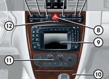
Controls in detail Instrument cluster
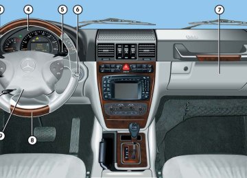
A full view illustration of the instrument cluster can be found in the “At a glance” section of this manual (컄 page 24).
1 Reset button The instrument cluster is activated when you: 앫 Open a door. 앫 Switch on ignition. 앫 Press reset button 1. 앫 Switch on the exterior lamps. You can change the instrument cluster set- tings in the Instrument cluster submenu of the control system (컄 page 135).
120
Instrument cluster illumination
Use the reset button to adjust the illumina- tion brightness for the instrument cluster.
The instrument cluster illumination is dimmed or brightened automatically to suit ambient light conditions. The instrument cluster illumination will also be adjusted automatically when you switch on the vehicle’s exterior lamps.
To brighten illumination 왘 Turn reset button 1 in the instrument
cluster clockwise. The instrument cluster illumination will brighten.
To dim illumination 왘 Turn reset button 1 in the instrument
cluster counterclockwise. The instrument cluster illumination will dim.
Coolant temperature display
Warning!
앫 Driving when your engine is badly over-
heated can cause some fluids which may have leaked into the engine com- partment to catch fire. You could be se- riously burned.
앫 Steam from an overheated engine can cause serious burns and can occur just by opening the hood. Stay away from the engine if you see or hear steam com- ing from it.
Turn off the engine, get out of the vehicle and do not stand near the vehicle until the engine has cooled down.
왘 Switch on the ignition (컄 page 35). 왘 Call up the trip odometer and main odometer (컄 page 123) by pressing button è or ÿ on the multifunc- tion steering wheel (컄 page 124).
왘 Press button j or k until the coolant temperature display appears. Excessive coolant temperature triggers a warning in the multifunction display (컄 page 306).
During severe operating conditions, e.g. stop-and-go traffic, the coolant tempera- ture may rise close to 248°F (120°C). The engine should not be operated with the coolant temperature above 248°F (120°C). Doing so may cause serious en- gine damage which is not covered by the Mercedes-Benz Limited Warranty.
Trip odometer
왘 Make sure you are viewing the trip
odometer display (컄 page 123).
왘 If it is not displayed, press button è or ÿ on the multifunction steering wheel (컄 page 124) until the trip odometer appears.
왘 Press and hold the reset button on the instrument cluster (컄 page 120) until the trip odometer is reset.
Controls in detail Instrument cluster
Tachometer
The red marking on the tachometer de- notes excessive engine speed.
Avoid driving at excessive engine speeds, as it may result in serious en- gine damage that is not covered by the Mercedes-Benz Limited Warranty.
To help protect the engine, the fuel supply is interrupted if the engine is operated within the red marking.
121
The temperature sensor is located in the front bumper area. Due to its location, the sensor can be affected by road or engine heat during idling or slow driving. This means that the accuracy of the displayed temperature can only be verified by com- parison to a thermometer placed next to the sensor, not by comparison to external displays (e.g. bank signs, etc.).
When moving the vehicle into colder ambi- ent temperatures (e.g. when leaving your garage), you will notice a delay before the lower temperature is displayed. A delay also occurs when ambient temper- atures rise. This prevents inaccurate tem- perature indications caused by heat radiated from the engine during idling or slow driving.
Controls in detail Instrument cluster
Outside temperature indicator
Warning!
The outside temperature indicator is not de- signed to serve as an ice-warning device and is therefore unsuitable for that purpose.
Indicated temperatures just above the freez- ing point do not guarantee that the road sur- face is free of ice. The road may still be icy, especially in wooded areas or on bridges.
The outside temperature is displayed in the multifunction display (컄 page 123). For information on how to select the unit of the displayed temperature, i.e. degrees Celsius (°C) or degrees Fahrenheit (°F), see “Selecting temperature display mode” (컄 page 135).
122
왔 Control system The control system is activated as soon as the SmartKey in the starter switch is turned to position 1. The control system enables you to 앫 call up information about your vehicle 앫 change vehicle settings For example, you can use the control sys- tem to find out when your vehicle is next due for service, to set the language for messages in the instrument cluster display and much more.
Controls in detail Control system
Warning!
Multifunction display
A driver’s attention to the road and traffic conditions must always be his/her primary focus when driving.
For your safety and the safety of others, se- lecting features through the multifunction steering wheel should only be done by the driver when traffic and road conditions per- mit it to be done safely.
Bear in mind that at a speed of just 30 mph (approximately 50 km/h), your vehicle is covering a distance of 44 feet (approximately 14 m) every second.
The control system relays information to the multifunction display.
1 Trip odometer 2 Main odometer 3 Outside temperature 4 Clock1
5 Current gear selector lever position 6 Transfer case program mode1 See separate operating
instructions
for the
COMAND system for clock setting.
123
Controls in detail Control system
Multifunction steering wheel
The displays in the multifunction display and the settings in the control system are controlled by the buttons on the multifunc- tion steering wheel.
124
G 55 AMG: The steering wheel in this vehicle may vary from steering wheel shown. However, multifunction steering wheel symbols and feature description apply to AMG vehicles as well.
1 Multifunction display
Operating the control system:
2 Selecting a submenu or setting the
volume: Press button æ up/to increase ç down/to decrease
3 Telephone*: Press button s to take a call, or
to dial a call
t to end a call, or
to reject an incoming call
4 Menu systems:
Press button è for next menu ÿ for previous menu
5 Moving within a menu:
Press button j for next display k for previous display
Pressing any of the buttons on the multi- function steering wheel will alter what is shown in the multifunction display. The information available in the multifunc- tion display is arranged in menus, each containing a number of functions or sub- menus. The individual functions are then found within the relevant menu (radio or CD op- erations under AUDIO, for example). These functions serve to call up relevant informa- tion or to customize the settings for your vehicle.
It is helpful to think of the menus, and the functions within each menu, as being ar- ranged in a circular pattern. 앫 If you press button è or ÿ
repeatedly, you will pass through each menu one after the other.
앫 If you press button k or j
repeatedly, you will pass through each function display, one after the other, in the current menu.
Controls in detail Control system
In the SETTINGS menu, instead of functions you will find a number of submenus for calling up and changing settings. For in- structions on using these submenus, see the “Settings menu” section (컄 page 132). The number of menus available in the sys- tem depends on which optional equipment is installed in your vehicle.
The headings used in the menus table are designed to facilitate navigation within the system and are not neces- sarily identical to those shown in the control system displays. The first function displayed in each menu will automatically show you which part of the system you are in.
125
Controls in detail Control system
Menus
This is what you will see when you scroll through the menus.
The table below provides an overview of the individual menus.
126
Menus, submenus and functions
Menu 2
AUDIOMenu 3
NAVI(컄 page 128) Select radio station
(컄 page 130) Activate route guidance
Select satellite radio station* (USA only)
Operate CD player
Menu 1
Standard display(컄 page 128) Coolant temperature display
Digital speedometer
Call up mainte- nance service indicator Check engine oil level
Menu 4
Vehicle status message memory (컄 page 131) Call up vehicle malfunction, warning and system status messages stored in memoryControls in detail Control system
Menu 5
SettingsMenu 6
Trip computerMenu 7
Telephone(컄 page 145) Load phone book
Search for name in phone book
(컄 page 144) Fuel consumption statistics after start Fuel consumption statistics since the last reset Call up range
(컄 page 132) Reset to factory settings
Instrument cluster submenu
Lighting submenu
Vehicle submenu
Convenience submenu
127
Controls in detail Control system
The headings used in the menus table are designed to facilitate navigation within the system and are not neces- sarily identical to those shown in the control system displays. The first function displayed in each menu will automatically show you which part of the system you are in.
128
Standard display menu
AUDIO menu
You can select the functions in the stan- dard display menu with button k or j. The following functions are available:
Function Call up coolant temperature display Call up digital speedometer Call up maintenance service indicator Check engine oil level
Page 120
128
278240
Display digital speedometer 왘 Press button j twice.
The current vehicle speed is shown in the multifunction display.
The functions in the AUDIO menu operate the audio equipment which you currently have turned on. If no audio equipment is currently turned on, the message AUDIO OFF is shown in the display. The following functions are available:
Function Select radio station Select satellite radio station* (USA only) Operate CD player
Page 129
129130
Select radio station 왘 Turn on the radio. Refer to separate op-
erating instructions.
왘 Press button è or ÿ repeatedly
until you see the currently tuned sta- tion in the display.
왘 Press button k or j repeatedly
until the desired station is found. The type of search depends on the set- ting for the station tuning: 앫 The next stored station is selected
(SP)
앫 Station search You can only store new stations by us- ing the corresponding feature on the radio. Refer to separate operating in- structions. You can also operate the radio in the usual manner.
1 Station 2 Waveband setting 3 Setting for station selection using
memory
Controls in detail Control system
Select satellite radio station* (USA only) The satellite radio is treated as a radio ap- plication. 왘 Select satellite radio with the corre-
sponding key on the COMAND control panel (SAT).
왘 Press button è or ÿ repeatedly
until you see the currently tuned sta- tion in the multifunction display.
1 Channel name or number 2 SAT mode and preset number 3 Setting for station selection using
memory
왘 Press button j or k repeatedly
until the desired channel is found.
129
Controls in detail Control system
Additional optional satellite radio equipment and a subscription to satel- lite radio service provider are required for satellite radio operation. Contact an authorized Mercedes-Benz Light Truck Center for details and availability for your vehicle. For more information, refer to separate COMAND operating instructions.
Satellite radio service may be unavail- able or interrupted from time to time for a variety of reasons, such as envi- ronmental or topographic conditions and other things beyond the service provider’s or our control. Service might also not be available in certain places (e.g. in tunnels, parking garages, or within or next to buildings) or near other technologies.
130
NAVI menu
The NAVI menu contains the functions needed to operate your navigation system. 왘 Press button è or ÿ repeatedly until you see the message NAVI in the display.
앫 If the navigation system is off, the mes- sage NAVI OFF is shown in the display. 앫 If the navigation system is on, the mes-
sage NAVI READY is shown in the dis- play.
Please refer to the COMAND manual for in- structions on how to activate the route guidance system*.
Operate the CD player 왘 Turn on the radio and select the CD
player. Refer to separate operating in- structions.
왘 Press button è or ÿ repeatedly until the settings for the CD currently being played are shown in the display.
1 Current track 2 Current CD (for CD changer) 왘 Press button k or j repeatedly
until the desired track is selected. To select a CD from the magazine, press a number on the COMAND sys- tem key pad located in the center dash- board.
Controls in detail Control system
Vehicle status message memory menu
왘 Press button è or ÿ repeatedly
왘 Press button k or j.
Use the vehicle status message memory menu to scan malfunction and warning messages that may be stored in the sys- tem. Such messages appear in the multi- function display and are based on conditions or system status the vehicle’s system has recorded.
Warning!
Malfunction and warning messages are only indicated for certain systems and are inten- tionally not very detailed. The malfunction and warning messages are simply a remind- er with respect to the operation of certain systems and do not replace the owner’s and/or driver’s responsibility to maintain the vehicle’s operating safety by having all required maintenance and safety checks performed on the vehicle and by bringing the vehicle to an authorized Mercedes-Benz Light Truck Center to address the malfunc- tion and warning messages (컄 page 296).
until you the vehicle status message memory appears in the multifunction display.
No vehicle status messages If no conditions are recorded in memory, the message in the multifunction display is: NO MALFUNCTION
Vehicle status messages have been recorded If conditions have occurred causing status messages to be recorded, the number of messages appears in the multifunction dis- play:
The stored messages will now be dis- played in order. See the “Practical hints” section for malfunction and warning messages (컄 page 296).
Should the vehicle’s system record any conditions while driving, the number of messages will reappear in the multifunc- tion display when the SmartKey in the starter switch is turned to position 0 or re- moved from the starter switch.
The vehicle status message memory will be cleared when you switch on igni- tion (컄 page 35). You will then only see high-priority messages in the multi- function display (컄 page 296).
1 Number of messages
131
Controls in detail Control system
Settings menu
In the SETTINGS... menu there are two functions: 앫 The function TO RESET: R BUTTON FOR 3 SEC., with which you can reset all the settings to those set at the factory.
앫 A collection of submenus with which you can make individual settings for your vehicle.
왘 Press button è or ÿ repeatedly
until the SETTINGS... menu is seen in the display.
Resetting all settings You can reset all the functions of all sub- menus to the factory settings. 왘 Press the reset button in the instru-
ment cluster (컄 page 120) for approxi- mately three seconds. In the display you will see the request to press the reset button again to con- firm.
왘 Press the reset button again.
The functions of all the submenus will reset to factory settings.
The settings you have changed will not be reset unless you confirm the action by pressing the reset button a second time. Approximately five seconds after pressing the reset button for the sec- ond time, the SETTINGS... menu reap- pears in the display. For safety reasons, the following func- tions are not reset while driving: 앫 the LIGHT CIRCUIT HEADLIGHT MODE function in the LIGHTING submenu 앫 the SETTINGS KEY- DEPENDENT func-
tion in the CONVENIENCE submenu
132
Resetting the functions of a submenu For each submenu you can reset all the functions to the factory settings. 왘 Move to a function in the submenu. 왘 Press the reset button in the instru-
ment cluster (컄 page 120) for approxi- mately three seconds. In the display you will see the request to press the reset button again to con- firm.
왘 Press the reset button again.
All functions of the submenu will reset to factory settings
Submenus in the Settings menu 왘 Press button k or j.
In the display you see the collection of the submenus.
왘 Press button ç.
The selection marker moves to the next submenu.
The submenus are arranged by hierarchy. Scroll down with the ç button, scroll up with the æ button. Move within the submenus with the k or j button to the individual functions. The settings themselves are made with button æ or ç.
Controls in detail Control system
The settings you have changed will not be reset unless you confirm the action by pressing the reset button a second time. Approximately five seconds after pressing the reset button for the sec- ond time, the SETTINGS... menu reap- pears in the display.
133
Controls in detail Control system
The table below shows what settings can be changed within the various menus. Detailed instructions on making individual settings can be found on the following pages.
INSTRUMENT CLUSTER (컄 page 135) Select time display mode
Select temperature display mode Select speedometer display mode Select language
Select display (speed display or outside temperature)
LIGHTING (컄 page 137) Set daytime running lamp mode (USA only) Set locator lighting
VEHICLE (컄 page 141) Set station selection mode (radio) Set automatic locking
CONVENIENCE (컄 page 142) Activate easy-entry/exit feature
Set key-dependency
Exterior lamps delayed switch-off Interior lighting delayed switch-off
Set parking position for exterior rear view mirror
134
Instrument cluster submenu Access the INSTRUMENT CLUSTER menu via the SETTINGS menu. Use the INSTRUMENT CLUSTER submenu to change the instru- ment cluster display settings. The follow- ing functions are available:
Function Select time display mode Select temperature display mode Select speedometer display mode Select language Select display (speed display or outside temperature)
Page 135
135136
136
137Controls in detail Control system
Selecting time display mode 왘 Move the selection marker with the æ or ç button to the INSTRUMENT CLUSTER submenu.
Selecting temperature display mode 왘 Move the selection marker with the æ or ç button to the INSTRUMENT CLUSTER submenu.
왘 Press button j or k repeatedly
왘 Press button j or k repeatedly
until you see this message in the display: 12/24 HOUR. The selection marker is on the current setting.
until you see this message in the dis- play: TEMP. INDICATOR. The selection marker is on the current setting.
왘 Press æ or ç to set the 12h or
24h time display mode.
왘 Press æ or ç to set temperature unit to degrees Celsius (°C) or degrees Fahrenheit (°F).
135
Controls in detail Control system
Selecting speedometer display mode 왘 Move the selection marker with the æ or ç button to the INSTRUMENT CLUSTER submenu.
Selecting language 왘 Move the selection marker with the æ or ç button to the INSTRUMENT CLUSTER submenu.
왘 Press button j or k repeatedly
왘 Press button j or k repeatedly
until you see this message in the dis- play: DISPLAY VALUES IN. The selection marker is on the current setting.
until you see this message in the dis- play: TEXT. The selection marker is on the current setting.
왘 Press æ or ç to select the lan-
guage to be used for the multifunction display messages. Available languages: 앫 German 앫 English 앫 French 앫 Italian 앫 Spanish
왘 Press æ or ç to set speedome-
ter unit to KM or Miles.
136
Controls in detail Control system
Selecting display (speed display or out- side temperature) 왘 Move the selection marker with the æ or ç button to the INSTRUMENT CLUSTER submenu.
왘 Press button j or k repeatedly
until you see this message in the dis- play: SELECT DISPLAY. The selection marker is on the current setting.
Lighting submenu Access the LIGHTING submenu via the SETTINGS menu. Use the LIGHTING sub- menu to change the lamp and lighting set- tings on your vehicle. The following functions are available:
Function Setting daytime running lamp mode (USA only) Setting locator lighting Setting night security illumination Setting interior lighting delayed shut-off
Page 137
138
139140
Setting daytime running lamp mode (USA only)
This function is not available in coun- tries where the daytime running lamp mode is mandatory and therefore in a constant mode.
왘 Move the selection marker with the æ or ç button to the LIGHTING submenu.
왘 Press button j or k repeatedly
until you see this message in the dis- play: LIGHT CIRCUIT HEADLIGHT MODE.
컄컄
왘 Press æ or ç to select the dis- play permanently shown in the multi- function display.