- 2012 Mercedes-Benz G Class Owners Manuals
- Mercedes-Benz G Class Owners Manuals
- 2005 Mercedes-Benz G Class Owners Manuals
- Mercedes-Benz G Class Owners Manuals
- 2013 Mercedes-Benz G Class Owners Manuals
- Mercedes-Benz G Class Owners Manuals
- 2009 Mercedes-Benz G Class Owners Manuals
- Mercedes-Benz G Class Owners Manuals
- 2003 Mercedes-Benz G Class Owners Manuals
- Mercedes-Benz G Class Owners Manuals
- 2004 Mercedes-Benz G Class Owners Manuals
- Mercedes-Benz G Class Owners Manuals
- 2011 Mercedes-Benz G Class Owners Manuals
- Mercedes-Benz G Class Owners Manuals
- 2002 Mercedes-Benz G Class Owners Manuals
- Mercedes-Benz G Class Owners Manuals
- 2007 Mercedes-Benz G Class Owners Manuals
- Mercedes-Benz G Class Owners Manuals
- Download PDF Manual
-
On slippery road surfaces, never downshift in order to obtain braking action. This could result in drive wheel slip and reduced vehi- cle control. Your vehicle’s ABS will not pre- vent this type of control loss.
컄컄
221
Operation Driving instructions
컄컄
Do not engage the transfer case in position LOW when driving on ice or packed snow. At speeds below 18 mph (30 km/h) vehicle steering is adversely affected by the LOW RANGE – ABS (컄 page 81).
Road salts and chemicals can adversely af- fect braking efficiency. Increased pedal force may become necessary to produce the normal brake effect. Depressing the brake pedal periodically when traveling at length on salt-strewn roads can bring road-salt-impaired braking efficiency back to normal. If the vehicle is parked after being driven on salt-treated roads, the braking efficien- cy should be tested as soon as possible af- ter driving is resumed.
Warning!
Make sure not to endanger any other road users when carrying out these braking ma- neuvers.
222
Warning!
Standing water
If the vehicle becomes stuck in snow, make sure snow is kept clear of the exhaust pipe and from around the vehicle with the engine running. Otherwise, deadly carbon monox- ide (CO) gases may enter vehicle interior re- sulting in unconsciousness and death.
To assure sufficient fresh air ventilation, open a window slightly on the side of the ve- hicle not facing the wind.
Warning!
The outside temperature indicator is not de- signed to serve as an ice-warning device and is therefore unsuitable for that purpose. In- dicated temperatures just above the freez- ing point do not guarantee that the road surface is free of ice.
Do not drive through flooded areas or water of unknown depth. Before driving through water, determine its depth. Never accelerate before driving into water. The bow wave could force water into the engine and auxiliary equip- ment, thus damaging them. If you must drive through standing wa- ter, drive slowly to prevent water from entering the passenger compartment or the engine compartment. Water in these areas could cause damage to electrical components or wiring of the engine or transmission, or could result in water being ingested by the engine through the air intake, causing severe internal engine damage. Any such dam- age is not covered by the Mercedes-Benz Limited Warranty.
For more information, see “Winter driving” (컄 page 275).
For more information, see “Driving through water” (컄 page 227).
Operation Driving instructions
Do not load items on the roof. It may cause instability during some maneuvers which could result in an accident. This vehicle is not intended to carry items on its roof. Thus roof rails and roof mounted ski or bike hold- ers must not be used.
Off-road driving
Warning!
Do not load items on the roof. It may cause instability during some maneuvers which could result in an accident.
Warning!
Drive slowly in unknown terrain. This will make it easier to recognize unexpected ob- stacles and avoid damage to the vehicle.
To help avoid the vehicle rolling over, never turn it around on steep inclines. If the vehi- cle cannot complete the attempted climb, back it down in reverse gear.
Do not drive along the side of a slope (dan- ger of vehicle rollover). If in doing so the ve- hicle begins to show a tendency to roll, immediately steer into a line of gravity (straight up or downhill).
컄컄
Passenger compartment
Warning!
Always fasten items being carried as secure- ly as possible.
In an accident, during hard braking or sud- den maneuvers, loose items will be thrown around inside the vehicle, and cause injury to vehicle occupants unless the items are securely fastened in the vehicle.
The rear cargo compartment is the preferred place to carry objects. Always use partition net when transporting cargo. Partition net cannot secure hard or heavy objects. Al- ways fasten items being carried as securely as possible using the cargo tie-down rings in the cargo compartment floor and fastening material.
223
Operation Driving instructions
컄컄
Never let the vehicle roll backwards in idle. You may lose control of the vehicle if you use only the brake.
Sand, dirt, mud and other material having friction property can cause exceptional wear and tear as well as brake failure.
Have the brakes checked for dirt build-up and cleaned. There is otherwise a risk that full braking power may not be available in an emergency.
Read this chapter carefully before you be- gin off-road travel. Familiarize yourself with the vehicle char- acteristics and gear changing before you attempt any difficult terrain off-road driv- ing. We recommend that you start out with easy off-road travel.
224
Special driving features for off-road driving The following driving features are available for specific kind of operation: 앫 ABS (컄 page 80) 앫 ESP (컄 page 84) 앫 4-ETS (컄 page 83) 앫 Differential lock (컄 page 156) 앫 Transfer case (컄 page 154)
Off-road driving rules 왘 Engage the transfer case in position
LOW before driving under off-road con- ditions (컄 page 154).
왘 If necessary activate differential locks
(컄 page 158). The ABS, BAS and ESP are switched off automatically when the differential locks are activated.
왘 Fasten items being carried as securely
as possible (컄 page 187).
Whenever driving in off-road mode, we recommend: 앫 Keeping doors, tailgate, windows
and tilt/sliding sunroof closed.
앫 Switching cruise control off.
Observe the following during off-road driving: 앫 Adjust vehicle speed to condition of terrain. The more uneven, rutty and steeper the terrain, the lower the speed should be. Drive through wa- ter slowly at an even speed, avoid- ing a bow wave.
앫 Be especially careful when driving in unknown territory. It may be nec- essary to get out of the vehicle and scout the path you intend to take. 앫 Watch out for obstacles, such as
rocks, holes, tree stumps and ruts.
앫 Avoid excessive engine
speeds – drive at moderate engine speeds (max. 3000 rpm).
앫 Before driving through water, deter-
mine its depth.
앫 Do not stop vehicle while immersed in water, and do not shut off the en- gine.
앫 In sandy soil, drive at a steady
speed as allowed by conditions. This helps overcome the vehicle rolling resistance and reduces the likelihood of the vehicle sinking into the ground.
앫 Do not initiate jumps with the vehi-
cle. It interrupts the forward mo- mentum of the vehicle.
앫 Always drive on slopes with the en-
gine running and the vehicle in gear.
앫 Inspect the vehicle for possible damage after each off-road trip.
Checklist before off-road driving
Engine oil level 앫 Check the engine oil level
(컄 page 240). The display ENGINE OIL LEVEL - OK must appear in the multi- function display. Only then can the vehicle obtain a trou- ble-free oil supply, even on steep gradi- ents.
Tires 앫 Check the tread depth and maintain
specified tire inflation pressure (a placard with the recommended tire inflation pressures is located on the driver’s door B-pillar (컄 page 251)).
앫 Check tires for possible damage and
remove foreign objects.
앫 Replace missing valve caps.
Operation Driving instructions
Rims 앫 Dented or bent rims can cause tire in- flation pressure loss and damage the tire beads. For this reason, check and, if necessary, change rims before driv- ing off-road.
Vehicle tool kit 앫 Check if the vehicle jack is functional. 앫 In all cases take the vehicle tool kit, a strong tow rope, a shovel and a small plank (to put under the vehicle jack on sandy soil) with you.
225
Operation Driving instructions
Driving in steep terrain
Slope angle 1 27° 2 36° 앫 Comply with the warnings
(컄 page 223) and rules for off-road driving (컄 page 224).
앫 Driving on embankments, slopes and
other steep inclines should only be done straight up or downhill, i.e. in the line of gravity. Maximum vehicle climb- ing ability is a 80% grade.
앫 Select gear range 2 or 1 on the auto-
matic transmission (컄 page 150).
226
Driving across a hilltop Decelerate just ahead of a hilltop (do not select gear range N), to prevent the vehi- cle from speeding up too much after climb- ing a hill. Use the momentum of the vehicle to drive across the hilltop. After climbing a hill, driving in this manner prevents the vehicle from: 앫 jumping across the hilltop 앫 loosing its forward momentum 앫 speeding up too much after climbing
the hill
앫 Drive slowly. 앫 Utilize the engine’s braking power
when descending a slope, observe the engine speed (do not overrev the en- gine). Apply the brake as needed.
앫 Check the brakes after a lengthy down-
grade drive.
Traction in steep terrain Be easy on the accelerator and watch for continuous wheel traction when driving in steep terrain.
The 4-ETS helps greatly when starting out on a steep incline when the front wheels have then the tendency to slip due to the weight shifting away the front axle.The 4-ETS recognizes the sit- uation and limits the torque for the front wheels by braking them. Simulta- neously the torque for the rear wheels is provided.
Driving downhill 앫 Select gear range 1 on the automatic
transmission (컄 page 150).
앫 Drive downhill observing the same rules as driving uphill (컄 page 226).
Only apply the service brake if the vehi- cle is traveling straight downhill, i.e. in the line of gravity.
The special LOW RANGE – ABS setting allows for precise and brief (cyclical) blocking of the front wheels, permitting them to dig into loose ground. Remember that, when stopped, the front wheels slide across a surface and thus lose their ability to steer the vehi- cle.
Driving through water
1 19 in (48 cm) 앫 Before driving through water, deter-
mine its depth. It should not be deeper than approxi- mately 19 in (48 cm). Make sure you check the water bed. The ground surface may not be firm which may result in deeper waters than expected when driving the vehicle through it.
Operation Driving instructions
앫 Comply with the warnings
(컄 page 223) and rules for off-road driving (컄 page 224).
앫 Switch off the exterior lamps as well as
the climate control.
앫 Select gear range 2 or 1 on the auto-
matic transmission (컄 page 150).
앫 Enter the water only at a shallow spot,
driving at walking speed.
Never accelerate before driving into the water. The bow wave could force water into the engine and auxiliary equipment, thus damaging them.
227
Crossing obstacles
Operation Driving instructions
앫 Do not stop vehicle while immersed in water, and do not shut off the engine. There is a very high level of driving re- sistance in water. The surface is slip- pery and may not be firm, making pulling away in water difficult and dan- gerous.
앫 Clean mud off the tire tread after driv-
ing through water.
앫 To dry the brakes, apply pressure to the brake pedal several times after leaving the water.
228
If possible, use the assistance of a sec- ond person outside the vehicle to scout the path you intend to take and check for adequate ground clearance when you cross obstacles with your vehicle. The person assisting you outside the vehicle should always be a safe dis- tance away from the vehicle and posi- tioned so that he or she cannot get hurt in case of any unexpected vehicle movement. After off-road driving or crossing obsta- cles, inspect vehicle for any damage, especially vehicle underbody and sus- pension components. Failure to do so can adversely affect the vehicle’s fu- ture performance, including increased chance of an accident.
앫 Check the vehicle clearance before
Ruts
crossing obstacles.
앫 Comply with the warnings
(컄 page 223) and rules for off-road driving (컄 page 224).
앫 Select gear range 1 on the automatic
transmission (컄 page 150).
앫 Cross obstacles (e.g. tree stumps or
big rocks) very slowly by aiming one of the front wheels at the center of the ob- stacle, and repeat same with the rear wheel.
Special attention is needed when you cross obstacles on a steep incline. The vehicle could slide sideways as a result of its possible slanted position which in turn may result in the vehicle tipping or rolling over.
A number of off-road tracks or other by- roads have deep ruts. If the vehicle does not have enough ground clear- ance: 앫 it could be damaged 앫 the underside of the vehicle may come down on a surface and re- main stuck
After off-road driving or crossing obsta- cles, inspect vehicle for any damage, especially vehicle underbody and sus- pension components. Failure to do so can adversely affect the vehicle’s fu- ture performance, including increased chance of an accident.
Operation Driving instructions
앫 Check the vehicle clearance before
driving in ruts.
앫 Comply with the warnings
(컄 page 223) and rules for off-road driving (컄 page 224).
앫 Select gear range 1 on the automatic
transmission (컄 page 150).
앫 Drive slowly next to the ruts rather than
through them if at all possible.
229
Off-road driving increases strain on the ve- hicle. We recommend that you inspect the vehi- cle for possible damage after each off-road trip. Recognizing any damage and a subse- quent timely repair reduces the chance of a possible breakdown or accident later on. Proceed as follows: 앫 Switch the transfer case in position
HIGH (컄 page 154).
앫 Disengage differential locks
(컄 page 159).
앫 Remove excessive dirt from tires,
wheels, wheel housings, and under- body. For instance, after driving in mud, clean the radiator, chassis, engine, brakes, and wheels from extreme dirt using a strong jet of water.
앫 Inspect frame, oil pan, brake hoses, etc., as well as vehicle underbody for possible damage.
앫 Check tires for possible damage and remove foreign objects. Clean all exte- rior lamps and conduct a brake test.
Operation Driving instructions
Returning from off-road driving
Warning!
Never drive on pavement with activated dif- ferential locks. Engaged front axle differen- tial locks limits ability to move around curves.
If you feel a sudden significant vibration or ride disturbance, or you suspect that possi- ble damage to your vehicle has occurred, you should turn on the hazard warning flash- ers, carefully slow down, and drive with cau- tion to an area which is a safe distance from the roadway.
Inspect the tires and under the vehicle for possible damage. If the vehicle or tires ap- pear unsafe, have it towed to the nearest Mercedes-Benz Light Truck Center or tire dealer for repairs.
Damage to the vehicle negatively influences driving comfort and poses the risk of acci- dent to you and other drivers.
230
앫 Clean all exterior lamps and check
them for possible damage.
Control and operation of radio trans- mitters
Telephones and two-way radios
Operation Driving instructions
앫 Check for brush or branches caught in
the underbody. They could increase the possibility of a fire, as well as cut fuel and/or brake lines, puncture rubber bellows of the axles or drive shafts.
앫 After continued operation in mud,
sand, water or other dirty conditions, clean the brake discs, wheels, brake pads and check and clean axle joints.
앫 Conduct a brake test.
COMAND, radio and telephone*
Warning!
Do not forget that your primary responsibili- ty is to drive the vehicle safely. Only operate the COMAND, radio or telephone1 if road, traffic and weather conditions permit.
Bear in mind that at a speed of just 30 mph (approximately 50 km/h), your vehicle is covering a distance of 44 feet (approximately 14 m) every second.
1 Observe all legal requirements.
Warning!
Never operate radio transmitters equipped with a built-in or attached antenna (i.e. with- out being connected to an external antenna) from inside the vehicle while the engine is running. Doing so could lead to a malfunc- tion of the vehicle’s electronic system, pos- sibly resulting in an accident and/or personal injury.
Radio transmitters, such as a portable tele- phone or citizens band unit should only be used inside the vehicle if they are connect- ed to an antenna that is installed on the outside of the vehicle. Refer to the radio transmitter operation in- structions regarding use of an external an- tenna.
231
Operation Driving instructions
Driving abroad
Catalytic converter
Abroad, there is an extensive Mercedes-Benz service network at your disposal. If you plan to drive into areas which are not listed in the index of an Mercedes-Benz Light Truck Center directo- ry, you should request pertinent informa- tion from an authorized Mercedes-Benz Light Truck Center.
Your Mercedes-Benz is equipped with monolithic-type catalytic converters, an important element in conjunction with the oxygen sensors to achieve substantial con- trol of the pollutants in the exhaust emis- sions. Keep your vehicle in proper operating condition by following our rec- ommended maintenance instructions as outlined in your Maintenance Booklet.
To prevent damage to the catalytic con- verters, use only premium unleaded gasoline in this vehicle. Any noticeable irregularities in engine operation should be repaired promptly. Otherwise, excessive unburned fuel may reach the catalytic converter, causing it to overheat and potentially start a fire.
232
Warning!
Emission control
As with any vehicle, do not idle, park or op- erate this vehicle in areas where combusti- ble materials such as grass, hay or leaves can come into contact with the hot exhaust system, as these materials could be ignited and cause a vehicle fire.
Certain engine systems serve to keep the toxic components of the exhaust gases within permissible legal limits. These systems, of course, will function properly only when maintained strictly ac- cording to factory specifications. Any ad- justments on the engine should, therefore, be carried out only by qualified Mercedes-Benz Light Truck Center autho- rized technicians. Engine adjustments should not be altered in any way. More- over, the specified service jobs must be carried out regularly according to Mercedes-Benz servicing requirements. For details refer to the Maintenance Booklet.
Operation Driving instructions
Warning!
Inhalation of exhaust gas is hazardous to your health. All exhaust gas contains carbon monoxide, and inhaling it can cause uncon- sciousness and lead to death.
Do not run the engine in confined areas (such as a garage) which are not properly ventilated. If you think that exhaust gas fumes are entering the vehicle while driving, have the cause determined and corrected immediately. If you must drive under these conditions, drive only with at least one win- dow fully open at all times.
233
Operation Driving instructions
Coolant temperature
During severe operating conditions, e.g. stop-and-go city traffic, the coolant tem- perature may rise to approx. 248°F (120°C). The engine should not be operated with the coolant temperature above 248°F (120°C). Doing so may cause serious en- gine damage which is not covered by the Mercedes-Benz Limited Warranty.
Excessive coolant temperatures trigger a warning message in the multifunction display (컄 page 306).
Warning!
앫 Driving when your engine is badly over-
heated can cause some fluids which may have leaked into the engine com- partment to catch fire. You could be se- riously burned.
앫 Steam from an overheated engine can cause serious burns and can occur just by opening the hood. Stay away from the engine if you see or hear steam com- ing from it.
Turn off the engine, get out of the vehicle and do not stand near the vehicle until the engine has cooled down.
234
왔 At the gas station Refueling
Warning!
Gasoline is highly flammable and poisonous. It burns violently and can cause serious inju- ry. Whenever you are around gasoline, avoid inhaling fumes and skin contact, extinguish all smoking materials. Never allow sparks, flame or smoking materials near gasoline!
Failure to remove the fuel cap slowly could result in personal injury.
The fuel filler flap is located on the right-hand side of the vehicle towards the rear. Locking/unlocking the vehicle with the re- mote control automatically locks/unlocks the fuel filler flap.
1 Fuel filler flap (including a placard on the inner side with supplemental tire inflation pressure information)
2 Fuel cap 왘 Turn off the engine. 왘 Remove the SmartKey from the starter
switch.
왘 Open fuel filler flap 1 by pushing at
the point indicated by the arrow.
왘 Turn fuel cap 2 to the left and hold on to it until possible pressure is released. 왘 Take off fuel cap 2 and set it in the re-
cess on fuel filler flap 1.
Operation At the gas station
왘 To prevent fuel vapors from escaping into open air, fully insert filler nozzle unit.
왘 Only fill your tank until the filler nozzle unit cuts out – do not top up or over- fill.
Warning!
Overfilling of the fuel tank may create pres- sure in the system which could cause a gas discharge. This could cause the gas to spray back out when removing the fuel pump noz- zle, which could cause personal injury.
왘 Replace fuel cap 2 by turning it to the
right. You should hear the fuel filler cap en- gage.
왘 Close fuel filler flap 1.
컄컄
235
Check regularly and before a long trip
Leaving the engine running and the fuel cap open can cause the ? malfunc- tion indicator lamp (USA only) or the ± malfunction indicator lamp (Canada only) to illuminate. See also “Practical hints” section (컄 page 292).
G 500
1 Coolant 2 Brake fluidOperation At the gas station
컄컄
The fuel filler cap is tethered to the fuel filler neck. Do not drop the cap. It could damage the vehicle paint finish. When refueling the vehicle, make cer- tain that no gasoline comes into con- tact with plastic tail lamp to prevent damaging the lens.
Use only premium unleaded gasoline with a minimum Posted Octane Rating of 91 (average of 96 RON/86 MON). Information on gasoline quality can normally be found on the fuel pump. More information on gasoline can be found in the Factory Approved Service Products pamphlet.
236
G 55 AMG 1 Coolant 2 Brake fluid
Opening the hood, see (컄 page 238).
Coolant For normal replenishing, use water (pota- ble water quality). For more information, see “Coolant level” (컄 page 244) and see “Fuels, coolants, lubricants, etc.” (컄 page 374).
Brake fluid
If you find that the brake fluid in the brake fluid reservoir has fallen to the minimum mark or below, have the brake system checked for brake pad thickness and leaks immediately. Noti- fy an authorized Mercedes-Benz Light Truck Center immediately. Do not add brake fluid as this will not solve the problem. For more information, see “Practical hints” (컄 page 290).
Operation At the gas station
Engine oil level For more information on engine oil, see “Engine oil” (컄 page 239).
Tire inflation pressure For more information, see “Checking tire inflation pressure” (컄 page 259).
Vehicle lighting Check function and cleanliness. For infor- mation on replacing light bulbs, see “Re- placing bulbs” (컄 page 333). For more information, see “Exterior lamp switch” (컄 page 110).
Windshield/rear window washer sys- tem and headlamp cleaning system For more information on refilling the reser- voir, see “Windshield/rear window washer system and headlamp cleaning system” (컄 page 245).
237
Operation Engine compartment
Hood
Warning!
Do not pull the release lever while the vehi- cle is in motion. Otherwise the hood could be forced open by passing air flow.
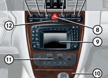
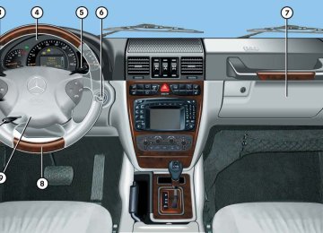
Opening The pull release lever is under the driver’s side of the instrument panel.
왘 Pull release lever 1 upward.
The hood is unlocked.
To avoid damage to the windshield wip- ers or hood, open the hood only with wipers in parked position.
2 Safety hook 왘 Lift hood up slightly. 왘 Pull safety hook 2 in direction of ar-
row and open hood.
1 Release lever
238
Warning!
To help prevent personal injury, stay clear of moving parts when the hood is open and the engine is running. Make sure the hood is properly closed before driving. When closing the hood, use extreme caution not to catch hands or fingers. The radiator fan may continue to run for ap- proximately 30 seconds or even restart af- ter the engine has been turned off. Stay clear of fan blades.
Warning!
If you see flames or smoke coming from the engine compartment, or if the coolant tem- perature display indicates that the engine is overheated, do not open the hood. Move away from vehicle and do not open the hood until the engine has cooled down. If neces- sary, call the fire department.
Warning!
Closing
The engine is equipped with a transistorized ignition system. Because of the high voltage, it is dangerous to touch any components (ig- nition coils, spark plug sockets, diagnostic socket) of the ignition system 앫 with the engine running 앫 while starting the engine 앫 if ignition is “on” and the engine is
turned manually
Warning!
Be careful that you do not close the hood on anyone.
왘 Lower hood and let it drop into lock from a height of approximately 0.7 ft (20 cm). The hood will lock audibly.
왘 Check to make sure the hood is fully
closed. If you can raise the hood at a point above the turn signals to the left and right of the hood, then it is not properly closed. Open it again and let it drop with somewhat greater force.
Do not push the hood closed manually, as this could damage it.
Operation Engine compartment
Engine oil
The amount of oil your engine needs will depend on a number of factors, including driving style. Higher oil consumption can occur when 앫 the vehicle is new 앫 the vehicle is driven frequently at
higher engine speeds
Engine oil consumption checks should only be made after the vehicle break-in period.
Do not use any special lubricant addi- tives, as these may damage the drive assemblies. Using special additives not approved by Mercedes-Benz may cause damage not covered by the Mercedes-Benz Limited Warranty. More information on this subject is available at any Mercedes-Benz Light Truck Center.
239
Operation Engine compartment
Checking engine oil level with the control system When checking the oil level 앫 the vehicle must be parked on level
ground
앫 with the engine at operating tempera- ture, the vehicle must have been sta- tionary for at least five minutes with the engine turned off
앫 with the engine not at operating tem- perature yet, the vehicle must have been stationary for at least 30 minutes with the engine turned off
To check the engine oil level via the multifunction display, do the following: 왘 Switch on the ignition (컄 page 35). The standard display (컄 page 123) should appear in the multifunction display.
240
왘 Press button k or j on the steering wheel until the following message is seen in the multifunction display:
ENGINE OIL LEVEL MEASURING NOW
MEASURE. CORRECT ONLY IF VEH. LEVEL
One of the following messages will subsequently appear in the indicator: 앫 ENGINE OIL LEVEL
OK
앫 ADD 1.0 Qt. TO
REACH MAX. OIL LEVEL!
(Canada: 1.0 LITER)
앫 ADD 1.5 Qts. TO
REACH MAX. OIL LEVEL!
(Canada: 1.5 LITERS)
앫 ADD 2.0 Qts. TO
REACH MAX. OIL LEVEL!
(Canada: 2.0 LITERS)
If you want to interrupt the checking procedure, press the k or j button on the multifunction steering wheel.
왘 If necessary, add engine oil. For adding engine oil see (컄 page 243). For more information on engine oil, see the “Technical data” section (컄 page 374) and (컄 page 375).
Other display messages If the SmartKey is not turned to position 2 in the starter switch, the following message will appear: FOR ENGINE OIL LEVEL SWITCH ON IGNITION! 왘 Switch on the ignition (컄 page 35). If you see the message: OBSERVE WAITING PERIOD 왘 If engine is at operating temperature,
wait five minutes before repeating check procedure.
왘 If engine is not at operating tempera-
ture yet, wait 30 minutes before re- peating check procedure.
If you see the message:
ENGINE OIL LEVEL NOT WHEN ENGINE ON! 왘 Turn off the engine. 왘 If the engine is at operating tempera-
ture, wait five minutes before checking oil.
왘 If the engine is not at operating temper-
ature yet, you must wait 30 minutes before checking oil.
If there is excess engine oil with the engine at normal operating temperature, the following message will appear: ENGINE OIL LEVEL REDUCE OIL LEVEL 왘 Have excess oil siphoned or drained
off. Contact an authorized Mercedes-Benz Light Truck Center.
Operation Engine compartment
Excess oil must be siphoned or drained off. It could cause damage to the engine and catalytic converter not covered by the Mercedes-Benz Limited Warranty.
Perform the engine oil level check with the dipstick if it cannot be completed with the control system (컄 page 242). In this case we recommend that you have the system checked at a Mercedes-Benz Light Truck Center.
For more information on messages in the multifunction display concerning engine oil, see the “Practical hints” section (컄 page 296).
241
Operation Engine compartment
Checking engine oil level with the oil dipstick When checking the oil level the vehicle must 앫 be parked on level ground 앫 be at normal operating temperature 앫 have been stationary for at least five
minutes with the engine turned off The engine oil level can be checked by either the oil dipstick or via the multi- function display in the instrument cluster (컄 page 240). The amount of engine oil needed is shown more precisely in the multifunction display.
To check the engine oil level with the oil dipstick, do the following: 왘 Open the hood (컄 page 238). 왘 Pull out oil dipstick 1 (컄 page 243). 왘 Wipe oil dipstick 1 clean. 왘 Fully insert oil dipstick 1 into the
dipstick guide tube.
왘 Pull out oil dipstick 1 again after
approximately three seconds to obtain accurate reading.
The filling quantity between the upper and lower marks on the oil dipstick is approximately 2.1 US qt. (2.0 l).
왘 If necessary, add engine oil. For adding engine oil see (컄 page 243). For more information on engine oil, see the “Technical data” section (컄 page 374) and (컄 page 375). For more information on messages in the multifunction display concerning engine oil, see the “Practical hints” section (컄 page 309).
Oil dipstick The oil level is correct when it is between the lower (min) and upper (max) mark of the oil dipstick.
242
Adding engine oil Only use approved engine oils and oil fil- ters required for vehicles with Maintenance System (U.S. vehicles) or FSS (Canada vehicles). For a listing of ap- proved engine oils and oil filters, refer to the Factory Approved Service Products pamphlet in your vehicle literature portfo- lio, or contact an authorized Mercedes-Benz Light Truck Center. Using engine oils and oil filters of specifica- tion other than those expressly required for the Maintenance System (U.S. vehi- cles) or FSS (Canada vehicles), or changing of oil and oil filter at change intervals long- er than those called for by the Maintenance System (U.S. vehicles) or FSS (Canada vehicles) will result in engine damage not covered by the Mercedes-Benz Limited Warranty.
G 500
1 Oil dipstick 2 Oil filler capOperation Engine compartment
G 55 AMG 1 Oil dipstick 2 Oil filler cap 왘 Unscrew oil filler cap 2 from filler
neck.
왘 Add engine oil as required. Be careful
not to overfill with oil.
Be careful not to spill any oil when adding. Avoid environmental damage caused by oil entering the ground or water.
컄컄
243
Operation Engine compartment
컄컄
Excess oil must be siphoned or drained off. It could cause damage to the engine and catalytic converter not covered by the Mercedes-Benz Limited Warranty.
왘 Screw oil filler cap 2 back on filler
neck.
For more information on engine oil, see the “Technical data” section (컄 page 374) and (컄 page 375).
244
Transmission fluid level
The transmission fluid level does not need to be checked. The transmission has a per- manent supply of automatic transmission fluid. If you notice transmission fluid loss or gear shifting malfunctions, have an authorized Mercedes-Benz Light Truck Center check the automatic transmission.
Coolant level
The engine coolant is a mixture of water and anticorrosion/antifreeze. When checking the coolant level, 앫 the vehicle must be parked on level
ground.
앫 the engine must be cool. The coolant level should reach the COLD LEVEL mark in the reservoir.
Warning!
In order to avoid any possibly serious burns: 앫 Use extreme caution when opening the hood if there are any signs of steam or coolant leaking from the cooling system, or if the coolant temperature display in- dicates that the coolant is overheated. 앫 Do not remove pressure cap on coolant
reservoir if coolant temperature is above 158°F (70°C). Allow engine to cool down before removing cap. The coolant reservoir contains hot fluid and is under pressure.
앫 Using a rag, slowly open the cap approx- imately 1/2 turn to relieve excess pres- sure. If opened immediately, scalding hot fluid and steam will be blown out un- der pressure.
앫 Do not spill antifreeze on hot engine
parts. Antifreeze contains ethylene gly- col which may burn if it comes into con- tact with hot engine parts.
The coolant expansion tank is located on the passenger side of the engine compart- ment.
왘 Using a rag, turn the cap slowly approx-
imately one half turn to the left to re- lease any excess pressure.
1 Cap
왘 Continue turning the cap to the left and
remove it.
왘 Check coolant level.
The coolant level is correct if the level 앫 for cold coolant: is level with the
mark on the reservoir
앫 for warm coolant: is approx. 0.6 in
(1.5 cm) higher
왘 Add coolant as required. 왘 Replace and tighten cap until you hear
it click a few times.
For more information on coolant, see “Coolants” (컄 page 378).
Operation Engine compartment
Windshield/rear window washer sys- tem and headlamp cleaning system
The windshield washer reservoir is located in the engine compartment on the passen- ger side. It holds approximately 5.3 US qt (5.0 l). The headlamp cleaning system is also supplied from the windshield washer reservoir.
1 Cap
245
Operation Engine compartment
왘 Use the tab to pull cap 1 upwards. 왘 Check washer solvent level and add
washer solvent as required.
왘 Press cap 1 on the filler neck until is
has completely engaged.
Add MB Windshield Washer Concentrate “S” to the water during all seasons. 앫 At temperatures above freezing point,
use MB Windshield Washer Concentrate “S” to prevent smearing.
앫 If there is a danger of frost, use
MB Windshield Washer Concentrate “S” and commercially available pre- mixed windshield washer solvent/anti- freeze to prevent water from freezing on the windshield and the reservoir from being damaged.
Premix the windshield washer fluid in a suitable container, adapting the mixing ratio to the outside temperature (컄 page 380).
Warning!
Washer solvent/antifreeze is highly flam- mable. Do not spill washer solvent/antifreeze on hot engine parts, be- cause it may ignite and burn. You could be seriously burned.
Only use washer fluid which is suitable for plastic lenses. Improper washer flu- id can damage the plastic lenses of the headlamps.
246
왔 Battery The battery is located in front of the rear seat bench and below the cup holder. Jump starting terminals are located in the left side of the engine compartment (컄 page 355). Refer to Maintenance Booklet for battery maintenance intervals. The battery should always be sufficiently charged in order to achieve its rated ser- vice life. If you use your vehicle less than approxi- mately 200 miles (300 km) per month, mostly for short-distance trips, or if it is not used for long periods of time, you will need to have the battery charge checked more frequently and corrected if necessary. When replacing batteries, always use bat- teries approved by Mercedes-Benz. If you do not intend to operate your vehicle for an extended period of time, consult an authorized Mercedes-Benz Light Truck Center about steps you need to observe.
G Observe all safety instructions
and precautions when handling automotive batteries.
A Risk of explosion D Keep flames or sparks away
from battery. Do not smoke.
B Battery acid is caustic. Do not
allow it to come into contact with skin, eyes or clothing. In case it does, immediately flush affected area with clear water and seek medical help if necessary.
E Wear eye protection. C Keep children away. F Follow the instructions in this
Operator’s Manual.
Operation Battery
Batteries contain materials that can harm the environment if disposed of improperly. Recycling of batteries is the preferred method of disposal. Many states require sellers of batteries to accept old batteries for recycling.
If the battery is discharged 앫 you will no longer be able to turn the SmartKey in the starter switch 앫 the gear selector lever will remain
locked in position P
For more information, see “Battery” (컄 page 351).
247
Operation Tires and wheels
See an authorized Mercedes-Benz Light Truck Center for information on tested and recommended rims and tires for summer and winter operation. They can also offer advice concerning tire service and purchase.
Warning!
Replace rims or tires with the same designa- tion, manufacturer and type as shown on the original part. See an authorized Mercedes-Benz Light Truck Center for fur- ther information. If incorrectly sized rims and tires are mounted: 앫 The wheel brakes or suspension
components can be damaged.
앫 The operating clearance of the wheels and the tires may no longer be correct.
248
Warning!
Important guidelines
Worn, old tires can cause accidents. If the tire tread is badly worn, or if the tires have sustained damage, replace them.
When replacing rims, only use genuine Mercedes-Benz wheel bolts specified for the particular rim type. Failure to do so can result in the bolts loosening and possibly an accident.
Retreaded tires are not tested or recom- mended by Mercedes-Benz, since previous damage cannot always be recognized on retreads. The operating safety of the vehicle cannot be assured when such tires are used.
앫 Only use sets of tires and rims of the
same type and make.
앫 Tires must be of the correct size for the
rim.
앫 Break in new tires for approximately
60 miles (100 km) at moderate speeds.
앫 Regularly check the tires and rims for
damage. Dented or bent rims can cause tire inflation pressure loss and damage to the tire beads.
앫 If vehicle is heavily loaded, check tire
inflation pressure and correct as required.
앫 Do not allow your tires to wear down too far. Adhesion properties on wet roads are sharply reduced at tread depths under 1/8 in (3 mm).
앫 When replacing individual tires, you should mount new tires on the front wheels first (on vehicles with same-sized wheels all around).
Operation Tires and wheels
Tire care and maintenance
Warning!
Regularly check the tires for damage. Dam- aged tires can cause tire inflation pressure loss. As a result, you could lose control of your vehicle.
Worn, old tires can cause accidents. If the tire tread is badly worn, or if the tires have sustained damage, replace them.
Regularly check your tire inflation pressure at least once a month. For more informa- tion on checking tire inflation pressure see “Recommended tire inflation pressure” (컄 page 257).
Tire inspection Every time you check your tire inflation pressure, you should also inspect your tires for the following: 앫 excessive treadwear (컄 page 250) 앫 cord or fabric showing through the
tire’s rubber
Life of tire The service life of a tire is dependent upon varying factors including but not limited to: 앫 Driving style 앫 Tire inflation pressure 앫 Distance driven
앫 bumps, bulges, cuts, cracks or splits in
the tread or side of the tire
Warning!
Tires and spare tire should be replaced after six years, regardless of the remaining tread.
Replace the tire if you find any of the above conditions. Make sure you also inspect the spare tire periodically for condition and inflation. Spare tires will age and become worn over time even if never used, and thus should be inspected and replaced when necessary.
249
Operation Tires and wheels
Tread depth Do not allow your tires to wear down too far. Adhesion properties on wet roads are sharply reduced at tread depths under 1/8 in (3 mm). Treadwear indicators (TWI) are required by law. These indicators are located in six places on the tread circumference and become visible at a tread depth of approx- imately 1/16 in (1.6 mm), at which point the tire is considered worn and should be replaced. Recommended minimum tire tread depth: 앫 Summer tires 1/8 in (3 mm) 앫 Winter tires 1/6 in (4 mm)
Warning!
Although the applicable federal motor safety laws consider a tire to be worn when the treadwear indicators (TWI) become visible at approximately 1/16 in (1.6 mm), we recom- mend that you do not allow your tires
250
to wear down to that level. As tread depth approaches 1/8 in (3 mm), the adhesion properties on a wet road are sharply re- duced.
Depending upon the weather and/or road surface (conditions), the tire traction varies widely.
Storing tires
Keep unmounted tires in a cool, dry place with as little exposure to light as possible. Protect tires from contact with oil, grease and gasoline.
Cleaning tires
Never use a round nozzle to power wash tires. The intense jet of water can result in damage to the tire. Always replace a damaged tire.
1 TWI (Tread Wear Indicator) The treadwear indicator appears as a solid band across the tread.
Operation Tires and wheels
can be carried in the vehicle. It also contains information on the proper size and recommended tire inflation pres- sures for the original equipment tires on your vehicle.
Direction of rotation
Loading the vehicle
Unidirectional tires offer added advan- tages, such as better hydroplaning perfor- mance. To benefit, however, you must make sure the tires rotate in the direction specified. An arrow on the sidewall indicates the intended direction of rotation (spinning) of the tire. Spare wheels may be mounted against the direction of rotation (spinning) even with a unidirectional tire for temporary use only until the regular drive wheel has been repaired or replaced. Always observe and follow applicable tempo- rary use restrictions and speed limita- tions indicated on the spare wheel.
Two labels on your vehicle show how much weight it may properly carry. 앫 The Certification label (Example B),
found on the driver’s door B-pillar, tells you about the gross weight capacity of your vehicle, called the Gross Vehicle Weight Rating (GVWR). The GVWR in- cludes the weight of the vehicle, all oc- cupants, fuel and cargo. The Certification label also tells you about the front and rear axle weight capacity, called the Gross Axle Weight Rating (GAWR). The GAWR is the total allow- able weight that can be carried by a sin- gle axle (front or rear). Never exceed the GVWR or GAWR for either the front axle or rear axle.
앫 Depending on production date, some vehicles may also be equipped with a Tire and Loading Information placard (Example A). This placard tells you about the number of people that can be in the vehicle and the total weight that
1 Driver’s door B-pillar Following is a discussion on how to work with the information contained on the two placards with regards to loading your vehicle.
251
Operation Tires and wheels
Tire and Loading Information
Warning!
Do not overload the tires by exceeding the specified load limit as indicated on the plac- ard on the driver’s door B-pillar. Overloading the tires can overheat them, possibly caus- ing a blowout. Overloading the tires can also result in handling or steering problems, or brake failure.
Your vehicle is equipped with the Certification label (Example B) listing the permissible gross vehicle weight (GVWR) and gross axle weight (GAWR) for the front and rear axle. Depending on production date, some vehicles may also be equipped with a Tire and Loading Information plac- ard (Example A).
252
Data shown on placard examples are for illustration purposes only. Load lim- it data are specific to each vehicle and may vary from data shown in the illus- trations below. Refer to placard on ve- hicle for actual data specific to your vehicle.
Placard (Example A)
Loading Information placard (Example A), locate the statement “The combined weight of occupants and cargo should never exceed XXX kilograms or XXX lbs.” on this placard. The combined weight of all occupants, cargo/luggage and trailer tongue load (if applicable) should never exceed the weight referenced in that statement. For more information, see “Steps for deter- mining correct load limit (only applicable to vehicles with placard Example A)” (컄 page 254).
1 Load limit information on the Tire and
Loading Information placard
The placard showing the load limit informa- tion is located on the driver’s door B-pillar. If your vehicle is equipped with the Tire and
Certification label (Example B)
GVWR, GAWR on Certification label The Certification label showing the load limit information is located on the driver’s door B-pillar. Locate the heading GVWR (Gross Vehicle Weight Rating) and GAWR (Gross Axle Weight Rating) on this label. The combined weight of the vehicle, all oc- cupants, all cargo/luggage and trailer tongue (if applicable) should never exceed the GVWR and GAWR for the front or rear axle listed on the Certification label. To assure that your vehicle does not ex- ceed the maximum permissible weight lim- its (GVWR and GAWR for front and rear
axle), have the loaded vehicle (including driver, passengers and all cargo and, if ap- plicable, trailer fully loaded) weighed on a suitable commercial scale.
Seating capacity The seating capacity gives you important information on the number of occupants that can be in the vehicle. Observe front and rear seating capacity. Depending on production date, your vehicle may be equipped with placard Example A. Your vehicle may not be equipped with placard A nor other placard posting the seating capacity. Legal requirements at time of production of your vehicle did not require manufacturers to post the seating capacity. Never let more people ride in the vehicle than there are designated seating posi- tions and seat belts available. Be sure ev- eryone riding in the vehicle is correctly restrained with a separate seat belt.
Operation Tires and wheels
Data shown on placard examples are for illustration purposes only. Seating data are specific to each vehicle and may vary from data shown in the illus- tration below. Refer to placard on vehi- cle for actual data specific to your vehicle.
Placard (Example A) 1 Seating capacity
253
Operation Tires and wheels
Steps for determining correct load limit (only applicable to vehicles with placard Example A) The following steps have been developed as required of all manufacturers under Title 49, Code of U.S. Federal Regulations, Part 575 pursuant to the “National Traffic and Motor Vehicle Safety Act of 1966”. Step 1 (Vehicles equipped with placard Example A) 왘 Locate the statement “The combined weight of occupants and cargo should never exceed XXX kg or XXX lbs.” on your vehicle’s placard.
Step 2
왘 Determine the combined weight of thedriver and passengers that will be riding in your vehicle.
Step 3
왘 Subtract the combined weight of the driver and passengers from XXX kilo- grams or XXX lbs.Step 4
왘 The resulting figure equals the avail-able amount of cargo and luggage load capacity. For example, if the “XXX” amount equals 1400 lbs and there will be five 150 lbs passengers in your vehicle, the amount of available cargo and luggage load capacity is 650 lbs (1400-750 (5 x150) = 650 lbs).
Step 5
왘 Determine the combined weight ofluggage and cargo being loaded on the vehicle. That weight may not safely exceed the available cargo and luggage load capacity calculated in step 4.
Step 6 (if applicable) 왘 If your vehicle will be towing a trailer,
load from your trailer will be trans- ferred to your vehicle. Consult this manual to determine how this reduces the available cargo and luggage load capacity of your vehicle (컄 page 256).
The following table shows examples on how to calculate total and cargo load capacities with varying seating configura- tions and number and size of occupants. The following examples use a load limit of 1500 lbs. This is for illustration purposes only. Make sure you are using the actual load limit for your vehicle stated on the vehicle’s placard (컄 page 252).
254
Operation Tires and wheels
Example Combined
weight limit of occu- pants and cargo from placard 1500 lbs
1500 lbs
1500 lbs
Number of occupants (driver and passengers)
Seating configura- tion
Occupants weight
Combined weight of all occupants
Available cargo/luggage and trailer tongue weight (total load limit from placard minus combined weight of all occupants)
front: 2
rear: 3
front: 1
rear: 2front: 1
Occupant 1: 150 lbs Occupant 2: 180 lbs Occupant 3: 160 lbs Occupant 4: 140 lbs Occupant 5: 120 lbs Occupant 1: 200 lbs Occupant 2: 190 lbs Occupant 3: 150 lbs Occupant 1: 150 lbs
750 lbs
1500 lbs - 750 lbs = 750 lbs
540 lbs
1500 lbs - 540 lbs = 960 lbs
150 lbs
1500 lbs - 150 lbs = 1350 lbs
The higher the weight of all occupants, the less cargo and luggage load capacity is available. For more information, see “Trailer tongue load” (컄 page 256).
255
Operation Tires and wheels
Certification label Even after careful determination of the combined weight of all occupants, cargo and the trailer tongue load (if applicable) (컄 page 256) as to not exceed the permis- sible load limit, you must make sure that your vehicle never exceeds the Gross Vehicle Weight Rating (GVWR) and the Gross Axle Weight Rating (GAWR) for ei- ther the front or rear axle. You can obtain the GVWR and GAWR from the Certification label. The Certification Label can be found on the driver’s door B-pillar (컄 page 251).
Gross Vehicle Weight Rating (GVWR): The total weight of the vehicle, all occupants, all cargo, and the trailer tongue load (컄 page 256) must never exceed the GVWR. Gross Axle Weight Rating (GAWR): The total allowable weight that can be carried by a single axle (front or rear). To assure that your vehicle does not ex- ceed the maximum permissible weight limits (GVWR and GAWR for front and rear axle), have the loaded vehicle (including driver, passengers and all cargo and, if ap- plicable, trailer fully loaded) weighed on a suitable commercial scale.
Trailer tongue load The tongue load of any trailer is an impor- tant weight to measure because it affects the load you can carry in your vehicle. If a trailer is towed, the tongue load must be added to the weight of all occupants riding and any cargo you are carrying in the vehicle. The tongue load typically is ten percent of the trailer weight and every- thing loaded in it. If an approved Mercedes-Benz trailer hitch is available for your G-Class vehicle model, consult the instructions included in the trailer hitch kit for vehicle towing capacity, permissible gross trailer weight, trailer tongue weight rating, and instructions on loading and towing a trailer.
256
Recommended tire inflation pressure
Warning!
Follow recommended tire inflation pressures.
Do not underinflate tires. Underinflated tires wear excessively and/or unevenly, adversely affect handling and fuel economy, and are more likely to fail from being over- heated.
Do not overinflate tires. Overinflated tires can adversely affect handling and ride comfort, wear unevenly, increase stopping distance, and result in sudden deflation (blowout) because they are more likely to become punctured or damaged by road debris, potholes etc.
Your vehicle is equipped with either the Tire and Loading Information placard (Example A) or the Vehicle Tire Information placard (Example B) located on the driver’s door B-pillar (컄 page 251).
The tire inflation pressure should be checked regularly and should only be ad- justed on cold tires. The tires can be con- sidered cold if the vehicle has been parked for at least three hours or driven less than one mile (1.6 km). Follow recommended cold tire inflation pressures listed on placard. Keeping the tires properly inflated provides the best handling, tread life and riding comfort. In addition to the tire placard on the driver’s door B-pillar, also consult the fuel filler flap for any additional information pertaining to special driving situations. For more information, see “Important notes on tire inflation pressure” (컄 page 258).
Data shown on placard examples are for illustration purposes only. Tire data are specific to each vehicle and may vary from data shown in the illustra- tions below. Refer to placard on vehicle for actual data specific to your vehicle.
Operation Tires and wheels
Placard (Example A)
1 Tire and Loading Information placard with recommended cold tire inflation pressures
Placard (Example A) lists the recommend- ed cold tire inflation pressures for maxi- mum loaded vehicle weight. The tire inflation pressures listed apply to the tires installed as original equipment.
257
Operation Tires and wheels
Placard (Example B)
Vehicle Tire Information placard with recommended cold tire inflation pressures Placard (Example B) lists the recommend- ed cold tire inflation pressures for maxi- mum loaded vehicle weight. The tire inflation pressures listed apply to the tires installed as original equipment.
258
Be sure to readjust the tire inflation pressure for normal driving speeds. You should wait until the tires are cold before adjusting the tire inflation pressure. Some vehicles may have supplemental tire inflation pressure information for vehicle loads less than the maximum loaded vehi- cle condition. If such information is provid- ed, it can be found on the placard located on the inside of the fuel filler flap. Tire inflation pressure changes by approxi- mately 1.5 psi per 18°F (0.1 bar per 10°C) of air temperature change. Keep this in mind when checking tire inflation pressure where the temperature is different from the outside temperature.
Important notes on tire inflation pressure
Warning!
If the tire inflation pressure repeatedly drops: 앫 Check the tires for punctures from
foreign objects.
앫 Check to see whether air is leaking from
the valves or from around the rim.
Tire temperature and tire inflation pressure are also increased while driving, depending on the driving speed and the tire load. If you will be driving your vehicle at high speeds of 100 mph (160 km/h) or higher, where it is legal and conditions allow, consult the placard on the inside of the fuel filler flap on how to adjust the cold tire in- flation pressure. If you do not adjust the tire inflation pressure, excessive heat can build up and result in sudden tire failure.
Checking tire inflation pressure
Regularly check your tire inflation pressure at least once a month. Check and adjust the tire inflation pressure when the tires are cold. The tires can be considered cold if the vehicle has been parked for at least three hours or driven less than one mile (1.6 km). If you check the tire inflation pressure when the tires are warm (the vehicle has been driven for several miles or sitting less than three hours), the reading will be approximately 4 psi (0.3 bar) higher than the cold reading. This is normal. Do not let air out to match the specified cold tire in- flation pressure. Otherwise, the tire will be underinflated. Follow the steps below to achieve correct tire inflation pressure: 왘 Remove the cap from the valve on one
tire.
왘 Firmly press a tire gauge onto the
valve.
왘 Read tire inflation pressure on tire gauge and check against the recom- mended tire inflation pressure on the placard on the driver’s door B-pillar (컄 page 257). If necessary, add air to achieve the recommended tire inflation pressure. If you have overfilled the tire, release tire inflation pressure by pushing the metal stem of the valve with e.g. a tip of a pen. Then recheck the tire inflation pressure with the tire gauge.
왘 Install the valve cap. 왘 Repeat this procedure for each tire.
The recommended tire inflation pres- sures for your vehicle can be found on the tire placard located on the driver’s door B-pillar. The tire inflation pres- sures are not listed in the Operator’s Manual.
Operation Tires and wheels
Warning!
Follow recommended tire inflation pressures.
Do not underinflate tires. Underinflated tires wear excessively and/or unevenly, adversely affect handling and fuel economy, and are more likely to fail from being over- heated.
Do not overinflate tires. Overinflated tires can adversely affect handling and ride comfort, wear unevenly, increase stopping distance, and result in sudden deflation (blowout) because they are more likely to become punctured or damaged by road debris, potholes etc.
Do not overload the tires by exceeding the specified load limit as indicated on the plac- ard on the driver’s door B-pillar. Overloading the tires can overheat them, possibly caus- ing a blowout.
259
Operation Tires and wheels
Potential problems associated with underinflated and overinflated tires
Warning!
Warning!
Underinflated tire inflation pressure Underinflated tires can: 앫 cause excessive and uneven tire wear 앫 adversely affect fuel economy 앫 lead to tire failure from being
overheated
앫 adversely affect handling
characteristics
Follow recommended tire inflation pressures.
Follow recommended tire inflation pressures.