- 2012 Mercedes-Benz G Class Owners Manuals
- Mercedes-Benz G Class Owners Manuals
- 2005 Mercedes-Benz G Class Owners Manuals
- Mercedes-Benz G Class Owners Manuals
- 2013 Mercedes-Benz G Class Owners Manuals
- Mercedes-Benz G Class Owners Manuals
- 2009 Mercedes-Benz G Class Owners Manuals
- Mercedes-Benz G Class Owners Manuals
- 2003 Mercedes-Benz G Class Owners Manuals
- Mercedes-Benz G Class Owners Manuals
- 2004 Mercedes-Benz G Class Owners Manuals
- Mercedes-Benz G Class Owners Manuals
- 2011 Mercedes-Benz G Class Owners Manuals
- Mercedes-Benz G Class Owners Manuals
- 2002 Mercedes-Benz G Class Owners Manuals
- Mercedes-Benz G Class Owners Manuals
- 2007 Mercedes-Benz G Class Owners Manuals
- Mercedes-Benz G Class Owners Manuals
- Download PDF Manual
-
(Canada: 1 km/h) increments
Faster 왘 Briefly tip cruise control lever in
direction of arrow 1.
Slower 왘 Briefly tip cruise control lever in
direction of arrow 2.
Setting to last stored speed (“Resume” function)
Warning!
The speed stored in memory should only be set again if prevailing road conditions per- mit. Possible acceleration or deceleration differences arising from returning to preset speed could endanger yourself and others.
왘 Briefly push cruise control lever to
position 4. Cruise control resumes the last set speed.
왘 Remove your foot from the accelerator
pedal.
Controls in detail Driving systems
Setting a higher speed 왘 Lift cruise control lever to position 1 and hold it up until the desired speed is reached.
왘 Release cruise control lever.
The new speed is set. Depressing the accelerator pedal does not deactivate cruise control. After brief acceleration (e.g. for passing), cruise control will resume the last speed set.
Setting a lower speed 왘 Depress cruise control lever to
position 2 and hold it down until the desired speed is reached.
왘 Release cruise control lever.
The new speed is set.
178
Rear Parking Assist*
Warning!
Rear Parking Assist (rear Parktronic) is a supplemental system. It is not intended to, nor does it replace, the need for extreme care. The responsibility during parking and other critical maneuvers always rests with the driver.
Special attention must be paid to objects with smooth surfaces or low silhouettes (e.g. trailer couplings, painted posts, or street curbs). Such objects may not be de- tected by the system and can damage the vehicle.
The operational function of the Rear Parking Assist can be affected by dirty sensors, es- pecially at times of snow and ice. See “Cleaning the Rear Parking Assist sensors” (컄 page 283).
Interference caused by other ultrasonic sig- nals (e.g. working jackhammers or the air brakes of trucks) can cause the system to send erratic indications, and should be tak- en into consideration.
Warning!
Make sure no persons or animals are in the area in which you are maneuvering. You could otherwise injure them.
The Rear Parking Assist system is an elec- tronic aid designed to assist the driver dur- ing parking maneuvers. It visually and audibly indicates the relative distance be- tween the rear of the vehicle and an obsta- cle. The Rear Parking Assist system is auto- matically activated when you switch on the ignition and shift the gear selector lever to position R.
Controls in detail Driving systems
The Rear Parking Assist system monitors the rear area of your vehicle by means of four sensors in the rear bumper.
1 Sensors
179
Minimum distance The minimum distance between the sen- sors and an obstacle is approximately 20 in (50 cm). If you encounter an obstacle in this range, all the warning lamps come on and you hear a warning signal. If the ob- stacle is closer than the minimum dis- tance, the actual distance may no longer be indicated by the system.
Center Corners
approx. 59.1 in (150 cm) approx. 40 in (100 cm)
During parking maneuvers, pay special attention to objects located above or below the height of the sensors (e.g. planters or trailer hitches). The Rear Parking Assist system will not detect such objects at close range and dam- age to your vehicle or the object may result. Ultrasonic signals from outside sourc- es (e.g. truck air brakes or jackham- mers) may impair the operation of the Rear Parking Assist system.
Controls in detail Driving systems
Range of the sensors To function properly, the sensors must be free of dirt, ice, snow and slush. Clean the sensors regularly, being careful not to scratch or damage them.
180
Warning indicator Visual signals indicate to the driver the rel- ative distance between the sensors and an obstacle. The warning indicator is located next to the tailgate.
Warning indicator As your vehicle approaches an object, one or more segments will come on, depending on the distance. When the sixth segment lights, you have reached the minimum dis- tance.
An intermittent acoustic warning will sound when the first yellow segment comes on. This signal quickens with each additional segment lit. When all segments illuminate, the acoustic warning becomes a constant signal. The signal is canceled when the gear selector lever is placed in position D or P.
Rear Parking Assist malfunction There is a malfunction in the Rear Parking Assist system if: 앫 a low warning tone sounds while the
vehicle is reversing The Rear Parking Assist sensors are dirty or malfunctioning. 왘 Clean the Rear Parking Assist sys-
tem sensors (컄 page 283).
왘 Switch on the ignition again.
Controls in detail Driving systems
앫 no segments come on and no warning
sounds The Rear Parking Assist is malfunction- ing. 왘 Have the Rear Parking Assist sys-
tem checked by an authorized Mercedes-Benz Light Truck Center as soon as possible.
Malfunction may also be caused by inter- ference from other radio or ultrasonic sig- nals. 왘 Check the Rear Parking Assist opera- tion at another location to rule out in- terference from outside radio or ultrasonic signals.
181
Rolling up the cover 왘 Grip the cover strap and remove it from
the mountings on both sides.
왘 Guide it slowly back into place.
Controls in detail Loading
Roof rack
Cargo compartment cover
This vehicle is not intended to carry items on its roof. Thus roof rails and any roof-mounted devices must not be used.
Warning!
Do not load items on the roof. It may cause instability during some maneuvers which could result in an accident.
1 Rear seat bench cover 2 Tailgate cover 왘 Pull cover 1 out. Hook it into the mountings on the rear seat bench. 왘 Pull cover 2 out. Hook it into the
mountings to the left and right of the tailgate.
182
Removing and installing the cover
Enlarged cargo compartment
Split rear seat bench
Controls in detail Loading
The rear seat bench can be folded and low- ered to increase the cargo compartment. The left, right or both seat backrests sec- tions may folded down according to need.
Warning!
Always lock seat backrest in its upright po- sition when rear seat bench is occupied by passengers, or cargo is being carried behind the seat bench.
To help avoid personal injury from smaller objects flying in the occupant area during a collision or sudden maneuver, always use partition net when transporting cargo (컄 page 185).
For more information, see “Split rear seat bench” (컄 page 183).
Removing the cover 왘 Open latch 1 on right and left side in
direction of arrow.
왘 Pull cover 2 out upwards.
Installing the cover 왘 Place cover into recesses. 왘 Press right and left sides of cover down
until it locks into place.
1 Lever for seat backrest sections 2 Lever for seat bench sections The rear seat bench can be folded and low- ered to enlarge the cargo compartment. The left, right or both seat backrest sec- tions may be folded down as required.
183
Folding seat backrest forward 왘 Remove the head restraints
(컄 page 102).
왘 Pull release lever 1 in direction of ar- row and fold seat backrest forward un- til it locks in place.
Folding seat bench forward 왘 Fold seat backrest forward. 왘 Pull release lever 2 in direction of ar-
row and fold seat bench forward to- gether with the seat backrest.
Returning seat bench and seat back- rest to sitting position 왘 Fold up seat bench until it locks in
place.
왘 Pull release lever 1 and raise seat
backrest until it locks in place.
왘 Check to make sure the seat is locked
by pushing and pulling on the seat backrest.
Warning!
Failure to assure that seats and seat back- rests are locked into place could result in an increased chance of injury in an accident.
Controls in detail Loading
Warning!
Failure to assure that seats and seat back- rest are locked into place could result in an increased chance of injury in an accident.
Never place hands under seat or near any moving parts while a seat is being adjusted.
For safety reasons, the rear seat bench must only be adjusted when the vehicle is stationary.
Never ride vehicle with the tailgate open. Deadly carbon monoxide (CO) gases may enter vehicle interior resulting in uncon- sciousness and death.
Before folding the seat backrest for- ward and the rear seat bench down, be sure that all containers in the rear cup holder are removed.
184
The partition net can be installed behind the seat backrests of the rear seat bench, or behind the front seats if the rear seat bench is folded down.
Installation can be performed by open- ing the rear doors.
Partition net* (MB Accessory)
Use of the partition net is a particularly im- portant safety factor when the vehicle is loaded higher than the top of the seat backrests with smaller objects. While the partition net will help protect you from smaller objects, it cannot prevent the movement of large, heavier objects into the passenger area in an accident. Such items must be properly secured using the cargo tie-down rings in the cargo compart- ment floor.
Controls in detail Loading
Installation behind rear seat bench
1 Partition net 2 Mounting 왘 Fold the rear seat bench forward
(컄 page 183). This cannot be done by folding the rear seat backrest forward.
왘 Hook partition net 1 in mountings 2
on both sides.
185
Controls in detail Loading
3 Lift tensioner 4 Tie down Lift tensioner 3 on tie downs 4 must point in the direction of the arrow.
186
5 Hook 6 Ring 왘 Set the length of the tie downs 4 and
lift tensioner 3 to the rings 6.
왘 Insert tie down hooks 5 in rings 6.
Pull on loose ends of tie downs until net is slightly tensioned.
왘 Fold up seat bench until it locks in
place. The partition net will be tightened by the rear seat bench cushion.
After driving a short period, check the ten- sion of the partition net, retighten if neces- sary.
Installation behind front seats
1 Partition net 2 Mounting 왘 Fold rear seat bench fully forward
(컄 page 183).
왘 Engage partition net 1 in holders 2.
Removing partition net 왘 Lift tensioner upward to a horizontal
position to release tensioning of strap. 왘 Disengage tie down hooks from rings. 왘 Remove partition net from holders.
Storing partition net 왘 Roll up partition net and secure it. 왘 Store partition net behind rear seat
bench.
Controls in detail Loading
Loading instructions
The gross vehicle weight which is the weight of the vehicle including fuel, tools, spare wheel, installed accessories, pas- sengers and luggage/cargo must never exceed the Gross Vehicle Weight Rating (GVWR) for your vehicle. In addition, the load must be distributed in such a way so that the weight on each axle never exceeds the Gross Axle Weight Rating (GAWR) for the front and rear axle. The GVWR and GAWR for your vehicle are indicated on the certification label which can be found on the left door pillar (컄 page 366).
187
3 Lift tensioner 4 Tie down 5 Hook 6 Ring Lift tensioner 3 must point in the direc- tion of the cargo compartment. 왘 Set the length of tie downs 4 and lift
tensioner 3 to the rings 6.
왘 Insert tie down hooks 5 in rings 6. 왘 Pull loose ends of tie downs 4 until
net is tight.
After driving a short-distance, check the tension of the partition net, retighten if necessary.
Controls in detail Loading
The handling characteristics of a fully load- ed vehicle depend greatly on the load dis- tribution. It is therefore recommended to load the vehicle according to the illustra- tions shown, with the heaviest items being placed towards the front of the vehicle.
Warning!
Always fasten items being carried as secure- ly as possible using cargo tie-down rings and fastening materials appropriate for the weight and size of the load.
In an accident, during hard braking or sud- den maneuvers, loose items will be thrown around inside the vehicle, and can cause in- jury to vehicle occupants unless the items are securely fastened in the vehicle.
To help avoid personal injury during a colli- sion or sudden maneuver, always use parti- tion net when transporting cargo.
188
Never ride vehicle with the tailgate open. Deadly carbon monoxide (CO) gases may enter vehicle interior resulting in uncon- sciousness and death.
앫 Always place items being carried
against front or rear seat backrests, and fasten them as securely as possi- ble.
앫 The heaviest portion of the cargo
should always be kept as low as possi- ble against front or rear seat backrest since it influences the handling charac- teristics of the vehicle.
앫 For additional safety when transporting cargo while the rear seats are unoccu- pied, fasten the outer seat belts cross- wise into the opposite side buckles.
앫 Always pad off sharp edges.
The rear cargo compartment is the pre- ferred place to carry objects. The en- larged cargo compartment (rear seats folded) should only be used for items which do not fit in the rear cargo com- partment alone.
Cargo tie-down rings
The cargo compartment is provided with four tie-down anchors. Carefully secure cargo by applying even load on all rings with rope of sufficient strength to hold down the cargo.
Controls in detail Loading
Warning!
While the partition net will help protect you from smaller objects, it cannot prevent the movement of large, heavier objects into the passenger area in an accident.
Such items must be properly secured using the cargo tie-down rings in the cargo com- partment floor.
189
Controls in detail Useful features
Storage compartments
Warning!
To help avoid personal injury during a colli- sion or sudden maneuver, exercise care when stowing objects in the vehicle. Put lug- gage or cargo in the cargo compartment if possible. Do not pile luggage or cargo higher than the seat backs.
Luggage nets cannot secure hard or heavy objects.
Warning!
Do not load items on the roof. It may cause instability during some maneuvers which could result in an accident.
190
Warning!
Keep compartment lids closed. This will help to prevent stored objects from being thrown about and injuring vehicle occupants during an accident and sudden maneuvers.
Opening the glove box 왘 Pull handle to open. The glove box is illuminated with SmartKey in starter switch position 1 or 2 when opening the lid.
Closing the glove box 왘 Push lid up to close.
The glove box can be locked and un- locked with the mechanical key.
The glove box lid contains two cup holders.
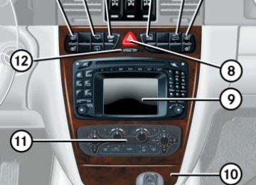
Glove box
1 Unlocked position 2 Locked position 3 Handle
Storage compartments below the arm- rest
Closing small compartment 왘 Lower armrest until it engages in lock.
Storage compartment in front of arm- rest
Controls in detail Useful features
Opening 왘 Slide cover 3 backward.
Closing 왘 Slide cover 3 forward.
Located in the cover of the storage compartment is a storage area for small items such as checks.
Opening large compartment 왘 Press button 2 and lift armrest.
Closing large compartment 왘 Lower armrest until it engages in lock.
In the large storage compartment there is a storage area for up to three CDs.
Opening small compartment 왘 Press button 1 and lift armrest.
191
Controls in detail Useful features
Cup holders
Warning!
The glove box lid also contains cup holders (컄 page 190).
Cup holder in front passenger footwell
Cup holder next to the armrest
왘 Swing bracket 1 upwards until it
clicks into place.
Fold the cup holder closed before mov- ing the front passenger seat fully for- ward.
왘 Place cup holder bracket 1 into re-
cess.
If the cup holder is no longer in use, it can for example, be stored in the storage com- partment below the armrest or in storage pouch on the door panel.
In order to help prevent spilling liquids on vehicle occupants, only use containers that fit into the cup holder. Use lids on open con- tainers and do not fill containers to a height where the contents, especially hot liquids, could spill during braking, vehicle maneu- vers, or in an accident.
When not in use, keep the cup holder closed. An open cup holder may cause injury to you or others when contacted during braking, vehicle maneuvers, or in an acci- dent.
Keep in mind that objects placed in the cup holder may come loose during braking, vehi- cle maneuvers, or in an accident and be thrown around in the vehicle interior. Ob- jects thrown around in the vehicle interior may cause an accident and/or serious per- sonal injury.
192
Cup holder in rear passenger footwell
Before folding the seat backrest for- ward and the rear seat bench down, be sure that all containers in the rear cup holder are removed.
Parcel net in front passenger footwell A small convenience parcel net is located in the front passenger footwell. It is for small and light items, such as road maps, mail, etc.
Warning!
Do not place heavy or fragile objects, or ob- jects having sharp edges in the parcel net.
In an accident, during hard braking or sud- den maneuvers, they could be thrown around inside the vehicle and cause injury to vehicle occupants.
When large objects are stored in the parcel net, do not slide the seat fully forward, it could damage them.
Controls in detail Useful features
Storage bags Storage bags are located on the rear side of the front seats.
Warning!
Do not place heavy or fragile objects, or ob- jects having sharp edges in the storage bags.
In an accident, during hard braking or sud- den maneuvers, they could be thrown around inside the vehicle and cause injury to vehicle occupants.
193
Controls in detail Useful features
Ashtrays
Removing the ashtray insert
Center console ashtray
Warning!
왘 Press sliding knob 4 to the right. The insert will protrude a short-dis- tance.
Remove ashtray only with vehicle standing still. Turn off the engine and set the parking brake. Otherwise the vehicle might move as a result of unintended contact with the gear selector lever.
왘 Remove insert 5 in direction of arrow.
Reinstalling the ashtray insert 왘 Press the insert into the frame until it
snaps into place.
1 Ashtray 2 Cigarette lighter 3 Cover plate
Opening ashtray 왘 Briefly push the cover plate 3.
The ashtray opens automatically.
4 Sliding knob 5 Astray insert
194
Rear passenger compartment
Cigarette lighter
The lighter socket can be used to accom- modate electrical accessories up to a maximum of 180 W.
1 Cover 2 Catch 3 Ashtray insert
Opening ashtray 왘 Pull at top of cover 1.
Removing the ashtray insert 왘 Push down on catch 2. 왘 Pull out the ashtray insert 3.
Reinstalling the ashtray insert 왘 Position the insert and close the cover.
1 Cigarette lighter 왘 Briefly touch the cover plate.
The ashtray opens automatically.
왘 Switch on the ignition (컄 page 35). 왘 Push in cigarette lighter 1.
The lighter will pop out automatically when hot.
Controls in detail Useful features
Warning!
Never touch the heating element or sides of the lighter; they are extremely hot. Hold the knob only.
When leaving the vehicle, always remove the SmartKey from the starter switch, take it with you, and lock the vehicle. Do not leave children unattended in the vehicle, or with access to an unlocked vehicle. Unsuper- vised use of vehicle equipment may cause an accident and/or serious personal injury.
195
왘 Switch on the ignition (컄 page 35). 왘 Flip up cover and insert electrical plug
(cigarette lighter type). The electrical outlet can be used to ac- commodate electrical consumers (e.g. air pump, auxiliary lamps) up to a max- imum of 180 W.
Floormats
Warning!
Whenever you are using floormats, make sure there is enough clearance and the floormats are securely fastened.
Floormats should always be securely fas- tened using the eyelets and retainer pins.
Before driving off, check that the floormats are securely in place and adjust them if nec- essary. A loose floormat could slip and hinder proper functioning of the pedals.
Controls in detail Useful features
Electrical outlet
Electrical outlet in the rear passenger footwell
Electrical outlet on the left side (driver’s side) of the cargo compartment
196
Telephone*
Warning!
Never operate radio transmitters equipped with a built-in or attached antenna (i.e. with- out being connected to an external antenna) from inside the vehicle while the engine is running. Doing so could lead to a malfunc- tion of the vehicle’s electronic system, pos- sibly resulting in an accident and/or personal injury.
Radio transmitters, such as a portable tele- phone or a citizens band unit, should only be used inside the vehicle if they are con- nected to an antenna that is installed on the outside of the vehicle. The external antenna must be approved by Mercedes-Benz. Please contact an autho- rized Mercedes-Benz Light Truck Center for information on the installation of an ap- proved external antenna. Refer to the radio transmitter operation instructions regard- ing use of an external antenna.
Warning!
Please do not forget that your primary re- sponsibility is to drive the vehicle. A driver’s attention to the road must always be his/her primary focus when driving. For your safety and the safety of others, we rec- ommend that you pull over to a safe location and stop before placing or taking a tele- phone call. If you choose to use the telephone1 while driving, please use the hands-free device and only use the telephone when road, traf- fic and weather conditions permit. Some ju- risdictions prohibit the driver from using a cellular telephone while driving a vehicle.
Only operate the COMAND (Cockpit Management and Data System)1 if road, traffic and weather conditions permit.
Bear in mind that at a speed of just 30 mph (approximately 50 km/h), your vehicle is covering a distance of 44 feet (approximately 14 m) every second.
1 Observe all legal requirements
Controls in detail Useful features
You can take and place telephone calls using the s and t buttons on the multifunction steering wheel. Use the con- trol system for performing other telephone functions (컄 page 145). See separate instruction manual for infor- mation on how to operate the telephone.
197
Controls in detail Useful features
Tele Aid
The initial activation of the Tele Aid sys- tem may only be performed by com- pleting the subscriber agreement and placing an acquaintance call using the SOS button. Failure to complete either of these steps will result in a system that is not activated. If the system is not activated, the indicator lamp in the SOS button stays on after switching on ignition and the message TELE AID EMERG. CALL – NOT ACTIVATED will be shown in the multifunction display for approx. 10 seconds. If you have any questions regarding ac- tivation, please call the Response Center at 1-800-756-9018 (in the USA) or 1-888-923-8367 (in Canada).
198
The Tele Aid system (Telematic Alarm Identification on Demand) The Tele Aid system consists of three types of response: 앫 Automatic and manual emergency 앫 Roadside Assistance and 앫 Information The Tele Aid system is operational provid- ing that the vehicle’s battery is charged, properly connected, not damaged and cel- lular and GPS coverage is available. The speaker volume of a Tele Aid call can be adjusted when using the volume control on the multifunction steering wheel. To raise, press button æ and to lower, press button ç. 왘 To activate, press the SOS button, the
Roadside Assistance button • or the Information button ¡, depend- ing on the type of response required.
The SOS button is located above the in- terior rear view mirror. The Roadside Assistance button • and the Information button ¡ are located below the center armrest cover.
Shortly after the completion of your ac- quaintance call, you will receive a user ID and password. By visiting www.mbusa.com and selecting “Tele Aid” (USA only), you will have access to account information, remote door un- lock, profile and more.
The Tele Aid system utilizes the cellular network for communication and the GPS (Global Positioning System) satel- lites for vehicle location. If either of these signals are unavailable, the Tele Aid system may not function and if this occurs, assistance must be sum- moned by other means.
System self-check Initially, after switching on ignition, mal- functions are detected and indicated (the indicator lamps in the SOS button, the Roadside Assistance button • and the Information button ¡ stay on longer than 10 seconds or do not come on). The message TELE AID – DRIVE TO WORKSHOP! appears for approx. ten seconds in the multifunction display.
Controls in detail Useful features
Warning!
If the indicator lamps in the SOS button, in the Roadside Assistance button and/or in the Information button do not come on dur- ing the system self-check or if any of these indicators remain illuminated constantly in red and/or the message TELE AID - DRIVE TO WORKSHOP is displayed in the multifunction display after the system self-check, a malfunction in the system has been detected.
If a malfunction is indicated as outlined above, the system may not operate as ex- pected. Have the system checked at the nearest Mercedes-Benz Light Truck Center as soon as possible.
Emergency calls An emergency call is initiated automatically: 앫 following an accident in which the
emergency tensioning devices (ETDs) or airbags deploy
앫 if the anti-theft alarm or the tow-away
alarm stays on for more than 20 seconds. See anti-theft alarm sys- tem (컄 page 88) and tow-away alarm (컄 page 89)
An emergency call can also be initiated manually by opening the cover next to the interior rear view mirror labeled SOS, then briefly pressing the button located under the cover. See below for instructions on initiating an emergency call manually.
199
Controls in detail Useful features
Once the emergency call is in progress, the indicator lamp in the SOS button will begin to flash. The message EMERGENCY CALL – CONNECTING CALL appears in the multifunc- tion display. When the connection is estab- lished, the message EMERGENCY CALL – CALL CONNECTED appears in the multifunction display. All information rele- vant to the emergency, such as the loca- tion of the vehicle (determined by the GPS satellite location system), vehicle model, identification number and color are gener- ated. A voice connection between the Response Center and the occupants of the vehicle will be established automatically soon af- ter the emergency call has been initiated. When a voice connection is established the audio system mutes and the message TELE AID – EMERGENCY CALL ACTIVE ap- pears in the multifunction display.
The Response Center will attempt to deter- mine more precisely the nature of the acci- dent provided they can speak to an occupant of the vehicle. The Tele Aid system is available if: 앫 it has been activated and is operation- al. Activation requires a subscription for monitoring services, connection and cellular air time
앫 the relevant cellular phone network
and GPS signals are available and pass the information on to the Response Center Location of the vehicle on a map is only possible if the vehicle is able to receive signals from the GPS satellite network and pass the information on to the Response Center.
Warning!
If the indicator lamp in the SOS button is il- luminated continuously and there was no voice connection to the Response Center established, then the Tele Aid system could not initiate an emergency call (e.g. the rele- vant cellular phone network is not available). The message EMERGENCY CALL – CALL FAILED appears in the multifunction display for approx. 10 seconds.
Should this occur, assistance must be sum- moned by other means.
200
Initiating an emergency call manually
왘 Wait for a voice connection to the
Response Center.
왘 Close the cover 1 after the emergency call is concluded.
Warning!
If you feel at any way in jeopardy when in the vehicle (e.g. smoke or fire in the vehicle, ve- hicle in a dangerous road location), please do not wait for voice contact after you have pressed the emergency button. Carefully leave the vehicle and move to a safe loca- tion. The Response Center will automatically contact local emergency officials with the vehicle’s approximate location if they re- ceive an automatic SOS signal and cannot make voice contact with the vehicle occu- pants.
1 Cover 2 SOS button 왘 Briefly press on cover 1.
The cover opens.
왘 Press SOS button 2 briefly.
The indicator lamp in SOS button 2 flashes until the emergency call is con- cluded.
Controls in detail Useful features
Roadside Assistance button • Located below the center armrest cover is the Roadside Assistance button •. 왘 Press and hold the button (for longer
컄컄
than two seconds). A call to a Mercedes-Benz Roadside Assistance dispatcher will be initiated. The button will flash while the call is in progress. The message CONNECTING CALL will appear in the multifunction display.
When the connection is established, the message CALL CONNECTED appears in the multifunction display. The Tele Aid system will transmit data generating the vehicle identification number, model, color and location (subject to availability of cellular and GPS signals). A voice connection between the Roadside Assistance dispatcher and the occupants of the vehicle will be established. When a voice connection is established the audio
201
Controls in detail Useful features
컄컄
system mutes and the message TELE AID – ROADSIDE ASSISTANCE CALL ACTIVE appears in the multifunction display. 왘 Describe the nature of the need for
assistance.
The Mercedes-Benz Roadside Assistance dispatcher will either dispatch a qualified Mercedes-Benz technician or arrange to tow your vehicle to the nearest Mercedes-Benz Light Truck Center. For services such as labor and/or towing, charges may apply. Refer to the Roadside Assistance manual for more information. The following is only available in the USA: 앫 Sign and Drive services: Services such as jump start, a few gallons of fuel or the replacement of a flat tire with the vehicle spare tire are obtainable.
202
The indicator lamp in the Roadside Assistance button • remains illumi- nated in red for approx. ten seconds during the system self-check after switching on ignition (together with the SOS button and the Information button ¡). See system self-check (컄 page 199) when the indicator lamp does not come on in red or stays on longer than ap- proximately ten seconds. If the indicator lamp in the Roadside Assistance button • is illuminated continuously and there was no voice connection to the Response Center established, then the Tele Aid system could not initiate a Roadside Assistance call (e.g. the relevant cellu- lar phone network was not available). The message CALL FAILED appears in the multifunction display.
Roadside Assistance calls can be ter- minated using the t button on the multifunction steering wheel.
Information button ¡ Located below the center armrest cover is the Information button ¡. 왘 Press and hold the button (for longer
than two seconds). A call to the Customer Assistance Center will be initiated. The button will flash while the call is in progress. The message INFO – CONNECTING CALL will appear in the multifunction display.
When the connection is established, the message INFO – CALL CONNECTED appears in the multifunction display. The Tele Aid system will transmit data generating the vehicle identification number, model, color and location (subject to availability of cel- lular and GPS signals).
A voice connection between the Customer Assistance Center representative and the occupants of the vehicle will be estab- lished. When a voice connection is estab- lished the audio system mutes and the message TELE AID – INFO CALL ACTIVE appears in the multifunction display. Infor- mation regarding the operation of your ve- hicle, the nearest Mercedes-Benz Light Truck Center or Mercedes-Benz USA prod- ucts and services is available to you. For more details concerning the Tele Aid system, please visit www.mbusa.com and use your ID and password (sent to you sep- arately) to learn more (USA only).
The indicator lamp in the Information button ¡ remains illuminated in red for approx. ten seconds during the sys- tem self-check after switching on igni- tion (together with the SOS button and the Roadside Assistance button •).
See system self-check (컄 page 199) when the indicator lamp does not come on in red or stays on longer than ap- proximately ten seconds. If the indicator lamp in the Information button ¡ is illuminated continuous- ly and there was no voice connection to the Response Center established, then the Tele Aid system could not initiate an Information call (e.g. the relevant cellular phone network is not avail- able). The message INFO – CALL FAILED appears in the multifunc- tion display. Information calls can be terminated us- ing the t button on the multifunc- tion steering wheel.
Controls in detail Useful features
If the indicator lamps do not start flash- ing after pressing one of the buttons or remain illuminated (in red) at any time, the Tele Aid system has detected a fault or the service is not currently ac- tive, and may not initiate a call. Visit an Mercedes-Benz Light Truck Center and have the system checked or contact the Response Center at 1-800-756-9018 (in the USA) or 1-888-923-8367 (in Canada) as soon as possible.
203
Controls in detail Useful features
Upgrade Signals The Tele Aid system processes calls using the following priority. 앫 Automatic emergency – First priority 앫 Manual emergency – Second priority 앫 Roadside Assistance – Third priority 앫 Information – Fourth priority Should a higher priority call be initiated while you are connected, an upgrade (al- ternating) tone will be heard and the ap- propriate indicator lamp will flash. If certain information such as vehicle identi- fication number or customer information is not available, the operator may need to re- transmit. During this time you will hear a beep and voice contact will be interrupted. Voice contact will resume once the retransmis- sion is completed. Once a call is conclud- ed, a beep will be heard and the appropriate indicator lamp will stop flash- ing. The COMAND system operation will resume.
204
When a Tele Aid call has been initiated, the COMAND system audio is muted and the selected mode (radio or CD) pauses. The optional cellular phone (if installed) switches off. If you must use this phone, the vehicle must be parked. Disconnect the coiled cord and place the call. The navigation system (if en- gaged) will continue to run. The display in the instrument cluster is available for use and spoken commands are only available by pressing the RPT button on the COMAND unit. A pop-up window will appear in the COMAND display to indicate that a Tele Aid call is in progress.
If the indicator lamp continues to flash or the system does not reset, contact the Response Center at 1-800-756-9018 (in the USA) or 1-888-923-8367 (in Canada), or Mercedes-Benz Customer Assistance at 1-800-FOR-MERCedes (1-800-367-6372) in the USA or Customer Service at 1-800-387-0100 in Canada.
The indicator lamp in the respective button flashes until the call is conclud- ed. Calls can only be terminated by a Response Center or Customer Assistance Center representative, ex- cept Roadside Assistance and Information calls, which can also be terminated by pressing button t on the multifunction steering wheel.
Remote door unlock In case you have locked your vehicle unin- tentionally (e.g. SmartKey inside vehicle), and the reserve key is not handy: 왘 Contact the Mercedes-Benz Response Center at 1-800-756-9018 (in the USA) or 1-888-923-8367 (in Canada). You will be asked to provide your pass- word which you provided when you completed the subscriber agreement. 왘 Then return to your vehicle and press
the tailgate lock for minimum of 20 seconds until the SOS button is flashing. The message EMERGENCY CALL – CALL CONNECTED appears in the multi- function display.
As an alternative, you may unlock the vehi- cle via Internet using the ID and password sent to you shortly after the completion of your acquaintance call.
The Response Center will then unlock your vehicle with the remote door unlocking feature. The remote door unlock feature is avail- able if the relevant cellular phone net- work is available. The SOS button will flash and the mes- sage EMERGENCY CALL – CALL CONNECTED will appear in the mul- tifunction display to indicate receipt of the door unlock command. Once the vehicle is unlocked, a Response Center specialist will at- tempt to establish voice contact with the vehicle occupants. If the tailgate lock was pressed for more than 20 seconds before door un- lock authorization was received by the Response Center, you must wait 15 minutes before pressing the tailgate lock again.
Controls in detail Useful features
Stolen Vehicle Recovery services In the event your vehicle was stolen: 왘 Report the incident to the police.
The police will issue a numbered inci- dent report.
왘 Pass this number on to the
Mercedes-Benz Response Center along with your password issued to you when you subscribed to the service. The Response Center will then attempt to covertly contact the vehicle’s Tele Aid system. Once the vehicle is lo- cated, the Response Center will con- tact the local law enforcement and you. The vehicle’s location will only be pro- vided to law enforcement.
205
Controls in detail Useful features
Garage door opener
The built-in remote control is capable of operating up to three separately controlled devices, for example garage door openers, gate openers, or other devices compatible with HomeLink® or some other systems. You can program the signal transmitter buttons.
Remote control integrated into the interior rear view mirror
Indicator lamp
2 3 4 Signal transmitter button
Hand-held transmitter button Hand-held remote control trans- mitter (not part of the vehicle equipment)
206
Warning!
Before programming the integrated remote control to a garage door opener or gate op- erator, make sure people and objects are out of the way of the device to prevent po- tential harm or damage. When programming a garage door opener, the door moves up or down. When programming a gate operator, the gate opens or closes.
Do not use the integrated remote control with any garage door opener that lacks safe- ty stop and reverse features as required by U.S. federal safety standards (this includes any garage door opener model manufac- tured before April 1, 1982). A garage door that cannot detect an object - signaling the door to stop and reverse - does not meet current U.S. federal safety standards.
Controls in detail Useful features
Certain types of garage door openers are incompatible with the integrated opener. If you should experience diffi- culties with programming the transmit- ter, contact an authorized Mercedes-Benz Light Truck Center, or call Mercedes-Benz Customer Assistance Center (in the USA only) at 1-800-FOR-MERCedes, or Customer Service (in Canada) at 1-800-387-0100.
USA only: This device complies with Part 15 of the FCC Rules. Operation is subject to the following two conditions: (1) This device may not cause harmful
interference, and
Canada only: This device complies with RSS-210 of Industry Canada. Operation is subject to the following two conditions: (1) This device may not cause interfer-
ence, and
(2) this device must accept any inter-
(2) this device must accept any inter-
ference received, including interfer- ence that may cause undesired operation.
ference received, including interfer- ence that may cause undesired operation of the device.
Any unauthorized modification to this device could void the user’s authority to operate the equipment.
Any unauthorized modification to this device could void the user’s authority to operate the equipment.
207
Controls in detail Useful features
Programming or reprogramming the in- tegrated remote control Step 1: 왘 Switch on the ignition (컄 page 35). Step 2: 왘 If you have previously programmed an
integrated signal transmitter button and wish to retain its programming, proceed to step 3. Otherwise, press and hold the two outer signal transmit- ter buttons 2 and 4 and release them only when the indicator lamp 1 begins to flash after approximately 20 seconds (do not hold the button for longer than 30 seconds). This proce- dure erases any previous settings for all three channels and initializes the memory. If you later wish to program a second and/or third hand-held trans- mitter to the remaining two signal transmitter buttons, do not repeat this step and begin directly with step 3.
208
Step 3: 왘 Hold the end of the hand-held remote
control transmitter 6 of the device you wish to train approximately 2 to 5 in (5 to12 cm) away from the surface of the integrated remote control locat- ed on the interior rear view mirror, keeping the indicator lamp 1 in view.
Step 4: 왘 Using both hands, simultaneously
press the hand-held transmitter button 5 and the desired integrated signal transmitter button (2, 3 or 4). Do not release the buttons until completing step 5. The indicator lamp 1 on the integrat- ed remote control will flash, first slowly and then rapidly.
The indicator lamp 1 flashes the first time the signal transmitter button is programmed. If this button has already been programmed, the indicator lamp will only start flashing after 20 sec- onds.
Step 5: 왘 When the indicator lamp 1 flashes
rapidly, release both buttons.
Step 6: 왘 Press and hold the just-trained inte- grated signal transmitter button and observe the indicator lamp 1. If the indicator lamp 1 stays on con- stantly, programming is complete and your device should activate when the integrated signal transmitter button is pressed and released.
Controls in detail Useful features
If the indicator lamp 1 blinks rapidly for about two seconds and then turns to a constant light, continue with pro- gramming steps 8 through 12 as your garage door opener may be equipped with the “rolling code” feature.
Step 7: 왘 To program the remaining two buttons,
repeat the steps above starting with step 3.
Rolling code programming To train a garage door opener (or other roll- ing code devices) with the rolling code fea- ture, follow these instructions after completing the “Programming” portion (steps 1 through 6) of this text. (A second person may make the following training procedures quicker and easier.) Step 8: 왘 Locate “training” button on the garage
door opener motor head unit.
Exact location and color of the button may vary by garage door opener brand. Depending on manufacturer, the “train- ing” button may also be referred to as “learn”or “smart” button. If there is dif- ficulty locating the transmitting button, refer to the garage door opener opera- tor’s manual.
Step 9: 왘 Press “training” button on the garage
door opener motor head unit. The “training light” is activated.
You have 30 seconds to initiate the follow- ing step. Step 10: 왘 Firmly press, hold for two seconds and
release the programmed integrated signal transmitter button (2, 3 or 4).
Step 11: 왘 Press, hold for two seconds and re- lease same button a second time to complete the training process.
Some garage door openers (or other rolling code equipped devices) may require you to perform this procedure a third time to complete the training. Step 12: 왘 Confirm the garage door operation by pressing the programmed integrated signal transmitter button (2, 3 or 4).
Step 13: 왘 To program the remaining two buttons,
repeat the steps above starting with step 3.
Gate operator/Canadian programming Canadian radio-frequency laws require transmitter signals to “time-out” (or quit) after several seconds of transmission which may not be long enough for the inte- grated signal transmitter to pick up the sig- nal during programming. Similar to this Canadian law, some U.S. gate operators are designed to “time-out” in the same manner.
209
Controls in detail Useful features
If you live in Canada or if you are having dif- ficulties programming a gate operator (re- gardless of where you live) by using the programming procedures, replace step 4 with the following: Step 4: 왘 Continue to press and hold the inte- grated signal transmitter button (2, 3 or 4) while you press and re-press (“cycle”) your hand-held remote con- trol transmitter 6 every two seconds until the frequency signal has bee- learned. Upon successful training, the indicator lamp 1 will flash slowly and then rapidly after several seconds.
왘 Proceed with programming step 5 and
step 6 to complete.
210
Operation of integrated remote control 왘 Switch on the ignition (컄 page 35). 왘 Select and press the appropriate inte- grated signal transmitter button (2, 3 or 4) to activate the remote con- trolled device. The integrated remote control trans- mitter continues to send the signal as long as the button is pressed – up to 20 seconds.
Erasing the integrated remote control memory 왘 Switch on the ignition (컄 page 35). 왘 Simultaneously hold down the signal transmitter buttons 2 and 4, for ap- proximately 20 seconds, until the indi- cator lamp 1 blinks rapidly. Do not hold for longer than 30 seconds. The codes of all three channels are erased.
If you sell your vehicle, erase the codes of all three channels.
Reprogramming a single integrated sig- nal transmitter button To program a device using a signal trans- mitter button previously trained, follow these steps: 왘 Press and hold the desired signal trans- mitter button (2, 3 or 4). Do not re- lease the button.
왘 The indicator lamp will begin to flash af- ter 20 seconds. Without releasing the integrated signal transmitter button, proceed with programming starting with step 3.
Heated steering wheel
The steering wheel heater warms up the leather area of the steering wheel. The lever with the heated steering wheel switch is on the lower left-hand side of the steering wheel.
Switching on 왘 Switch on the ignition (컄 page 35). All lamps in the instrument cluster come on.
왘 Turn switch at the tip of lever in direc-
tion of arrow 1. The steering wheel is heated. Indicator lamp 3 comes on.
1 Switching on 2 Switching off 3 Indicator lamp
Controls in detail Useful features
Switching off 왘 Turn switch at the tip of lever in direc-
tion of arrow 2. The steering wheel heater is turned off. Indicator lamp 3 goes out. The steering wheel heating switches off automatically while indicator lamp 3 remains on when the temperature of 앫 the vehicle interior is above 86°F
(30°C)
앫 the steering wheel is above
82°F (28°C)
Indicator lamp 3 flashes or switches off in case of 앫 power surge or undervoltage 앫 a steering wheel heating
malfunction
211
212
Operation The first 1000 miles (1500 km)
Driving instructions
At the gas station
Engine compartment
Battery
Tires and wheels
Winter driving
Maintenance
Vehicle care
213
Operation The first 1000 miles (1500 km)
In the “Operation” section you will find de- tailed information on operating, maintain- ing and caring for your vehicle.
214
Additional instructions for AMG vehi- cles: 앫 During the first 1000 miles
(1500 km), do not exceed a speed of 85 mph (140 km/h).
앫 During this period, avoid engine speeds above 4500 rpm in each gear.
The more cautiously you treat your vehicle during the break-in period, the more satis- fied you will be with its performance later on. 앫 Drive your vehicle during the first
1000 miles (1500 km) at varying but moderate vehicle and engine speeds. 앫 During this period, avoid heavy loads (full throttle driving) and excessive en- gine speeds (no more than 2/3 of maxi- mum rpm in each gear).
앫 Avoid accelerating by kick-down. 앫 Do not attempt to slow the vehicle
down by shifting to a lower gear using the gear selector lever.
앫 Select positions 3, 2 or 1 only when driving at moderate speeds (for hill driving).
After 1000 miles (1500 km) you may grad- ually increase vehicle and engine speeds to the permissible maximum.
All of the above instructions, as may apply to your vehicle type, also apply when driv- ing the first 1000 miles (1500 km) after the engine, the transfer case, the front differ- ential or the rear differential has been re- placed. Always obey applicable speed limits.
G 55 AMG: For better protection of the front and rear differential, the oil must be changed after a break-in period of 1900 miles (3000 km). Changing oil in the front and rear differential increases the service life and helps reduce noise from the differential locks. See Maintenance Booklet for additional information and Factory Approved Service Products pamphlet for informa- tion on the approved service product required to perform the front and rear axle oil change.
Operation The first 1000 miles (1500 km)
215
Operation Driving instructions
Drive sensibly – save fuel
Drinking and driving
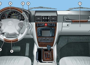
Pedals
Warning!
Warning!
Keep driver’s foot area clear at all times. Ob- jects stored in this area may impair pedal movement.
Drinking and driving and/or taking drugs and driving are very dangerous combina- tions. Even a small amount of alcohol or drugs can affect your reflexes, perceptions and judgement.
The possibility of a serious or even fatal ac- cident are greatly increased when you drink or take drugs and drive.
Do not drink or take drugs and drive or allow anyone to drive who has been drinking or taking drugs.
Fuel consumption, to a great extent, de- pends on driving habits and operating conditions. To save fuel you should: 앫 Keep tires at the recommended infla-
tion pressures.
앫 Remove unnecessary loads. 앫 Allow engine to warm up under low
load use.
앫 Avoid frequent acceleration and decel-
eration.
앫 Have all maintenance work performed
at the intervals specified in the Maintenance Booklet and as required by the maintenance service display. Contact an authorized Mercedes-Benz Light Truck Center.
Fuel consumption is also increased by driv- ing in cold weather, in stop-and-go traffic, on short trips and in hilly area.
216
Power assistance
Warning!
With the engine not running, there is no power assistance for the brake and steering systems. In this case, it is important to keep in mind that a considerably higher degree of effort is necessary to brake and steer the ve- hicle.
Brakes
Warning!
After driving in heavy rain for some time without applying the brakes or through wa- ter deep enough to wet brake components or salty road conditions, the first braking ac- tion may be somewhat reduced and in- creased pedal pressure may be necessary to obtain expected braking effect. Maintain a safe distance from vehicles in front.
Resting your foot on the brake pedal will cause excessive and premature wear of the brake pads.
It can also result in the brakes overheating, thereby significantly reducing their effec- tiveness. It may not be possible to stop the vehicle in sufficient time to avoid an acci- dent.
To help prevent brake disk corrosion after driving on wet road surfaces (particularly salted roads), it is advisable to brake the vehicle with considerable force prior to parking. The heat generated serves to dry the brakes. If your brake system is normally only sub- jected to moderate loads, you should occa- sionally test the effectiveness of the brakes by applying above-normal braking pressure at higher speeds. This will also enhance the grip of the brake pads.
Operation Driving instructions
Be very careful not to endanger other road users when you apply the brakes. Refer to the description of the Brake Assist System (BAS) (컄 page 82).
If the parking brake is released and the brake warning lamp in the instrument clus- ter stays on and there is no audible warn- ing (EBB), the brake fluid level in the reservoir is too low. Brake pad wear or a leak in the system may be the reason for low brake fluid in the res- ervoir. Have the brake system inspected immediately. Contact an authorized Mercedes-Benz Light Truck Center. All checks and service work on the brake system should be carried out by qualified technicians only. Contact an authorized Mercedes-Benz Light Truck Center. Install only brake pads and brake fluid recommended by Mercedes-Benz.
217
Operation Driving instructions
Warning!
Driving off
Apply the brakes to test them briefly after driving off. Perform this procedure only when the road is clear of other traffic. Warm up the engine smoothly. Do not place full load on the engine until the oper- ating temperature has been reached. When starting off on a slippery surface, do not allow a drive wheel to spin for an ex- tended period with the ESP switched off. Doing so may cause serious damage to the drivetrain which is not covered by the Mercedes-Benz Limited Warranty. To ensure sufficient traction during off-road driving, activate differential locks as needed (컄 page 158).
If other than recommended brake pads are installed, or other than recommended brake fluid is used, the braking properties of the vehicle can be degraded to an extent that safe braking is substantially impaired. This could result in an accident.
When driving down long and steep grades, relieve the load on the brakes by selecting gear range 3, 2 or 1 on the automatic transmission to use the engine’s braking power (컄 page 150). This helps prevent overheating of the brakes and reduces brake pad wear.
After hard braking, it is advisable to drive on for some time, rather than immediately parking, so the air stream will cool down the brakes faster.
218
Parking
Warning!
Do not park this vehicle in areas where com- bustible materials such as grass, hay or leaves can come into contact with the hot exhaust system, as these materials could be ignited and cause a vehicle fire.
To reduce the risk of personal injury as a re- sult of vehicle movement, before turning off the engine and leaving the vehicle always: 앫 Keep right foot on brake pedal. 앫 Pull the parking brake lever up as many
notches as possible.
앫 Move the selector lever to position P. 앫 Slowly release brake pedal. 앫 When parked on an incline, turn front
wheel towards the road curb.
앫 Turn the SmartKey in the starter switch to position 0 and remove the SmartKey from the starter switch.
앫 Take the SmartKey and lock vehicle
when leaving.
Set the parking brake whenever park- ing or leaving the vehicle. In addition, move gear selector lever to position P. In addition, when parking on hills turn front wheel towards the road curb.
Operation Driving instructions
Tires
Warning!
The treadwear indicator appears as a solid band across the tread.
Warning!
If you feel a sudden significant vibration or ride disturbance, or you suspect that possi- ble damage to your vehicle has occurred, you should turn on the hazard warning flash- ers, carefully slow down, and drive with cau- tion to an area which is a safe distance from the road.
Inspect the tires and the vehicle underbody for possible damage. If the vehicle or tires appear unsafe, have it towed to the nearest Mercedes-Benz Light Truck Center or tire dealer for repairs.
Treadwear indicators (TWI) are required by law. These indicators are located in six places on the tread circumference and be- come visible at a tread depth of approxi- mately 1/16 in (1.6 mm), at which point the tire is considered worn and should be replaced.
Although the applicable federal motor vehi- cle safety laws consider a tire to be worn when the treadwear indicators (TWI) be- come visible at approximately 1/16 in (1.6 mm), we recommend that you do not al- low your tires to wear down to that level. As tread depth approaches 1/8 in (3.0 mm), the adhesion properties on a wet road are sharply reduced.
Depending upon the weather and/or road surface (conditions), the tire traction varies widely.
Specified tire inflation pressures must be maintained. This applies particularly if the tires are subject to high loads (e.g. high speeds, heavy loads, high ambient temper- atures).
219
Operation Driving instructions
Warning!
Tire traction
Do not drive with a flat tire. A flat tire affects the ability to steer or brake the vehicle. You may lose control of the vehicle. Continued driving with a flat tire or driving at high speed with a flat tire will cause excessive heat build-up and possibly a fire.
Hydroplaning
Depending on the depth of the water layer on the road, hydroplaning may occur even at low speeds and with new tires. Reduce vehicle speed, avoid track grooves in the road and apply brakes cautiously in the rain.
The safe speed on a wet, snow covered or icy road is always lower than on a dry road. You should pay particular attention to the condition of the road whenever the outside temperatures are close to the freezing point.
Warning!
If ice has formed on the road, tire traction will be substantially reduced. Under such weather conditions, drive, steer and brake with extreme caution.
Mercedes-Benz recommends M+S rated radial-ply tires with a minimum tread depth of approximately 1/6 in (4 mm) for the win- ter season for all four wheels to ensure normal balanced handling characteristics. On packed snow, they can reduce your stopping distance as compared with sum- mer tires. Stopping distance, however, is still consid- erably greater than when the road is not covered with snow or ice. Exercise appro- priate caution.
Avoid spinning of a drive wheel. This may cause serious damage to the drivetrain which is not covered by the Mercedes-Benz Limited Warranty.
220
Tire speed rating
Regardless of the tire speed rating, local speed limits should be obeyed. Use pru- dent driving speeds appropriate to prevail- ing conditions.
Warning!
Even when permitted by law, never operate a vehicle at speeds greater than the maxi- mum speed rating of the tires.
Exceeding the maximum speed for which tires are rated can lead to sudden tire fail- ure, causing loss of vehicle control and pos- sibly resulting in an accident and/or serious injury and possible death, for you and for others.
Operation Driving instructions
Your vehicle is factory equipped with “V”-rated tires, which have a speed rating of 149 mph (240 km/h). An electronic speed limiter prevents your vehicle from exceeding a speed of 130 mph (210 km/h).
For information on speed rating for winter tires, see “Winter driving” (컄 page 275). For additional general information on tire speed markings on tire sidewall, see “Tire speed rating” (컄 page 273).
Winter driving instructions
The most important rule for slippery or icy roads is to drive sensibly and to avoid abrupt acceleration, braking and steering maneuvers. Do not use the cruise control system under such conditions. When the vehicle is in danger of skidding, move gear selector lever to position N. Try to keep the vehicle under control by cor- rective steering action.
For information on driving with snow chains, see “Snow chains” (컄 page 276).
Warning!