- 2009 Mercedes-Benz CLK Class Coupe Owners Manuals
- Mercedes-Benz CLK Class Coupe Owners Manuals
- 2004 Mercedes-Benz CLK Class Coupe Owners Manuals
- Mercedes-Benz CLK Class Coupe Owners Manuals
- 2008 Mercedes-Benz CLK Class Coupe Owners Manuals
- Mercedes-Benz CLK Class Coupe Owners Manuals
- 2007 Mercedes-Benz CLK Class Coupe Owners Manuals
- Mercedes-Benz CLK Class Coupe Owners Manuals
- 2005 Mercedes-Benz CLK Class Coupe Owners Manuals
- Mercedes-Benz CLK Class Coupe Owners Manuals
- 2003 Mercedes-Benz CLK Class Coupe Owners Manuals
- Mercedes-Benz CLK Class Coupe Owners Manuals
- 2006 Mercedes-Benz CLK Class Coupe Owners Manuals
- Mercedes-Benz CLK Class Coupe Owners Manuals
- Download PDF Manual
-
Be especially careful when small children are around. To stop the closing procedure, do one of the following: 앫 press KEYLESS-GO locking/closing
switch 1
앫 press trunk closing switch 앫 press the Š button on the SmartKey
with KEYLESS-GO
앫 press the remote trunk opening or clos-
ing switch (on driver’s door)
118
Even with the SmartKey with KEYLESS-GO removed from the vehicle, the trunk closing switch can be operated. Therefore, do not leave children unattended in the vehicle, or with access to an unlocked vehicle. Unsu- pervised use of vehicle equipment may cause an accident and/or serious personal injury.
Warning!
Only drive with the trunk closed as, among other dangers such as blocked visibility, exhaust fumes may enter the vehicle interior.
Trunk emergency release
With the emergency release button, the trunk can be opened from inside the trunk. The emergency release button is located on the inside of the trunk lid.
1 Emergency release button 왘 Briefly press emergency release
button 1. The trunk unlocks and opens slightly.
왘 Push up the trunk lid to fully open.
i The emergency release button unlocks and opens the trunk while the vehicle is standing still or in motion.
Illumination of the emergency release but- ton: 앫 The button will flash for 30 minutes
after opening the trunk.
앫 The button will flash for 60 minutes
after closing the trunk.
The emergency release button does not open the trunk if the vehicle battery is discharged or disconnected.
If the trunk does not open, it is still locked separately (컄 page 119).
If the vehicle has previously been locked using the SmartKey or KEYLESS-GO*, opening the trunk from the inside using the emergency release button will trigger the anti-theft alarm system. To cancel the alarm, do one of the following: 앫 Insert the SmartKey in the starter
switch.
앫 Press button ‹ or Œ on the
SmartKey.
In vehicles with KEYLESS-GO*: 앫 Pull an outside door handle.
The SmartKey with KEYLESS-GO* must be within 3 ft (1 m) of the ve- hicle.
앫 Press the KEYLESS-GO* start/stop
button (컄 page 35). The SmartKey with KEYLESS-GO* must be inside the vehicle.
Controls in detail Locking and unlocking
Valet locking
To deny any unauthorized person ac- cess to the trunk, e.g. when you valet park the vehicle, lock it separately with the mechanical key. Leave only the SmartKey or SmartKey with KEYLESS-GO* less its mechanical key with the vehicle.
The lock is located next to the handle above the rear license plate recess.
1 Neutral position 2 Locked
컄컄
119
Controls in detail Locking and unlocking
컄컄
왘 Close the trunk (컄 page 113). 왘 Pull the mechanical key out of the
SmartKey (컄 page 404).
왘 Insert the mechanical key in the trunk
lid lock.
왘 Turn the mechanical key clockwise to position 2 and remove the mechani- cal key in that position to lock the trunk.
The trunk remains locked even when the vehicle is centrally unlocked.
You can only cancel the separate trunk locking mode by means of the mechanical key.
왘 Insert the mechanical key in the trunk
lid lock.
왘 Turn the mechanical key counterclock- wise to neutral position 1 and remove the mechanical key in that position to unlock the trunk. You can now open the trunk (컄 page 111).
Automatic central locking
The doors and the trunk automatically lock when the ignition is switched on and the wheels are turning at vehicle speeds of approximately 9 mph (15 km/h) or more. You can open a locked door from the inside. Open doors only when conditions are safe to do so.
The doors unlock automatically after an accident if the force of the impact exceeds a preset threshold. To prevent the vehicle door locks from locking, deactivate the automatic central locking when the vehicle 앫 is pushed or towed 앫 is on a test stand
You can deactivate the automatic locking mode using the control system, see “Set- ting automatic locking” (컄 page 163).
120
Locking and unlocking from the inside
You can lock or unlock the doors and the trunk from inside using the central locking or unlocking switch. This can be useful, for example, if you want to lock the vehicle before starting to drive. You cannot lock or unlock the fuel filler flap with the central locking or unlocking switch.
Warning!
When leaving the vehicle, always remove the SmartKey or SmartKey with KEYLESS-GO* from the starter switch, take it with you, and lock the vehicle. Do not leave children unat- tended in the vehicle, or with access to an unlocked vehicle. Unsupervised use of vehi- cle equipment may cause an accident and/or serious personal injury.
The switches are located in the center console.
1 Central locking switch 2 Central unlocking switch
You can open a locked door from the inside. Open door only when conditions are safe to do so. If the vehicle was previously centrally locked with the SmartKey or the SmartKey with KEYLESS-GO*, it will not unlock using the central unlocking switch 2.
Controls in detail Locking and unlocking
If the vehicle was previously locked with the central locking switch 1
앫 while in the selective remotecontrol mode, only the door opened from inside is unlocked.
앫 while in the global remote control
mode, the complete vehicle is unlocked when a door is opened from the inside.
Locking 왘 Press central locking switch 1.
If both doors are closed, the vehicle locks.
Unlocking 왘 Press central unlocking switch 2.
The vehicle unlocks.
121
Controls in detail Seats
For information on seat adjustment, see “Adjusting” (컄 page 37).
For information on active head restraints, see “Active head restraints” (컄 page 73).
Head restraint height
Front seat active head restraints
Rear seat head restraints
Warning!
Warning!
For your protection, drive only with properly positioned head restraints.
Adjust the head restraint so that it is as close to the head as possible and the center of the head restraint supports the back of the head at eye level. This will reduce the po- tential for injury to the head and neck in the event of an accident or similar situation.
You cannot remove the active head re- straints on the driver’s and passenger’s seat. For removal of the active head restraints we recommend that you contact an authorized Mercedes-Benz Center. For information on head restraint adjust- ment, see “Seats” (컄 page 37).
122
For safety reasons, always drive with the rear head restraints in the upright position when the rear seats are occupied.
Keep the area around head restraints clear of articles (e.g. clothing) to not obstruct the folding operation of the head restraints.
1 Release button Raising: 왘 Manually adjust the height of the head
restraint by pulling it upward. If the head restraint is fully retracted, push release button 1 and pull the head restraint out.
Lowering: 왘 To lower the head restraint, push
release button 1 and push down on the head restraint.
Warning!
Folding head restraints back with re- lease button
Folding head restraints back with switch in the center console
Controls in detail Seats
For your protection, drive only with properly positioned head restraints.
Adjust the head restraint so that it is as close to the head as possible and the center of the head restraint supports the back of the head at eye level. This will reduce the po- tential for injury to the head and neck in the event of an accident or similar situation.
Do not drive the vehicle without the seat head restraints. Head restraints are intended to help reduce injuries during an accident.
1 Release button 왘 Push release button 1.
The head restraints will fold backward.
You can also fold the head restraints back using the switch in the center console.
1 Rear head restraints folding switch 왘 Start the engine (컄 page 48). 왘 Press switch 1 to release the head re-
straints. The head restraints will fold backward.
123
Controls in detail Seats
Placing rear head restraints upright
왘 Press the release button (컄 page 123)
and tilt the head restraint to the desired position.
Removing and installing rear seats head restraints
Warning!
For your protection, drive only with properly positioned head restraints.
Adjust the head restraint so that it is as close to the head as possible and the center of the head restraint supports the back of the head at eye level. This will reduce the po- tential for injury to the head and neck in the event of an accident or similar situation.
Do not drive the vehicle without the seat head restraints. Head restraints are intend- ed to help reduce injuries during an accident.
Do not interchange head restraints from front and rear seat.
1 Release button
Removing rear seat head restraints 왘 Fold back head restraint (컄 page 123). 왘 Pull head restraint to its highest
position.
왘 Push release button 1 and pull out
head restraint.
Installing rear head restraints 왘 Insert head restraint and push it down
until it engages.
왘 Push release button 1 and adjust head restraint to desired position.
왘 Pull the rear head restraint forward un-
til it locks into position.
Warning!
Make sure the head restraints engage when placing them upright. Otherwise their pro- tective function cannot be assured.
Head restraint tilt Two different head restraint angle positions are available.
124
Multicontour seat*
The multicontour seat has a movable seat cushion and inflatable air cushions built into the backrest to provide additional lumbar and side support. The seat cushion movement, backrest cushion height and curvature can be continuously varied with switches on the side of the seat after switching on ignition.
1 Seat cushion depth 2 Backrest bottom 3 Backrest center 4 Side bolster adjustment 왘 Switch on ignition (컄 page 36).
Controls in detail Seats
Seat cushion depth 왘 Adjust the seat cushion depth to the
length of your upper leg using switch 1.
Backrest contour 왘 Adjust the contour of the backrest to the desired position using switches 2 and 3.
Backrest side bolsters 왘 Adjust the backrest side bolsters so
that they provide good lateral support using switch 4.
If, after a period of time, the seat no longer provides the desired contour, then repeat the adjustment procedure.
125
Controls in detail Seats
Seat heating*
Both switches for the front seats are located in the center console.
1 Seat heating switch
126
The red indicator lamps on the switch 1 show which heating level you have select- ed.
Level
off
Three indicator lamps on (highest level). After approximately five minutes, seat heating is automatically switched to level 2. Two indicator lamps on. After approximately ten minutes, seat heating is automatically switched to level 1. One indicator lamp on (lowest level). After approximately 20 minutes, seat heating is automatically switched off. No indicator lamp on.
왘 Switch on the ignition (컄 page 36).
Switching on seat heating 왘 Press seat heating switch 1 once.
Three red indicator lamps in the switch come on.
왘 Continue pressing seat heating
switch 1 until desired seat heating level is reached.
Switching off seat heating 왘 Press seat heating switch 1
repeatedly until all red indicator lamps go out.
If one or more of the indicator lamps on the seat heater switch 1 are flashing, there is insufficient voltage due to too many electrical consumers being switched on. The seat heating switches off automatically. The seat heating will switch back on again automatically as soon as sufficient voltage is available.
Seat ventilation*
Both switches for the front seats are located in the center console.
1 Seat ventilation switch
Controls in detail Seats
The blue indicator lamps in the switch 1 show which ventilation level you have selected:
Level off
Three indicator lamps on Two indicator lamps on One indicator lamp on No indicator lamp on
왘 Switch on the ignition (컄 page 36). All lamps in the instrument cluster come on.
Switching on seat ventilation 왘 Press seat ventilation switch 1.
Three blue indicator lamps come on.
왘 Press seat ventilation switch 1
repeatedly until the desired seat venti- lation level is reached.
The seat ventilation for the driver’s seat is automatically set to the highest level if activated via summer opening feature (컄 page 249).
Switching off seat ventilation 왘 Press seat ventilation switch 1
repeatedly until all blue indicator lamps go out.
If one or more of the indicator lamps on the seat ventilation switch 1 are flash- ing, there is insufficient voltage due to too many electrical consumers being switched on. The seat ventilation switches off automatically. The seat ventilation will switch back on again automatically as soon as sufficient voltage is available.
127
Controls in detail Memory function
Prior to operating the vehicle, the driver should check and adjust the seat height, seat position fore and aft, and seat back- rest angle if necessary, to ensure adequate control, reach and comfort. The head restraint should also be adjusted for proper height. See also the section on air bags (컄 page 63) for proper seat positioning. In addition, adjust the steering wheel to ensure adequate control, reach, operation and comfort. Both the interior and exterior rear view mirrors should be adjusted for adequate rear vision. Fasten seat belts. Infants and small chil- dren should be seated in a properly se- cured restraint system that complies with U.S. Federal Motor Vehicle Safety Standards 213 and 225 and Canadian Motor Vehicle Safety Standards 213 and 210.2.
The following settings are stored when using the buttons on the driver’s door: 앫 Driver’s seat, backrest and head
restraint position
앫 Steering wheel position 앫 Exterior rear view mirror position
Warning!
Do not activate the memory function while driving. Activating the memory function while driving could cause the driver to lose control of the vehicle.
The following settings are stored when us- ing the buttons on the passenger door: 앫 Front passenger seat, backrest and
head restraint position
The memory button and memory position switch are located on the door.
1 Memory button 2 Memory position switch 왘 Switch on the ignition (컄 page 36). or 왘 Open the respective door and insert
the SmartKey in the starter switch.
128
Storing positions into memory
Recalling positions from memory
왘 Adjust the seats, steering wheel and
exterior rear view mirrors to the desired position (컄 page 38).
왘 Turn memory position switch 2 to the
desired memory position. 왘 Press memory button 1. 왘 Release memory button 1 and press
memory position switch 2 within three seconds. All settings are stored to the selected position.
Do not operate the seats using the memory button if the seat backrest is in an excessively reclined position. Doing so could cause damage to front or rear seats. First move the seat backrest to an upright position.
왘 Turn memory position switch 2 to the
desired memory position.
왘 Press and hold memory position
switch 2 until the seat, steering wheel and exterior rear view mirrors have completely moved to the stored positions.
Controls in detail Memory function
Releasing the memory position switch stops movement to the stored positions immediately.
129
Controls in detail Memory function
Storing exterior rear view mirror park- ing position
For easier parking, you can adjust the passenger-side exterior rear view mirror so that you can see the right rear wheel as soon as you engage reverse gear R. For information on activating the parking position feature, see “Setting parking posi- tion for exterior rear view mirror” (컄 page 164) and “Activating exterior rear view mirror parking position” (컄 page 182).
130
왘 Adjust the passenger-side exterior rear view mirror with button 2 so that you see the rear wheel and the road curb.
왘 Press memory button 1. 왘 Within three seconds, press bottom of
adjustment button 2. The parking position is stored if the mirror does not move.
If the mirror does move, repeat the above steps. After the setting is stored you can move the mirror again.
1 Memory button 2 Adjustment button 3 Passenger side exterior rear view
mirror button
왘 Stop the vehicle. 왘 Switch on the ignition (컄 page 36). 왘 Press button 3.
The passenger-side exterior rear view mirror is selected.
왔 Lighting For information on how to switch on the headlamps and use the turn signals, see “Switching on headlamps” (컄 page 52) and “Turn signals” (컄 page 53).
If you drive in countries where vehicles drive on the other side of the road than the country in which the vehicle is reg- istered, you must have the headlamps modified for symmetrical low beams. Relevant information can be obtained at your authorized Mercedes-Benz Center.
Vehicles equipped with active Bi-Xe- non* headlamps: The active Bi-Xenon headlamps monitor your steering angle and driving speed, then automatically shift their beams to either side to bet- ter follow the curvature of the road ahead, increasing usable illumination over conventional headlamps.
Controls in detail Lighting
Exterior lamp switch
M Off
The exterior lamp switch is located on the dashboard to the left of the steering wheel.
Exterior lamp switch
Daytime running lamp mode (컄 page 133)
U Automatic headlamp mode
Daytime running lamp mode (컄 page 133)
C Parking lamps (also tail lamps,
license plate lamps, side marker lamps, instrument panel lamps) B Low beam headlamps (or high
beam headlamps when the combi- nation switch is pushed forward) and parking lamps
ˆ Standing lamps, right (turn left one
stop)
‚ Standing lamps, left (turn left two
stops)
‡ Indicator lamp for front fog lamps † Indicator lamp for rear fog lamp
131
Controls in detail Lighting
With the SmartKey removed from the starter switch or the engine turned off with KEYLESS-GO* and the driver’s door open, a warning sounds if the parking lamps or low beam headlamps are switched on. The message Turn off lamps appears in the multifunction display.
Manual headlamp mode The low beam headlamps and the parking lamps can be switched on and off with the exterior lamp switch.
Automatic headlamp mode The following lamps switch on and off au- tomatically depending on the brightness of the ambient light: 앫 Low beam headlamps 앫 Tail and parking lamps 앫 License plate lamps 앫 Side marker lamps
132
Warning!
If the exterior lamp switch is set to U, 앫 the headlamps may switch off unexpect-
edly when the system senses bright ambient light, for example light from oncoming traffic.
앫 the headlamps will not be automatically
switched on under foggy conditions.
To minimize risk to you and to others, activate headlamps by turning exterior lamp switch to B when driving or when traffic and/or ambient lighting conditions require you to do so.
In low ambient lighting conditions, only switch from position U to B with the vehicle at a standstill in a safe location. Switching from U to B will briefly switch off the headlamps. Doing so while driving in low ambient lighting conditions may result in an accident.
The automatic headlamp feature is only an aid to the driver. The driver is responsible for the operation of the vehicle’s lights at all times.
왘 Turn the exterior lamp switch to
position U. With the SmartKey in starter switch position 1 or the KEYLESS-GO* start/stop button pressed once, only the parking lamps will switch on and off automatically. When the engine is running, the low beam headlamps, the tail and parking lamps, the license plate lamps, and the side marker lamps will switch on and off automatically.
Canada only The daytime running lamp mode is manda- tory and therefore in a constant mode. When the engine is running, and you shift from a driving position to position N or P, the low beam headlamps will switch off with a three-minute delay. When the engine is running, and you 앫 turn the exterior lamp switch to position C, the parking lamps switch on additionally.
앫 turn the exterior lamp switch to
position B, the manual headlamp mode has priority over the daytime running lamp mode. The corresponding exterior lamps switch on (컄 page 131).
Daytime running lamp mode 왘 Turn the exterior lamp switch to
position M or U.
When the engine is running, the low beam headlamps are switched on. In low ambient light conditions, the following lamps will switch on additionally: 앫 Tail and parking lamps 앫 License plate lamps 앫 Side marker lamps For nighttime driving you should turn the exterior lamp switch to position B to permit activation of the high beam head- lamps.
With the daytime running lamp mode activated and the exterior lamp switch in position M, the high beam head- lamps cannot be switched on. The high beam flasher is available at all times.
Controls in detail Lighting
USA only By default, the daytime running lamp mode is deactivated. Activate the daytime run- ning lamp mode using the control system, see “Setting daytime running lamp mode (USA only)” (컄 page 160). When the engine is running, and you turn the exterior lamp switch to position C or B, the manual headlamp mode has priority over the daytime running lamp mode. The corresponding exterior lamps switch on (컄 page 131).
Locator lighting and night security illumination The locator lighting and the night security illumination are described in the “Control system” section, see “Setting locator light- ing” (컄 page 161) and “Setting night secu- rity illumination” (컄 page 162).
133
Controls in detail Lighting
Fog lamps
Warning!
In low ambient lighting or foggy conditions, only switch from position U to B with the vehicle at a standstill in a safe location. Switching from U to B will briefly switch off the headlamps. Doing so while driving in low ambient lighting conditions may result in an accident.
Fog lamps will operate with the parking lamps and/or the low beam headlamps on. Fog lamps should only be used in conjunction with low beam headlamps. Consult your State or Province Motor Vehicle Regulations regarding permis- sible lamp operation.
134
Fog lamps cannot be switched on with the exterior lamp switch in position U. For switching on the fog lamps, turn the exterior lamp switch to position B first.
Front fog lamps 왘 Switch on the low beam headlamps
(컄 page 52).
왘 Pull out the exterior lamp switch to first
stop. The front fog lamps switch on.
The green indicator lamp ‡ in the exterior lamp switch comes on (컄 page 131).
왘 Push in the exterior lamp switch.
The front fog lamps switch off. The green indicator lamp ‡ in the exterior lamp switch goes out.
Rear fog lamp (driver’s side only) 왘 Switch on the front fog lamps
(컄 page 134).
왘 Pull out the exterior lamp switch to
second stop. The rear fog lamp is switched on. The yellow indicator lamp † in the exterior lamp switch comes on (컄 page 131).
왘 Push in the exterior lamp switch to first
stop. The rear fog lamp switches off. The yellow indicator lamp † in the exterior lamp switch goes out. The front fog lamps remain lit.
Combination switch
The combination switch is located on the left of the steering column.
Combination switch 1 High beam 2 High beam flasher
Controls in detail Lighting
Corner-illuminating front fog lamps* (CLK with Bi-Xenon* headlamps)
The corner-illuminating front fog lamps im- prove illumination of the area in the direc- tion into which you are turning. The corner-illuminating front fog lamps will operate with the engine running and with 앫 the exterior lamp switch in position B (컄 page 131) or
앫 the exterior lamp switch in position U (컄 page 131) or
앫 the daytime running lamp mode
activated (컄 page 133)
High beam 왘 Turn the exterior lamp switch to
position B or U (컄 page 131). 왘 Push the combination switch in the di-
rection of arrow 1 to switch on the high beam. The high beam headlamp indicator lamp A in the instrument cluster comes on (컄 page 24).
왘 Pull the combination switch in the di- rection of arrow 2 to its original posi- tion to switch off the high beam. The high beam headlamp indicator lamp A in the instrument cluster goes out.
High beam flasher 왘 Pull the combination switch briefly in
the direction of arrow 2.
135
Controls in detail Lighting
Corner-illuminating front fog lamps will only come on in low ambient lighting conditions. The corner-illuminating front fog lamps function is not available at a vehicle speed above 25 mph (40 km/h).
Driving forward
Switching on corner-illuminating front fog lamps 왘 Depending on whether you are turning left or right, switch on the left or right turn signal (컄 page 53). The respective front fog lamp comes on and illuminates the area in the direc- tion into which you are turning.
136
Driving rearward
Switching on corner-illuminating front fog lamps 왘 Place the gear selector lever in
position R. The inverse front fog lamp comes on automatically depending on the steer- ing direction and steering angle.
Switching off corner-illuminating front fog lamps 왘 Place the gear selector lever out of
position R. The respective front fog lamp goes out.
The corner-illuminating front fog lamps will come on automatically depending on the steering angle, even if you did not switch on either turn signal. If the corner-illuminating front fog lamps came on automatically, they will also go out automatically depending on the steering angle.
Switching off corner-illuminating front fog lamps The combination switch for the turn signal resets automatically after major steering wheel movements. This will switch off the corner-illuminating front fog lamps if they where activated by switching on the left or right turn signal. If the turn signal should stay on after mak- ing the turn, the turn signal and corner-illu- minating front fog lamp can be switched off by returning the combination switch to its original position.
Controls in detail Lighting
Hazard warning flasher
The hazard warning flasher can be switched on at all times, even with the SmartKey or the SmartKey with KEYLESS-GO* removed from the starter switch or with the SmartKey with KEYLESS-GO* removed from the vehicle. The hazard warning flasher switches on automatically when an air bag deploys. The hazard warning flasher switch is located on the upper part of the center console.
Switching on hazard warning flasher 왘 Press hazard warning flasher
Switching off hazard warning flasher 왘 Press hazard warning flasher switch 1
switch 1. All turn signals are flashing.
With the hazard warning flasher activated and the combination switch set for either left or right turn, only the respective turn signals will operate when the ignition is switched on (컄 page 36).
again.
If the hazard warning flasher has been activated automatically, press hazard warning flasher switch 1 once to switch it off.
1 Hazard warning flasher switch
137
Controls in detail Lighting
Interior lighting
The controls are located in the overhead control panel.
1 Rear interior lights 2 Right front reading lamp 3 Rocker switch for automatic control
system
4 Left front reading lamp
138
An interior lamp switched on manually does not go out automatically. Leaving an interior light switch in the ON position for extended periods of time with the engine turned off could result in a discharged battery.
Deactivating automatic control 왘 Press the = symbol on rocker
switch 3. The interior lighting remains switched off in darkness, even when you: 앫 unlock the vehicle 앫 open a door 앫 remove the SmartKey from the
starter switch
Activating automatic control 왘 Press rocker switch 3 to center
position. Interior lamps are switched on in dark- ness when you: 앫 unlock the vehicle 앫 open a door 앫 remove the SmartKey from the
starter switch
The interior lamps are switched off after approximately 10 seconds, see “Setting in- terior lighting delayed shut-off” (컄 page 163).
If the door remains open, the interior lamps switch off automatically after approximately five minutes, when the SmartKey is removed or in starter switch position 0.
Switching front reading lamps on and off 왘 Press the left or right button X to
switch on the desired front reading lamp.
왘 Press the left or right button X
again to switch off the respective front reading lamp.
Manual control
Switching all front interior lights on and off 왘 Press the W symbol on rocker
switch 3. The front interior lights come on. 왘 Press rocker switch 3 to center position to activate the automatic control.
Switching rear interior light on and off 왘 Press button V.
The light in the rear passenger compartment come on.
왘 Press button V again.
The light in the rear passenger compartment go out.
Controls in detail Lighting
Door entry lamps
The appropriate door entry lamp switches on if a door is opened in darkness and if the interior lighting is switched to automat- ic function. The entry lamp switches off automatically when the door is closed.
If you turn the SmartKey in the starter switch to position 0 and switch off the exterior headlamps, the door entry lamps will remain lit for approximately five minutes.
Trunk lamp
The trunk lamp switches on if the trunk is opened. If you leave the trunk open for an extended period of time, the trunk lamp will switch off automatically after approximately 10 minutes.
139
Controls in detail Instrument cluster
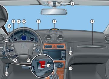
For a full view illustration of the instrument cluster, see “Instrument cluster” (컄 page 24).
1 Reset button The instrument cluster is activated when you 앫 open a door 앫 switch on the ignition (컄 page 36) 앫 press the reset button 1
앫 switch on the exterior lamps You can change the instrument cluster settings in the Instrument cluster submenu of the control system (컄 page 155).140
Warning!
No messages will be displayed if either the instrument cluster or the multifunction display is inoperative.
As a result, you will not be able to see infor- mation about your driving conditions, such as speed or outside temperature, warn- ing/indicator lamps, malfunction/warning messages or the failure of any systems. Driving characteristics may be impaired.
If you must continue to drive, please do so with added caution. Visit an authorized Mercedes-Benz Center as soon as possible.
Instrument cluster illumination
Use the reset button 1 to adjust the illumination brightness for the instrument cluster.
The instrument cluster illumination is dimmed or brightened automatically to suit ambient light conditions. The instrument cluster illumination will also be adjusted automatically when you switch on the vehicle’s exterior lamps.
To brighten illumination 왘 Turn reset button 1 clockwise.
The instrument cluster illumination will brighten.
To dim illumination 왘 Turn reset button 1 counterclock-
wise. The instrument cluster illumination will dim.
Coolant temperature indicator
The coolant temperature indicator is on the right side in the instrument cluster (컄 page 24).
Warning!
앫 Driving when your engine is overheated can cause some fluids which may have leaked into the engine compartment to catch fire. You could be seriously burned.
앫 Steam from an overheated engine can cause serious burns which can occur just by opening the hood. Stay away from the engine if you see or hear steam coming from it.
Stop the vehicle in a safe location away from other traffic. Turn off the engine, get out of the vehicle and do not stand near the vehicle until the engine has cooled down.
Excessive coolant temperature triggers a warning in the multifunction display (컄 page 385) and the red coolant warn- ing lamp in the instrument cluster comes on (컄 page 364). The engine should not be operated with the coolant temperature above 248°F (120°C). Doing so may cause serious engine damage which is not covered by the Mercedes-Benz Limited Warranty.
During severe operating conditions, e.g. stop-and-go traffic, the coolant temperature may rise close to 248°F (120°C).
Controls in detail Instrument cluster
Trip odometer
왘 Make sure you are viewing the stan- dard display in the multifunction dis- play (컄 page 148).
왘 If it is not displayed, press button è or ÿ on the multifunction steering wheel repeatedly until the standard dis- play appears (컄 page 144).
왘 Press and hold the reset button on the instrument cluster (컄 page 140) until the trip odometer is reset.
141
Controls in detail Instrument cluster
Tachometer
Outside temperature indicator
Warning!
The outside temperature indicator is not de- signed to serve as an ice-warning device and is therefore unsuitable for that purpose.
Indicated temperatures just above the freez- ing point do not guarantee that the road sur- face is free of ice. The road may still be icy, especially in wooded areas or on bridges.
The outside temperature is indicated in the multifunction display (컄 page 144).
The red marking on the tachometer (컄 page 24) denotes excessive engine speed.
Avoid driving at excessive engine speeds, as it may result in serious engine damage that is not covered by the Mercedes-Benz Limited Warranty.
To help protect the engine, the fuel supply is interrupted if the engine is operated within the red marking.
Clock
In vehicles with Audio 20, the clock can be set via the control system (컄 page 157).
Vehicles with COMAND*: For information on setting the time in COMAND, refer to the separate COMAND operating instructions.
142
The temperature sensor is located in the front bumper area. Due to its location, the sensor can be affected by road or engine heat during idling or slow driving. This means that the accuracy of the displayed temperature can only be verified by com- parison to a thermometer placed next to the sensor, not by comparison to external displays (e.g. bank signs etc.). When moving the vehicle into colder ambi- ent temperatures (e.g. when leaving your garage), you will notice a delay before the lower temperature is displayed. A delay also occurs when ambient temper- atures rise. This prevents inaccurate tem- perature indications caused by heat radiated from the engine during idling or slow driving.
i The displays for the audio systems (ra- dio, CD player etc.) will appear in En- glish, regardless of the language selected.
왔 Control system The control system is activated as soon as the SmartKey in the starter switch is turned to position 1 or as soon as the KEYLESS-GO* start/stop button is in position 1. The control system enables you to 앫 call up information about your vehicle 앫 change vehicle settings For example, you can use the control sys- tem to find out when your vehicle is next due for service, to set the language for messages in the instrument cluster dis- play, and much more.
Controls in detail Control system
Warning!
A driver’s attention to the road and traffic conditions must always be his/her primary focus when driving.
For your safety and the safety of others, selecting features through the multifunction steering wheel should only be done by the driver when traffic and road conditions permit it to be done safely.
Bear in mind that at a speed of just 30 mph (approximately 50 km/h), your vehicle is covering a distance of 44 feet (approxi- mately 14 m) every second.
The control system relays information to the multifunction display.
143
Controls in detail Control system
Multifunction display
Multifunction steering wheel
The displays in the multifunction display and the settings in the control system are controlled by the buttons on the multifunc- tion steering wheel (컄 page 26).
1 Outside temperature 2 Trip odometer 3 Current shift program mode 4 Main odometer 5 Current gear selector lever posi-
tion/gear range
For more information on menus displayed in the multifunction display, see “Menus” (컄 page 146).
144
1 Multifunction display
Operating the control system
2 Selecting the submenu or setting the
volume: Press button æ up / to increase ç down / to decrease
3 Telephone*: Press button s to take a call t to end a call
4 Menu systems:
Press button è for next menu ÿ for previous menu
5 Moving within a menu:
Press button j for next display k for previous display
Controls in detail Control system
Depending on the selected menu (컄 page 146), pressing the buttons on the multifunction steering wheel will alter what is shown in the multifunction display. The information available in the multifunc- tion display is arranged in menus, each containing a number of functions or sub- menus. The individual functions are then found within the relevant menu (radio or CD op- erations under Audio, for example). These functions serve to call up relevant informa- tion or to customize the settings for your vehicle.
It is helpful to think of the menus, and the functions within each menu, as being arranged in a circular pattern. 앫 If you press button è or ÿ
repeatedly, you will pass through each menu one after the other.
앫 If you press button k or j
repeatedly, you will pass through each function display, one after the other, in the current menu.
In the Settings menu, instead of functions you will find a number of submenus for calling up and changing settings. For instructions on using these submenus, see “Submenus in the Settings menu” (컄 page 153). The number of menus available in the sys- tem depends on which optional equipment is installed in your vehicle. The menus are described on the following pages.
145
Controls in detail Control system
Menus
This is what you will see when you scroll through the menus.
The table on the next page provides an overview of the individual menus.
146
Controls in detail Control system
Menus, submenus and functions
Menu 1
Standard display (컄 page 148) Run Flat Indicator*Menu 2
AUDIOMenu 3
NAV*(컄 page 149) Select radio station
(컄 page 150) Show route guid- ance instruc- tions, current direction traveled
Menu 4
Vehicle status message memory1
(컄 page 151) Calling up vehicle malfunction, warning and system status mes- sages stored in memoryMenu 5
SettingsMenu 6
Trip computerMenu 7
Telephone*(컄 page 152) Reset to factory settings
(컄 page 165) Fuel consumption statistics after start
(컄 page 167) Load phone book
Select satellite radio station* (USA only) Operate CD player
Digital speed- ometer
Call up mainte- nance service display Check engine oil level (CLK 500 only)
1 The vehicle status message memory menu is only displayed if there is a message stored.
Fuel consumption statistics since the last reset Call up range
Search for name in phone book
Instrument clus- ter submenu
Time/Date sub- menu
Lighting submenu
Vehicle submenu Convenience submenu
147
Controls in detail Control system
The headings used in the menus table are designed to facilitate navigation within the system and are not neces- sarily identical to those shown in the control system displays. The first function displayed in each menu will automatically show you which part of the system you are in.
Standard display menu
In the standard display, the outside tem- perature and the trip odometer are shown in the multifunction display.
You can have the digital speedometer displayed instead of the outside tem- perature in the standard display. You can select the setting in the submenu Instr. cluster via the function Basic display (컄 page 156).
148
Display digital speedometer 왘 Press button j or k until the digital speedometer appears in the multifunction display. The current vehicle speed is shown in the multifunction display and the sta- tus line appears.
1 Digital Speedometer 2 Status line with outside temperature 3 Trip odometer
You can have the digital speedometer displayed instead of the outside tem- perature in the status line. You can se- lect the setting in the submenu Instr. cluster via the function Status line display (컄 page 156).
1 Outside temperature 2 Trip odometer If you see another display, press button è or ÿ repeatedly until the standard display appears. 왘 Press button k or jto select the functions in the standard display menu.
The following functions are available:
Page Function 329
Run Flat Indicator* Call up digital speedometer 148
Call up maintenance service 349
display Check engine oil level (CLK 500 only)310
AUDIO menu
The functions in the Audio menu operate the audio equipment which you currently have turned on. If no audio equipment is currently turned on, the message Audio off is shown in the multifunction display. The following functions are available:
Function Select radio station Select satellite radio station* (USA only) Operate CD player
Page 149
149150
Select radio station 왘 Turn on the radio (컄 page 212) and se-
lect radio. Vehicles with COMAND*: Refer to separate operating instruc- tions.
왘 Press button è or ÿ repeatedly
until the currently tuned station appears in the multifunction display.
1 Waveband setting 2 Station frequency 왘 Press button k or j repeatedly
until the desired station is found.
You can only store new stations using the corresponding feature on the radio (컄 page 218). Vehicles with COMAND*: Refer to separate operating instructions. You can also operate the radio in the usual manner.
Controls in detail Control system
Select satellite radio station* (USA only) The satellite radio is treated as a radio application. 왘 Select satellite radio with the
corresponding soft key (SAT) in the radio menu.
1 SAT mode and preset number 2 Setting for station selection using
memory
3 Channel name or number 왘 Press button k or j repeatedly
until the desired channel is found.
149
Controls in detail Control system
For more information on satellite radio operation, see “Introduction to satellite radio* (USA only)” (컄 page 220). Vehicles with COMAND*: Refer to separate operating instructions.
Operate the CD player 왘 Turn on the radio and select CD or
CD changer* (컄 page 228). Vehicles with COMAND*: Refer to separate operating instructions.
왘 Press button è or ÿ repeatedly until the settings for the CD currently being played appear in the multifunc- tion display.
150
NAV* menu
The Nav menu contains the functions needed to operate your navigation system. 왘 Press button è or ÿ repeatedly until the message Nav appears in the multifunction display.
앫 If COMAND* is switched off, the mes- sage Nav off appears in the multifunc- tion display.
앫 With COMAND* switched on but route guidance not activated, the direction of travel and, if available, the name of the street currently traveld on appear in the multifunction display.
앫 With COMAND* switched on and route
guidance activated, the direction of travel and maneuver instructions ap- pear in the multifunction display.
Please refer to the COMAND* manual for instructions on how to activate the route guidance system*.
1 Current CD (with additional number
from 1 to 6 when running from CD changer*) 2 Current track 왘 Press button k or j repeatedly
until the desired track is selected.
To select a CD from the CD changer* magazine, press a number on the audio system or the COMAND* system key pad located in the center dashboard.
For more information on CD operation, see “CD mode” (컄 page 225) and for the CD changer*, see “CD changer*” (컄 page 228).
Vehicle status message memory menu
Use the vehicle status message memory menu to scan malfunction and warning messages that may be stored in the system. Such messages appear in the multifunction display and are based on conditions or system status the vehicle’s system recorded. The vehicle status message memory menu only appears if there are any messages stored.
Warning!
Malfunction and warning messages are only indicated for certain systems and are inten- tionally not very detailed. The malfunction and warning messages are simply a remind- er with respect to the operation of certain systems and do not replace the owner’s and/or driver’s responsibility to maintain the vehicle’s operating safety by having all required maintenance and safety checks performed on the vehicle and by bringing the vehicle to an authorized Mercedes-Benz Center to address the malfunction and warning messages (컄 page 370).
왘 Press button è or ÿ repeatedly
until the vehicle status message memory appears in the multifunction display. If the vehicle status message memory menu does not appear, then there are no messages stored.
Controls in detail Control system
Vehicle status messages have been recorded If conditions have occurred causing status messages to be recorded, the number of messages appears in the multifunction display:
1 Number of messages 왘 Press button k or j.
The stored messages will now be displayed in the order in which they have occurred. For malfunction and warning messag- es, see “Vehicle status messages in the multifunction display” (컄 page 370).
151
Controls in detail Control system
Should the vehicle’s system record any conditions while driving, the number of messages will reappear in the multifunc- tion display when the SmartKey in the starter switch is turned to position 0 or removed from the starter switch. With KEYLESS-GO*, turn off the engine by pressing the KEYLESS-GO* start/stop button and open the driver’s door.
The vehicle status message memory will be cleared when you switch on the ignition (컄 page 36). You will then only see high-priority messages in the multi- function display (컄 page 370).
Settings menu
In the Settings menu there are two functions: 앫 The function Reset to factory
settings?, with which you can reset all the settings to the original factory settings.
앫 A collection of submenus with which you can make individual settings for your vehicle.
왘 Press button è or ÿ repeatedly until the Settings menu appears in the multifunction display.
Resetting all settings You can reset all the functions of all submenus to the factory settings. 왘 Press the reset button in the
instrument cluster (컄 page 140) for approximately three seconds. The request to press the reset button once more to confirm appears in the multifunction display.
왘 Press the reset button once more.
The functions of all the submenus will reset to factory settings.
152
i The settings you have changed will not be reset unless you confirm the action by pressing the reset button a second time. After approximately five seconds, the Settings... menu reappears in the multifunction display. For safety reasons, the following function is not reset while driving: 앫 the Lamp circuit headlamp func-
tion in the Lighting submenu.
Submenus in the Settings menu 왘 Press button j.
The collection of the submenus appears in the multifunction display.
왘 Press button ç.
The selection marker moves to the next submenu.
The submenus are arranged by hierarchy. Scroll down with button ç, scroll up with button æ. With the selection marker on the desired submenu, use button j to access the individual functions within that submenu. Once within the submenu, you can use button j to move to the next function or button k to move to the previous function within that submenu.
Controls in detail Control system
The settings themselves are made with button æ or ç.
Resetting the functions of a submenu For each submenu you can reset all the functions to the factory settings. 왘 Move to a function in the submenu. 왘 Press the reset button (컄 page 140) in
the instrument cluster for approxi- mately three seconds. The request to press the reset button once more to confirm appears in the multifunction display.
왘 Press the reset button once more.
All functions of the submenu will reset to factory settings.
The settings you have changed will not be reset unless you confirm the action by pressing the reset button a second time. After approximately five seconds, the Settings menu reappears in the multifunction display.
153
Controls in detail Control system
The table below shows what settings can be changed within the various menus.
Detailed instructions on making individual settings can be found on the following pages.
INSTRUMENT CLUSTER TIME/Date Selecting speedometer display mode Selecting language
Setting time (hours)
Setting time (minutes)
LIGHTING Setting daytime running lamp mode (USA only) Setting locator lighting
VEHICLE Setting automatic lock- ing
CONVENIENCE Activate easy-entry/exit feature Setting parking position for exterior rear view mirror
Selecting display (speed display or outside temperature) for status indicator Selecting display (speed display or outside tem- perature) for standard display
Setting the date (month) Exterior lamps delayed
shut-off
Setting the date (day)
Interior lighting delayed shut-off
Setting the date (year)
154
Instrument cluster submenu Access the Instr. cluster submenu via the Settings menu. Use the Instr. clus- ter submenu to change the instrument cluster display settings. The following functions are available:
Function Selecting speedometer display mode Selecting language Selecting display (speed display or outside temperature) for status line Selecting display (speed display or outside temperature) for standard display
Page 155
155
156156
Controls in detail Control system
Selecting speedometer display mode 왘 Move the selection marker with
Selecting language 왘 Move the selection marker with
button æ or ç to the Instr. cluster submenu.
button æ or ç to the Instr. cluster submenu.
왘 Press button j or k repeatedly
until the message Display unit Speed-/odometer appears in the multifunction display. The selection marker is on the current setting.
왘 Press button j or k repeatedly until the message Language appears in the multifunction display. The selection marker is on the current setting.
왘 Press button æ or ç to set speedometer unit to km or miles.
컄컄
155
Controls in detail Control system
컄컄
왘 Press button æ or ç to select
the language to be used for the multifunction display messages. Available languages: 앫 German (Deutsch) 앫 English (English) 앫 French (francais) 앫 Italian (italiano) 앫 Spanish (Español) 앫 Dutch (Nederlands) 앫 Danish (Dansk) 앫 Swedish (Svenska) 앫 Portuguese (Português) 앫 Turkish (Türkçe)
156
Selecting display (speed display or out- side temperature) for status line 왘 Move the selection marker with
Selecting display (speed display or out- side temperature) for standard display 왘 Move the selection marker with
button æ or ç to the Instr. cluster submenu.
button æ or ç to the Instr. cluster submenu.
왘 Press button j or k repeatedly
왘 Press button j or k repeatedly
until the message Status line dis- play appears in the multifunction display. The selection marker is on the current setting.
until the message Basic display appears in the multifunction display. The selection marker is on the current setting.
왘 Press button æ or ç to select the display mode shown in the basic display.
왘 Press button æ or ç to select
the desired setting.
You will see the status line when you have called up a different display from the standard display.
Time/Date submenu Access the Time/Date submenu via the Settings menu. Use the Time/Date submenu to change the instrument cluster display settings. The following functions are available:
Function Setting the time (hours) Setting the time (minutes) Setting the date (month) Setting the date (day) Setting the date (year)
Page 157
158
158
159
159The Time/Date submenu is not shown in vehicles with COMAND*.
Setting time (hours) This function can only be seen in vehicles with audio system.
Vehicles with COMAND*: For information on setting the time in COMAND, refer to the separate COMAND operating instructions.
왘 Move the selection marker with
button æ or ç to the Time/Date submenu.
왘 Press button j or k repeatedly
until the message Clock, hours Confirm by press. R appears in the multifunction display. The selection marker is on the hour setting.
Controls in detail Control system
왘 Press button æ or ç to set the
hour.