- 2004 Mercedes-Benz CLK Class Cabriolet Owners Manuals
- Mercedes-Benz CLK Class Cabriolet Owners Manuals
- 2006 Mercedes-Benz CLK Class Cabriolet Owners Manuals
- Mercedes-Benz CLK Class Cabriolet Owners Manuals
- 2001 Mercedes-Benz CLK Class Cabriolet Owners Manuals
- Mercedes-Benz CLK Class Cabriolet Owners Manuals
- 2005 Mercedes-Benz CLK Class Cabriolet Owners Manuals
- Mercedes-Benz CLK Class Cabriolet Owners Manuals
- 2002 Mercedes-Benz CLK Class Cabriolet Owners Manuals
- Mercedes-Benz CLK Class Cabriolet Owners Manuals
- 2007 Mercedes-Benz CLK Class Cabriolet Owners Manuals
- Mercedes-Benz CLK Class Cabriolet Owners Manuals
- 2003 Mercedes-Benz CLK Class Cabriolet Owners Manuals
- Mercedes-Benz CLK Class Cabriolet Owners Manuals
- 2000 Mercedes-Benz CLK Class Cabriolet Owners Manuals
- Mercedes-Benz CLK Class Cabriolet Owners Manuals
- Download PDF Manual
-
앫 the parking brake is engaged
(컄 page 49)
앫 the luggage cover is latched, see
“Latch luggage cover” (컄 page 245)
앫 the ski sack roller blind is closed, see
“Closing ski sack roller blind” (컄 page 246)
앫 the trunk lid is closed 앫 the ignition is switched on (컄 page 36)
Controls in detail Soft top
왘 Pull up on the soft top switch as indi-
cated by the arrow 1 until the soft top is completely lowered into its trunk storage compartment. During the opening procedure the mul- tifunction display shows the message Top in operation. If the opening procedure is finished, the multifunction display will briefly show the message Top open. If you continuously pull on the soft top switch, the windows will close. However, the windows can also be closed/opened later on, for more informa- tion see “Opening and closing the windows with the soft top switch” (컄 page 241), or see “Opening and closing the windows” (컄 page 239).
The soft top cannot be opened using the soft top switch when the roll bars have been released. The roll bars need to be lowered before the soft top can be operated again using the soft top switch. If the roll bars have released and the soft top is closed, contact an authorized Mercedes-Benz Center to have the roll bars lowered. Do not at- tempt to lower the roll bars manually with the soft top closed. Lowering the roll bars manually with the soft top closed may impair the function of the roll bars (컄 page 401). If the roll bars have released and the soft top is open, you can lower the roll bars manually (컄 page 402) or contact an authorized Mercedes-Benz Center to have the roll bars lowered.
247
Controls in detail Soft top
For safety reasons, the soft top cannot be opened while driving. Make sure the soft top is dry before you open it. Otherwise water may enter the trunk interior.
To prevent mildew, the soft top must be dry before lowering it into the storage compartment. Do not lower a frozen soft top until thawed and dry. Lowering a frozen soft top may result in damage not covered by the Mercedes-Benz Limited Warranty.
248
Warning!
Closing the soft top
Do not place anything on the soft top com- partment cover. The soft top compartment cover must never be used by any persons as a seat bench. Raising of the roll bars could result in seri- ous personal injury.
1 Soft top closing Before pressing the soft top switch, you must make sure: 앫 the parking brake is engaged
(컄 page 49)
앫 the trunk lid is closed 앫 the ignition is switched on (컄 page 36)
i The soft top cannot be closed using the soft top switch when the roll bars have been released. The roll bars need to be lowered before the soft top can be op- erated again using the soft top switch. If the roll bars have released and the soft top is open, you can lower the roll bars manually (컄 page 402) or contact an authorized Mercedes-Benz Center to have the roll bars lowered.
Controls in detail Soft top
Warning!
To prevent possible accidents, drive the ve- hicle only with the soft top either completely closed and locked, or fully lowered into its storage compartment.
If the soft top does not completely open or close, a warning sounds. In the multifunc- tion display you will see K, and the mes- sage Top being lowered! appears. After about 15 seconds the roof hydraulics lose pressure. Properly lock the soft top (컄 page 250) be- fore continuing to drive.
왘 Press the soft top switch as indicated
by the arrow 1 until the soft top is completely closed and locked. During the closing procedure the multi- function display shows the message Top in operation. If the soft top is closed and locked, the multifunction display will briefly show the message Top closed. If you continuously press on the soft top switch the windows will close.
However, the windows can also be closed/opened later on, for more informa- tion see “Opening and closing the windows with the soft top switch” (컄 page 241) or see “Opening and closing the windows” (컄 page 239).
For safety reasons, the soft top cannot be opened while driving.
249
Controls in detail Soft top
Locking the soft top after raising/low- ering
Warning!
The soft top is not fully closed and locked or not fully opened if: 앫 the message Top in operation! is
shown in the multifunction display
앫 a warning sounds for 10 seconds and
the message Lock top is shown in the multifunction display when starting to drive
To prevent possible accidents, drive the ve- hicle only with the soft top either completely closed and locked, or fully lowered into its storage compartment.
If the soft top is not properly locked, lock it as described below.
250
Unlocked status noticed when stopped 왘 Switch on the ignition (컄 page 36). 왘 To lock the soft top in its fully closed
position, press soft top switch. The message Top closed will be shown in the multifunction display.
or: 왘 To lock the soft top in its fully opened position, pull up on the soft top switch. The message Top open will be shown in the multifunction display.
Unlocked status noticed while driving
Warning!
Stop the vehicle and lock the soft top before continuing to drive. You could otherwise en- danger yourself and others.
왘 Stop the vehicle. 왘 Leave the ignition switched on. 왘 To lock the soft top in its fully closed
position, press soft top switch. The message Top closed will be shown in the multifunction display.
or: 왘 To lock the soft top in its fully opened position, pull up on the soft top switch. The message Top open will be shown in the multifunction display.
Warning!
If the soft top does not completely open or close, the roof hydraulics will lose pressure and the soft top is lowered 앫 after approximately seven minutes
when the ignition is switched on.
앫 after approximately 15 seconds when
the ignition is switched off.
Shortly before the soft top is lowered, a warning will sound. In the multifunction dis- play you will see K, and the message Top being lowered! appears. 앫 Properly lock the soft top (컄 page 250)
before continuing to drive.
Opening and closing the soft top with the SmartKey The windows will also be opened or closed when you operate the soft top with the SmartKey.
Warning!
Before operating the soft top, make sure no persons can be injured by the moving parts (roll bar, soft top frame, and soft top com- partment cover) due to negligence.
Hands must never be placed near the roll bar, soft top frame, upper windshield area, shelf behind roll bar, or soft top storage compartment while the soft top is being raised or lowered. Serious personal injury may occur.
If potential danger exists, release the re- spective button on the SmartKey. This im- mediately interrupts the raising or lowering procedure. You then can operate Œ to lower or ‹ to raise the soft top away from the danger zone.
Controls in detail Soft top
왘 Aim the transmitter eye at the driver’s
door handle.
251
Controls in detail Soft top
Opening (Summer opening feature) 왘 Press and hold button Œ until the
Closing (Convenience feature) 왘 Press and hold button ‹ until the
Warning!
soft top is completely open. The windows and soft top begin to open after approximately one second. During the opening procedure the mul- tifunction display shows the message Top in operation. If the opening procedure is finished, the multifunction display will briefly show the message Top open.
soft top is completely closed. The windows and soft top begin to close after approximately one second. During the closing procedure the multi- function display shows the message Top in operation. If the soft top is closed and locked, the multifunction display will briefly show the message Top closed.
왘 Release transmit button Œ to inter-
왘 Release transmit button ‹ to inter-
rupt procedure.
rupt procedure.
Make sure all side windows and the soft top are properly closed before leaving the vehicle.
If the soft top does not completely open or close, a warning sounds and the soft top switch flashes. In the multifunction display you will see K, and the message Top being lowered! appears. After about 15 seconds the roof hydraulics lose pres- sure. Properly lock the soft top (컄 page 250) be- fore continuing to drive.
252
Controls in detail Soft top
Wind screen
Warning!
Installing 왘 Remove the wind screen from its stor-
age bag.
The wind screen can restrict the driver’s vi- sion to the rear of the vehicle. To prevent a possible accident when visibility is limited (e.g. in darkness), the upper part of the wind screen should be folded back.
The wind screen deflects drafts away from the driver and passenger when the soft top is lowered. It is stored in a separate stor- age bag in the trunk.
1 Upper section 2 Lower section 왘 Fold sections 1 and 2 together.
3 Catch 4 Retainer claw 5 Snap fastener 왘 Press retainer claw 4 on upper sec-
tion into snap fastener 5 of lower sec- tion.
컄컄
253
Controls in detail Soft top
컄컄
6 Retaining lugs 7 Mounting fixture on right side 8 Catch 왘 Fold retaining lugs 6 out. 왘 Slide pre-assembled wind screen into mounting fixture on right side 7 using retaining pin on right side. Simulta- neously, retaining lugs 6 should slide into seat belt passage in rear bench seat.
254
왘 Pull catch 8 back and guide left re-
taining pin into mounting fixture on left side.
왘 Fold upper section of wind screen up toward head restraints until it stops.
Warning!
Check for secure locking by pulling up on the wind screen.
To prevent personal injury, remove wind screen if rear seats are to be occupied by passengers.
Removing 왘 Fold upper section of wind screen back
down.
왘 Pull catch 8 back and pull wind
screen out toward front of vehicle. Be careful not to damage interior trim with guide tabs.
왘 Fold retaining lugs 6 back.
9 Catch 왘 Press catch 9 and fold upper and low-
er sections back.
왘 Place the wind screen back into the
bag.
왔 Driving systems The driving systems of your vehicle are de- scribed on the following pages: 앫 Cruise control, with which the vehicle
can maintain a preset speed
앫 Parktronic*, which serves as a parking
assistant
For information on the BAS, ABS, and ESP driving systems, see “Driving safety sys- tems” (컄 page 84).
Cruise control
Cruise control automatically maintains the speed you set for your vehicle. Use of cruise control is recommended for driving at a constant speed for extended periods of time. CLK 320/CLK 55 AMG: You can set or resume cruise control at any speed over 20 mph (30 km/h). CLK 500: You can set or resume cruise control at any speed over 25 mph (40 km/h). The cruise control function is operated by means of the cruise control lever. The cruise control lever is the uppermost lever on the left-hand side of the steering column (컄 page 22).
Controls in detail Driving systems
Warning!
Cruise control is a convenience system de- signed to assist the driver during vehicle op- eration. The driver is and must remain at all times responsible for the vehicle speed and for safe brake operation.
Only use cruise control if the road, traffic and weather conditions make it advisable to travel at a steady speed. 앫 The use of cruise control can be danger- ous on winding roads or in heavy traffic because conditions do not allow safe driving at a steady speed.
앫 The use of cruise control can be danger- ous on slippery roads. Rapid changes in tire traction can result in wheel spin and loss of control.
앫 Deactivate cruise control when driving
in fog.
The “Resume” function should only be oper- ated if the driver is fully aware of the previ- ously set speed and wishes to resume this particular preset speed.
255
Controls in detail Driving systems
1 Set current or higher speed 2 Set current or lower speed 3 Cancel cruise control 4 Resume to last set speed
256
Warning!
CLK 500:
Setting current speed 왘 Accelerate or decelerate to the desired
speed.
Cruise control brakes automatically so that the set speed is not exceeded. The brake pedal is depressed automatically to do this.
Keep in mind that cruise control is a conve- nience system designed to assist the driver during vehicle operation. The driver is and must always remain responsible for the ve- hicle’s speed and for safe brake operation.
Keep driver’s foot area clear at all times, in- cluding the area under the brake pedal. Ob- jects stored in this area may impair pedal movement which could interfere with the braking ability of the cruise control system.
Do not place your foot under the brake pedal - your foot could become caught.
왘 Briefly lift 1 or depress 2 the cruise
control lever (컄 page 256). The current speed is set.
왘 Remove your foot from the accelerator
pedal. Cruise control is activated.
The selected speed appears in the multi- function display for approximately five sec- onds, and the corresponding speedometer segments from the selected speed to the vehicle maximum speed are illuminated.
i On uphill or downhill grades, cruise control may not be able to maintain the set speed. Once the grade eases, the set speed will be resumed. CLK 320/CLK 55 AMG: If the engine’s braking power does not brake the vehicle sufficiently on down- hill grades, the automatic transmission will automatically downshift. CLK 500: On downhill grades, the cruise control will hold the set speed with active brak- ing action. In addition, on longer downhill grades the automatic transmission will auto- matically downshift.
Canceling cruise control There are several ways to cancel cruise control: 왘 Step on the brake pedal.
Cruise control is canceled. The last speed set is stored for later use.
or 왘 Briefly push the cruise control lever to
position 3. Cruise control is canceled. The last speed set is stored for later use.
The last stored speed is canceled when you turn off the engine.
Controls in detail Driving systems
The cruise control switches off auto- matically, if CLK 320/CLK 55 AMG: 앫 you step on the brake pedal. 앫 you move the gear selector lever to
position N while driving.
앫 the vehicle speed is below 20 mph
(30 km/h).
앫 ESP is in operation. The segments in the multifunction dis- play are flashing. CLK 500: 앫 you step on the brake pedal. 앫 you press the parking brake pedal.
In this case the segments in the multifunction display (컄 page 256) go out and no warning sounds.
257
Controls in detail Driving systems
앫 the vehicle speed is below 25 mph
(40 km/h).
앫 ESP is in operation or switched off
with the ESP switch (컄 page 87).
앫 you move the gear selector lever to
position N while driving.
The segments in the multifunction dis- play (컄 page 256) go out, and an acoustic warning sounds.
Moving gear selector lever to position N while driving also cancels cruise control. However, the gear se- lector lever should not be moved to position N while driving except to coast when the vehicle is in danger of skid- ding (e.g. on icy roads).
258
Depressing the accelerator pedal does not deactivate cruise control. After brief acceleration (e.g. for passing), cruise control will resume the last speed set.
Setting a higher speed 왘 Lift the cruise control lever in direction of arrow 1 (컄 page 256) and hold it up until the desired speed is reached.
왘 Release the cruise control lever.
The new speed is set.
Setting a lower speed 왘 Depress the cruise control lever in
direction of arrow 2 (컄 page 256) and hold it down until the desired speed is reached.
왘 Release the cruise control lever.
The new speed is set.
CLK 320/CLK 55 AMG When you use the cruise control lever to decelerate, the transmission will automatically downshift if the engine’s braking power does not brake the vehicle sufficiently. CLK 500: When you use the cruise control lever to decelerate, the brake system will automatically brake the vehicle if the engine’s braking power does not brake the vehicle sufficiently.
Fine adjustment in 1 mph (Canada: 1 km/h) increments
Setting to last stored speed (“Resume” function)
Faster 왘 Briefly tip the cruise control lever in di-
rection of arrow 1 (컄 page 256).
Slower 왘 Briefly tip the cruise control lever in di-
rection of arrow 2 (컄 page 256).
Warning!
The speed stored in memory should only be set again if prevailing road conditions per- mit. Possible acceleration or deceleration differences arising from returning to the pre- set speed could cause an accident and/or serious injury to you and others.
왘 Briefly push cruise control lever to
position 4 (컄 page 256). The cruise control resumes the last set speed.
왘 Remove your foot from the accelerator
pedal.
Controls in detail Driving systems
The selected speed appears in the multi- function display for approximately five sec- onds, and the corresponding speedometer segments from the selected speed to the vehicle maximum speed are illuminated.
259
Controls in detail Driving systems
Parktronic system (Parking assist)*
Warning!
Parktronic is a supplemental system. It is not intended to, nor does it replace, the need for extreme care. The responsibility during parking and other critical maneuvers always rests with the driver.
Special attention must be paid to objects with smooth surfaces or low silhouettes (e.g. trailer couplings, painted posts or road curbs). Such objects may not be detected by the system and can damage the vehicle.
The operational function of the Parktronic system can be affected by dirty sensors, es- pecially at times of snow and ice, see “Cleaning the Parktronic system* sensors” (컄 page 349). Interference caused by other ultrasonic sig- nals (e.g. working jackhammers, car wash, or the air brakes of trucks) can cause the system to send erratic indications, and should be taken into consideration.
260
Warning!
Make sure no persons or animals are in the area in which you are maneuvering. You could otherwise injure them.
The Parktronic system is an electronic aid designed to assist the driver during park- ing maneuvers. It visually and audibly indi- cates the relative distance between the vehicle and an obstacle. The Parktronic system is automatically ac- tivated when you switch on the ignition and placed the gear selector lever in position D, R, or N. The Parktronic system deactivates at speeds over approximately 11 mph (18 km/h). At lower speeds the Parktronic system turns on again. The Parktronic system also deactivates when you place the gear selector lever in position P.
The Parktronic system monitors the sur- roundings of your vehicle with six sensors in the front bumper and four sensors in the rear bumper.
1 Sensors in the front bumper
Range of the sensors To function properly, the sensors must be free of dirt, ice, snow and slush. Clean the sensors regularly, being careful not to scratch or damage the sensors, see “Cleaning the Parktronic system* sensors” (컄 page 349).
Controls in detail Driving systems
Front sensors
Minimum distance
Center Corners
approx. 40 in (100 cm) approx. 24 in (60 cm)
Center Corners
approx. 8 in (20 cm) approx. 6 in (15 cm)
If the system detects an obstacle in this range, all the distance warning segments illuminate and you hear a warning signal. If the obstacle is closer than the minimum distance, the actual distance may no long- er be indicated by the system.
Rear sensors
Center Corners
approx. 48 in (120 cm) approx. 32 in (80 cm)
During parking maneuvers, pay special attention to objects located above or below the height of the sensors (e.g. planters or trailer hitches). The Parktronic system will not detect such objects at close range and damage to your vehicle or the object may result. Ultrasonic signals from outside sourc- es (e.g. truck air brakes, car wash, or jackhammers) may impair the opera- tion of the Parktronic system.
261
Controls in detail Driving systems
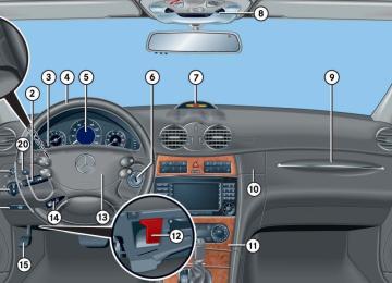
Warning indicators Visual signals indicate to the driver the rel- ative distance between the sensors and an obstacle. The warning indicator for the front area is located above the center air vents in the dashboard. The warning indi- cator for the rear area is integrated be- tween the rear backrests.
The position of the gear selector lever de- termines which warning indicators will be activated.
Gear selector le- ver position R or N
Warning indicator
Front area activated Front and rear area activated Neither activated
1 Left side of the vehicle 2 Right side of the vehicle Each warning indicator is divided into six yellow and two red distance segments for either side of the vehicle. The Parktronic system is ready when the border around the indicator is illuminated.
262
As your vehicle approaches an object, one or more distance segments will illuminate, depending on the distance. When the eighth distance segment illuminates, you have reached the minimum distance. 앫 Front area: An intermittent acoustic
warning will sound as the first red dis- tance segment illuminates and a con- stant acoustic warning lasting a maximum of two seconds will sound for the second red distance segment. The signal is canceled when the gear selec- tor lever is placed in position P.
앫 Rear area: An intermittent acoustic
warning will sound as the first red dis- tance segment illuminates and a con- stant acoustic warning lasting a maximum of two seconds will sound for the second red distance segment. The signal is canceled when the gear selec- tor lever is placed in position D or P.
Controls in detail Driving systems
If only the red distance segments illumi- nate and no acoustic warning sounds, the Parktronic system sensors are dirty or there is an interference from other radio or ultrasonic signals. The Parktronic system will automatically switch off after 20 sec- onds and the indicator lamp in the Park- tronic switch comes on. 왘 Switch off the ignition. 왘 Clean the Parktronic system sensors
(컄 page 349).
왘 Switch on the ignition. or 왘 Check the Parktronic system operation at another location to rule out interfer- ence from outside radio or ultrasonic signals.
Switching on the Parktronic system 왘 Press Parktronic switch 1 again.
Indicator lamp 2 goes out.
The Parktronic system is automatically switched on when the ignition is switched on (컄 page 36).
Parktronic system malfunction If only the red distance segments illumi- nate and an acoustic warning sounds, there is a malfunction in the Parktronic system. The Parktronic system will auto- matically switch off after 20 seconds and the indicator lamp in the Parktronic switch comes on. 왘 Have the Parktronic system checked
by an authorized Mercedes-Benz Center as soon as possible.
Switching the Parktronic system on/off The Parktronic system can be switched off manually. The Parktronic switch is located in the up- per part of the center console (컄 page 27).
1 Parktronic switch 2 Indicator lamp
Switching off the Parktronic system 왘 Press Parktronic switch 1. Indicator lamp 2 comes on.
263
Controls in detail Loading
Ski sack*
Unfolding and loading 왘 Close soft top completely
(컄 page 248). 왘 Open trunk lid.
1 Left hinge 2 Right hinge 3 Pull strap 왘 Pull ski sack roller blind upward using
pull strap 3.
왘 Manually fold left 1 and right
hinges 2 of ski sack roller blind all the way up.
4 Handle 5 Cover 6 Armrest 왘 Fold armrest 6 down (arrow). 왘 Pull handle 4 and swing cover 5
down.
왘 Fold luggage cover back in direction of
the arrow.
264
7 Hook and loop fastener 왘 Unfasten hook and loop fastener 7. 왘 Pull ski sack into passenger compart-
ment and unfold.
8 Flap 9 Catch 왘 Pull down catch 9. 왘 Open the flap 8 downwards in the di-
rection of the arrow.
Controls in detail Loading
왘 From trunk, slide skis into ski sack.
Warning!
The ski sack is designed for up to two pairs of skis. Do not load the ski sack with other objects.
Always fasten the ski sack securely. In an accident, an unfastened ski sack can cause injury to vehicle occupants.
컄컄
265
Controls in detail Loading
컄컄
a Strap 왘 Tighten strap a by pulling at the loose end (arrow) until the skis in the ski sack are tightly secured.
b Hook c Eye 왘 Connect hook b to eye c located on
center tunnel in front of rear seat bench.
왘 Tighten strap by pulling at the loose
end (arrow).
266
Unloading and folding 왘 Loosen both straps. 왘 Disconnect hook b from eye c. 왘 Unload skis. 왘 Close flap 8 in trunk. 왘 Fold and flatten ski sack lengthwise. 왘 Place folded ski sack inside recess of
backrest.
왘 Fasten hook and loop fastener.
왘 Close ski sack compartment cover.
Closing ski sack roller blind
왘 To snap ski sack roller blind into place,
press left and right hinges where the word PRESS can be seen.
왘 Fold luggage cover back and close it
securely (컄 page 245).
Removal of ski sack For removal of the ski sack we recommend that you contact an authorized Mercedes-Benz Center.
Controls in detail Loading
1 Left hinge 2 Right hinge 3 Pull strap 왘 Pull ski sack roller blind downward us-
ing pull strap 3.
왘 Manually fold left 1 and right
hinges 2 of ski sack roller blind all the way down.
Warning!
Never drive vehicle with trunk open while the ski sack is removed. Deadly carbon monoxide (CO) gases may enter vehicle in- terior, resulting in unconsciousness and death.
To prevent unauthorized persons from access to the trunk, always close the flap.
267
Controls in detail Loading
Loading instructions
The total load weight including vehicle oc- cupants and luggage/cargo should not ex- ceed the load limit or vehicle capacity weight indicated on the corresponding placard located on the driver’s door B-pil- lar. The handling characteristics of a fully load- ed vehicle depend greatly on the load dis- tribution. It is therefore recommended to load the heaviest items being placed to- wards the front of the vehicle. Always place items being carried against rear seat backrests, and fasten them as se- curely as possible. The heaviest portion of the cargo should al- ways be kept as low as possible since it in- fluences the handling characteristics of the vehicle.
268
To prevent damage to the soft top or luggage/cargo when lowering the roof: 앫 load trunk only to the height of the
luggage cover
앫 do not permit luggage/cargo to push up the closed luggage cover 앫 do not place anything on the shelf
behind the roll bar
앫 do not place anything on the soft
top compartment cover
Warning!
Always fasten items being carried as secure- ly as possible.
In an accident, during hard braking or sud- den maneuvers, loose items will be thrown around inside the vehicle and can cause in- jury to vehicle occupants unless the items are securely fastened in the vehicle.
To help avoid personal injury during a colli- sion or sudden maneuver, exercise care when transporting cargo. Put luggage or car- go in the trunk if possible.
Never drive vehicle with trunk open. Deadly carbon monoxide (CO) gases may enter ve- hicle interior resulting in unconsciousness and death.
왔 Useful features Storage compartments
Warning!
To help avoid personal injury during a colli- sion or sudden maneuver, exercise care when stowing objects in the vehicle. Put lug- gage or cargo in the trunk if possible. Do not pile luggage or cargo higher than the seat backs.
Luggage nets cannot secure hard or heavy objects.
Keep compartment lids closed. This will help to prevent stored objects from being thrown about and injuring vehicle occupants during an accident.
Make sure no objects fall into the open- ings of the subwoofer between the rear seats. If necessary, contact an authorized Mercedes-Benz Center to remove any objects which may have fallen into the openings.
Glove box
Controls in detail Useful features
Opening the glove box 왘 Pull lid release 2.
The glove box lid opens downward.
Closing the glove box 왘 Push lid up to close.
The glove box lid contains a compart- ment for eyeglasses. Close the compartment for glasses first before closing the glove box. Audio system/COMAND* with CD changer*: The CD changer* is located in the glove box.
1 Glove box 2 Glove box lid release
269
Controls in detail Useful features
Armrest storage compartments
1 Handle 2 Button (passenger side) 3 Button (driver side) 4 Compartment lock (lock position) 5 Compartment lock (unlock position)
Opening storage compartment 왘 Pull handle 1 and lift armrest.
Closing storage compartment 왘 Press armrest down until it engages
into place.
270
Opening telephone compartment 왘 Press button 3 on driver’s side or button 2 on passenger side and lift armrest.
Closing telephone compartment 왘 Press armrest down until it engages
into place.
Locking compartment 왘 Remove the mechanical key from the
SmartKey (컄 page 397).
왘 Turn the compartment lock to
position 5.
Unlocking compartment 왘 Turn the compartment lock to
position 4.
왘 Insert the mechanical key in the
SmartKey.
Changing inclination of armrest
1 Handle 왘 Pull up on armrest.
Lowering armrest 왘 Pull handle 1 to lower armrest.
Depending on production date, the changing inclination of armrest feature may not be available in your vehicle.
Storage box The storage box is in front of the armrest storage compartment.
Opening storage box 왘 Pull storage box 1 in the direction of
arrow.
Closing storage box 왘 Press storage box 1 back until it
engages into place.
Armrest in the rear passenger compartment
1 Storage box
Warning!
Do not use this storage compartment as an ashtray and/or place hot cigarettes or other hot smoking materials in the storage box. Placing such materials in the storage box may cause vehicle damage and/or poten- tially cause a vehicle fire.
왘 Pull the top of the armrest out and fold
it down.
Controls in detail Useful features
Cup holder in the dashboard
Warning!
In order to help prevent spilling liquids on vehicle occupants, only use containers that fit into the cup holder. Use lids on open containers and do not fill containers to a height where the contents, especially hot liquids, could spill during braking, vehicle maneuvers, or in an accident.
When not in use, keep the cup holder closed. An open cup holder may cause injury to you and others when contacted during braking, vehicle maneuvers, or in an accident.
Keep in mind that objects placed in cup holder may come loose during braking, vehicle maneuvers, or in an accident and be thrown around in the vehicle interior. Objects thrown around in the vehicle interior may cause an accident and/or serious personal injury.
271
Storage bags Storage bags are located on the rear side of the front seats.
Warning!
Do not place heavy or fragile objects, or ob- jects having sharp edges, in the storage bags.
In an accident, during hard braking or sud- den maneuvers, they could be thrown around inside the vehicle, and cause injury to vehicle occupants.
Parcel net in front passenger footwell A small convenience parcel net is located in the front passenger footwell. It is for small and light items, such as road maps, mail, etc.
Warning!
Do not place heavy or fragile objects, or ob- jects having sharp edges, in the parcel net.
In an accident, during hard braking or sud- den maneuvers, they could be thrown around inside the vehicle, and cause injury to vehicle occupants.
Controls in detail Useful features
1 Cover
Opening cup holder 왘 Push cover 1.
The cup holder opens automatically.
Closing cup holder 왘 Push the cup holder back until it
engages.
272
Controls in detail Useful features
Ashtrays
Removing ashtray insert
Center console ashtray
Warning!
Reinstalling the ashtray insert 왘 Push the ashtray insert 3 down into
the retainer until it engages.
Remove front ashtray only with vehicle standing still. Set the parking brake to se- cure vehicle from movement. Move gear se- lector lever to position N. With gear selector lever in position N, turn off the engine.
왘 Push down cover plate 1 to close
ashtray. The cover plate engages.
Rear seat ashtray
1 Cover plate 2 Sliding button 3 Ashtray insert
Opening ashtray 왘 Briefly press the bottom of cover
plate 1. The cover plate opens automatically.
왘 Secure vehicle from movement by
setting the parking brake.
왘 Move the gear selector lever to
position N. Now you have more room to take out the insert.
왘 Push sliding button 2 to the right.
The ashtray is disengaged and slides a short way in direction of arrow 3.
왘 Remove the ashtray insert.
1 Button 2 Ashtray insert 3 Cover
273
Controls in detail Useful features
Opening ashtray 왘 Pull at top of cover 3.
Removing ashtray insert 왘 Push button 1 to disengage ashtray
insert 2 and remove it.
Reinstalling ashtray insert 왘 Push the ashtray insert 2 down into
the retainer until it engages.
왘 Push at top of cover 3 to close
ashtray.
274
Cigarette lighter
1 Cover 2 Cigarette lighter 왘 Switch on the ignition (컄 page 36). 왘 Briefly press the bottom of cover
plate 1. The cover plate opens automatically.
왘 Push in cigarette lighter 2.
The cigarette lighter will pop out automatically when hot.
Warning!
Never touch the heating element or sides of the lighter; they are extremely hot. Hold the knob only.
When leaving the vehicle, always remove the SmartKey or SmartKey with KEYLESS-GO* from the starter switch, take it with you, and lock the vehicle. Do not leave children unat- tended in the vehicle, or with access to an unlocked vehicle. Unsupervised use of vehi- cle equipment may cause an accident and/or serious personal injury.
The lighter socket can be used to ac- commodate electrical accessories up to a maximum 85 W.
왘 Push down cover plate 1 to close
ashtray. The cover plate engages.
Electrical outlet in the rear passenger compartment
Floormats*
1 Electrical outlet 2 Cover 왘 Switch on the ignition (컄 page 36). 왘 Pull at top of cover 2. 왘 Flip cover 1 to the left and insert
electrical plug (cigarette lighter type).
The electrical outlet can be used to accommodate electrical consumers (e.g. air pump, auxiliary lamps) up to a maximum of 180 W.
Removing 왘 Pull floormats off of retainer pins 2 in
direction of arrow 1. 왘 Remove the floormats.
Installing 왘 Lay down the floormat. 왘 Press the floormat eyelets 4 onto re- tainer pins 5 in direction of arrow 3.
Controls in detail Useful features
Warning!
Whenever you are using floormats, make sure there is enough clearance and that the floormats are securely fastened.
Floormats should always be securely fas- tened using eyelets 4 and retainer pins 5. Before driving off, check that the floormats are securely in place and adjust them if nec- essary. A loose floormat could slip and hinder proper functioning of the pedals.
275
Controls in detail Useful features
Telephone*
Warning!
Never operate radio transmitters equipped with a built-in or attached antenna (i.e. with- out being connected to an external antenna) from inside the vehicle while the engine is running. Doing so could lead to a malfunc- tion of the vehicle’s electronic system, pos- sibly resulting in an accident and/or serious personal injury.
Radio transmitters, such as a portable tele- phone or a citizens band unit, should only be used inside the vehicle if they are con- nected to an antenna that is installed on the outside of the vehicle. The external antenna must be approved by Mercedes-Benz. Please contact an autho- rized Mercedes-Benz Center for informa- tion on the installation of an approved external antenna. Refer to the radio trans- mitter operation instructions regarding use of an external antenna.
276
Bear in mind that at a speed of just 30 mph (approximately 50 km/h), your vehicle is covering a distance of 44 feet (approximately 14 m) every second.
You can take and place telephone calls using the s and t buttons on the steering wheel. To carry out other tele- phone functions, use the control system (컄 page 160). See separate operating manual for instruc- tions on how to use the telephone.
Warning!
Please do not forget that your primary re- sponsibility is to drive the vehicle. A driver’s attention to the road must always be his/her primary focus when driving. For your safety and the safety of others, we rec- ommend that you pull over to a safe location and stop before placing or taking a tele- phone call. If you choose to use the telephone1 while driving, please use the hands-free device and only use the telephone when road, weather and traffic conditions permit. Some jurisdictions prohibit the driver from using a cellular telephone while driving a vehicle.
Only operate the audio system or CO- MAND* (Cockpit Management and Data System)1 if road, weather an traffic condi- tions permit.
1 Observe all legal requirements.
Tele Aid
The initial activation of the Tele Aid system may only be performed by completing the subscriber agreement and placing an acquaintance call using the ¡ button. Failure to complete either of these steps will result in a system that is not activated. If you have any questions regarding activation, please call the Response Center at 1-800-756-9018 (in the USA) or 1-888-923-8367 (in Canada).
The Tele Aid system (Telematic Alarm Identification on Demand) The Tele Aid system consists of three types of response: 앫 automatic and manual emergency 앫 roadside assistance and 앫 information
The Tele Aid system is operational provid- ing that the vehicle’s battery is charged, properly connected, not damaged and cellular and GPS coverage is available. The speaker volume of a Tele Aid call can be adjusted when using the volume control on the multifunction steering wheel. To raise, press button æ and to lower, press button ç. The volume can also be adjusted using the volume knob on your audio system or COMAND* head unit. 왘 To activate, press the SOS button, the
Roadside Assistance button • or the Information button ¡, depend- ing on the type of response required.
The SOS button is located above the interior rear view mirror. The Roadside Assistance button • and the Information button ¡ are located below the center armrest cover.
Controls in detail Useful features
Shortly after the completion of your Tele Aid acquaintance call, you will receive a user ID and password. By visiting www.mbusa.com and selecting “Tele Aid” (USA only), you will have access to account information, remote door unlock and more.
The Tele Aid system utilizes the cellular network for communication and the GPS (Global Positioning System) satel- lites for vehicle location. If either of these signals is unavailable, the Tele Aid system may not function and if this occurs, assistance must be sum- moned by other means.
System self-check Initially, after switching on the ignition, malfunctions are detected and indicated (the indicator lamps in the SOS button, the Roadside Assistance button • and the Information button ¡ stay on longer than ten seconds or do not come on). The
277
Controls in detail Useful features
message Tele Aid malfunction Drive to workshop appears in the multifunction dis- play.
Warning!
If the indicator lamps in the SOS button, in the Roadside Assistance button and/or in the Information button remain illuminated constantly in red and/or message Tele Aid malfunction Drive to workshop is displayed in the multifunction display after the system self-check, a mal- function in the system has been detected.
If a malfunction is indicated as outlined above, the system may not operate as expected. Have the system checked at the nearest Mercedes-Benz Center as soon as possible.
278
Emergency calls An emergency call is initiated automatically following an accident in which the emergency tensioning devices (ETDs) or air bags deploy. An emergency call can also be initiated manually by opening the cover next to the interior rear view mirror labeled SOS, then briefly pressing the button located under the cover. See (컄 page 279) for instructions on initiating an emergency call manually. Once the emergency call is in progress, the indicator lamp in the SOS button will begin to flash. The message Connecting call appears in the multifunction display and the audio system is muted. When the connection is established, the message Call connected appears in the multifunc- tion display. All information relevant to the emergency, such as the location of the vehicle (determined by the GPS satellite location system), vehicle model, identifica- tion number and color are generated.
A voice connection between the Response Center and the occupants of the vehicle will be established automatically soon af- ter the emergency call has been initiated. The Response Center will attempt to determine more precisely the nature of the emergency provided they can speak to an occupant of the vehicle. The Tele Aid system is available if: 앫 it has been activated and is
operational. Activation requires a subscription for monitoring services, connection and cellular air time
앫 the relevant cellular phone network
and GPS signals are available and pass the information on to the Response Center
Location of the vehicle on a map is only possible if the vehicle is able to receive signals from the GPS satellite network and pass the information on to the Response Center.
Warning!
If the indicator lamp in the SOS button is flashing continuously and there was no voice connection to the Response Center established, then the Tele Aid system could not initiate an emergency call (e.g. the rele- vant cellular phone network is not available). The message Call failed appears in the multifunction display for approximately ten seconds.
Should this occur, assistance must be summoned by other means.
Controls in detail Useful features
Initiating an emergency call manually
왘 Wait for a voice connection to the
Response Center.
왘 Close cover 1 after the emergency
call is concluded.
Warning!
If you feel at any way in jeopardy when in the vehicle (e.g. smoke or fire in the vehicle, vehicle in a dangerous road location), please do not wait for voice contact after you have pressed the emergency button. Carefully leave the vehicle and move to a safe loca- tion. The Response Center will automatically contact local emergency officials with the vehicle’s approximate location if they receive an automatic SOS signal and cannot make voice contact with the vehicle occupants.
279
1 Cover 2 SOS button 왘 Briefly press on cover 1.
The cover will open.
왘 Press SOS button 2 briefly.
The indicator lamp in SOS button 2 will flash until the emergency call is concluded.
Controls in detail Useful features
Roadside Assistance button • The Roadside Assistance button • is located below the center armrest cover. 왘 Press and hold the • button (for
longer than two seconds). A call to a Mercedes-Benz Roadside Assistance dispatcher will be initiated. The • button will flash while the call is in progress. The message Connecting call will appear in the multifunction display and the audio system is muted.
When the connection is established, the message Call connected appears in the multifunction display. The Tele Aid system will transmit data generating the vehicle identification number, model, color and lo- cation (subject to availability of cellular and GPS signals). A voice connection between the Roadside Assistance dispatcher and the occupants of the vehicle will be established. 왘 Describe the nature of the need for as-
sistance.
280
The Mercedes-Benz Roadside Assistance dispatcher will either dispatch a qualified Mercedes-Benz technician or arrange to tow your vehicle to the nearest authorized Mercedes-Benz Center. For services such as labor and/or towing, charges may apply. Refer to the Roadside Assistance manual for more information. The following is only available in the USA: 앫 Sign and Drive services: Services such as jump start, a few gallons of fuel or the replacement of a flat tire with the vehicle spare tire are obtainable.
The indicator lamp on the Roadside Assistance button • remains illumi- nated in red for approximately ten seconds during the system self-check after switching on the ignition (together with the SOS button and the Informa- tion button ¡).
See system self-check (컄 page 277) when the indicator lamp does not come on in red or stays on longer than approximately ten seconds. If the indicator lamp on the Roadside Assistance button • is flashing continuously and there was no voice connection to the Response Center es- tablished, then the Tele Aid system could not initiate a Roadside Assis- tance call (e.g. the relevant cellular phone network is not available). The message Call failed appears in the multifunction display. Roadside Assistance calls can be terminated using the t button on the multifunction steering wheel or the respective button for ending a telephone call on the audio system or the COMAND* headunit.
Information button ¡ The Information button ¡ is located be- low the center armrest cover. 왘 Press and hold the ¡ button (for
longer than two seconds). A call to the Customer Assistance Center will be initiated. The button will flash while the call is in progress. The message Connecting call will appear in the multifunction display and the audio system is muted.
When the connection is established, the message Call connected appears in the multifunction display. The Tele Aid system will transmit data generating the vehicle identification number, model, color and location (subject to availability of cellular and GPS signals). A voice connection between the Customer Assistance Center representative and the occupants of the vehicle will be established. Information regarding the operation of your vehicle, the nearest
Mercedes-Benz Center or Mercedes-Benz USA products and services is available to you. For more details concerning the Tele Aid system, please visit www.mbusa.com and use your ID and password (sent to you separately) to learn more (USA only).
The indicator lamp on the Information button ¡ remains illuminated in red for approximately ten seconds during the system self-check after switching on ignition (together with the SOS button and the Roadside Assistance button •). See System self-check (컄 page 277) when the indicator lamp does not come on in red or stays on longer than approximately ten seconds.
Controls in detail Useful features
If the indicator lamp on the Information button ¡ is flashing continuously and there was no voice connection to the Response Center established, then the Tele Aid system could not initiate an Information call (e.g. the relevant cellular phone network is not available). The message Call failed appears in the multifunction display. Information calls can be terminated using the t button on the multifunction steering wheel or the respective button for ending a telephone call on the audio system or the COMAND* headunit.
281
Controls in detail Useful features
If the indicator lamps do not start flash- ing after pressing one of the buttons or remain illuminated (in red) at any time, the Tele Aid system has detected a malfunction or the service is not currently active, and may not initiate a call. Visit an Mercedes-Benz Center and have the system checked or contact the Response Center at 1-800-756-9018 (in the USA) or 1-888-923-8367 (in Canada) as soon as possible.
Upgrade signals An emergency call is possible even if other services are active.
282
When a Tele Aid call has been initiated, the audio system or the COMAND* system audio is muted and the selected mode (radio or CD) pauses. The optional cellular phone (if installed) switches off. If you must use this phone, the vehicle must be parked. Disconnect the coiled cord and place the call. The COMAND* navigation system (if engaged) will continue to run. The display in the instrument cluster is available for use, and spoken commands are only available by press- ing the RPT button on the COMAND* headunit. A pop-up window will appear in the COMAND* display to indicate that a Tele Aid call is in progress.
The indicator lamp in the respective button flashes until the call is con- cluded. Calls can only be terminated by a Response Center or Customer Assistance Center representative except Roadside Assistance and Information calls, which can also be terminated by pressing button t on the multifunction steering wheel or the respective button for ending a telephone call on the audio system or the COMAND* head unit.
If the indicator lamp continues to flash or the system does not reset, contact the Response Center at 1-800-756-9018 (in the USA), or 1-888-923-8367 (in Canada), or Mercedes-Benz Customer Assistance at 1-800-FOR-MERCedes (1-800-367-6372) in the USA, or Customer Service at 1-800-387-0100 in Canada.
i The remote door unlock feature is available if the relevant cellular phone network is available. The SOS button will flash and the message Connecting call will appear in the multifunction display to indicate receipt of the door unlock command. Once the vehicle is unlocked, a Response Center specialist will attempt to establish voice contact with the vehicle occupants. If the trunk recessed handle was pulled for more than 20 seconds before door unlock authorization was received by the Response Center, you must wait 15 minutes before pulling the trunk recessed handle again.
Remote door unlock In case you have locked your vehicle unin- tentionally (e.g. SmartKey inside vehicle), and the reserve SmartKey is not handy: 왘 Contact the Mercedes-Benz Response Center at 1-800-756-9018 (in the USA) or 1-888-923-8367 (in Canada). You will be asked to provide your pass- word which you provided when you completed the subscriber agreement. 왘 Then return to your vehicle and pull the trunk recessed handle for a minimum of 20 seconds until the SOS button is flashing. The message Connecting call ap- pears in the multifunction display.
As an alternative, you may unlock the vehi- cle via Internet using the ID and password sent to you shortly after the completion of your acquaintance call. The Response Center will then unlock your vehicle with the remote door unlocking feature.
Controls in detail Useful features
Stolen Vehicle Recovery services In the event your vehicle was stolen: 왘 Report the incident to the police. The police will issue a numbered incident report.
왘 Pass this number on to the
Mercedes-Benz Response Center along with your password issued to you when you subscribed to the service. The Response Center will then attempt to covertly contact the vehicle’s Tele Aid system. Once the vehicle is located, the Response Center will contact the local law enforcement and you. The vehicle’s location will only be provided to law enforcement.
When the anti-theft alarm or the tow-away alarm stays on for more than 30 seconds, a call is initiated automat- ically to the Response Center, see “An- ti-theft alarm system” (컄 page 89) and tow-away alarm (컄 page 91).
283
Controls in detail Useful features
Garage door opener
The built-in remote control is capable of operating up to three separately controlled devices, for example garage door openers, gate openers, or other devices compatible with HomeLink® or some other systems. You can program the signal transmitter buttons.
Remote control integrated into the interior rear view mirror
Indicator lamp
2 3 4 Signal transmitter button
Hand-held transmitter button Hand-held remote control transmitter (not part of the vehicle equipment)
284
Warning!
Before programming the integrated remote control to a garage door opener or gate op- erator, make sure people and objects are out of the way of the device to prevent po- tential harm or damage. When programming a garage door opener, the door moves up or down. When programming a gate operator, the gate opens or closes.
Do not use the integrated remote control with any garage door opener that lacks safe- ty stop and reverse features as required by U.S. federal safety standards (this includes any garage door opener model manufac- tured before April 1, 1982). A garage door that cannot detect an object - signaling the door to stop and reverse - does not meet current U.S. federal safety standards.
Controls in detail Useful features
Certain types of garage door openers are incompatible with the integrated opener. If you should experience diffi- culties with programming the transmit- ter, contact an authorized Mercedes-Benz Center, or call Mercedes-Benz Customer Assistance Center (in the USA) at 1-800-FOR-MERCedes, or Customer Service (in Canada) at 1-800-387-0100.
USA only: This device complies with Part 15 of the FCC Rules. Operation is subject to the following two conditions: (1) This device may not cause harmful
interference, and
Canada only: This device complies with RSS-210 of Industry Canada. Operation is subject to the following two conditions: (1) This device may not cause interfer-
ence, and
(2) this device must accept any inter-
(2) this device must accept any inter-
ference received, including interfer- ence that may cause undesired operation.
ference received, including interfer- ence that may cause undesired operation of the device.
Any unauthorized modification to this device could void the user’s authority to operate the equipment.
Any unauthorized modification to this device could void the user’s authority to operate the equipment.
285
Controls in detail Useful features
Programming or reprogramming the in- tegrated remote control Step 1: 왘 Switch on the ignition (컄 page 36). Step 2: 왘 If you have previously programmed an
integrated signal transmitter button and wish to retain its programming, proceed to step 3. Otherwise, press and hold the two outer signal transmit- ter buttons 2 and 4 and release them only when the indicator lamp 1 begins to flash after approximately 20 seconds (do not hold the button for longer than 30 seconds). This proce- dure erases any previous settings for all three channels and initializes the memory. If you later wish to program a second and/or third hand-held trans- mitter to the remaining two signal transmitter buttons, do not repeat this step and begin directly with step 3.
286
Step 3: 왘 Hold the end of the hand-held remote
control transmitter 6 of the device you wish to train approximately 2 to 5 in (5 to12 cm) away from the surface of the integrated remote control locat- ed on the interior rear view mirror, keeping the indicator lamp 1 in view.
Step 4: 왘 Using both hands, simultaneously
press the hand-held transmitter button 5 and the desired integrated signal transmitter button (2, 3 or 4). Do not release the buttons until completing step 5. The indicator lamp 1 on the integrat- ed remote control will flash, first slowly and then rapidly.
The indicator lamp 1 flashes the first time the signal transmitter button is programmed. If this button has already been programmed, the indicator lamp will only start flashing after 20 sec- onds.
Step 5: 왘 When the indicator lamp 1 flashes
rapidly, release both buttons.
Step 6: 왘 Press and hold the just-trained inte- grated signal transmitter button and observe the indicator lamp 1. If the indicator lamp 1 stays on con- stantly, programming is complete and your device should activate when the integrated signal transmitter button is pressed and released.
i If the indicator lamp 1 blinks rapidly for about two seconds and then turns to a constant light, continue with pro- gramming steps 8 through 12 as your garage door opener may be equipped with the “rolling code” feature.
Step 7: 왘 To program the remaining two buttons,
repeat the steps above starting with step 3.
Rolling code programming To train a garage door opener (or other roll- ing code devices) with the rolling code fea- ture, follow these instructions after completing the “Programming” portion (steps 1 through 6) of this text. (A second person may make the following training procedures quicker and easier.)
Step 8: 왘 Locate “training” button on the garage
door opener motor head unit. Exact location and color of the button may vary by garage door opener brand. Depending on manufacturer, the “train- ing” button may also be referred to as “learn”or “smart” button. If there is dif- ficulty locating the transmitting button, refer to the garage door opener operator’s manual.
Step 9: 왘 Press “training” button on the garage
door opener motor head unit. The “training light” is activated. You have 30 seconds to initiate the following step. Step 10: 왘 Firmly press, hold for two seconds and
release the programmed integrated signal transmitter button (2, 3 or 4).
Controls in detail Useful features
Step 11: 왘 Press, hold for two seconds and re- lease same button a second time to complete the training process.
Some garage door openers (or other rolling code equipped devices) may require you to perform this procedure a third time to complete the training. Step 12: 왘 Confirm the garage door operation by pressing the programmed integrated signal transmitter button (2, 3 or 4).
Step 13: 왘 To program the remaining two buttons,
repeat the steps above starting with step 3.
287
Controls in detail