- 2013 Mercedes-Benz C Class Owners Manuals
- Mercedes-Benz C Class Owners Manuals
- 2007 Mercedes-Benz C Class Owners Manuals
- Mercedes-Benz C Class Owners Manuals
- 2000 Mercedes-Benz C Class Owners Manuals
- Mercedes-Benz C Class Owners Manuals
- 1999 Mercedes-Benz C Class Owners Manuals
- Mercedes-Benz C Class Owners Manuals
- 2010 Mercedes-Benz C Class Owners Manuals
- Mercedes-Benz C Class Owners Manuals
- 2004 Mercedes-Benz C Class Owners Manuals
- Mercedes-Benz C Class Owners Manuals
- 2005 Mercedes-Benz C Class Owners Manuals
- Mercedes-Benz C Class Owners Manuals
- 2001 Mercedes-Benz C Class Owners Manuals
- Mercedes-Benz C Class Owners Manuals
- 2003 Mercedes-Benz C Class Owners Manuals
- Mercedes-Benz C Class Owners Manuals
- 2011 Mercedes-Benz C Class Owners Manuals
- Mercedes-Benz C Class Owners Manuals
- Download PDF Manual
-
difficulties with programming the transmitter, contact your authorized Mercedes-Benz dealer or call Mercedes-Benz Customer Assistance Center (in the U.S.A. only) at 1-800-FOR- MERCedes. For operation in the USA only: This devise complies with Part 15 of the FCC Rules. Operation is subject to the following two conditions: (1) This device may not cause harmful interference, and (2) this device must accept any interference received, including interference that may cause undesired operation. Any unauthorized modification to this device could void the user's authority to operate the equipment.
Programming or reprogramming the remote control: 1. Turn electronic key in steering lock to position 1 or 2. 2. Press and hold one button of the remote control located on the sun visor until its control light begins to flash at a rate of about once a second. Continue holding down the button. Note: The light blinks immediately if the remote control is being programmed for the first time, or if its memory was previously erased. If you are reprogramming a previously used button, the light will flash after about 20 seconds. 3. Hold end opposite to battery of portable remote control against the sun visor transmitter to be programmed. While still holding down the button on the transmitter on the sun visor, press down the button on your portable remote control, until the sun visor remote control light starts to flash rapidly. This means that the integrated remote control has accepted the frequency and code of the portable transmitter. 4. If you wish, repeat the procedure for each remaining button.
Operation of remote control: 1. Turn electronic key in steering lock to position 1 or 2. 2. Select and press the appropriate button (1, 2 or 3) to activate the remote controlled device. The remote control transmitter continues to send the signal as long as the button is pressed - up to 20 seconds.
Erasing the remote control memory: 1. Turn electronic key in steering lock to position 1 or 2. 2. Simultaneously holding down buttons 1 and 3 for approximately 20 seconds, or until the control light blinks rapidly, will erase the codes of all three channels.
Ski Sack (optional)
Unfolding 1. Fold armrest (1) down. 2. Swing cover (2) up and unfold. Vehicles with enlarged cargo area Swing cover (3) down. 3. Pull ski sack into passenger compartment and unfold. 4. Swing flap in trunk up (a magnet will hold flap in its top" position). 5. Slide skis into ski sack.
6. Wrap strap around ski sack and armrest (4). 7. Close clasp (arrow up) and pull strap (5) tight (arrow clown).
Place unfolded cover (2) on top of ski sack.
8. Connect snap hook (6) of front strap to eye (7) located on center tunnel in front of rear seat bench.
Warning ! The ski sack is designed for up to two pairs of skis. Do not load the ski sack with other objects. Always fasten the ski sack securely. In an accident, an unfastened ski sack can cause injury to vehicle occupants.
4. Fold sides of cover (2) together.
Folding 1. Close flap in trunk. 2. Disconnect clasp by pressing tabs (arrows) together. 3. Disconnect snap hook (6) from eye (7).
5. Fold and flatten ski sack lengthwise.
6. Wrap strap with snap hook around ski sack. 7. Fold back the reinforced ski sack tip (8), then continue to roll up the ski sack tightly.
8. Place rear strap in fold of ski sack.
9. Place folded ski sack insiderecess of backrest.
10. Close ski sack compartment cover (2) respectively (3).
Removal of Ski Sack For removal of the ski sack we recommend that you contact an authorized Mercedes-Benz dealer
Warning ! Never drive vehicle with trunk lid open while the ski sack is removed. Deadly carbon monoxide (CO) gases may enter vehicle interior resulting in unconsciousness and death.
Note: To prevent unauthorized persons from access to the trunk, always close the pass-through.
Cellular Telephone
The vehicle is prepared for the installation of a cellular telephone. For further information and installation contact your authorized Mercedes-Benz dealer.
Warning ! Some jurisdictions prohibit the driver from using a cellular telephone while driving a vehicle. Whether or not prohibited by law, for safety reasons, the driver should not use the cellular telephone while the vehicle is in motion. Stop the vehicle in a safe location before answering or placing a call.
Drinking and Driving
Warning ! Drinking and driving can be a very dangerous combination. Even a small amount of alcohol or drugs can affect your reflexes, perceptions and judgement. The possibility of a serious or even fatal accident is sharply increased when you drink and drive. Please don't drink and drive or allow anyone to drive after drinking.
Parking Brake To engage, firmly depress parking brake pedal. When the electronic key is in steering lock position 2, the brake warning lamp in the instrument cluster should come on brightly. To release the parking brake, pull handle on instrument panel. The brake warning lamp in the instrument cluster should go out. A warning sounds, if you start to drive without having released the parking brake. Also see Brake Warning Lamp Test in Index.
Driving Off Apply the service brakes to test them briefly after driving off. Perform this procedure only when the road is clear of other traffic. Warm up the engine smoothly. Do not place full load on the engine until the operating temperature has been reached. When starting off on a slippery surface, do not allow one drive wheel to spin for an extended period.
Warning ! Keep driver's foot area clear at all times. Objects stored in this area may impair pedal movement.
Automatic Transmission
The automatic transmission selects individual gears automatically, dependent upon • Selector lever position • Program mode selector • Accelerator position • Vehicle speed
Important ! When parking the car or before working on the vehicle with the engine running, firmly depress the parking brake pedal and shift the selector lever into "P".
Driving The selector lever is automatically locked while in position "P". To move the selector lever out of position "P", the service brake pedal must be firmly depressed before the shift lock will release. Shift selector lever to the desired position only when the engine is idling normally and the service brake is applied. Do not release the brake until ready to drive. The vehicle may otherwise start creeping when the selector lever is in drive or reverse position.
Warning ! It is dangerous to shift the selector lever out of "P" or "N" if the engine speed is higher than idle speed. If your foot is not firmly on the brake pedal, the car could accelerate quickly forward or in reverse. You could lose control of the car and hit someone or something. Only shift into gear when the engine is idling normally and when your right foot is firmly on the brake pedal.
Important ! After selecting any driving position from "N" or "P", wait a moment to allow the gear to fully engage before accelerating, especially when the engine is cold.
Accelerator Position Partial throttle = early upshifting = normal acceleration Full throttle = later upshifting = rapid acceleration Kickdown (depressing the accelerator beyond full throttle) = downshifting to a lower gear = maximum acceleration. Once the desired speed is attained, ease up on the accelerator - the transmission shifts up again.
Selector Lever Positions
The automatic gear shifting process can be adapted to specific operating conditions using the selector lever.
P - Parking position. The parking position is to be used when parking the vehicle. Engage only with the car stopped. The parking position is not intended to serve as a brake when the vehicle is parked. Rather, the driver should always use the parking brake in addition to placing the selector lever in park to secure the vehicle.
Note: The electronic key can be removed from the steering lock only with the foot off the brake pedal and the selector lever in position "P". With the electronic key removed, the selector lever is locked in position "P".
R - Reverse gear. Shift to reverse gear only with the car stopped. N - Neutral. No power is transmitted from the engine to the rear axle. When the brakes are released, the vehicle can be moved freely (pushed or towed). Do not engage "N" while driving except to coast when the vehicle is in danger of skidding (e.g. on icy roads, see Winter driving Instructions in Index).
Important ! Coasting the vehicle, or driving for any other reason with selector lever in "N" can result in transmission damage that is not covered by the Mercedes-Benz Limited Warranty.
D - The transmission automatically upshifts through 5th gear. Position "D" provides optimum driving characteristics under all normal operating conditions. 4 - Upshift through 4th gear only. Suitable for performance driving. To shift from position "D" to "4", push selector lever to the left. 3 - Upshift through 3rd gear only. Suitable for moderately steep hills. Since the transmission does not shift higher than 3rd gear, this gear selection will allow use of the engine's braking power downhill. 2 - Upshift through 2nd gear only. For driving in mountainous regions or under extreme operating conditions. This gear selection will allow use of the engine's braking power when descending steep grades. 1 - In this position, the engine's braking effect is utilized by shifting into 1 st gear. Use this position while descending very steep or lengthy downgrades and only at speeds below 40 mph (60 km/h).
Important ! With selector lever in position "D", "4" or "3", upshifting from 1st to 2nd to 3rd gear is delayed depending on vehicle speed and engine temperature. This allows the catalytic converter to heat up more quickly to operating temperatures. During the brief warm-up period this delayed upshift and increased engine noise might be perceived as a malfunction. However, neither the engine nor transmission are negatively affected by this mode of operation. The delayed upshift is effective with vehicle speeds below 31 mph (50 km/h) at partial throttle and engine temperatures below 95°F (35°C). To avoid overrevving the engine when the selector lever is moved to a lower driving range, the transmission will not shift to a lower gear as long as the vehicle speed exceeds the speed limit of that gear. To prevent the engine from laboring at low RPMs, do not allow the engine speed to drop too low on uphill gradients. Depending on the degree of the incline, shift selector fever to a lower gear range early enough to maintain engine RPM within the best torque range.
Warning!
On slippery road surfaces, never downshift in order to obtain braking action. This could result in rear wheel slip and reduced vehicle control. Your vehicle's ABS will not prevent this type of loss of control.
Maneuvering To maneuver in tight areas, e.g. when pulling into a parking space, control the car speed by gradually releasing the brakes. Accelerate gently and never abruptly step on the accelerator. To rock a car out of soft ground (mud or snow), alternately shift from forward to reverse, while applying slight partial throttle. Rocking a car free in this manner may cause the ABS malfunction indicator lamp to come on. Turn off and restart the engine to clear the malfunction indication.
Stopping For brief stops, e.g. at traffic lights, leave the transmission in gear and hold vehicle with the service brake. For longer stops with the engine idling, shift into "N" or "P" and hold the vehicle with the service brake. When stopping the car on an uphill incline, do not hold it with the accelerator, use the brake. This avoids unnecessary transmission heat build up.
Warning !
Getting out of your car with the selector lever not fully engaged in position "P" is dangerous. Also, when parked on an incline, position "P" alone may not prevent your vehicle from moving, possibly hitting people or objects. Always set the parking brake in addition to shifting to position "P". When parked on an incline, also turn front wheel against curb.
Program Mode Selector Switch The transmission is provided with a selector switch for Standard "S" and Winter/Wet (snow and ice) "W" program modes.
Important ! Always be certain of the program mode selected since the vehicle driving characteristics change with the selection of the program mode.
S Standard mode Press switch on symbol "S". Use this mode for all regular driving. The vehicle starts out in 1st gear. W Winter/Wet (snow and ice) mode Press switch on symbol "W". The vehicle starts out in 2nd gear, except lever in 1st gear, or with accelerator pedal in kick-down position. The "W" mode helps to imp upshifts occur at lower vehicle and engine speeds than in the "S" program mode.
Caution ! Never change the program mode? when the selector lever is out of position "P". It could result in a change of driving characteristics for which you may not be prepared.
Emergency Operation (Limp Home Mode) If vehicle acceleration worsens, or the transmission no longer shifts, the transmission is most likely operating in Limp Home Mode which engages when there is a malfunction at the transmission. This condition may be accompanied by the "CHECK ENGINE" malfunction indicator lamp in the instrument cluster coming on. In this mode only the 2nd gear or reverse gear can be activated.
To engage 2nd gear or reverse: 1. Stop the vehicle. 2. Move selector lever to position "P". 3. Turn off the engine. 4. Wait 10 seconds. 5. Restart the engine. 6. Move selector lever to position "D" (for 2nd gear), or move selector lever to position "R" (for reverse gear).
Have the transmission checked at your authorized Mercedes-Benz dealer as soon as possible.
Cruise Control
Cruise Control Any given speed above approximately 22 mph (35 km/h) can be maintained with the cruise control by operating the lever. 1. Accelerate and set: Lift lever briefly to set speed. Hold lever up to accelerate. 2. Decelerate and set: Depress lever briefly to set speed. Hold lever down to decelerate. Normally the vehicle is accelerated to the desired speed with the accelerator. Speed is set by briefly pushing the lever to position 1 or 2. The accelerator can be released. The speed can be increased (e.g. for passing) by using the accelerator. As soon as the accelerator is released, the previously set speed will be resumed automatically. If a set speed is to be increased or decreased slightly, e.g. to adapt to the traffic flow, hold lever in position 1 or 2 until the desired speed is reached, or briefly tip the control lever in the appropriate direction for increases or decreases in 0.6 mph (1 km/h) increments. When the lever is released, the newly set speed remains. 3. Canceling To cancel the cruise control, briefly push lever to position 3. When you step on the brake or the vehicle speed drops below approx. 22 rnph (35 km/h), for example when driving upgrade, the cruise control will be canceled. If the cruise control cancels by itself and remains inoperative until the engine is restarted, have the system checked at your authorized Mercedes-Benz dealer as soon as possible. 4. Resume If the lever is briefly pushed to position 4 when driving at a speed exceeding approx. 22 mph (35 km/h), the vehicle resumes the speed which was set prior to the cancellation of the cruise control. The last memorized speed is canceled when the key in the steering lock is turned to position 1 or 0.
Note: If the engine does not brake the vehicle sufficiently while driving on a downgrade, the speed you set on the cruise control may be exceeded and you may have to step on the brake pedal to slow down. As soon as the grade eases, the cruise controlled speed will again be maintained as long as the brakes were not previously applied, or the lever may be used to resume the previously set speed if the brakes were applied.
Caution ! Moving gear selector lever to position "N" switches the cruise control off.
Warning ! Only use the cruise control if the traffic and weather conditions make it advisable to travel at a steady speed. • The use of cruise control can be dangerous on winding roads or in heavy traffic because conditions do not allow safe driving at a steady speed. • The use of cruise control can be dangerous on slippery roads. Rapid changes in tire adhesion can result in wheel spin and loss of control. The "Resume" function should only be operated if the driver is fully aware of the previously set speed and wishes to resume this particular preset speed.
Charge Indicator Lamp Should the charge indicator lamp fail to come on prior to starting when the electronic key is in steering lock position 2 or should it fail to go out after starting or during operation, this indicates a fault which must be repaired at an authorized Mercedes-Benz dealer immediately. If the charge indicator lamp comes on while the engine is running, this may indicate that the poly-V-belt has broken. Should this condition occur, the poly-V-belt must be replaced before continuing to operate the vehicle. Otherwise, the engine will overheat due to an inoperative water pump which may result in damage to the engine. Do not continue to drive the vehicle with the charge indicator lamp illuminated. Doing so could result in serious engine damage that is not covered by the Mercedes-Benz Limited Warranty.
Low Engine Oil Level Warning Lamp With the electronic key in steering lock position 2, the oil level warning lamp comes on. It should go out immediately when the engine is running. If the warning lamp does not go out after starting the engine, or comes on with the engine running and at operating temperature, the engine oil level has dropped to approximately the minimum mark on the dipstick. When this occurs, the warning lamp will first come on intermittently and then stay on if the oil level drops further. If no oil leaks are noted, continue to drive to the nearest service station where the engine oil should be topped to the "full" mark on the dipstick with an approved oil. The low engine oil level warning light should not be ignored. Extended driving with the light illuminated could result in serious engine damage that is not covered by the Mercedes-Benz Limited Warranty. In addition to the warning lamp, the engine oil level should be periodically checked with the dipstick (or via the odometer display - Model 280 only), for example during a fuel stop, or before a long trip (see Index)
Engine Oil Consumption Engine oil consumption checks should only be made after the break-in period. During the break-in period, higher oil consumption may be noticed and is normal. Frequent driving at high engine speeds results in increased consumption.
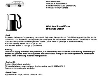
Fuel Reserve and Fuel Cap Placement Warning Lamp With the electronic key in steering lock position 2, the fuel reserve warning lamp comes on. It should go out immediately when the engine is running. If the warning lamp does not go out after starting the engine, or if it comes on while driving, it indicates that the fuel level is down to the reserve quantity of approximately 2.1 gal (8 liters). The warning lamp blinks when the fuel cap is not closed, or a fuel system leak has been detected. Retighten cap and see if lamp goes out. If the warning lamp continues to blink after closing the fuel cap correctly, have the fuel system checked at your authorized Mercedes-Benz dealer as soon as possible. Leaving the engine running and the fuel cap open can cause the "Check Engine" lamp to illuminate).
Tachometer Red marking on tachometer: Excessive engine speed. Avoid this engine speed, as it may result in serious engine damage that is not covered by the Mercedes-Benz Limited Warranty. For engine protection, the fuel supply is interrupted if the engine is operated within the red marking.
Seat Belt Warning Lamp With the electronic key in steering lock position 2, the warning lamp comes on, and a warning sounds for a short time if the drivers seat belt is not fastened. After starting the engine, the warning lamp blinks for a brief period to remind the driver and passengers to fasten seat belts.
Outside Temperature Indicator The temperature sensor is located in the front bumper area. Due to its location, the sensor can be affected by road or engine heat during idling or slow driving. This means that the accuracy of the displayed temperature can only be verified by comparison to a thermometer placed next, to the sensor, not by comparison to external displays (e.g. bank signs etc.). Adaptation to ambient temperature takes place in steps and depends on the prevailing driving conditions (stop-and- go or moderate, constant driving) and amount of temperature change.
Warning ! The outside temperature indicator is not designed to serve as an Ice-Warning Device and is therefore un- suitable for that purpose. Indicated temperatures just above the freezing point do not guarantee that the road surface is free of ice.
Coolant Temperature Gauge If the antifreeze mixture is effective to -22°F (-30°C), the boiling point of the coolant in the pressurized cooling system of your vehicle is approx. 266°F (130°C). During severe operating conditions and stop-and-go city traffic, the coolant temperature may rise close to the red marking. The engine should not be operated with the coolant temperature in the red zone. Doing so may cause serious engine damage which is not covered by the Mercedes-Benz Limited Warranty.
Warning ! • Driving when your engine is badly overheated can cause some fluids which may have Beaked into the engine compartment to catch fire. You could be seriously burned. • Steam from an overheated engine can cause serious burns and can occur just by opening the engine hood. Stay away from the engine if you see or hear steam coming from it. Turn off the engine, get out of the car and do not stand near the car until it cools down.
Low Engine Coolant Level Warning Lamp With the electronic key in steering lock position 2, the warning lamp comes on. It should go out when the engine is running. If the warning lamp does not go out after starting the engine, or if it comes on while driving, then the coolant level has dropped below the required level. If no leaks are noticeable and the engine temperature does not increase, continue to drive to the nearest service station and have coolant added to the coolant system (see Index). The low engine coolant level warning light should not be ignored. Extended driving with the light illuminated may cause serious engine damage not covered by the Mercedes-Benz Limited Warranty. In cases of major or frequent minor coolant loss, have the cooling system checked at your authorized Mercedes-Benz dealer as soon as possible.
Note: Do not drive without coolant in the cooling system. The engine will overheat causing major engine damage. Monitor the coolant temperature gauge while driving.
Warning !
Do not spill antifreeze on hot engine parts. Antifreeze contains ethylene glycol which may burn if it comes into contact with hot engine parts. You can be seriously burned.
Low Windshield and Headlamp Washer System Fluid Level Warning Lamp With the electronic key in steering lock position 2, the warning lamp comes on. It should go out when the engine is running. If the warning lamp does not go out after starting the engine, or if it comes on while driving, the level of the reservoir has dropped to approx.1/4 of the total volume. The reservoir should be refilled with MB Windshield Washer Concentrate "S" and water (or commercially available premixed windshield washer solvent/antifreeze, depending on ambient temperature - see Index) at the next opportunity. The reservoir for the windshield and headlamp washer systems is located in the engine compartment.
Exterior Lamp Failure Indicator Lamp With the electronic key in steering lock position 2, an indicator lamp comes on. It should go out when the engine is running. If the warning lamp does not go out after starting the engine, or if it comes on while driving, this lamp indicates a failure in the parking lamp, taillamp, stop lamp, or low beam headlamp. If an exterior lamp fails, the indicator lamp will come on only when that lamp is switched on. If a brake lamp fails, the lamp failure indicator will come on when applying the brake and stay on until the engine is turned off.
Note: If additional lighting equipment is installed (e.g. auxiliary headlamps etc.) be certain to connect into the fuse before the failure indicator monitoring unit in order to avoid damaging the system.
Brake Pad Wear Indicator Lamp With the electronic key in steering lock position 2, the brake pad wear indicator lamp comes on for approximately 30 seconds. It goes out when the engine is running. If the indicator lamp lights up during braking, this indicates that the brake pads are worn down. Have the brake system checked at your authorized Mercedes-Benz dealer as soon as possible.
Brake Warning Lamp With the electronic key in steering lock position 2, the brake warning lamp will come on. It should go out when the engine is running. The brake warning lamp will come on:
• when there is insufficient brake fluid in the reservoir (engine running and parking brake released), or • when the parking brake is set (engine running).
Warning ! Driving with the brake warning lamp on can result in an accident. Have your brake system checked immediately if the brake warning lamp stays on. Don't add brake fluid before checking the brake system. Overfilling the brake fluid reservoir can result in spilling brake fluid on hot engine parts and the brake fluid catching fire. You can be seriously burned.
If you find that the minimum mark on the brake fluid reservoir is reached, have the brake system checked for brake pad thickness and leaks. To test the brake warning lamp, turn electronic key in steering lock to position 2. The brake warning lamp comes on, and should go out when the engine is running.
Flexible Service System (FSS)
or
appears in the main odometer field prior to the next suggested service. Depending on operating
The FSS permits a flexible service schedule that is directly related to the operating conditions of the vehicle. The symbol conditions throughout the year, the next service is calculated and displayed in days or distance remaining. The message is displayed for approx. 10 seconds when turning the electronic key in steering lock to position 2, or it can be canceled manually by pressing button 0. Once the suggested term has passed, the message plus symbol or , preceded by a - (minus symbol) blinks, when turning the electronic key to position 2. The FSS display can also
be called up for approx.10 seconds with display illuminated by pressing button 0 twice. Following a completed service the Mercedes-Benz dealer sets the counter to 10 000 miles (Canada: 15 000 km) and 365 days.
The counter can also be set by any individual. To do so: 1. Turn electronic key in steering lock to position 2. 2. Within 4 seconds press button 0 twice. 3. The present status for days or distance is displayed. Within 10 seconds turn electronic key in steering lock to position 0. 4. Press and hold button 0, while turning electronic key in steering lock to position 2 again. The present status for days or distance is displayed once more. Continue to hold button 0 After approx. 10 seconds a signal sounds, and the display shows 10 000 miles (Canada: 15000 km). 5. Release button 0. If the FSS counter was inadvertently reset, have a Mercedes -Benz dealer correct it.
Notes: When disconnecting vehicle battery for one or more days at a time, such days will not be counted. Any such days not counted by the FSS can be added by your Mercedes-Benz dealer. The interval between services is determined by the kind of vehicle operation. Driving at extreme speeds, and cold starts combined with short distance driving in which the engine does not reach normal operating temperature, reduce the interval between services.
Model C 230: The FSS allows for distances between 10 000 miles (Canada: 15 000 km) and 15 000 miles (Canada: 22 500 km), or from 365 to 730 days between services.
Models C 280 and C 43 AMG: The FSS allows for distances between 10 000 miles (Canada: 15 000 km) and 20 000 miles (Canada: 30 000 km), or from 365 to 730 days between services. However you choose to set your reference numbers, the scheduled services as posted in the Service Booklet must be followed to properly care for your vehicle.
Antilock Brake System (ABS)
Important ! The ABS improves steering control of the vehicle during braking maneuvers. Do not pump the brake pedal, rather use firm, steady brake pedal pressure. Pumping the brake pedal defeats the purpose for ABS and significantly reduces braking effectiveness. The ABS prevents the wheels from locking up above a vehicle speed of approximately 5 mph (8 km/h) independent of road surface conditions. At the instant one of the wheels is about to lock up, a slight pulsation can be felt in the brake pedal, indicating that the ABS is in the regulating mode. Keep firm and steady pressure on the brake pedal while experiencing the pulsation. On slippery road surfaces, the ABS will respond even with light brake pedal pressure because of the increased likelihood of locking wheels. The pulsating brake pedal can be an indication of hazardous road conditions and functions as a reminder to take extra care while driving.
ABS Control The ABS malfunction indicator lamp in the instrument cluster comes on with the electronic key in steering lock position 2 and should go out when the engine is running. If the charging voltage falls below 10 volts, the malfunction indicator lamp comes on and the ABS is switched off. When the voltage is above this value again, the malfunction indicator lamp should go out and the ABS is operational. With the ABS malfunctioning, the ASR or ESP, if vehicle so equipped, are also switched off. Both malfunction indicator lamps come on with the engine running. If the ABS malfunction indicator lamp does not go out or comes on while driving, it indicates that the ABS has detected a malfunction and has switched off. In this case, the brake system functions in the usual manner, but without antilock assistance. Have the system checked at your authorized Mercedes-Benz dealer as soon as possible.
Warning ! ABS cannot prevent the natural laws of physics from acting on the vehicle, nor can it increase the traction made available by the road conditions. The ABS cannot prevent accidents, including those resulting from excessive speed in turns, following another vehicle too closely, or aquaplaning. Only a safe, attentive, and skillful driver can prevent accidents. The capabilities of an ABS equipped car must never be exploited in a reckless or dangerous manner which could jeopardize the user's safety or the safety of others.
Note: To alert following vehicles to slippery road conditions you discover, operate your hazard warning flashers as appropriate.
Brake Assist System (BAS)
Warning ! BAS cannot prevent the natural laws of physics from acting on the vehicle, nor can it increase braking efficiency beyond that afforded by the condition of the vehicle brakes and tires or the traction afforded. The BAS cannot prevent accidents, including those resulting from excessive speed in turns, following another vehicle too closely, or aquaplaning. Only a safe, attentive, and skillful driver can prevent accidents. The capabilities of a BAS equipped car must never be exploited in a reckless or dangerous manner which could jeopardize the user's safety or the safety of others.
The Brake Assist System is designed to maximize the vehicle's braking capability during emergency braking maneuvers by having maximum power boost applied to the brakes more quickly in emergency braking conditions than might otherwise be afforded solely by the driver's braking style. This can help reduce braking distances over what ordinary driving and braking style might do. The BAS complements the Antilock Brake System (ABS). To receive the benefit of the system you must apply continuous full braking power during the stopping sequence. Do not reduce brake pedal pressure. Once the brake pedal is released, the BAS is deactivated The indicator lamps for the ASR and ESP are combined with the BAS indicator lamp. The BAS/ASR or BAS/ESP malfunction indicator lamp in the instrument cluster corne on with the electronic key in steering lock position 2 and should go out with the engine running. If the BAS/ASR or BAS/ESP malfunction indicator lamp comes on permanently while the engine is running, a malfunction has been detected in either system. As a result, it is possible that now only partial engine output will be available, and pressing the accelerator pedal will require more effort. If the BAS malfunctions. The brake system functions in the usual manner, but without BAS. If the charging voltage falls below 10 volts, the malfunction indicator lamp comes on and the BAS is switched off. When the voltage is above this value again, the malfunction indicator lamp should go out and the BAS is operational. With the ABS malfunctioning, the BAS, ASR or ESP are also switched off. Both malfunction indicator lamps come on with the engine running. Have the BAS, ASR or ESP checked at your authorized Mercedes-Benz dealer as soon as possible.
Acceleration Slip Regulation (ASR) The acceleration slip regulation will engage at all vehicle speeds, if one or both drive wheels begin to lose traction and spin in acceleration. While engaged, the yellow warning lamp in the speedometer dial flashes. With the acceleration slip regulation engaged, the brake is applied to the spinning drive wheel until slip is brought under control. If both drive wheels spin, the brake is applied to both drive wheels and simultaneously, engine torque is limited, to improve the vehicle's driving stability. As traction on the road surface increases, thus allowing acceleration without slip, the allowable engine torque also increases again and the brake is no longer applied to drive wheels.
Important ! If the ASR warning lamp flashes, adapt your speed and driving to the prevailing road conditions.
Caution ! If the vehicle is towed with the front axle raised (see Towing the vehicle in Index), the engine must be shut off (electronic key in steering lock position 0 or 1). Otherwise, the acceleration slip regulation will immediately be engaged and will apply the rear wheel brakes.
Notes: The indicator lamp for the ASR is combined with that of the BAS The yellow BAS/ASR malfunction indicator lamp in the instrument cluster and the yellow ASR warning lamp in the speedometer dial come on with the electronic key in steering lock position 2. They should go out with the engine running. If the BAS/ASR malfunction indicator lamp comes on with the engine running, a malfunction has been detected in either system. Pressing the accelerator pedal will require greater effort. Only partial engine output will be available. If the BAS malfunctions, the brake system functions in the usual manner, but without BAS. Have the BAS or ASR checked at your authorized Mercedes-Benz dealer as soon as possible. With the ABS malfunctioning, the ASR is also switched off. Driving the vehicle with varied size tires will cause the wheels to rotate at different speeds, therefore the acceleration slip regulation may activate (yellow ASR warning lamp in speedometer dial comes on). For this reason, all wheels, including the spare wheel, must have the same tire size. When testing the parking brake on a brake test dynamometer, the engine must be shut off. Otherwise, the acceleration slip regulation will immediately be engaged and will apply the rear wheel brakes. In winter operation, the maximum effectiveness of the acceleration slip regulation is only achieved with Mercedes-Benz recommended M+S rated radialply tires and/or snow chains.
ASR Control Switch
ASR control switch located in center console To improve the vehicle's traction when driving with snow chains, or starting off in deep snow, sand or gravel, press the upper half of the ASR switch. The ASR warning lamp, located in the speedometer dial, is continuously illuminated. With the ASR system switched off, the engine torque reduction feature is cancelled. Therefore, the enhanced vehicle stability offered by ASR is unavailable. Adapt your speed and driving to the prevailing road conditions. A portion of the ASR system remains active, even with the switch in the OFF position. If one drive wheel loses traction and begins to spin, the brake is applied until the wheel regains sufficient traction. The traction control engages at vehicle speeds up to approximately 24 rnph (40 km/h), and switches off at 50 mph (80 km/h). Note: Avoid spinning of one drive wheel. Doing so may cause serious damage to the drive train which is not covered by the Mercedes-Benz Limited Warranty. The ASR warning lamp, located in the speedometer dial, starts to flash at any vehicle speed as soon as the tires lose traction and the wheels begin to spin. To return to the enhanced vehicle stability offered by ASR: press lower half of the switch (the ASR warning lamp in the speedometer dial goes out).
Important! If the ASR warning lamp flashes: • during take-off, apply as little throttle as possible, • while driving, ease up on the accelerator.
Electronic Stability Program (ESP) (optional)
The ESP enhances directional control and reduces driving wheel spin of the vehicle under any driving condition. Over/understeering of the vehicle is counteracted by applying brakes to the appropriate wheel to create a counterpointing vehicle movement. The ESP warning lamp, located in the speedometer dial, starts to flash.
Important ! If the ESP warning lamp flashes, adapt your speed and driving to the prevailing road conditions.
Caution ! If the vehicle is towed with the front axle raised (see Towing the vehicle in Index), the engine must be shut off (electronic key in steering lock position 0 or 1). Otherwise, the electronic stability program will immediately be engaged and will apply the rear wheel brakes.
Notes: The indicator lamp for the ESP is combined with that of the BAS. The yellow BAS/ESP malfunction indicator lamp in the instrument cluster and the yellow ESP warning lamp in the speedometer dial come on with the electronic key in steering lock position 2. They should go out with the engine running. If the BAS/ESP multifunction indicator lamp comes on permanently with the engine running, a malfunction has been detected in either system. Pressing the accelerator pedal will require greater effort. Only partial engine output will be available. If the BAS malfunctions, the brake system functions in the usual manner, but without BAS. Have the BAS or ESP checked at your authorized Mercedes-Benz dealer as soon as possible. With the ABS malfunctioning, the ESP is also switched off. Driving the vehicle with varied size tires will cause the wheels to rotate at different speeds, therefore the electronic stability program may activate (yellow ESP warning lamp in speedometer dial comes on). For this reason, all wheels, including the spare wheel, must have the same tire size. When testing the parking brake on a brake test dynamometer, the engine must be shut off. Otherwise, the electronic stability program will immediately be engaged and will apply the rear wheel brakes. In winter operation, the maximum effectiveness of the electronic stability program is only achieved with Mercedes-Benz recommended M+S rated radial-ply tires and/or snow chains.
ESP Control Switch
ESP control switch located on center console To improve the vehicle's traction when driving with snow chains, or starting off in deep snow, sand or gravel, press the upper half of the ESP switch. The ESP warning lamp, located in the speedometer dial, is continuously illuminated. With the ESP system switched off, the engine torque reduction feature is cancelled. Therefore, the enhanced vehicle stability offered by ESP is unavailable. Adapt your speed and driving to the prevailing road conditions. A portion of the ESP system remains active, even with the switch in the OFF position. If one drive wheel loses traction and begins to spin, the brake is applied until the wheel regains sufficient traction. The traction control engages at vehicle speeds up to approximately 24 mph (40 km/h), and switches off at 50 mph (80 km/h).
Note: Avoid spinning of one drive wheel. Doing so may cause serious damage to the drive train which is not covered by the Mercedes-Benz Limited Warranty. The ESP warning lamp, located in the speedometer dial, starts to flash at any vehicle speed as soon as the tires lose traction and the wheels begin to spin. To return to the enhanced vehicle stability offered by ESP: press lower half of the switch (the ESP warning lamp in the speedometer dial goes out).
Important ! If the ESP warning lamp flashes: • during take-off, apply as little throttle as possible, • while driving, ease up on the accelerator.
Emission Control Certain systems of the engine serve to keep the toxic components of the exhaust gases within permissible limits required by law. These systems, of course, will function properly only when maintained strictly according to factory specifications. Any adjustments on the engine should, therefore, be carried out only by qualified Mercedes-Benz authorized dealer technicians. Engine adjustments should not be altered in any way. Moreover, the specified service jobs must be carried out regularly according to Mercedes-Benz servicing requirements. For details refer to the Service Booklet.
Warning ! Inhalation of exhaust gas is hazardous to your health. All exhaust gas contains carbon monoxide, and inhaling it can cause unconsciousness and lead to death. Do not run the engine in confined areas (such as a garage) which are not properly ventilated. If you think that exhaust gas fumes are entering the vehicle while driving, have the cause determined and corrected immediately. If you must drive under these conditions, drive only with at least one window fully open.
On-Board Diagnostic System The Sequential Multiport Fuel Injection (SFI) control module monitors emission control components that either provide input signals to or receive output signals from the control module. Malfunctions resulting from interruptions or failure of any of these components are indicated by the "CHECK ENGINE" malfunction indicator lamp in the instrument cluster and are simultaneously stored in the diagnostic module. If the "CHECK ENGINE" malfunction indicator lamp comes on, have the system checked at your authorized Mercedes-Benz dealer as soon as possible. The control module switches off the "CHECK ENGINE" indicator lamp if the condition, causing the lamp to come on, no longer exists. An on-board diagnostic connector is located in the passenger compartment near to the parking brake pedal, allowing the accurate identification of system malfunctions through the readout of diagnostic trouble codes.
Winter Driving Have your car winterized at your authorized Mercedes-Benz dealer before the onset of winter. • Change the engine oil if the engine contains an oil which is not approved for winter operation. For viscosity (SAE/CCMC class) and filling quantity, see Capacities: Fuels, Coolants, Lubricants etc. in Index. • Check engine coolant anticorrosion/antifreeze concentration. • Additive for the windshield washer and headlamp cleaning system: Add MB Concentrate "S" to a premixed windshield washer solvent/antifreeze which is formulated for below freezing temperatures (see Index). • Test battery: Battery capacity drops with decreasing ambient temperature. A well charged battery helps to ensure that the engine can be started, even at low ambient temperatures. • Tires: We recommend M+S rated radial-ply tires on all four wheels for the winter season. Observe permissible maximum speed for M+S rated radial-ply tires and the legal speed limit.
Note: In winter operation, the maximum effectiveness of the acceleration slip regulation or of the electronic traction system can only be achieved with M+S rated radial-ply tires and/or snow chains recommended by Mercedes-Benz. Snow chains maximize performance.
Snow Chains Use only snow chains that are tested and recommended by Mercedes-Benz. Your authorized Mercedes-Benz dealer will be glad to advise you on this subject. Chains should only be used on the rear wheels. Follow the manufacturer's mounting instructions. Snow chains should only be driven on snow covered roads at speeds not to exceed 30 mph (50 km/h). Remove chains as soon as possible when driving on roads without snow. For tips on driving on slippery winter roads, refer to Index. Vehicles with Acceleration Slip Regulation (ASR) or Electronic Stability Program (ESP): When driving with snow chains, press the ASR or ESP control switch, refer to Index.
Model C 43 AMG
Important! Use of snow chains is permissible only on winter tire size 215/45 R 17 H M+S. Refer to "Rims - Tires" in section "Technical Data" (see Index).
Travelling Abroad Abroad, there is a widely-spread Mercedes-Benz service network at your disposal. If you plan to travel into areas which are not listed in the index of your dealer directory, you should request pertinent information from your authorized Mercedes-Benz dealer.
Hood
To open: To unlock the hood, pull release lever (1) under the driver's side of the instrument panel. At the same time handle (2) will extend out of the radiator grill (it may be necessary to lift the hood up slightly).
Caution ! To avoid damage to the windshield wiper or hood, open the hood only with wiper in the parked position. Pull handle (2) completely out of radiator grill and open hood (do not pull up on handle).
To close: Lower hood and let it drop into lock from a height of approx. 1 ft. (30 cm), assisting with hands placed flat on edges of hood (3). To avoid hood damage, if hood is not fully closed, repeat closing procedure. Do not push down on hood to attempt to fully close it.
Warning!
To help prevent personal injury, stay clear of moving parts when the hood is open and the engine is running. Be sure the hood is properly closed before driving. When closing hood, use extreme caution not to catch hands or fingers. The engine is equipped with a transistorized ignition system. Because of the high voltage it is dangerous to touch any components (ignition coils, spark plug sockets, diagnostic socket) of the ignition system • with the engine running, • while starting the engine, • if ignition is "on" and the engine is turned manually. If you see flames, steam or smoke coming from the engine compartment, or if the coolant temperature gauge indicates that the engine is overheated, do not open the hood. Move away from vehicle and do not open the hood until the engine has cooled. If necessary, call a fire department.
Example
Checking Coolant Level To check the coolant level, the vehicle must be parked on level ground and the engine stopped. Check coolant level only when coolant is cold.
Adding Coolant If coolant has to be added, a 50/50 mixture of water and MB anticorrosion/antifreeze should be added. The drain plugs for the cooling system are located on the right side of the engine block and at the bottom of the radiator. Anticorrosion/antifreeze, see Coolants in Index.
Warning! In order to avoid possibly serious burns: •Use extreme caution when opening the hood if there are any signs of steam or coolant leaking from the cooling system, or if the coolant temperature gauge indicates that the coolant is overheated. •Do not remove pressure cap on coolant reservoir if engine temperature is above 194°F (90°C). Allow engine to cool down before removing cap. The coolant reservoir contains hot fluid and is under pressure. •Using a rag, slowly open cap approximately 1/2 turn to relieve excess pressure. If opened immediately, scalding hot fluid and steam will be blown out under pressure. •Do not spill antifreeze on hot engine parts. Antifreeze contains ethylene glycol which may burn if it comes into contact with hot engine parts.
Checking Engine Oil Level
Example
1. Oil dipstick 2. Oil filler cap
To check the engine oil level, park vehicle on level ground, with engine at normal operational temperature. Check engine oil level approximately 5 minutes after stopping the engine, allowing for the oil to return to the oil pan.
Oil Dipstick: Wipe oil dipstick clean prior to checking the engine oil level. Fully insert dipstick in tube, and remove after three seconds to obtain accurate reading.
Oil level must be between the lower (min) and upper (max) mark of the dipstick.
Fill quantity between upper and lower dipstick marking level is approximately 2.1 US qt (2.0 I). Do not overfill the engine. Excessive oil must be drained or siphoned. It could cause damage to engine and catalytic converter not covered by the Mercedes-Benz Limited Warranty. For low engine oil level warning lamp, see Index.
Odometer Display Field (Models C 280 and C 43 AMG)
Turn electronic key in steering lock to position 2 and wait until the symbols odometer display field. Within 1 second press button 0 twice.
The following messages are available: "OK" "-1.0 Q" (Canada: -1.0 L) "-1.5 Q" (Canada: -1.5L) "-2.0 Q" (Canada: -2.0 L) Add oil to upper (max) mark of the dipstick."HI"
and
appears in the
Do not overfill the engine. Excessive oil must be drained or siphoned. It could cause damage to engine and catalytic converter not covered flashes in the odometer field if a proper oil level check by the Mercedes-Benz Limited Warranty. The symbol cannot be performed. The oil level check can be repeated after a short while. Perform the oil level check with the dipstick, if it cannot be completed via the odometer display field. In this case we recommend that you have the system checked at a Mercedes-Benz dealer.
Automatic Transmission Fluid Level The transmission has a permanent fill of automatic transmission fluid. Regular automatic transmission fluid level checks and changes are not required. For this reason the dipstick is omitted. If you notice fluid leaks or gear shifting malfunctions, have your authorized Mercedes-Benz dealer check the transmission fluid level.
Trunk Lamp If the trunk is to remain open for a long period of time, the trunk lamp can be switched off by pulling out the plunger in the switch (arrow). This prevents the vehicle battery from being discharged. When the trunk lid is closed, the switch will reset and turn on the lamp next time the lid is opened.
Stowing Things in the Vehicle
Warning ! To help avoid personal injury during a collision or sudden maneuver, exercise care when stowing things. Put luggage or cargo in the trunk if possible. Do not pile luggage or cargo higher than the seat backs. Do not place anything on the shelf below the rear window.
First Aid Kit
1. Opening lid The first aid kit is stored in the shelf below the rear window.
Spare Wheel, Vehicle Tools, Storage Compartment
1. Trunk floor 2. Handle 3. Luggage bowl 4. Vehicle tools 5. Tab
Lift trunk floor and engage handle in upper edge of the trunk. To remove spare tire: Turn luggage bowl counterclockwise and remove. To store spare tire: Place spare tire in wheel well and secure it with luggage bowl. Turn luggage bowl clockwise to its stop. The tab must point toward front of vehicle.
Note: Always lower trunk floor before closing trunk lid.
Vehicle Jack
1. Jack arm 2. Jack base
See illustration for proper storage of jack. Before storing the jack on the felt in the spare wheel well, the jack arm must be lowered almost to the base of the jack.
Warning ! The jack is designed exclusively for jacking up the vehicle at the jack tubes built into either side of the vehicle. To help avoid personal injury, use the jack only to lift the vehicle during a wheel change. Never get beneath the vehicle while it is supported by the jack. Keep hands and feet away from the area under the lifted vehicle. Always firmly set parking brake and block wheels before raising vehicle with jack. Do not disengage parking brake while the vehicle is raised. Be certain that the jack is always vertical when in use, especially on hills. Always try to use the jack on level surface. Be sure that the jack arm is fully inserted in the jack tube. Always lower the vehicle onto sufficient capacity jackstands before working under the vehicle.
Wheels Replace rims or tires with the same designation, manufacturer and type as shown on the original part. See your authorized Mercedes-Benz dealer for further information. See your authorized Mercedes- Benz dealer for information on tested and recommended rims and tires for summer and winter operation. They can also offer advice concerning tire service and purchase.
Tire Replacement Front tires should be replaced in sets. Furthermore - in the event of tire replacement - the spare wheel (except model C 43 AMG), if possible, should be used on the rear axle. Rims and tires must be of the correct size and type. For dimensions, see "Technical Data". We recommend that you break in new tires for approx. 60 miles (100 km) at moderate speed. It is imperative that the wheel mounting bolts be fastened to a tightening torque of 80 ft.lb. (110 Nm) whenever wheels are mounted. For rim and tire specifications, refer to "Technical Data".
Warning ! Worn, old tires can cause accidents. If the tire tread is badly worn, or if the tires have sustained damage, replace them. When replacing rims, use only genuine Mercedes-Benz wheel bolts specified for the particular rim type. Failure to do so can result in the bolts loosening and possibly an accident.
Rotating Wheels Rotation of wheels with summer tires does not apply to model C 43 AMG. The wheels can be rotated according to the degree of tire wear while retaining the same direction of travel. Rotating, however, should be carried out at the scheduled service intervals, before the characteristic tire wear pattern (shoulder wear on front wheels and tread center wear on rear wheels) becomes visible, as otherwise the driving properties
Important ! Unidirectional tires must always be mounted with arrow on tire sidewall pointing in direction of vehicle forward movement. Notes: Thoroughly clean the inner side of the wheels any time you rotate the wheels or wash the vehicle underside. The use of retread tires is not recommended. Retread tires may adversely affect the handling characteristics and safety of the vehicle. Dented or bent rims can cause tire pressure loss and damage to the tire beads. For this reason, check rims for damage at regular intervals. The rim flanges must be checked for wear before a tire is mounted. Remove burrs, if any. Check and correct tire inflation pressure after rotating the wheels. For Tire Inflation Pressure refer to Index.
Spare Wheel for Model C 43 AMG
The spare wheel rim size is 71/2Jx17H2 In the case of a flat tire or break- down, you may temporarily use a 71/2Jx17 H 2 instead of the 81/2J x 17 H 2 wheel rim on the rear axle, when observing the following restrictions: • Do not exceed vehicle speed of 50 mph (80 km/h). • Drive to the nearest repair facility to have the flat tire repaired or replaced as appropriate. For additional information, refer to "Technical Data".
1. Wheel bolt for model C 43 AMG 2. Wheel bolt for model 230 und C 28
Replace rims or tires with the same designation, manufacturer and type as shown on the original part. See your authorized Mercedes-Benz dealer for further information.
Warning ! The jack is designed exclusively for jacking up the vehicle at the jack tubes built into either side of the vehicle. To help avoid personal injury, use the jack only to lift the vehicle during a wheel change. Never get beneath the vehicle while it is supported by the jack. Keep hands and feet away from the area under the lifted vehicle. Always firmly set parking brake and block wheels before raising vehicle with jack. Do not disengage parking brake while the vehicle is raised. Be certain that the jack is always vertical when in use, especially on hills. Always try to use the jack on level surface. Be sure that the jack arm is fully inserted in the jack tube. Always lower the vehicle onto sufficient capacity jackstands before working under the vehicle.
Changing Wheels
Move vehicle to a level area which is a safe distance from the road way. 1. Set parking brake and turn on hazard warning flasher. 2. Move selector lever to position "P" and turn off engine. 3. Prevent vehicle from rolling away by blocking wheels with wheel chocks (not supplied with vehicle) or sizable wood block or stone. When changing a wheel on a hill, place chocks on the downhill side blocking both wheels of the other axle. On a level road, place one chock in front of and one behind the wheel that is diagonally opposite to the wheel being changed. 4. Using the wrench, loosen but do not yet remove the wheel bolts.
5. Remove the protective cover from the jack support tube opening by inserting the screwdriver (supplied in the tool kit) in the opening and prying it out. The tube openings are located directly behind the front wheel housings and in front of the rear wheel housings.
6. Insert jack arm fully into the tube hole up to the stop. Place jack on firm ground. Position the jack so that it is always vertical (plumb-line) as seen from the side (see arrow), even if the vehicle is parked on an incline. 7. Jack up the vehicle until the wheel is clear of the ground. Never start engine while vehicle is raised. 8. Unscrew upper-most wheel bolt and install alignment bolt (1) supplied in the tool kit. Remove the remaining bolts. Keep bolt threads protected from dirt and sand.
9. Remove wheel. Grip wheel from the sides. Keep hands from beneath the wheels. 10. Clean contact surfaces of wheel and wheel hub. Install spare wheel on wheel hub. Insert wheel bolts and tighten them slightly. To avoid paint damage, place wheel flat against hub and hold it there while installing first wheel bolt. Unscrew the alignment bolt (1) to install the last wheel bolt. 11. Lower car. Remove jack and insert jack tube cover. Before storing the jack, the jack arm must be lowered almost to the base of the jack.
Warning ! Always replace wheel bolts that are damaged or rusted. Never apply oil or grease to wheel bolts. Damaged wheel hub threads should be repaired immediately. Incorrect mounting bolts or improperly tightened mounting bolts can cause the wheel to come off. This could cause an accident. Be sure to use the correct mounting bolts.
12. Using the wrench, tighten the five bolts evenly, following the sequence illustrated above, until all bolts are tight. Observe a tightening torque of 80 ft.lb. (110 Nm). 13. Ensure proper tire pressure.
Tire Inflation Pressure A table (see fuel filler flap) lists the tire inflation pressures specified for Mercedes-Benz recommended tires as well as for the varying operating conditions.
Important ! Tire pressure changes by approx. 1.5 psi (0.1 bar) per 18°F (10°C) of air temperature change. Keep this in mind when checking tire pressure inside a garage - especially in the winter. Example: If garage temperature = approx. +68°F (+20°C) and ambient temperature = approx. +32°F (0°C) then the adjusted air pressure = specified air pressure +3 psi (+0.2 bar). Tire pressures listed for light loads are minimum values offering high driving comfort. Increased inflation pressures for heavy loads produce favorable handling characteristics with lighter loads arid are perfectly permissible. The ride of the vehicle, however, will become somewhat harder. Tire temperature and pressure increase with the vehicle speed. Tire pressure should therefore only be corrected on cold tires. Correct tire pressure in warm tires only if pressure has dropped below the pressure listed in the table and the respective operating conditions are taken into consideration. An underinflated tire due to a slow leak (e.g. due to a nail in the tire) may cause damage such as tread separation, bulging etc.. Regular tire pressure checks (including the spare tire) at intervals of no more than 14 days are therefore essential. If a tire constantly loses air, it should be inspected for damage.
Warning ! Do not overinflate tires. Overinfiating tires can result in sudden deflation (blowout) because they are more likely to become punctured or damaged by road debris, potholes etc.. Follow recommended inflation pressures. Do not overload the tires by exceeding the specified vehicle capacity weight (as indicated by the label on the driver's door latch post). Overloading the tires can overheat them, possibly causing a blowout.
Exterior Lamps Headlamp Adjustment
Correct headlamp adjustment is extremely important. Check and readjust headlamps at regular intervals and when a bulb has been replaced.
Headlamp Assembly 1. Cover for low beam headlamp bulb, fog lamp, and level for vertical adjustment 2. Latch for cover (1) 3. Cover for high beam headlamp bulb 4. Clamp for cover (3) 5. Headlamp vertical adjustment screw
6. Headlamp horizontal adjustment screw 7. Scale for horizontal adjustment 8. Electrical connector for low beam headlamp bulb Xenon lamp (optional) ignition module for low beam 9. Electrical connector for fog lamp bulb 10. Electrical connector for high beam headlamp bulb
Replacing Bulb: To prevent a possible electrical short circuit, switch off lamp prior to replacing a bulb. When replacing bulbs, install only 12 volt bulbs with the specified watt rating. When replacing halogen bulbs do not touch glass portion of bulb with bare hands. Use plain paper or a clean cloth.
Warning ! Halogen lamps contain pressurized gas. A bulb can explode if you: • touch or move it when hot, • drop the bulb, • scratch the bulb. Wear eye and hand protection.
Bulb for Low Beam H7 (55 W) Bulb for Fog Lamp H1 (55 W)
Open hood. Depress latch (2) and remove cover (1). Pull of electrical connector (8) or (9). Unhook clamping ring and removes bulb. Insert new bulb (seating properly in cutouts of bulb socket), and mount clamping ring. Reinstall and push electrical connector on securely. Reinstall bottom end of cover (1) and push against top end of cover until properly seated. Check lamp for proper operation.
Xenon (optional) Bulb for Low Beam
Warning ! Because of high voltage in Xenon lamps, it is dangerous to replace the bulb or repair the lamp and its components. We recommend that you have such work done by a qualified technician.
Bulb for High Beam H1 (55 W) Open hood. Move retaining clamps (4) aside and remove cover (3). Pull off electrical connector (10). Unhook clamping ring and pull out bulb together with clamping ring. Remove bulb. Insert new bulb (seating properly in cutouts of bulb socket), mount clamping ring. Reinstall and push electrical connector on securely. Reinstall cover and fasten with retaining clamp (4).
Turn Signal, Parking, Side Marker and Standing Lamp (2357 NA [28.5/8.3 W/30/2.2 cp bulb]) Open hood. Squeeze latch (1) together and lift complete lamp assembly out to front of vehicle. Twist bulb socket (2) counterclockwise and pull out. Push bulb into socket, turn counterclockwise and remove. Insert new bulb in socket push in and twist clockwise. Reinstall bulb socket. Reinstall lamp assembly by sliding tabs (3) into guides (4) until properly seated.
1. Latch for turn signal, parking, side marker, and standing lamp assembly 2. Bulb socket for turn signal, parking, side marker, and standing lamp 3. Tab 4. Guide
Adjusting Headlamp Aim (Halogen)
Correct headlamp adjustment is extremely important. To check and readjust a headlamp do the following: • Horizontal aim will change and must be corrected as described below, whenever a vertical adjustment is made. • Low beam adjustments simultaneously aim the high beam and fog lamp. • Vehicle should have a normal trunk load.
1. Park vehicle on level surface approximately 6 inches (152 mm) from a vertical test screen or wall. The centerline of the vehicle must be at a 90° angle to the test screen. 2. Using a "T" square and a carpenter's level, align and mark avertical centerline (8) on the test screen using the outer reference point (low centerlines should be 47 1/4 inches (1198 mm). 3. Move vehicle on the level surface 25 feet (7.6 m) straight back from the wall. 4. Open hood, depress latch (1), and remove access cover (2) from the headlamp. 5. Vertical headlamp aim (low beams on): Turn adjusting screw (3) (counterclockwise to adjust headlamp downward, clockwise upward) until bubble in the level (4) is centered on the "0" mark. Graduations: 0.18° pitch.
6. Horizontal headlamp aim (low beams on): Turn adjusting screw (5) (Right front headlamp: counterclockwise to adjust to the left, clockwise to the right; left front headlamp: counterclockwise to adjust to the right, clockwise to the left.) until the headlamps (low beam) illuminate the test screen as shown. The vertex of the angle formed in each beam image should align with the vertical centerline (8) of each lamp. The left and right headlamps must be adjusted individually.
7. The indicator (6) in the sight glass should align with the "0" mark after any horizontal adjustment. If it does not, slide the "0" mark on the scale (7) until it aligns with the indicator (6). Graduations: 0.38° pitch. 8. Reinstall access cover(2).
Adjusting Headlamp Aim (Xenon)
Correct headlamp adjustment is extremely important. To check and readjust a headlamp, follow steps 1 through 5. Please note: • Low beam adjustments simultaneously aim the high beam. • Vehicle should have a normal trunk load. • Vertical aim adjustments change horizontal aim.
1. Park vehicle on level surface approximately 25 feet (7.6 m) from a vertical test screen or wall. The centerline of the vehicle must be at a 90° angle to the test screen. 2. (low beams on) Using a "T" square and a carpenter's level, align and mark a vertical centerline (8) on the test screen using the vertex of the angle formed in each beam image. As a check, the distance between centerlines should be 471/4inches(1198mm).
3. Mark a horizontal centerline (9) at a height of 221/2 inches (570 mm) on the test screen. It must be at a 90° angle to the vertical centerline. 4. Open hood. 5. Vertical headlamp aim (low beams on): Turn adjusting screws (1 and 2) equally in direction and turns (counterclockwise to adjust headlamp downward, clockwise upward) until the headlamps (low beam) illuminate the test screen as shown. The left and right headlamps must be adjusted individually.
Note: If it is not possible to obtain a proper headlamp adjustment, have the system checked at your authorized Mercedes-Benz dealer.
Taillamp Assemblies
1. Stop lamp (21 W/32 cp bulb) 2. Turn signal lamp (21 W/32 cp bulb) 3. Backup lamp (21 W/32 cp bulb) 4. Tail, parking, side marker and standing lamp (5 W/4 cp bulb) 5. Passenger side: Tail and parking lamp (21/4W bulb) Driver's side: Tail, parking and rear fog lamp (21/4 bulb)
To replace bulbs: From inside trunk, open locks and swing open lamp cover. Turn locking lever on lamp to horizontal position and remove bulb carrier. Push down on bulb to be changed, twist counterclockwise and remove.
Battery
Warning ! Failure to follow these instructions can result in severe injury or death. Never lean over batteries while connecting, you might get injured. Battery fluid contains sulfuric acid. Do not allow this fluid to come in contact with eyes, skin or clothing. In case it does, immediately flush affected area with water and seek medical help if necessary. A battery will also produce hydrogen gas, which is flammable and explosive. Keep flames or sparks away from battery, avoid improper connection of jumper cables, smoking etc..
Important ! Battery maintenance information: The battery is located in the trunk under the trunk floor. The fluid level must be checked at every A and B service. Always insure that the fluid level is at the specified maximum level and that only distilled water is used. Failure to maintain proper fluid level may result in cell deterioration and possible battery rupture. The service life of the battery is dependent on its condition of charge. The battery should always be kept sufficiently charged, in order to last an optimum length of time. Therefore, we strongly recommend that you have the battery charge checked frequently, and corrected if necessary, especially if you use the vehicle less than approximately 200 miles (300 km) per month, mostly for short distance trips, or if it is not used for long periods of time. Only charge a battery with a battery charger after the battery has been disconnected from the vehicle electrical circuit. Always disconnect the battery negative lead first and connect last. When removing and connecting the battery, always make sure that all electrical consumers are off and the electronic key is in steering lock position 0. The battery and its vent tube must always be securely installed when the car is in operation. While the engine is running the battery terminal clamps must not be loosened or detached, otherwise the generator and other electronic components would be damaged.
Note: After reconnecting the battery also resynchronize the Express feature of the power windows (see Power Windows in Index).
Battery Recycling Batteries contain materials that can harm the environment with improper disposal. Large 12 Volt storage batteries contain lead. Recycling of batteries is the preferred method of disposal. Many states require sellers of batteries to accept old batteries for recycling.
Fuses
1. Main fuse box in engine compartment
2. Auxiliary fuse box in trunk 3. Auxiliary fuse in trunk 4. Auxiliary fuse in engine compartment
Before replacing a blown fuse, determine the cause of the short circuit. Spare fuses are supplied inside the main fuse box. Observe amperage and color of fuse. To gain access to the main fuse box, release clamp (1), lift the fuse box cover up and remove it. A special fuse puller comes with the vehicle tools. Always use a new fuse for replacement. Never attempt to repair or bridge a blown fuse. After replacing a blown fuse, close fuse box cover. To close the main fuse box, engage cover at the rear and secure with clamp.
Jump Starting
Warning ! Failure to follow these directions will cause damage to the electronic components, and can lead to a battery explosion and severe injury or death. Never lean over batteries while connecting or jump starting, you might get injured. Battery fluid contains sulfuric acid. Do not allow this fluid to come in contact with eyes, skin or clothing. In case it does, immediately flush affected area with water, and seek medical help if necessary. A battery will also produce hydrogen gas, which is flammable and very explosive. Keep flames or sparks away from battery, avoid improper connection of jumper cables, smoking etc.. Read all instructions before proceeding.
If the battery is discharged, the engine should be started with jumper cables and the (12 V) battery of another vehicle. The battery is located in the trunk under the trunk floor.
Proceed as follows: 1. Position the vehicle with the charged battery so that the jumper cables will reach, but never let the vehicles touch. Make sure the jumper cables do not have loose or missing insulation. 2. On both vehicles: • Turn off engine and all lights and accessories, except hazard warning flashers or work lights. • Apply parking brake and shift selector lever to position "P".
Important ! 3. Clamp one end of the first jumper cable to the positive (+) terminal of the discharged battery and the other end to the positive (+) terminal of the charged battery. Make sure the cable clamps do not touch any other metal parts. 4. Clamp one end of the second jumper cable to the grounded negative (-) terminal of the charged battery and the final connection to the negative (-) terminal of the discharged battery.
Important ! 5. Start engine of the vehicle with the charged battery and run at high idle. Make sure the cables are not on or near pulleys, fans, or other parts that will move when the engine is started. Allow the discharged battery to charge for a few minutes. Start engine of the disabled vehicle in the usual manner. 6. After the engine has started, remove jumper cables exactly reversing the above installation sequence, starting with the last connection made first. When removing each clamp, make sure that it does not touch any other metal while the other end is still attached.
Important ! A discharged battery can freeze at approx. +14°F (-10°C). In that case, it must be thawed out before jumper cables are used. A frozen battery can explode and cause personal injury.
Jumper cable specifications: • Minimum cable cross-section of 25 mm2 or approx. 2 AWG • Maximum length of 11.5 ft. (3.5 m).
All except C 43 AMG
C 43 AMG
Towing the Vehicle
The rear towing eye is located at the right, below the bumper. The front towing eye is located on the passenger side behind a cover in the bumper panel.
Models C 230 and C 280: Cover removal: Insert finger in recess on left end of cover and pull cover out. Cover installation: Engage cover at top right and press cover in securely.
Model C 43 AMG: Cover removal: Hold left and right end of grille and pull out. Cover installation: Engage cover at bottom and press in top securely. We recommend that the vehicle be transported using flat bed equipment. This method is preferable to other types of towing. The vehicle may be towed with all wheels on the ground and the selector lever in position "N" for distances up to 30 miles (50 km) and at a speed not to exceed 30 mph (50 km/h). The electronic key must be in steering lock position 2. To positively avoid a possibility of damage to the transmission, however, we recommend to disconnect the drive shaft at the rear axle drive flange on any towing beyond a short tow to a nearby garage. Do not tow with sling-type equipment. Towing with sling-type equipment over bumpy roads will damage radiator and supports. Use wheel lift, dolly, or flat bed equipment, with electronic key in steering lock turned to position 0.
Warning ! With the engine not running, there is no power assistance for the braking and steering systems, in this case, it is important to keep in mind that a considerably higher degree of effort is necessary to brake and steer the vehicle.
Note: To signal turns while being towed with hazard warning flasher in use, turn electronic key in steering lock to position 2 and activate combination switch for left or right turn signal in usual manner - only the selected turn signal will operate. Upon cancelling the turn signal, the hazard warning flasher will operate again.
Caution ! Vehicles with Acceleration Slip Regulation (ASR) If the vehicle is towed with the front axle raised, the engine must be shut off (electronic key in steering lock position 0 or 1). Otherwise, the ASR will immediately be engaged and will apply the rear wheel brakes.
Caution ! Vehicles with Electronic Stability System (ESP) If the vehicle is towed with the front axle raised, the engine must be shut off (electronic key in steering lock position 0 or 1). Otherwise, the ESP will immediately be engaged and will apply the rear wheel brakes.
Cleaning and Care of the Vehicle
Warning ! Many cleaning products can be hazardous. Some are poisonous, others are flammable. Always follow the instructions on the particular container. Always open your car's doors or windows when cleaning the inside. Never use fluids or solvents that are not designed for cleaning your car.
In operation, your vehicle is subjected to varying external influences which, if gone unchecked, can attack the paintwork as well as the underbody and cause lasting damage. Such damage is caused not only by extreme and varying climatic conditions, but also by air pollution, road salt, tar, gravel and stone chipping. Grease and oil, fuel, coolant, brake fluid, bird droppings, insects, tree resins etc. should be removed immediately to avoid paint damage. Frequent washing reduces and/or eliminates the aggressiveness and potency of the above adverse influences. More frequent washings are necessary to deal with unfavorable conditions; for example, near the ocean, in industrial areas (smoke, exhaust emissions), or during winter operation. You should check your vehicle from time to time for stone chipping or other damage. Any damage should be repaired as soon as possible to prevent the start of corrosion. In doing so, do not neglect the underside of the car. A prerequisite for a thorough check is a washing of the underbody followed by a thorough inspection. Damaged areas need to be reundercoated. Your vehicle has been treated at the factory with a wax-base rustproofing in the body cavities which will last for the lifetime of the vehicle. Post-production treatment is neither necessary nor recommended by Mercedes-Benz because of the possibility of incompatibility between materials used in the production process and others applied later. We have selected car care products and compiled recommendations which are specially matched to our vehicles and which always reflect the latest technology. You can obtain Mercedes- Benz approved car care products at your authorized Mercedes-Benz dealer. Scratches, corrosive deposits, corrosion or damage due to negligent or incorrect care cannot always be removed or repaired with the car care products recommended here. In such cases it is best to seek aid at your authorized Mercedes-Benz dealer. The following topics deal with the cleaning and care of your vehicle and give important "how-to" information as well as references to Mercedes-Benz approved car care products. Additional information can be found in the booklet titled "Car Care".
Engine Cleaning Prior to cleaning the engine compartment make sure to protect electrical components and connectors from the intrusion of water and cleaning agents. Corrosion protection, such as MB Anticorrosion Wax should be applied to the engine compartment after every engine cleaning. Before applying, all control linkage bushings and joints should be lubricated. The poly-V-belt and all pulleys should be protected from any wax.
Car Washing Do not use hot water or wash your car in direct sunlight. Use only a mild car wash detergent, such as Mercedes-Benz approved Car Shampoo. Thoroughly spray the car with a diffused jet of water. Direct only a very weak spray towards the ventilation intake. Use plenty of water and rinse the sponge and chamois frequently. Rinse with clear water and thoroughly wipe dry with a chamois. Do not allow cleaning agents to dry on the finish. If the vehicle has been run through an automatic car wash - in particular one of the older installations - rewipe the recessed sections in the taillamps (designed to prevent soiling) if necessary. No solvents (fuels, thinners etc.) must be used. In the winter, thoroughly remove all traces of road salt as soon as possible. When washing the underbody, do not forget to clean the inner sides of the wheels.
Tar Stains Quickly remove tar stains before they dry and become more difficult to remove. A tar remover is recommended.
Window Cleaning Use a window cleaning solution on all glass surfaces. An automotive glass cleaner is recommended.
Wiper Blade Clean the wiper blade rubber with a clean cloth and detergent solution. Replace blade twice a year; once before and once after winter.
Headlamp Cleaning System The condition of the wiper blades is important for satisfactory cleaning of the headlamp lenses. We therefore recommend that the blades be inspected regularly. Replace damaged wiper blades.
Paintwork. Painted Body Components Mercedes-Benz approved Paint Care should be applied when water drops on the paint surface do not "bead up"; normally in 3 to 5 months, depending on climate and washing detergent used. Mercedes-Benz approved Paint Cleaner should be applied if paint surface shows signs of dirt embedding (i.e. loss of gloss). Do not apply any of these products or wax if your car is parked in the sun or if the hood is still hot. Use the appropriate MB-Touch-Up Stick for quick and provisional repairs of minor paint damage (i.e. chips from stones, car doors etc.).
Seat Belts The webbing must not be treated with chemical cleaning agents. Use only clear, lukewarm water and soap. Do not dry the webbing at temperatures above 176°F (80°C) or in direct sunlight.
Warning ! Do not bleach or dye seat belts as this may severely weaken them. In a crash they may not be able to provide adequate protection.
Hard Plastic Trim Items Pour Mercedes-Benz approved Interior Care onto soft lint-free cloth and apply with light pressure.
Headliner and Shelf below Rear Window Clean with soft bristle brush, or use a dry-shampoo cleaner in case of excessive dirt.
Plastic and Rubber Parts Do not use oil or wax on these parts.
Steering Wheel and Gear Selector Lever Wipe with a damp cloth and dry thoroughly or clean with Mercedes-Benz approved Leather Care.
Light Alloy Wheels Mercedes-Benz approved Wheel Care should be used for regular cleaning of the light alloy wheels. If possible, clean wheels once a week with Mercedes-Benz approved Wheel Care, using a soft bristle brush and a strong spray of water. Follow instructions on container.
Note: Use only acid-free cleaning materials. The acid could lead to corrosion.
Ornamental Moldings For regular cleaning and care of very dirty chrome-plated parts, use a chrome cleaner.
Upholstery Using aftermarket seat covers or wearing clothing that have the tendency to give off coloring (e.g. when wet etc.) may cause the upholstery to become permanently discolored. By lining the seats with a proper intermediate cover, contact-discoloration will be prevented. Leather Upholstery Wipe leather upholstery with a damp cloth and dry thoroughly or clean with Mercedes-Benz approved Leather Care. Exercise particular care when cleaning perforated leather as its underside should not become wet. MB Tex Upholstery Pour Mercedes-Benz approved Interior Care onto soft lint-free cloth and apply with light pressure.
Instrument Cluster Use a gentle dish-washing detergent or mild detergent for delicate fabrics as a washing solution. Wipe with a cloth moistened in lukewarm solution. Do not use scouring agents.
Electronic Main Key Remote Control
1. Transmit buttons 2. Lamp for battery check and function control
Checking Batteries: If one of the transmit buttons is pressed, the function control lamp briefly illuminates - indicating that the batteries are in order. Change batteries if the function control lamp does not come on.
Changing Batteries: Move lock (1) in direction of right arrow and slide out mechanical key (2, left arrow). Insert mechanical key (2) in side opening (3). Press briefly (do not use key as lever) to release battery compartment. Remove mechanical key. Lift battery compartment (4) slightly in direction of arrow (5) and remove in direction of arrow (6). Change batteries (7), inserting new ones under contact spring (8) with plus (+) side facing up. Return battery compartment into housing until locked in place.
Important ! Batteries contain materials that can harm the environment if disposed of improperly. Recycling of batteries is the preferred method of disposal. For disposal, please follow manufacturer's recommendation on battery package. Replacement battery: Lithium, type CR 2025 or equivalent.
Synchronizing Remote Control: The remote control may have to be resynchronized, if the vehicle cannot be locked or unlocked. To synchronize insert electronic key in steering lock. The remote control should once again be operational.
Front Head Restraints
Warning ! For your protection, drive only with properly positioned head restraints. Adjust head restraint to support the back of the head approximately at ear level. Do not drive the vehicle without the seat head restraints. Head restraints are intended to help reduce injuries during an accident.
For positioning of head restraints refer to sections Manual Seats, Power Seats, and Head Restraints, Rear in Index.
Power seats Removal: Push button (1) up to bring the head restraint to its highest position. Pull out head restraint completely with both hands. Installation: Push button (1) up for approximately 5 seconds. Insert head restraint and push it down to the stop. Adjust head restraint, see Index.
Manual seat Removal: Pull head restraint up to the stop. Push button (1) and pull head restraint out. Installation: Insert the head restraint and push it down to the stop. Adjust head restraint, see Index.
Rear Seat Cushion
Removal: Push in locking tabs (on left and right side of seat) and pull up seat at the front. Installation: Slide rear edge of cushion under the backrest. Push front of cushion down until it locks in place.
Caution! Watch out for sharp edges when removing or installing the rear seat cushion, and make sure that it is securely locked in place again, to prevent personal injury.
Emergency Operation of Sliding/Pop-Up Roof
The sliding/pop-up roof can be opened or closed manually should an electrical malfunction occur. The sliding/pop-up roof drive is located behind the lens of the left interior lamp between the sun visors. 1. Pry off lens (1) by using a screw driver. 2. Obtain crank (2) (supplied with vehicle) and insert it through hole.
To slide the roof closed or to raise the roof at the rear: turn crank clockwise. To slide the roof open or to lower the roof at the rear: turn crank counterclockwise.
Replacing Wiper Blade Insert
For safety reasons, remove electronic key from steering lock before replacing the wiper blade, otherwise the motor can suddenly turn on and cause injury.
Notes: Do not open engine hood with wiper arm folded forward. Do not allow the wiper arm to contact the windshield glass without a wiper blade inserted. The glass may be scratched or broken. Make certain that the wiper blade is properly installed. An improperly installed blade may cause windshield damage.
Removal: Fold wiper arm forward. Press safety tab down (1), push wiper blade downward (2) and remove. Place wiper blade on firm support. Slide (direction of arrow) the wiper blade insert out of the retainer claws.
Headlamp Wiper Blades
Removal: Fold wiper arm forward. Push pin (1) and remove wiper blade.
Installation: Place wiper blade on wiper arm and press in pin (1).
Installation: Slide (direction of arrow) wiper blade insert into retainer claws until tabs are engaged. Insert wiper blade between tabs (3) on the wiper arm, and slide into end of wiper arm. Press safety tab upward until it locks in place.
Manual Release of Fuel Filler Flap
The manual release knob is located behind the right side trunk panel and felt pad. In case the central locking system does not release the fuel filler flap, pull the manual release knob while simultaneously opening the fuel filler flap.
Use only those roof racks approved by Mercedes-Benz to avoid damage to the vehicle. Follow manufacturer's installation instructions. Mount supports only between markings on border of roof which are visible when doors are opened.
Roof Rack
C230
C 280, C 43 AMG
Layout of Poly-V-belt Drive
1. Automatic belt tensioner 2. Crankshaft 3. Air conditioning compressor 4. Generator (alternator)
5. Idler pulley 6. Power steering pump 7. Coolant pump, fan
For dimensions of the poly-V-belt, see Technical Data in Index.
Spare Parts Service
All authorized Mercedes-Benz dealers maintain a stock of original spare parts required for maintenance and repair work. In addition, strategically located parts distribution centers provide quick and reliable parts service. More than 300,000 different spare parts, for other Mercedes-Benz models, are available. Mercedes-Benz original spare parts are subjected to the most stringent quality inspections. Each part has been specifically developed, manufactured or selected for and adapted to Mercedes-Benz vehicles. Therefore, Mercedes-Benz original spare parts should be installed.
Important !
The use of non-genuine parts and accessories not authorized by Mercedes-Benz could damage the vehicle or compromise its durability or safety.
Identification Labels
When ordering spare parts, please specify vehicle identification and engine numbers. 1 Certification Label 2 Vehicle Identification No. 3 Identification Label lower edge of windshield) 4 Engine No. C 230, rear left, C 280, rear right, C 43 AMG, rear right 5 Body No. and Paintwork No. 6 Emission Control Label 7 Information Label California version Vacuum line routing for emission control system
Warranty Coverage
Your car is covered under the terms of the "warranties" printed in the Owner's Service and Warranty Information booklet and your authorized Mercedes-Benz dealer will exchange or repair any defective parts in accordance with the terms of the following warranties:
1. New vehicle limited warranty 2. Emission systems warranty 3. Emission performance warranty 4. California emission control systems warranty.
Loss of Owner's Service and Warranty Information Booklet Should you lose your Owner's Service and Warranty Information booklet, have your authorized Mercedes-Benz dealer arrange for a replacement. It will be mailed to you.
Technical Data C 230 Model Engine Mode of operation
No. of cylinders Bore Stroke Total piston displacement Compression ratio Output acc. to SAE J 1349
Maximum torque acc. to SAE J 1349 Maximum engine speed Firing order Poly-V-belt Main Dimensions Overall vehicle length Overall vehicle width Overall height Wheel base Track, front Track, rear Weights Roof load max. Trunk load max
C 230 (202 023)1 111 4-stroke engine, gasoline injection 3.58 in (90.90 mm) 3.48 in (88.40 mm) 140.1 cu.in. (2295 cm3) 10,4:1 148 hp/5500 rpm (110 kW/5500 rpm) 162 ft.lb./4000 rpm (220 Nm/40OOrpm) 6000 rpm 1-3-4-2 2155 mm
177.4 in (4507 mm) 67.7 in (1720mm) 56.1 in (1424 mm) 105.9 in (2690 mm) 59.0 in (1499 mm) 57.6 in (1464mm) See certification tag 220 lb(100 kg) 220 lb(100 kg)
7J x 15 H 2 1.46 in (37 mm)
205/60 R 15 91 H 205/60 R 15 91 T M+S
61/2J x 15 H 2 1.46 in (37 mm) 195/65 R 15 91 H
Rims - Tires Rims (light alloy rims) Wheel offset All season;Radial-ply tires Winter tires;Radial-ply tires Model C 230- Canada only Rims (steel rims) Wheel offset All season;Radial-ply tires Winter tires;Radial-ply tires 195/65 R 15 91 T M+S Electrical System Generator (alternator) Starter motor Battery Spark plugs
Electrode gap Tightening torque
14 V/90 A 12 V/1.4KW 12 V/100 Ah Bosch F 9 DCO Beru 14 F-9 DUO
Champion C 12 YCC 0.032 in (0,8 mm) 15-22ft.lb. (20-30 Mm)
1 The quoted data apply only to the standard vehicle. See an authorized Mercedes-Benz dealer for the correspon-ding data of ali special bodies and special equipment,
Technical Data C 280 Model Engine
Mode of operation
No. of cylinders
Bore
Stroke
C 280 (202 029)1 112
4-stroke engine, gasoline injection
3.54 in (89.90 mm)
2.89 in (73.50 mm)
Total piston displacement 170.8 cu.in. (2799 cm3)
Compression ratio
10:1
Output acc. to SAE J 1349 Maximum torque acc. to SAE J 1349
195 hp/5800 rpm (145 kW/5800 rpm) 195 ft.lb./3000 rpm (265 Nm/3000rpm)
Maximum engine speed 6000 rpm Firing order 1-4-3-6-2-5
Poly-V-belt
2390 mm
Weights: See certification tag
220 lb(100 kg)
220 lb(100 kg)
Roof load max.
Trunk load max.
14 V/90 A
7J x 15 H 2
12 V/1.7KW
1.46 in (37 mm)
205/60R 15 91 H
205/60 R 15 91 T M+S
7J x 16 H 2 1.46 in (37 mm)
205/55 R 16 91 H
Rims - Tires Rims (light alloy rims) Wheel offset Summer tires; Radial-ply tires Winter tires; Radial-ply tires Rims and All season Tires ( Sport Package) Rims (light alloy rims) Wheel offset Summer tires; Radial-ply tires Electrical System Generator (alternator) Starter motor Battery Spark plugs Electrode gap Tightening torque Main Dimensions Overall vehicle length Overall vehicle width Overall height Wheel base Track, front Track, rear 57.6 in (1464mm) 1 The quoted data apply only to the standard vehicle. See an authorized Mercedes-Benz dealer
for the correspon-ding data of ali special bodies and special equipment,
Bosch F 9 DPER 0.032 in (0,8 mm) 15-22ft.lb. (20-30 Mm)
105.9 in (2690 mm)
177.4 in (4507 mm)
59.0 in (1499 mm)
56.1 in (1424 mm)
67.7 in (1720mm)
12 V/100 Ah
Technical Data C 43 AMG Model Engine
C 43 AMG (202 033)1 113
Mode of operation
4-stroke engine, gasoline injection
No. of cylinders
Bore
Stroke
3.54 in 89.90 mm)
3.31 in (84.00 mm)
Total piston displacement 260.0 cu.in. (4265 cm3) Compression ratio
10:1
Output acc. to SAE J 1349 Maximum torque acc. to SAE J 1349
302 hp/5850 rpm (225 kW/5850 rpm) 302ft.lb./3250 rpm (410 Nm/3250rpm)
Maximum engine speed Firing order
6300 rpm 1-5-4-2-6-3-7-8
Poly-V-belt
2390 mm
Weights
See certification tag
71/2J x 17 H 2 1.38 in (35 mm) 215/45 R 17 H M + S 225/45 R 17 H M + S 3
71/2J x 17 H 2 1.38 in (35 mm)
225/45 ZR 173