- 2009 Jeep Liberty Owners Manuals
- Jeep Liberty Owners Manuals
- 2011 Jeep Liberty Owners Manuals
- Jeep Liberty Owners Manuals
- 2010 Jeep Liberty Owners Manuals
- Jeep Liberty Owners Manuals
- 2007 Jeep Liberty Owners Manuals
- Jeep Liberty Owners Manuals
- 2008 Jeep Liberty Owners Manuals
- Jeep Liberty Owners Manuals
- 2005 Jeep Liberty Owners Manuals
- Jeep Liberty Owners Manuals
- 2004 Jeep Liberty Owners Manuals
- Jeep Liberty Owners Manuals
- Download PDF Manual
-
“Work”, “Mobile”, or “Pager”). This will allow you to have multiple numbers for each phonebook entry. † Recite the phone number for the phonebook entry that
you are adding.
After you are finished adding an entry into the phone- book, you will be given the opportunity to add more phone numbers to the current entry or to return to the main menu.
The UConnect™ system will allow you to enter up to 32
names into the phonebook with each name having up to four associated phone numbers and designations. Edit Entries in the UConnect™ Phonebook † Press the ’Phone’ button to begin. † After the 9Ready9 prompt, say 9Phonebook Edit9. † You will then be asked for the name of the phonebook † Next, choose the number designation that you wish to edit. The choices are home, work, mobile, or pager. † Recite the new phone number for the phonebook entryentry that you wish to edit.
that you are editing.
After you are finished editing an entry in the phonebook, you will be given the opportunities to edit another entry in the phonebook, call the number you just edited, or return to the main menu.
Phonebook edit can be used to add another phone number to a name entry that already exists in the phonebook. For example, the entry John Doe may have a mobile and a home number, but you can add John Doe’s work number later through phonebook edit. Delete Entries in the UConnect™ Phonebook † Press the ’Phone’ button to begin. † After the 9Ready9 prompt, say 9Phonebook Delete9. † After you enter the phonebook delete menu, you will then be asked for the name of the phonebook entry that you wish to delete. You can either say the name of a phonebook entry that you wish to delete or you can say 9List Names9 to hear a list of the entries in the phonebook from which you can choose. To select one of the entries from the list, press the 9Voice Recogni- tion9 button while the UConnect™ system is playing the desired entry and say 9Delete9.
UNDERSTANDING THE FEATURES OF YOUR VEHICLE 83
† After you enter the name, the UConnect™ system will ask you if you wish to delete the home, work, mobile, or pager number for this entry.
Delete All Entries in the UConnect™ Phonebook † Press the ’Phone’ button to begin. † After the 9Ready9 prompt, say 9Phonebook Delete All9. † The UConnect™ system will ask you to verify that you † After confirmation, the phonebook entries will be
wish to delete all the entries from the phonebook.
deleted.
List All Names in the UConnect™ Phonebook † Press the ’Phone’ button to begin. † After
the 9Ready9 prompt, say 9Phonebook List
Names9.
84 UNDERSTANDING THE FEATURES OF YOUR VEHICLE
phonebook entries.
† The UConnect™ system will play the names of all the † To call one of the names in the list, press the ’Voice Recognition’ button during the playing of the desired name and say 9Call9. † The UConnect™ system will then prompt you as to number designation you wish to call. † The selected number will be dialed. Phone Call Features The following feature(s) can be accessed through the UConnect™ system if the feature(s) are available on your cellular service plan. For example, if your cellular service plan provides three-way calling, this feature can be accessed through the UConnect™ system.
Answer or Reject an Incoming Call - No Call Currently in Progress When you receive a call on your cellular phone, the UConnect™ system will interrupt the stereo audio and will ask if you would like to answer the call by pressing the ’Phone’ button. Press the ’Phone’ button to answer the call. To reject the call, press the ’Phone’ button until you hear a single beep indicating that the incoming call was rejected. Answer or Reject an Incoming Call - Call Currently in Progress If a call is currently in progress and you have another incoming call, press the ’Phone’ button to place the current call on hold and answer the incoming call. To reject the incoming call, you can disregard the call and continue with your current conversation.
Making a Second Call while Current Call in Progress To make a second call while you are currently in a call, press the ’Voice Recognition’ button and say 9Dial9 or 9Call9 followed by the phone number or phonebook entry you wish to call. The first call will be on hold while the second call is in progress. Putting a Call on Hold and Retrieving a Call from Hold To put a call on hold, press the ’Phone’ button until you hear a single beep which will indicate that the call has been placed on hold. To bring the call back from hold, press the ’Phone’ button. Toggling Between Two Calls If two calls are in progress (one active and one on hold), press the ’Phone’ button until you hear a single beep
UNDERSTANDING THE FEATURES OF YOUR VEHICLE 85
indicating that the active and hold status of the two calls have switched. Only one call can be placed on hold at one time. Conference Call When two calls are in progress (one active and one on hold), press the ’Phone’ button until you hear a double beep indicating that the two calls have been joined into one conference call. Three-Way Calling To initiate three-way calling, press the ’Voice Recogni- tion’ button while a call is in progress and make a second phone call. When the second call is established, press the ’Phone’ button until you hear a double beep indicating that the two calls have been joined into one conference call. Call Termination To end a call in progress, press the ’Phone’ button. All calls in progress will be terminated.
86 UNDERSTANDING THE FEATURES OF YOUR VEHICLE
Phone Redial † Press the ’Phone’ button to begin. † After the 9Ready9 prompt, say 9Redial9. † The UConnect™ system will call the last number that was dialed on your cellular phone. This may not be the last number dialed by your UConnect™ system.
Advanced Phone Connectivity
Transferring an Active Call between the UConnect™ System and Your Cellular Phone The UConnect™ system allows ongoing calls to be trans- ferred to your cellular phone or to the UConnect™ system without terminating the call. To transfer an ongo- ing call from your cellular phone to the UConnect™ system or vice versa, press the ’Voice Recognition’ button and say 9Transfer Call9.
Delete Paired Cellular Phones † Press the ’Phone’ button to begin. † After the 9Ready9 prompt, say 9Setup Phone Pairing9. † At the next prompt, say 9Delete9. † You will be asked to say the name of the phone that you wish to delete. You can either say the name of the phone that you wish to delete or you can say 9All9 to delete all the phones.
Connect or Disconnect the Connection between the UConnect™ System and Your Cellular Phone Your cellular phone can be paired with many different electronic devices, but can only be actively 9connected9
with one electronic device at a time.If you would like to connect or disconnect the Blue- tooth™ connection between a paired cellular phone and the UConnect™ system, follow the instruction described in your cellular phone user’s manual. List Paired Cellular Phone Names † Press the ’Phone’ button to begin. † After the 9Ready9 prompt, say 9Setup List Phones9 and the UConnect™ system will play the phone names of all paired cellular phones in order from highest prior- ity to lowest priority.
Select a Lower Priority Paired Cellular Phone † Press the ’Phone’ button to begin. † After the 9Ready9 prompt, say 9Setup Select Phone9. † When prompted, say the phone name of the cellular phone you wish to use, or say 9List Phones9 to hear a list of all the phones that have been paired to your
UNDERSTANDING THE FEATURES OF YOUR VEHICLE 87
UConnect™ system. To select a phone from the list, press the ’Voice Recognition’ button and say 9Select9. † The lower priority phone will only be used for the next phone call. After that, the UConnect™ system will return to using the highest priority phone in the vehicle.
UConnect™ System Features
Barge In - Touch Tone Phone Inputs You can use your UConnect™ system to access a voice mail system, an automated service, or any other phone number that you can dial with any phone. When calling a number with your UConnect™ system that normally requires you to enter in a touch-tone sequence on your cellular phone keypad, you can push the ’Voice Recogni- tion’ button and say the sequence you wish to enter followed by 9Send9. For example, if required to enter your pin number, you can press the ’Voice Recognition’ button and say 93 7 4 6 Send9, or whatever you have made your
88 UNDERSTANDING THE FEATURES OF YOUR VEHICLE
pin. This method can also be used in instances where you are pressing a number on your keypad to navigate through a menu structure or to enter a number for a pager. Barge In - Overriding Prompts The ’Voice Recognition’ button can be used when you wish to skip part of a prompt and issue your voice recognition command immediately. For example, if a prompt is playing 9Would you like to pair a phone, clear a{9, you could press the ’Voice Recognition’ button and say 9Pair A Phone9 to select that option without having to listen to the rest of the voice prompt. Language Selection To change the language that the UConnect™ system is using, press the ’Phone’ button and say the name of the language you wish to switch to (English, Español, or
Français as equipped). After selecting one of the lan- guages, all prompts and voice commands will be in the selected language. Turning Confirmation Prompts On/Off Turning confirmation prompts off will stop the system from confirming your choices (e.g. the UConnect™ sys- tem will not repeat a phone number before you dial it). † Press the ’Phone’ button to begin. † After the 9Ready9 prompt, say 9Setup Confirmation9. The UConnect™ system will play the current confir- mation prompt status and you will be given the choice to change it.
Low Signal, Battery Strength, and Roam Notification The UConnect™ system will provide notification to inform you if your cellular phone is in roaming status, has low signal strength, or has a low battery when you are trying to place a phone call. Dialing Using the Cellular Phone Keypad You can dial a phone number with your cellular phone keypad and still use the UConnect™ system. By dialing a number with your paired Bluetooth™ cellular phone, the audio will be played through your vehicle’s stereo sys- tem. The UConnect™ system will work the same as if you dialed the number using voice recognition. Mute/Unmute When you mute the UConnect™ system, you will still be able to hear the conversation coming from the other party, but the other party will not be able to hear you. In order to mute the UConnect™ system press the ’Voice
UNDERSTANDING THE FEATURES OF YOUR VEHICLE 89
Recognition’ button and say 9Mute9. In order to unmute the UConnect™ system; press the ’Voice Recognition’ button and say 9Unmute9. Help If you need assistance at any prompt or if you want to know what your options are at any prompt, say 9Help9. The UConnect™ system will play all the options at any prompt if you ask for help. Cancel At any prompt, you can say 9Cancel9 and you will be returned to the previous menu. Emergency Assistance If you are in an emergency, say 9Dial Emergency9 or 9Call Emergency9 and the UConnect™ system will instruct your cellular phone to call 911.
90 UNDERSTANDING THE FEATURES OF YOUR VEHICLE
Towing Assistance If you need towing assistance, say 9Dial Towing Assis- tance9 or 9Call Towing Assistance9. Please refer to the 24-Hour Towing Assistance coverage details in the DaimlerChrysler Motors Company 24-Hour Towing As- sistance Program Guide.
SEATS
Front Seat (Manual) Adjustment Move the seat forward or rearward using the adjustment bar. Lift up on the bar located on the front of the seat near the floor. Position the seat and be sure the latch engages fully.
Using body pressure, move forward and rearward on the seat to be sure the seat adjusters have latched.
UNDERSTANDING THE FEATURES OF YOUR VEHICLE 91
Front Seat Adjustment — Recline To adjust the seatback, lift the lever located on the outboard side of the seat, lean back, and release the lever at the desired position. To return the seatback, lift the lever, lean forward, and release the lever.
WARNING!
† Adjusting a seat while the vehicle is moving is dangerous. The sudden movement of the seat could cause you to lose control. The seat belt might not be properly adjusted and you could be injured. Adjust any seat only while the vehicle is parked. † Do not ride with the seatback reclined so that the seat belt is no longer resting against your chest. In a collision you could slide under the seat belt and be seriously or even fatally injured. Use the re- cliner only when the vehicle is parked.
92 UNDERSTANDING THE FEATURES OF YOUR VEHICLE
Head Restraints Head restraints can reduce the risk of whiplash injury in the event of impact from the rear. Adjustable head restraints should be adjusted so that the upper edge is as high as practical. The head restraints have a locking button that must be pushed inward to lower the head restraint. The restraints may be raised without pushing in the button.
UNDERSTANDING THE FEATURES OF YOUR VEHICLE 93
Power Seat Adjuster — If Equipped
WARNING!
Do not ride with the seatback reclined so that the seat belt is no longer resting against your chest. In a collision you could slide under the seat belt and be seriously or even fatally injured. Use the recliner only when the vehicle is parked.
6–Way Power Seat with Manual Recliner The seat switch is on the outboard side of the seat near the floor. Use this switch to move the seat up or down, forward or rearward, or to tilt the seat.
94 UNDERSTANDING THE FEATURES OF YOUR VEHICLE
This seat also has a manual recline lever located just to the rear of the power seat switch. Pull up on the lever to recline the seat.
65/35 Split Folding Rear Seat To provide additional storage area, each rear seat can be folded flat to allow for extended cargo space and still maintain some rear seating room. NOTE: Prior to folding the rear seat, it may be necessary to reposition the front seat to it’s mid-track position. Also, be sure that the front seats are fully upright and positioned forward. This will allow the rear seat to fold down easily.
WARNING!
† It is extremely dangerous to ride in a cargo area, inside or outside of a vehicle. In a collision, people riding in these areas are more likely to be seriously injured or killed. † Do not allow people to ride in any area of your vehicle that is not equipped with seats and seat belts. † Be sure everyone in your vehicle is in a seat and
using a seat belt properly.
UNDERSTANDING THE FEATURES OF YOUR VEHICLE 95
To fold the 65/35 rear seat, perform the following steps: 1. Locate the seatback release handle on the outboard top side of each rear seatback; lift up on the handle, and rotate the lever forward until the seatback releases. Fold the seatback completely forward.
96 UNDERSTANDING THE FEATURES OF YOUR VEHICLE
NOTE: When lifting up on the release handle, the seatback will release easier if you do not pull forward on the seatback; only lift up on the release handle until the seatback disengages, then fold the seat forward. When the seatback is folded completely forward, the head restraints should be flush against the seat cushion.
To restore the 65/35 rear seat to the upright position perform the following steps: Raise the seatback and lock it into place. If interference from the cargo area prevents the seatback from fully locking, you will have difficulty returning the seat to its proper position.
WARNING!
Be certain that the seatback is securely locked into position. If the seatback in not securely locked into position the seat will not provide the proper stability for child seats and/or passengers. An improperly latched seat could cause serious injury.
Heated Seats — If Equipped The heated seat switch is located on the outboard side of the front seats. Pressing this switch to its desired setting (HI or LO) will activate the respective heating element for the heated seat.
UNDERSTANDING THE FEATURES OF YOUR VEHICLE 97
TO OPEN AND CLOSE THE HOOD To open the hood, two latches must be released. First pull the hood release lever inside your vehicle located under the left side of the instrument panel.
Once the heated seat switch is activated, depressing it a second time will de-activate it.
98 UNDERSTANDING THE FEATURES OF YOUR VEHICLE
Then, reach under the hood and slide the safety latch to the right and lift the hood.
To prevent possible damage, do not slam the hood to close it. Lower the hood until it is open approximately 12
inches (30 cm) and then push hood closed. This should secure both latches. Never drive your vehicle unless the hood is fully closed, with both latches engaged.WARNING!
If the hood is not fully latched, it could fly up when the vehicle is moving and block your forward vision. Be sure all hood latches are latched fully before driving.
LIGHTS
Interior Lights The overhead lights will come on when a door is opened, and when the rotating ring on the multi-function control lever is in a position other than OFF. They may also be turned on by rotating the control for the dimmer switch on the multi-function control lever fully upward or by pressing the “Unlock” button on the keyfob.
The overhead lights will automatically turn off in about 8
minutes if a door is left open or the dimmer control is left in the dome light position. Turn the ignition switch ON to restore the overhead light operation. Rear Cargo Light The rear cargo light includes an independent “On/Off” switch, which when “off” will not allow the illumination of any interior lighting when the rear swing gate or flipper glass is opened. All other methods of turning the interior lighting on/off will function normally regardless of the rear cargo light switch position.UNDERSTANDING THE FEATURES OF YOUR VEHICLE 99
Dimmer Control With the park lights or headlights on, rotating the control for the dimmer switch on the multi-function control lever upward will increase the brightness of the instrument panel lights. Rotating the control completely upward turns on the dome light. Daytime Brightness Feature Certain components (odometer, radio, etc.) can be illumi- nated at full brightness during the daytime. This can be helpful when driving with your headlights on during the daytime such as in a parade or a funeral procession. To activate this feature, rotate the multi-function control lever one detent lower than the dome light.
100 UNDERSTANDING THE FEATURES OF YOUR VEHICLE
Front Map/Reading Lights
These lights are mounted in the overhead console. Each light can be turned on by pressing the recessed area of the lens. To turn these lights off, press the recessed area of the lens a second time.
Multi-Function Control Lever The multi-function control lever controls the operation of the park lights, headlights, headlight beam selection, passing light, fog lights, instrument panel light dimming, and turn signals.
Parking Lights, Instrument Panel Lights, and Headlights Turn the end cap of the multi-function control lever to the first detent for parking lights and instrument panel lights. Turn to the second detent for headlight operation. To change the brightness of the instrument panel lights, rotate the center portion of the multi-function control lever up or down. High Beam/Low Beam Select Switch Pull the multi-function control lever towards you to switch the headlights to HIGH beam. Pull the multi- function control lever a second time to switch the head- lights to LOW beam. The “High Beam Indicator Light” will illuminate when the high beams are on.
UNDERSTANDING THE FEATURES OF YOUR VEHICLE 101
Passing Light You can signal another vehicle with your headlights by lightly pulling the multi-function control lever toward the steering wheel. This will cause the headlights to turn on at high beam and remain on until the lever is released. The “High Beam Indicator Light” will illuminate when the high beams are on. Turn Signals Move the multi-function control lever up or down and the arrows on each side of the instrument cluster flash to show proper operation of the front and rear turn signal lights. You can signal a lane change by moving the lever partially up or down without moving beyond the detent. If either light flashes at a very fast rate, check for a defective outside light bulb. If an indicator fails to light when the lever is moved, it would suggest that the fuse or indicator is defective.
102 UNDERSTANDING THE FEATURES OF YOUR VEHICLE
NOTE: A tone will chime if the turn signals are left on for more than 2 miles (3.2 km). Lights-On Reminder A chime will sound if the driver’s door is left open, and the headlights or parking lights are left on. Battery Saver Feature — Exterior Lights If the park lights, headlights, fog lights, or high beams are left on when the ignition switch is in the OFF position, the battery saver feature will automatically turn off the exterior lights after eight minutes. Normal operation will resume when the ignition is turned ON or when the switch is turned to another position.
Fog Lights — If Equipped
The front fog light switch is in the multi-function control lever. To activate the front fog lights, turn on the park or low beam headlights and pull out the end of the lever. The “Fog Light Indicator Light” will illuminate when the fog lights are on. NOTE: The fog lights will only operate with the park lights or the headlights on low beam. Selecting high beam headlights will turn off the fog lights. Daytime Running Lights — If Equipped The headlights come on at a low intensity level after the engine has started. They will turn off when the vehicle is turned off, when the headlights are switched on, or when the parking brake is set.
Light Bar — If Equipped
1. Remove lamp covers by pressing the thumb tab up- wards, and pulling the cover off.
UNDERSTANDING THE FEATURES OF YOUR VEHICLE 103
CAUTION!
The auxiliary lights mounted on the off road light bar should be illuminated during (OFF-ROAD USE ONLY.( Having them illuminated on public streets, highways, roads, etc. may be illegal in your state. Your state may also require auxiliary lights be cov- ered when operating your vehicle on the public streets, highways, roads, etc. Further, illuminating these lights with the supplied covers installed could cause permanent damage to the light bar. Before using these auxiliary lights, contact your State Au- thorities for proper operation and use of these lights.
104 UNDERSTANDING THE FEATURES OF YOUR VEHICLE
2. With the ignition in the ON position, press the button to turn on the light bar (located on the instrument panel to the left of the steering column). Press the button again to turn off the light bar.
To reinstall lamp covers, insert the tab under the top center lip of the lamp housing. Rotate the cover until snap fit is aligned with notch in the bottom center of the housing. Push cover until it is securely snapped (flush) in the housing.
WINDSHIELD WIPERS AND WASHERS The wipers and washers are operated by a switch on the control lever. This control lever is located on the right side of the steering column. For front wiper operation, turn the control lever end cap upward to select the desired wiper speed.
An indicator light in the instrument cluster will illumi- nate when the light bar has been activated.
3
UNDERSTANDING THE FEATURES OF YOUR VEHICLE 105
If vehicle is equipped with the optional Elec- NOTE: tronic Vehicle Information Center (EVIC) in the overhead console, all warnings including “door”, “GATE”, “GLASS”, and “LOWASH” will only be displayed in the EVIC display (not in the instrument cluster). For addi- tional information, refer to “Overhead Console — If Equipped” in Section 3. The vacuum fluorescent (VF) display located in the odometer area displays the word “LOWASH” when the washer solvent needs to be refilled. If the vehicle is not moving, when a low washer fluid condition is detected, the VF display will show the word “LOWASH” and then show the odometer/trip odometer mileage (each for 2
seconds). The display will continue to cycle. If any other active warnings including “door”, “GATE”, or “GLASS” are present, they will be shown in the VF display and will continue to cycle. If the vehicle starts moving, two single chimes will occur (one chime for eachWindshield Washers To use the washer, pull the lever toward you and hold while spray is desired. If the lever is pulled while in the delay range, the wiper will operate for two wipe cycles after the lever is released, and then resume the intermit- tent interval previously selected.
106 UNDERSTANDING THE FEATURES OF YOUR VEHICLE
complete display cycle). After this, the display will continue to sequence. After fifteen “LOWASH” se- quences, the VF display will no longer provide this warning. If the trip/reset button is pressed while the VF warnings are being displayed, the VF display will revert back to only displaying the odometer/trip odometer mileage. Once the warning is removed from the display, it will not return for the duration of the ignition cycle. If the lever is pulled while in the OFF position, the wipers will operate for several wipe cycles, then turn off. Mist Feature Push down on the wiper lever to activate a single wipe to clear off road mist or spray from a passing vehicle. As long as the lever is held down, the wipers will continue to operate.
CAUTION!
In cold weather, always turn off the wiper switch and allow the wipers to return to the park position before turning off the engine. If the wiper switch is left on and the wipers freeze to the windshield, damage to the wiper motor may occur when the vehicle is restarted.
Windshield Wiper Operation Turn the control lever end cap upward to the middle mark (sixth detent) for Low speed wiper operation, or to the upper mark (seventh detent) for High speed opera- tion.
UNDERSTANDING THE FEATURES OF YOUR VEHICLE 107
Intermittent Wiper System
Use the intermittent wiper when weather conditions make a single wiping cycle, with a variable pause be- tween cycles, desirable. Move the control lever to any of the first five wiper switch positions by turning the end cap of the control lever. The delay can be regulated from a maximum of approximately 18 seconds between cycles, to a cycle every second.
TILT STEERING COLUMN To tilt the column, push down on the lever below the turn signal control and move the wheel up or down, as desired. Pull the lever back towards you and firmly push the lever until it is above the lower surface of the shroud to lock the column in place.
108 UNDERSTANDING THE FEATURES OF YOUR VEHICLE
WARNING!
Tilting the steering column while the vehicle is moving is dangerous. Without a stable steering col- umn, you could lose control of the vehicle and have an accident. Adjust the column only while the ve- hicle is stopped. Be sure it is locked before driving.
ELECTRONIC SPEED CONTROL When engaged, this device takes over accelerator opera- tions at speeds greater than 35 mph (60 km/h). The controls are mounted on the steering wheel and consist of ON·OFF, SET, RES·ACCEL, CANCEL, and COAST con- trols.
To Activate Press and release the ON·OFF button to turn the system on. To turn the system off, press the ON·OFF button again. The system should be turned off when not in use. The CRUISE indicator light in the instrument cluster illuminates when the system is on.
To Set At A Desired Speed When the vehicle has reached the desired speed, press and release the SET button. Release the accelerator and the vehicle will operate at the selected speed. To Deactivate
A soft tap on the brake pedal, normal braking, or pressing the CANCEL button will deactivate the Speed Control without erasing the memory. Pressing the ON·OFF but- ton or turning off the ignition erases the memory. To Resume Speed To resume a previously set speed, press and release the RES·ACCEL button. Resume can be used at any speed above 30 mph (50 km/h).
UNDERSTANDING THE FEATURES OF YOUR VEHICLE 109
To Vary The Speed Setting When the Speed Control is on and set, speed can be increased by pressing and holding the RES·ACCEL but- ton. When the button is released, a new set speed will be established. Tapping the RES·ACCEL button once will result in a 2
mph (3 km/h) speed increase. Each time the button is tapped, speed increases, so tapping the button three times will increase speed by 6 mph (9 km/h), etc. To decrease speed while speed control is on and set, press and hold the COAST button. Release the button when the desired speed is reached, and the new speed will be set. To Accelerate for Passing Depress the accelerator as you would normally. When the pedal is released, the vehicle will return to the set speed.110 UNDERSTANDING THE FEATURES OF YOUR VEHICLE
NOTE: When driving uphill, at elevations above 2,000
ft. (610 meters), or when the vehicle is heavily loaded (especially when towing) the vehicle may slow below the SET speed. (If the vehicle speed drops below 30 mph (48
km/h), the Speed Control will automatically disengage). If this happens, you can push down on the accelerator pedal to maintain the desired speed. A full throttle (high RPM) acceleration, while the system is engaged, will cause the system to disengage. Vehicles may exhibit several 4-3 downshifts under the above conditions. To reduce the frequency of the down- shifts and to improve vehicle performance, it is advisable to lock out overdrive. Press the O/D OFF button on the right side of the shift lever.WARNING!
Leaving the Speed Control on when not in use is dangerous. You could accidentally set the system or cause it to go faster than you want. You could lose control and have an accident. Always turn the system off when you are not using it.
OVERHEAD CONSOLE — IF EQUIPPED The overhead console contains dome/reading lights, an optional universal garage door opener (HomeLinkt), an optional sunroof switch, and an Electronic Vehicle Infor- mation Center (EVIC) that consists of the following: † Compass/temperature display † Trip information displays † Vehicle information warning message displays † Customer programmable features
Pressing the MENU button will change the displayed programming features. Pressing the STEP button will select the available choices. Pressing the C/T (Compass/ Temperature) button will return the display to the normal compass/temperature display. NOTE: Temperature accuracy can be effected from heat soak. For best accuracy, the vehicle should be driven at a speed greater than 20 mph (32 km/h) for several min- utes. Dome/Reading Lights
Located in the overhead console are two dome/reading lights.
UNDERSTANDING THE FEATURES OF YOUR VEHICLE 111
The dome/reading lights illuminate when a door or the swing gate is opened or when the interior lights are turned on by rotating the dimmer control located on the multi-function lever. The reading lights are activated by pressing on the recessed area of the corresponding lens.
112 UNDERSTANDING THE FEATURES OF YOUR VEHICLE
NOTE: The dome/reading lights will remain on until the switch is pressed a second time, so be sure they have been turned off before leaving the vehicle. Electronic Vehicle Information Center The electronic vehicle information center (EVIC), when the appropriate conditions exist, displays the following messages and symbols. Each message is accompanied by a series of beeps: † DRIVER DOOR OPEN † PASSENGER DOOR OPEN † N DOORS OPEN (N = 2, 3, 4) † RIGHT REAR DOOR OPEN † REARGATE OPEN † LEFT REAR DOOR OPEN † LIFTGLASS OPEN
† TURN SIGNAL ON (with graphic) † PERFORM SERVICE † WASHER FLUID LOW † REMOTE KEY BATTERY LOW † NO J1850 BUS MSGS RECEIVED † LEFT FRONT LOW PRESSURE † LEFT FRONT HIGH PRESSURE † RIGHT FRONT LOW PRESSURE † RIGHT FRONT HIGH PRESSURE † LEFT REAR LOW PRESSURE † LEFT REAR HIGH PRESSURE † RIGHT REAR LOW PRESSURE † RIGHT REAR HIGH PRESSURE
† SPARE LOW PRESSURE † SPARE HIGH PRESSURE † TIRE PRESSURE UNAVAILABLE † TIRE PRESSURE NOW AVAILABLE † TIRE SENSOR BAD/MISSING † SPARE SWAP DETECTED Tire Pressure Monitor System The Tire Pressure Monitor (TPM) system uses wireless technology to monitor tire pressure levels. Sensors, mounted to each wheel as part of the valve stem transmit tire pressure readings to a receiver located in the over- head console. The tire pressure is shown in the Electronic Vehicle Information Center (EVIC) display. The TPM system remains active even if it is not displayed in the EVIC.
UNDERSTANDING THE FEATURES OF YOUR VEHICLE 113
CAUTION!
The TPM system is designed to monitor your tire pressure and will not function as a tire pressure gauge while adjusting the pressure in your tires. There will be a delay between the instant you adjust the air pressure in a tire and when the system updates the display.
NOTE: The TPM system can inform you about a low or high tire pressure condition, but it does not replace normal tire maintenance. The TPM system is not intended to provide you with notification of rapid pressure loss. 1. If any tire pressure has exceeded the low or high pressure (refer to STARTING AND OPERATING — TIRES AND WHEELS), the TPM system will display a message in the EVIC and sound a chime. It will then go
114 UNDERSTANDING THE FEATURES OF YOUR VEHICLE
into the tire pressure display screen and flash the pres- sure value of the tire that is low or high. This will be displayed for the rest of the ignition cycle, or until the C/T, MENU, STEP, or RESET button is pressed. NOTE: This display will return 60 seconds after the C/T, MENU, STEP, or RESET button is pressed. If a tire is low or high, you should correct your tire inflation pressure as soon as possible and inspect all of your tires. Refer to STARTING AND OPERATING — TIRES AND WHEELS for more details. Once the low or high tire pressure message has occurred, it will continue to blink until the tire pressure is cor- rected. 2. If the spare tire pressure has exceeded the low or high pressure allowed, the TPM system will display a message in the EVIC for 60 seconds and sound a chime each ignition cycle.
NOTE: This message will return every ignition cycle, until the tire pressures are corrected. 3. When the vehicle is moving and the EVIC cannot receive a valid sensor signal from the tire pressure sensors, the TIRE PRESSURE UNAVAILABLE message will be displayed for 3 seconds along with a chime. The display will then shift to the individual tire pressure display screen and display dashes for the tire or tires that are affected. If the TIRE PRESSURE UNAVAILABLE message has been displayed, and valid sensor signals are received, the EVIC will display the TIRE PRESSURE NOW AVAILABLE message for 3 seconds along with a chime. This is meant to inform you when the TPM system has returned to it’s normal operation. This will occur when valid tire pressure sensor messages have been received from all 4 road tires. TPM system function may be temporarily unavailable due to external electromag- netic interference, such as electronic devices or nearby radio or TV towers.
4. In addition to monitoring the vehicle tires, the TPM system monitors faults within the system. When any fault has been set, the TPM system will display TIRE SENSOR BAD/MISSING. Be sure to inspect your tires for proper inflation pressure. After you determine that your tires are properly inflated, see your authorized dealer for service to diagnose the problem with the TPM system. 5. If a road tire is replaced by the spare, the TPM system will automatically detect the tires have been switched (after the ignition has been cycled) and display SPARE SWAP DETECTED along with a chime. This could take up to 10 minutes with vehicle speed above 25
mph (40 km/h). General Information This device complies with FCC rules part 15 and with RSS-210 of Industry Canada. Operation is subject to the following conditions: 1. This device may not cause harmful interferencethat
UNDERSTANDING THE FEATURES OF YOUR VEHICLE 115
2. This device must accept any interference that may be received, including interference that may cause undes- ired operation Changes or modifications not expressly approved by the party responsible for compliance could void the user’s authority to operate the device. For further assistance, questions, or comments about the TPM system, please call 1–877–774–8473. Customer Programmable Features Press the MENU button until one of the display choices following appears: Language? When in this display you may select one of five lan- guages for all display nomenclature, including the trip computer functions. Press the STEP button while in this display to select English, Francais, Deutsch, Italiana, or Espanol. As you continue the displayed information will be shown in the selected language.
116 UNDERSTANDING THE FEATURES OF YOUR VEHICLE
Display U.S. or Metric? Pressing the STEP button when in this display selects US or Metric. The overhead console and instrument panel displays will be in the selected units. Auto Door Locks? When this feature is selected, all doors and the swing gate will lock automatically when the speed of the vehicle reaches 15 mph (25 km/h). Pressing the STEP button when in this display will select “Yes” or “No.” Auto Unlock On Exit? (Available Only When the AUTO DOOR LOCKS Feature is Turned On ) When this feature is selected all the vehicle’s doors will unlock when the driver’s door is opened if the vehicle is stopped and the transmission is in P (Park) or N (Neu- tral) position. Pressing the STEP button when in this display will select “Yes” or “No.”
Remote Unlock Driver’s Door 1st? When this feature is selected only the driver’s door will unlock on the first press of the remote keyless entry unlock button and require a second press to unlock the remaining locked doors and swing gate. When REMOTE UNLOCK ALL DOORS is selected all of the doors and the swing gate will unlock at the first press of the remote keyless entry unlock button. Pressing the STEP button when in this display will select DRIVER’S DOOR 1ST or ALL DOORS. This can also be programmed using the key fob, refer to “Remote Keyless Entry” earlier in this section. Train Remote? Pressing the STEP button when in this display will select “Yes” or “No.” NOTE: Any time you perform this procedure, it is necessary to retrain all currently trained key fobs.
To Train Additional Key Fobs (using the EVIC module) 1. Press the MENU button until TRAIN REMOTE? NO is displayed. Press the STEP button to change to YES. Then, PRESS A VALID FOB KEY will be displayed. Press either the “Lock” or “Unlock” button on the current key fob. 2. The next display will say PRESS FOB 2 LOCK & UNLOCK. Press both key fob buttons simultaneously. 3. The next display will say PRESS FOB 2 UNLOCK. Press the unlock button on the second key fob. 4. The next display will say FOB 2 TRAINED. At this point, the procedure can be exited by pressing the STEP, RESET, or C/T button. 5. Repeat step 2 — 4 to train additional key fobs. A total of four key fobs can be programmed. Can also be programmed using the key fob, refer to “Remote Keyless Entry” earlier in this section.
UNDERSTANDING THE FEATURES OF YOUR VEHICLE 117
Sound Horn On Lock? When this feature is selected, a short horn sound will occur when the remote keyless entry “Lock” button is pressed. This feature may be selected with or without the flash lights on lock/unlock feature. Pressing the STEP button when in this display will select “Yes” or “No.” Can also be programmed using the key fob, refer to “Remote Keyless Entry” earlier in this section. Flash Lights With Locks? When this feature is selected, the front and rear turn signals will flash when the doors are locked or unlocked using the remote keyless entry transmitter. This feature may be selected with or without the sound horn on lock feature selected. Pressing the STEP button when in this display will select “Yes” or “No.” Can also be pro- grammed using the key fob, refer to “Remote Keyless Entry” earlier in this section.
118 UNDERSTANDING THE FEATURES OF YOUR VEHICLE
Headlamp Delay When this feature is selected the driver can choose, when exiting the vehicle, to have the headlamps remain on for 30, 60, or 90 seconds, or not remain on. Pressing the STEP button when in this display will select 30, 60, 90, or OFF. Service Interval When this feature is selected a service interval between 2,000 miles (3 200 km) and 6,000 miles (10 000 km) in 500
mile (800 km) increments may be selected. Pressing the STEP button when in this display will select distances between 2,000 miles (3 200 km) and 6,000 miles (10 000
km) in 500 mile (800 km) increments. Reset Service Distance (Displays Only if Service Interval was Changed) When this feature is selected the current accumulated service distance can be reset to the newly selected service interval. Pressing the STEP button when in this display will select “Yes” or “No.”Low Fuel Chime? When this feature is selected a chime will sound when the “Low Fuel Indicator Light” is displayed in the instrument panel cluster. Pressing the STEP button when in this display will select “Yes” or “No.” Retrain Tire Sensors? (Available with TPM System Only) When this feature is selected, the TPM system will start the retraining procedure (Refer to Training Procedure below). Pressing the STEP button when in this display will select “Yes” or “No.” Then, press the MENU button to enter selection.
WARNING!
Death or serious injury can occur if magnetically sensitive devices are exposed to this magnet. Mag- nets can affect pacemakers.
UNDERSTANDING THE FEATURES OF YOUR VEHICLE 119
NOTE: There is a 60 second timer for training the first tire and a 30 second timer between training the remain- ing tires. If either of these timers expire, the EVIC will abort the training procedure. 6. Starting at the left front tire, place the training magnet over the valve stem until the horn chirps (This takes approximately 5 seconds).
NOTE: The tire pressure sensors must be retrained after rotating the tires or replacing one or more sensors. If a wheel rotation is not followed by the retrain procedure, the system will not properly inform you of the correct vehicle location for a low or high pressure tire. The following describes how to use this feature: 1. Locate the training magnet in the glove compartment (shaped like a doughnut). 2. Press the MENU button until RETRAIN TIRE SEN- SORS is displayed. 3. Press the STEP button to select YES to retrain TPM sensor. 4. Press the MENU button to enter selection. 5. Display will read TRAIN LEFT FRONT TIRE.
120 UNDERSTANDING THE FEATURES OF YOUR VEHICLE
7. Repeat step 6 working clockwise around the vehicle (Left Front, Right Front, Right Rear, Left Rear, Spare) until all five TPM sensor positions are trained.
8. Return magnet to storage location.
If the display reads TRAINING COMPLETE, pressing either the STEP, C/T, RESET, or MENU buttons will exit the training mode. If the display reads TRAINING ABORTED, move the vehicle ahead at least 1 foot and complete steps 1–8
again. For further assistance, questions, or comments about the Tire Pressure Monitor system, please call 1–877–774– 8473. Mini-Trip Computer This feature, located in the overhead console, displays information on outside temperature, compass direction, and trip information. Reset Button Use this button to reset the Average Economy, Trip Miles, and Time Elapsed displays to zero. This will occur only ifa resettable function is currently being displayed (Aver- age Economy, Trip Miles, and Time Elapsed). A single chime will sound to indicate that a reset has occurred. Global Reset If the RESET button is pressed twice within 3 seconds while in any of the three resettable displays, the RESET button will reset all three displays. A chime (two beeps) will sound to indicate that a reset has occurred. Menu Button Press the Menu button to scroll through the following screens: LANGUAGE, DISPLAY U.S. OR METRIC, AUTO DOOR LOCKS, AUTO UNLOCK ON EXIT, RE- MOTE UNLOCK DRIV DOOR 1ST, SOUND HORN WITH LOCK, FLASH LIGHTS WITH LOCKS, HEAD- LAMP DELAY, SERVICE INTV, LOW FUEL CHIME, TRAIN REMOTE, and RETRAIN TIRE SENSORS.
UNDERSTANDING THE FEATURES OF YOUR VEHICLE 121
C/T Button Press the C/T button to display the outside temperature and one of eight compass readings to indicate the direc- tion the vehicle is facing.
WARNING!
Even if the display still reads a few degrees above 32°F (0°C), the road surface may be icy, particularly in woods or on bridges. Drive carefully under such conditions to prevent an accident and possible per- sonal injury or property damage.
Step Button Press the STEP button to cycle through all of the displays. The displays are: Average Miles/GAL, Miles To Empty, Trip Miles, Time Elapsed, Miles To Service, Tire PSI, and Blank Screen.
122 UNDERSTANDING THE FEATURES OF YOUR VEHICLE
Average Miles/GAL Shows the average fuel economy in miles per gallon (MPG), or liters per 100 km (L/100 km) since the last reset. Miles To Empty Shows the estimated distance that can be traveled before the fuel gauge shows E (Empty). The distance is calcu- lated by multiplying the amount of fuel remaining by the projected fuel economy. The distance predicted will change every few seconds to a higher or lower number as these factors change. This display cannot be reset. Trip Miles Shows the distance travelled since the last reset. Time Elapsed Shows the accumulated ignition ON time since the last reset.
Miles To Service Shows the amount of miles remaining until service is required (owner selected). Tire PSI Shows the pressure and location of each tire, except for the spare tire. The tire location will blink when under pressure. Blank Screen Shows a blank screen. Pressing the C/T button returns to the Compass and Temperature display. Pressing the STEP button returns you to the Average Miles per Gallon display. Automatic Compass Calibration This compass is self-calibrating which eliminates the need to manually set the compass. When the vehicle is new, the compass may appear erratic and the CAL symbol will be displayed.
UNDERSTANDING THE FEATURES OF YOUR VEHICLE 123
Compass Variance is the difference between magnetic north and geographic north. In some areas of the country, the difference between magnetic and geographic north is great enough to cause the compass to give false readings. If this occurs, the compass variance must be set according to the Compass Variance Map.
After completing three 360 degree turns in an area free from large metal or metallic objects, the CAL symbol will turn off and the compass will function normally. Manual Compass Calibration If the compass appears erratic and the CAL symbol does not appear, you must manually put the compass into the “Calibration” mode. To Put Into a Calibration Mode Turn on the ignition and set the display to “Compass/ Temperature.” Press and hold the RESET button (more than 10 seconds) to change the display between VARI- ANCE (compass variance) and CAL (compass calibra- tion) modes. When the CAL symbol is displayed com- plete three 360 degree turns in an area free from large metal objects or power lines. The CAL symbol will turn off and the compass will function normally.
124 UNDERSTANDING THE FEATURES OF YOUR VEHICLE
To set the variance: Turn the ignition ON and set the display to “Compass/Temperature.” Press and hold the RESET button five seconds (no more than 10 seconds). The last variance zone number will be displayed. Press the STEP button to select the new variance zone and press the RESET button to resume normal operation. General Information This transmitter complies with FCC rules part 15 and with RSS-210 of Industry Canada. Operation is subject to the following two conditions: 1. This device may not cause harmful interference 2. This device must accept any interference that may be received, including interference that may cause undes- ired operation
CAUTION!
WARNING!
UNDERSTANDING THE FEATURES OF YOUR VEHICLE 125
Changes or modifications not expressively approved by the party responsible for compliance could void the user’s authority to operate this equipment.
GARAGE DOOR OPENER — IF EQUIPPED Equipped in vehicles that have the optional Electronic Vehicle Information Center (EVIC) The HomeLinkt Wireless Control System provides a convenient way to replace up to three hand-held radio- frequency (RF) transmitters used to activate devices such as gate operators, garage door openers, entry door locks, lighting. Additional security systems, found HomeLink at: www.homelink.com or by calling 1-800-355-3515.
even home can
information
be
Before programming HomeLink to a garage door opener or gate operator, make sure that people and objects are out of the way of the device to prevent potential harm or damage. When programming a garage door opener, it is advised to park outside of the garage. Do not use HomeLink with any garage door opener that lacks safety stop and reverse fea- tures as required by U.S. federal safety standards (this includes any garage door opener model manu- factured before April 1, 1982). A garage door that cannot detect an object - signaling the door to stop and reverse - does not meet current U.S. federal safety standards. For more information, contact HomeLink at: www.homelink.com or by calling: 1-800-355-3515.
126 UNDERSTANDING THE FEATURES OF YOUR VEHICLE
Retain the original transmitter of the RF device you are programming for use in other vehicles as well as for future HomeLink programming. It is also suggested that upon the sale of the vehicle, the programmed HomeLink buttons be erased for security purposes. To erase the programmed buttons, perform the procedure shown below under 9When Your Vehicle Is New9, or, for assis- tance, contact HomeLink at: www.homelink.com or by calling: 1-800-355-3515. When Your Vehicle Is New Prior to programming HomeLink for the first time the factory test codes must be erased. To erase HomeLink memory, press and hold the two outer HomeLink buttons (buttons one and three). The message CLEARING CHANNELS will appear on the HomeLink display. After approximately 20 seconds, the message CHANNELS CLEARED will appear on the EVIC display. Do not hold the buttons for longer than 30 seconds.
Programming HomeLink
It is recommended that a new battery be placed NOTE: in the hand-held transmitter of the device being pro- grammed to HomeLink for quicker training and accurate transmission of the radio frequency signal.
WARNING!
Vehicle exhaust contains carbon monoxide, a danger- ous gas. Do not run the vehicle’s engine while programming HomeLink. Exhaust gas can cause se- rious injury or death.
WARNING!
Your motorized door or gate will open and close while you are programming HomeLink. Do not program HomeLink if people or pets are in the path of the door or gate. A moving door or gate can cause serious injury or death to people and pets or damage to objects.
1. Position the end of your hand-held transmitter 1-3
inches (5-14 cm) away from the lower left corner of the EVIC display while keeping the display in view. NOTE: Some gate operators and garage door openers may require you to replace the next step with procedures noted in the 9Gate Operator/Canadian Programming9
section. 2. Simultaneously press and hold both the desired HomeLink button and the hand-held transmitter button.UNDERSTANDING THE FEATURES OF YOUR VEHICLE 127
After a short time, the message TRAINING will show on HomeLink display. Do not release the buttons until the next step has been completed.
3. When the message TRAINED appears on the HomeLink display, release both the HomeLink and hand- held transmitter buttons.
128 UNDERSTANDING THE FEATURES OF YOUR VEHICLE
If the HomeLink display does not change to NOTE: TRAINED, contact HomeLink at www.homelink.com or call 1-800-355-3515 for assistance. 4. Press and hold the just-trained HomeLink button. TRANSMIT should appear on the display. If your device activates when the HomeLink button is depressed and released, programming is complete. NOTE: To program the remaining two HomeLink but- tons, simply repeat the 9Programming HomeLink9 pro- cess. If the message TRANSMIT appears on the HomeLink display but your device does not activate, the device may be equipped with a 9rolling code9 system. Continue with steps five through seven below to complete the program- ming of a rolling code equipped device (most commonly a garage door opener).
5. At the garage door opener receiver (motor-head unit) in the garage, locate the 9learn9 or 9smart9 button. This can usually be found where the hanging antenna wire is attached to the motor-head unit. 6. Firmly press and release the 9learn9 or 9smart9 button. (The name and color of the button may vary by manu- facturer.) NOTE: There are 30 seconds in which to initiate the next step. 7. Return to the vehicle and firmly press, hold for two seconds and release the programmed HomeLink button. Repeat the 9press/hold/release9 sequence a second time, and, depending on the brand of the garage door opener (or other rolling code equipped device), repeat this sequence a third time to complete the programming process.
rolling code
the hand-held transmitter
HomeLink should now activate your equipped device. NOTE: To program the remaining two HomeLink but- tons, simply repeat the 9Programming Homelink9 pro- cess. If, after programming the HomeLink Wireless Control System, and/or other HomeLink units in other vehicles fail to activate the rolling code equipped device, you may need to clear (or (erase() the device’s receiver memory. Refer to your garage door opener’s Owner’s Manual for the proce- dure or contact HomeLink at 1-800-355-3515 or on the Internet at www.homelink.com. After clearing the re- ceiver, you must reprogram the original hand-held transmitter(s) to the receiver using the procedure in the garage door opener’s Owner’s Manual. Finally, repro- gram the hand-held transmitter(s) to HomeLink using the steps under (Programming HomeLink(.
UNDERSTANDING THE FEATURES OF YOUR VEHICLE 129
Gate Operator/Canadian Programming Canadian radio-frequency laws require transmitter sig- nals to 9time-out9 (or quit) after several seconds of transmission - which may not be long enough for HomeLink to pick up the signal during programming. Similar to this Canadian law, some U.S. gate operators are designed to 9time-out9 in the same manner. If you live in Canada or you are having difficulties programming a gate operator by using the 9Program- ming HomeLink9 procedures (regardless of where you live), replace step two with the following: If programming a garage door opener or gate NOTE: operator, it is advised to unplug the device during the 9cycling9 process to prevent possible overheating. Press and hold the HomeLink button while you press and release - every two seconds ((cycle() your hand-held transmitter button until the radio signal has success- fully been accepted by HomeLink. (The message TRAINED will appear on the HomeLink display.)
130 UNDERSTANDING THE FEATURES OF YOUR VEHICLE
Proceed with the remaining steps under 9Programming HomeLink9 to complete. Using HomeLink To operate, simply press and release the programmed HomeLink button. Activation will now occur for the trained device (i.e. garage door opener, gate operator, security system, entry door lock, home/office lighting, etc.). For convenience, the hand-held transmitter of the device may also be used at any time. In the event that there are still programming difficulties or questions, contact HomeLink at: www.homelink.com or 1-800-355- 3515.
POWER SUNROOF — IF EQUIPPED The sunroof control is located on the headliner between the sun visors. Press and hold the switch rearward to fully open the sunroof. The sunroof can be stopped at any position between closed and full open. Momentarily pressing the switch rearward will activate the Express Open Feature, causing the sunroof to open automatically.
UNDERSTANDING THE FEATURES OF YOUR VEHICLE 131
Press and hold the “V” button in the center of the sunroof switch to open the vent. The sunroof can be stopped at any position between closed and full vent. To close the sunroof from the vent position, press and hold the switch forward. Releasing the switch will stop the movement of the sunroof and the sunroof will remain in the partial vent position until the switch is pushed forward again.
132 UNDERSTANDING THE FEATURES OF YOUR VEHICLE
Express Open Feature During the Express Open operation, any movement of the switch will stop the sunroof and it will remain in a partial open position. Again, momentarily pressing the switch rearward will activate the Express Open Feature. To close the sunroof, hold the switch in the forward position. Again, any release of the switch will stop the movement and the sunroof will remain in a partial open condition until the switch is pushed forward again. The sunroof is not completely closed until the rear of the sunroof glass moves upward at the end of it’s travel. The sunshade can be opened manually. It will also open as the sunroof opens. The sunshade cannot be closed if the sunroof is open.
WARNING!
† In an accident, there is a greater risk of being thrown from a vehicle with an open sunroof. You could also be seriously injured or killed. Always fasten your seat belt properly and make sure all passengers are properly secured too. † Do not allow small children to operate the sun- roof. Never allow fingers or other body parts, or any object to project through the sunroof opening. Injury may result.
Sunroof Maintenance Use only a non-abrasive cleaner and a soft cloth to clean the glass panel.
POWER OUTLET To the right of the convenience tray (lower center of instrument panel) is an outlet for electrically powered accessories. Pull lightly on the top of the plastic cover to open the outlet.
UNDERSTANDING THE FEATURES OF YOUR VEHICLE 133
There is a rear power outlet located in the right rear cargo area above the storage cargo net/CD changer (if equipped).
134 UNDERSTANDING THE FEATURES OF YOUR VEHICLE
The rear power outlet is a direct feed from the battery so it receives power whether the ignition is in the ON or OFF position. All accessories connected to this outlet should be re- moved or turned off when the vehicle is not in use.
CAUTION!
Electrical Outlet Use With Engine Off † Many accessories that can be plugged in draw power from the vehicle’s battery, even when not in use (i.e., cellular phones, etc.). Eventually, if plugged in long enough, the vehicle’s battery will discharge sufficiently to degrade battery life and/or prevent engine starting. † Accessories that draw higher power (i.e., coolers, vacuum cleaners, lights, etc.) will degrade the battery even more quickly. Only use these inter- mittently and with greater caution. † After the use of high power draw accessories, or long periods of the vehicle not being started (with accessories still plugged in), the vehicle must be driven a sufficient length of time to allow the alternator to recharge the vehicle’s battery.
CIGAR LIGHTER — IF EQUIPPED The lighter is a direct feed from the battery so it receives power whether the ignition is in the ON or OFF position. It heats when pushed in and pops out automatically when ready for use. To preserve the heating element, do not hold the lighter element in the heating position.
UNDERSTANDING THE FEATURES OF YOUR VEHICLE 135
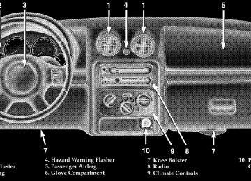
GLOVE COMPARTMENT To open the glove box, lift up on the latch.
136 UNDERSTANDING THE FEATURES OF YOUR VEHICLE
CUP HOLDERS In the center console there are two cup holders for the front seat passengers.
Smoker’s Package — If Equipped With the optional Smoker’s package, a removable ash tray is inserted into the front cup holder location. The rear passengers have access to a cup holder on each rear door trim panel.
Front Cup Holders
NOTE: The front cup holder insert is removable from the console, for cleaning.
Rear Cup Holders
UNDERSTANDING THE FEATURES OF YOUR VEHICLE 137
3. The swing gate may be opened or closed with the cargo cover in place.
CARGO AREA FEATURES
Cargo Light The cargo area light is activated by opening the swing gate, opening any door, or by rotating the dimmer control on the multi-function control lever to the extreme top position. If all doors are closed and only the swing gate is open, pushing on the cargo light lens surface will turn off all interior lights. Push on the lens surface a second time to restore the interior lights to normal operation. Retractable Cargo Area Cover — If Equipped To cover the cargo area: 1. Grasp the center portion of the cover flap. Pull it over the cargo area. 2. Insert the pins on the ends of the cover into the slots in the pillar trim cover.
138 UNDERSTANDING THE FEATURES OF YOUR VEHICLE
WARNING!
In an accident a cargo cover loose in the vehicle could cause injury. It could fly around in a sudden stop and strike someone in the vehicle. Do not store the cargo cover on the cargo floor or in the passenger compartment. Remove the cover from the vehicle when taken from its mounting. Do not store in the vehicle.
Cargo Tie-Down Hooks The tie-downs located on cargo area floor should be used to safely secure loads when vehicle is moving.
WARNING!
† Cargo tie-down hooks are not safe anchors for a child seat tether strap. In a sudden stop or colli- sion a hook could pull loose and allow the child seat to come loose. A child could be badly injured. Use only the anchors provided for child seat tethers. † The weight and position of cargo and passengers can change the vehicle center of gravity and vehicle handling. To avoid loss of control result- ing in personal injury, follow these guidelines for loading your vehicle:
† Always place cargo evenly on the cargo floor. Put heavier objects as low and as far forward as possible.
UNDERSTANDING THE FEATURES OF YOUR VEHICLE 139
† Place as much cargo as possible in front of the rear axle. Too much weight or improperly placed weight over or behind the rear axle can cause the rear of the vehicle to sway. † Do not pile luggage or cargo higher than the top of the seatback. This could impair visibility or become a dangerous projectile in a sudden stop or collision.
WARNING!
To help protect against personal injury, passengers should not be seated in the rear cargo area. The rear cargo space is intended for load carrying purposes only, not for passengers, who should sit in seats and use seat belts.
140 UNDERSTANDING THE FEATURES OF YOUR VEHICLE
Cargo Organizer — If Equipped This vehicle may be equipped with a cargo organizer that mounts on the floor behind the rear seat. Items may be placed on the flat surface or stored in the three storage compartments.
WARNING!
1. To raise the cargo organizer pull up on the handle and pull towards the rear of the vehicle.
positions.
† To avoid tipping, lock the shelf securely in all † Do not drive this vehicle with the liftgate open, or † Failure to follow these warnings could result in
use the shelf as a seat.
serious or fatal injury.
2. Place the rear corners of the cargo organizer into the supports located on the rear trim panel. Press down on the back of the cargo organizer to lock it into place.
UNDERSTANDING THE FEATURES OF YOUR VEHICLE 141
WARNING!
Do not load objects over 30 lbs (13.5 kg) in the upper position. Failure to follow this warning could cause the cargo organizer to collapse resulting in personal injury.
CAUTION!
Do not load objects over 100 lbs (45 kg) in the lower position. Failure to follow this could cause damage to the cargo organizer.
142 UNDERSTANDING THE FEATURES OF YOUR VEHICLE
To Open Storage Compartments 1. Pull up on the center opening of the cargo organizer.
Cargo Organizer Removal Loosen screw, then lift lever from each mount located on the floor of the rear cargo area, and remove the cargo organizer from the vehicle.
ROOF LUGGAGE RACK External racks do not increase the total load carrying capacity of the vehicle. Be sure that the total occupant and luggage load inside the vehicle, plus the load on the luggage rack, do not exceed the rated vehicle capacity as shown on the label attached to the drivers door shut face.
2. Lift up on the storage compartment dividers and lock into place.
UNDERSTANDING THE FEATURES OF YOUR VEHICLE 143
WARNING!
Cargo must be securely tied before driving your vehicle. Improperly secured loads can fly off the vehicle, particularly at high speeds, resulting in personal injury or property damage. Follow the roof rack “Cautions” when carrying cargo on your roof rack.
CAUTION!
† To avoid damage to the roof rack and vehicle, do not exceed the maximum roof rack load capacity of 150 lbs (68 kg) or 65 lbs (29.5 kg) on Renegade models. Always distribute heavy loads as evenly as possible and secure the load appropriately. † Long loads which extend over the windshield, such as wood panels or surfboards, should be secured to both the front and rear of the vehicle. † Place a blanket or other protection between the † Travel at reduced speeds and turn corners care- fully when carrying large or heavy loads on the roof rack. Wind forces, due to natural causes or nearby truck traffic, can add sudden upward loads. This is especially true on large flat loads and may result in damage to the cargo or your vehicle.
surface of the roof and the load.
UNDERSTANDING YOUR INSTRUMENT PANEL
CONTENTS
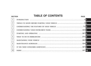
m Instrument Panel And Interior Controls . . . . . . . 149
m Instrument Cluster . . . . . . . . . . . . . . . . . . . . . . 150
m Instrument Cluster Description . . . . . . . . . . . . . 151
m Electronic Digital Clock . . . . . . . . . . . . . . . . . . 158
N Clock Setting Procedure . . . . . . . . . . . . . . . . . 158
m Radio General Information . . . . . . . . . . . . . . . . 158
N Radio Broadcast Signals . . . . . . . . . . . . . . . . . 158
N Two Types Of Signals . . . . . . . . . . . . . . . . . . 159
N Electrical Disturbances . . . . . . . . . . . . . . . . . . 159N AM Reception . . . . . . . . . . . . . . . . . . . . . . . 159
N FM Reception . . . . . . . . . . . . . . . . . . . . . . . . 159m Sales Code RBB—AM/FM Stereo Radio With
Cassette Tape Player And CD Changer Capability . . . . . . . . . . . . . . . . . . . . . . . . . . . . 160
N Operating Instructions . . . . . . . . . . . . . . . . . . 160
N Power Button . . . . . . . . . . . . . . . . . . . . . . . . 160
N Electronic Volume Control . . . . . . . . . . . . . . . 160
N Seek . . . . . . . . . . . . . . . . . . . . . . . . . . . . . . 161
N Tune . . . . . . . . . . . . . . . . . . . . . . . . . . . . . . 161146 UNDERSTANDING YOUR INSTRUMENT PANEL
N To Set The Push-Button Memory . . . . . . . . . . 161
N Balance . . . . . . . . . . . . . . . . . . . . . . . . . . . . 162
N Fade . . . . . . . . . . . . . . . . . . . . . . . . . . . . . . 162
N Bass And Treble Tone Control . . . . . . . . . . . . 162
N AM/FM Selection . . . . . . . . . . . . . . . . . . . . . 162
N Mode Button . . . . . . . . . . . . . . . . . . . . . . . . 162
N Cassette Player Features . . . . . . . . . . . . . . . . 162
N CD Changer Control Capability— If Equipped . . . . . . . . . . . . . . . . . . . . . . . 164
. . . . . . . . . . . . . . . . 166N Radio Display Messages
N CD Changer Control Capability
— If Equipped . . . . . . . . . . . . . . . . . . . . . . . 171
. . . . . . . . . . . . . . . . 173N Radio Display Messages
m Sales Code RBP—AM & FM Stereo Radio With Cassette Tape Player, CD Player, And Optional CD/DVD Changer Controls . . . . . . . . . . . . . . . 174
N Radio Operation . . . . . . . . . . . . . . . . . . . . . . 174
N Tape Player Operation . . . . . . . . . . . . . . . . . . 178
N CD Player Operation . . . . . . . . . . . . . . . . . . . 180
N CD/DVD Changer Operation— If Equipped . . . . . . . . . . . . . . . . . . . . . . . 182
m Sales Code RBK—AM/ FM Stereo Radio With
CD Player And CD Changer Controls . . . . . . . . 167
N Radio Operation . . . . . . . . . . . . . . . . . . . . . . 167
N CD Player Operation . . . . . . . . . . . . . . . . . . . 169m Sales Code RBQ—AM/FM Stereo Radio With
. . . . . . . . . . . . . . . . . . . . 183
6 - Disc CD Changer N Radio Operation . . . . . . . . . . . . . . . . . . . . . . 184
N CD Player Operation . . . . . . . . . . . . . . . . . . . 186m Satellite Radio — If Equipped . . . . . . . . . . . . . . 190
N System Activation . . . . . . . . . . . . . . . . . . . . . 190
N Electronic Serial Number/Sirius IdentificationNumber (ENS/SID) . . . . . . . . . . . . . . . . . . . . 190
N Selecting Satellite Mode In RBB And RBK
Radios . . . . . . . . . . . . . . . . . . . . . . . . . . . . . 191
N Selecting Satellite Mode In RBP, RBU, RAZ,
And RBQ Radios
. . . . . . . . . . . . . . . . . . . . . 191
N Selecting a Channel . . . . . . . . . . . . . . . . . . . . 192
N Storing And Selecting Pre-Set Channels . . . . . . 192
N Using The PTY (Program Type) Button(If Equipped)
. . . . . . . . . . . . . . . . . . . . . . . . 192
N PTY Button 9Scan9 . . . . . . . . . . . . . . . . . . . . . 193
N PTY Button 9Seek9 . . . . . . . . . . . . . . . . . . . . . 193UNDERSTANDING YOUR INSTRUMENT PANEL 147
N Satellite Antenna . . . . . . . . . . . . . . . . . . . . . . 193
N Reception Quality . . . . . . . . . . . . . . . . . . . . . 193
m Remote Sound System Controls — If Equipped . . 194
N Radio Operation . . . . . . . . . . . . . . . . . . . . . . 195
N Tape Player . . . . . . . . . . . . . . . . . . . . . . . . . 195
N CD Player — Single Disc In Radio . . . . . . . . . 195
N CD Player — 6 Disc In Cargo Area . . . . . . . . . 196
m Cassette Tape And Player Maintenance . . . . . . . 196
m CD/DVD Disc Maintenance . . . . . . . . . . . . . . . 197
m Radio Operation And Cellular Phones . . . . . . . . 198
m Climate Controls . . . . . . . . . . . . . . . . . . . . . . . 198
N Heater . . . . . . . . . . . . . . . . . . . . . . . . . . . . . 198
N Air Conditioning . . . . . . . . . . . . . . . . . . . . . 200148 UNDERSTANDING YOUR INSTRUMENT PANEL
N Operating Tips . . . . . . . . . . . . . . . . . . . . . . . 202
m Rear Window Features . . . . . . . . . . . . . . . . . . . 203N Rear Window Wiper/Washer . . . . . . . . . . . . . 203
N Rear Window Defroster . . . . . . . . . . . . . . . . . 204INSTRUMENT PANEL AND INTERIOR CONTROLS
UNDERSTANDING YOUR INSTRUMENT PANEL 149
150 UNDERSTANDING YOUR INSTRUMENT PANEL
INSTRUMENT CLUSTER
INSTRUMENT CLUSTER DESCRIPTION
1. Tachometer Indicates the permissible engine revolutions-per-minute for each gear range. Before reaching the red area, ease up on the accelerator to prevent engine damage. 2. Turn Signal Indicator Light
The arrows will flash in unison with the exterior turn signals, when using the multi-function control lever. A chime will sound if the turn signals are left on continuously for 2 miles (3 km) until they are deacti- vated. 3. High Beam Indicator Light
This light shows that the headlights are on high beam. Pull the multi-function control lever to- wards the steering wheel to switch the headlights from high to low beam.
UNDERSTANDING YOUR INSTRUMENT PANEL 151
4. Speedometer Indicates vehicle speed. 5. Tire Pressure Monitor Warning Light — If Equipped This light will turn on when there is a low tire pressure condition. The light will also turn on if a problem exist with any tire sensor. The light will remain on until the tire pressure is prop-
erly set or the problem with the sensor is corrected. This light will turn on momentarily as a bulb check when the engine is started. When the “Tire Pressure Monitor Warning Light” is lit, one or more of your tires is significantly under-inflated. You should stop and check your tires as soon as possible, and inflate them to the proper pressure as indicated on the vehicle’s tire information placard. Driving on a significantly under-inflated tire causes the tire to over- heat and can lead to tire failure. Under-inflation also reduces fuel efficiency and tire tread life, and may affect
152 UNDERSTANDING YOUR INSTRUMENT PANEL
the vehicle’s handling and stopping ability. Each tire, including the spare, should be checked monthly when cold and set to the recommended inflation pressure as specified on the vehicle placard. 6. 4LO Mode Indicator Light — If Equipped
This light alerts the driver that the vehicle is in the 4 LO four–wheel drive mode. The front and rear driveshafts are mechanically locked to- gether forcing the front and rear wheels to
rotate at the same speed. 7. Fog Light Indicator Light — If Equipped
This light shows when the front fog lights are on.
8. Malfunction Indicator Light
This light is part of an onboard diagnostic system called OBD II which monitors engine and auto- matic transmission control systems. This light will illuminate when the ignition is in the ON position
before engine start. If the bulb does not come on when turning the ignition key from OFF to ON, have the condition checked promptly. Certain conditions such has a loose or missing gas cap, poor fuel quality, etc. may illuminate the light after engine start. The vehicle should be serviced if the light stays on through several typical driving cycles. In most situations, the vehicle will drive normally and will not require towing. When the engine is running, the “Malfunction Indicator Light” may flash to alert of serious conditions that could lead to immediate loss of power or severe catalytic converter damage. The vehicle should be serviced as soon as possible if this occurs. 9. Anti-Lock Warning Light (ABS) — If Equipped
This light monitors the Anti-Lock Brake System (ABS) described elsewhere in this manual. This
light will come on when the ignition switch is turned to the ON position and may stay on for as long as three seconds. If the light comes back on immediately or comes on during driving, it indicates that the Anti-Lock portion of the brake system is not functioning and that service is required, however, the conventional brake system will continue to operate normally provided that the BRAKE warning light is not on. Also, a chime will sound if the light comes back on. If the ABS light is on, the brake system should be serviced as soon as possible to restore the benefit of Anti-Lock Brakes. The operation of the ABS light can be checked by turning the ignition switch from the OFF position to the ON position. The light should illuminate for approximately two seconds. The light should then turn off unless the
UNDERSTANDING YOUR INSTRUMENT PANEL 153
parking brake is applied or a brake fault is detected. If the light does not illuminate, have the light inspected by an authorized dealer. 10. Charging System Warning Light
This light shows the status of the electrical charg- ing system. The light should come on for three seconds when the ignition is first turned ON. If the light comes back on immediately or comes on while driving, it means that there is a problem with the charging system or the battery is low. Also, a chime will sound if the light comes back on. See your authorized dealer immediately. 11. Temperature Gage
Indicates engine coolant temperature. Any read- ing within the normal range indicates that the cooling system is operating satisfactorily.
The gage pointer will likely indicate a higher temperature (above center scale) when driving in hot weather, up mountain grades, in heavy stop and go traffic, or when
154 UNDERSTANDING YOUR INSTRUMENT PANEL
towing a trailer. It should not be allowed to exceed the upper limits of the normal operating range. If the pointer rises to the red zone (five chimes will occur), pull over and stop the vehicle. Do not turn the engine off. Idle the vehicle with the air conditioning turned off, until the pointer drops back into the normal range. If the engine remains in the high range, turn the engine off and call for service. 12. Reset Button Press this button to toggle between the odometer and trip odometer display. When in the trip odometer mode, holding the button in resets the trip odometer. Also, pressing the “Reset” button will clear out any warning messages in the odometer display. 13. Odometer/Trip Odometer A vacuum fluorescent display indicates the total distance the vehicle has been driven. Also, the cluster will display, replacing the odometer/trip odometer, vehicle warning
messages such as: door/gate/glass ajar and low washer fluid. See appropriate sections for more information. If vehicle is equipped with the optional Elec- NOTE: tronic Vehicle Information Center (EVIC) in the overhead console, all warnings including “door”, “GATE”, “GLASS”, and “LOWASH” will only be displayed in the EVIC display (not in the instrument cluster). For addi- tional information, refer to “Overhead Console — If Equipped” in Section 3. U.S. federal regulations require that upon transfer of vehicle ownership, the seller certify to the purchaser the correct mileage that the vehicle has been driven. There- fore, if the odometer reading is changed during repair or replacement, be sure to keep a record of the reading before and after the service so that the correct mileage can be determined.
14. Cruise Indicator Light
This indicator lights when the speed control system is turned ON. 15. Oil Pressure Warning Light
Shows low engine oil pressure. The light will come on and remain on when the ignition switch is turned from the OFF to the ON position, and the light will turn off after the engine is started. If the bulb does not come on, have the system checked by your autho- rized dealer. If the warning light comes on and remains on while driving, stop the vehicle and shut off the engine. DO NOT OPERATE THE VEHICLE UNTIL THE CAUSE IS CORRECTED. Also, a single chime will sound. 16. Transmission Temperature Warning Light
This light indicates that there is excessive trans- mission fluid temperature that might occur with severe usage such as trailer towing or snow plowing. If
UNDERSTANDING YOUR INSTRUMENT PANEL 155
this light comes on, stop the vehicle and run the engine at idle or faster, with the transmission in N (Neutral) until the light goes off. 17. Part Time Indicator Light — If Equipped
This light alerts the driver that the vehicle is in the PART TIME four–wheel drive high range mode, and the front and rear driveshafts are mechanically locked together forcing the front and rear wheels to rotate at the same speed. 18. Brake Warning Light
This light monitors various brake functions, including brake fluid level and parking brake application. If the light comes on, it may indi- cate that the parking brake is applied, or there is a low brake fluid level. On vehicles equipped with Anti-Lock brakes (ABS), it may also indicate an ABS malfunction that could lead to reduced braking perfor- mance.
156 UNDERSTANDING YOUR INSTRUMENT PANEL
WARNING!
Driving a vehicle with the BRAKE warning light on is dangerous. A significant decrease in braking per- formance or vehicle stability during braking may occur. It will take you longer to stop the vehicle or will make your vehicle harder to control. You could have an accident. Have the vehicle checked immedi- ately.
The operation of the BRAKE warning light can be checked by turning the ignition switch from the OFF position to the ON position. The light should illuminate for approximately two seconds. The light should then turn off unless the parking brake is applied or a brake fault is detected. If the light does not illuminate, have the light inspected by an authorized dealer.
Also, the light will come on when the parking brake is applied with the ignition switch in the ON position. NOTE: This light shows only that the parking brake is applied. It does not show the degree of brake application. If the parking brake is off and the light remains on, have the brake system inspected as soon as possible. 19. Full Time Indicator Light — If Equipped
This light alerts the driver that the vehicle is in the FULL TIME four–wheel drive mode, and employs the inter-axle differential which al- lows the front and rear wheels to rotate at
different speeds. 20. Security Alarm System Indicator Light — If Equipped This light will flash rapidly for approximately 16 seconds after all of the doors are locked and closed to signal that
the system is arming. After the alarm successfully arms, the light will flash at a slower rate to indicate the alarm is set. 21. Fuel Gage When the ignition key is in the ON position, the pointer will show the level of fuel remaining in the fuel tank. A small arrow indicates the side of the vehicle where the filler cap (gas cap) is located. 22. Sentry Key Indicator Light — If Equipped
Refer to “Sentry Key Immobilizer System” in Section 2 of this manual for more information.
23. Low Fuel Warning Light
When the fuel level reaches approximately 2.7 U.S. Gallons (10L) this light will come on and remain on until fuel is added. The “Low Fuel Warning Light” may turn on and off again, especially during and after
UNDERSTANDING YOUR INSTRUMENT PANEL 157
hard braking, accelerations, or turns. This occurs due to the shifting of the fuel in the tank. Also, a single chime will sound. 24. Airbag Warning Light
This indicator lights and remains lit for 6 to 8
seconds when the ignition is first turned on. If the light doesn’t come on, stays on, or comes on while driving, have the airbag system checked by an autho- rized dealer. 25. O/D (Overdrive) Off Indicator Lightilluminate when the O/D OFF This light will button has been selected. The O/D OFF button is
located on the gear shift lever. 26. Seat Belt Indicator Light
When the ignition switch is first turned ON, this light will turn on for 5 to 8 seconds as a bulb check. During the bulb check, if the driver’s seat belt is unbuckled, a chime will sound. After the bulb check or
158 UNDERSTANDING YOUR INSTRUMENT PANEL
when driving, if the driver seat belt remains unbuckled, the Seat Belt Warning Light will flash or remain on continuously. Refer to 9Enhanced Driver Seat Belt Re- minder System (BeltAlert™)9 in the Occupant Restraints section for more information. 27. Light Bar Indicator Light — If Equipped
This light indicates when the light bar lamps are on.
ELECTRONIC DIGITAL CLOCK
The clock and radio each use the display panel built into the radio. A digital readout shows the time in hours and minutes whenever the ignition switch is in the ON or ACC position and the time button is pressed. When the ignition switch is in the OFF position, or when the radio frequency is being displayed, time keeping is accurately maintained.
Clock Setting Procedure
1. Turn the ignition switch to the ON or ACC position and press the time button. Using the tip of a ballpoint pen or similar object, press either the hour (H) or minute (M) buttons on the radio. 2. Press the H button to set hours or the M button to set minutes. The time setting will increase each time you press a button.
RADIO GENERAL INFORMATION
Radio Broadcast Signals Your new radio will provide excellent reception under most operating conditions. Like any system, however, car radios have performance limitations, due to mobile op- eration and natural phenomena, which might lead you to believe your sound system is malfunctioning. To help
UNDERSTANDING YOUR INSTRUMENT PANEL 159
AM Reception AM sound is based on wave amplitude, so AM reception can be disrupted by such things as lightning, power lines and neon signs. FM Reception Because FM transmission is based on frequency varia- tions, interference that consists of amplitude variations can be filtered out, leaving the reception relatively clear, which is the major feature of FM radio.
you understand and save you concern about these “ap- parent” malfunctions, you must understand a point or two about the transmission and reception of radio sig- nals. Two Types of Signals There are two basic types of radio signals... AM or Amplitude Modulation, in which the transmitted sound causes the amplitude, or height, of the radio waves to vary... and FM or Frequency Modulation, in which the frequency of the wave is varied to carry the sound. Electrical Disturbances Radio waves may pick up electrical disturbances during transmission. They mainly affect the wave amplitude, and thus remain a part of the AM reception. They interfere very little with the frequency variations that carry the FM signal.
160 UNDERSTANDING YOUR INSTRUMENT PANEL
SALES CODE RBB—AM/FM STEREO RADIO WITH CASSETTE TAPE PLAYER AND CD CHANGER CAPABILITY
Operating Instructions
NOTE: Power to operate the radio is supplied through the ignition switch. It must be in the ON or ACC position to operate the radio.
NOTE: When first learning the control functions, the user should set the controls as shown in the following list. Tone Controls…As illustrated. Speaker Control…Centered. Power Button The volume control/power button pops out when pressed, this turns the sound system ON in the mode last used. Pushing the button back in turns the sound system OFF. Electronic Volume Control The electronic volume control turns continuously (360
degrees) in either direction without stopping. Turning the volume control to the right increases the volume and to the left decreases it. When the audio system is turned on, the sound will be set at the same volume level as last played.For your convenience, the volume can be turned down, but not up, when the audio system is off and the ignition is ON. Seek Press and release the SEEK button to search for the next station in either the AM or FM mode. Press the top of the button to seek up and the bottom to seek down. The radio will remain tuned to the new station until you make another selection. Holding the button will bypass stations without stopping until you release it. Tune Press the TUNE control up or down to increase or decrease the frequency. If the button is pushed and held, the radio will continue to tune until the button is released. The frequency will be displayed and continu- ously updated while the button is pushed.
UNDERSTANDING YOUR INSTRUMENT PANEL 161
To Set The Push-Button Memory When you are receiving a station that you wish to commit to push-button memory, press the SET button. The symbol SET 1 will now show in the display window. Select the “1–5” button you wish to lock onto this station and press and release that button. If a button is not selected within 5 seconds after pressing the SET button, the station will continue to play but will not be locked into push-button memory. You may add a second station to each push-button by repeating the above procedure with this exception: Press the SET button twice and SET 2 will show in the display window. Each button can be set for SET 1 and SET 2 in both AM and FM. This allows a total of 10 AM and 10 FM stations to be locked into push-button memory. The stations stored in SET 2 memory can be selected by pressing the push-button twice.
162 UNDERSTANDING YOUR INSTRUMENT PANEL
Every time a preset button is used a corresponding button number will be displayed. Balance The balance control adjusts the left-to-right speaker bal- ance. Press the BAL button in and it will pop out. Adjust the balance and push the button back in. Fade The fade control provides for balance between the front and rear speakers. Press the FADE button in and it will pop out. Adjust the balance and push the button back in. Bass and Treble Tone Control The tone controls consist of 2 separate bands. The bass band is on the left, and the treble band is on the right. Each band is adjusted by a slider control with a detent at the mid-position. Moving the control up or down in- creases or decreases amplification of that band. The mid position provides a balanced output.
AM/FM Selection Press the AM/FM button to change from AM to FM. The operating mode will be displayed next to the station frequency. The display will show ST when a stereo station is received in the FM mode. Mode Button Press the MODE button to select between the cassette tape player, CD changer, or the Satellite Radio (if equipped). When the Satellite Radio (if equipped) is selected “SA” will appear in your radio display. A CD or tape may remain in the player while in the Satellite or radio mode. Cassette Player Features With ignition OFF and the sound system OFF, you can eject the tape cassette by pushing the EJECT button.
You can turn the tape player ON by inserting a cassette or activating the MODE button (with a cassette in the radio), but only when the ignition and radio are on. Each time a cassette is inserted the tape player will begin playing on the side of the cassette that is facing up in the player. Music Search Pressing the SEEK button while playing a tape will start the Music Search mode. Press the SEEK button up for the next selection on the tape and down to return to the beginning of the current selection, or return to the beginning of the previous selection if the tape is within the first 5 seconds of the current selection. The SEEK symbol appears on the display when Music Search is in operation. Music Search shuts off automati- cally when a selection has been located.
UNDERSTANDING YOUR INSTRUMENT PANEL 163
Selective Music Search Press the SEEK button up or down to move the track number to skip forward or backward 1 to 7 selections. Press the SEEK button once to move 1 selection, twice to move 2 selections, etc. Fast Forward And Rewind Buttons Pressing the TUNE button up or down momentarily activates Fast Forward or Rewind and makes the direc- tional arrows appear on the display. To stop Fast Forward or Rewind, press the TUNE button again. Time Button Press the time button to toggle between station frequency and time of day. Pressing this button while playing a cassette tape will change the side of the tape being played.
164 UNDERSTANDING YOUR INSTRUMENT PANEL
NR (Noise Reduction) Pushing the Number 2 Pre-set button when a tape is playing deactivates the Dolby Noise Reduction System*. When Dolby is ON, the NR symbol appears on the display. Each time a tape is inserted the Dolby will turn ON. * “Dolby” noise reduction manufactured under license from Dolby Laboratories Licensing Corporation. Dolby and the double-D symbol are trademarks of Dolby Labo- ratories Licensing Corporation. CD Changer Control Capability — If Equipped This radio is compatible with a remote mounted CD