- 2009 Jeep Liberty Owners Manuals
- Jeep Liberty Owners Manuals
- 2011 Jeep Liberty Owners Manuals
- Jeep Liberty Owners Manuals
- 2010 Jeep Liberty Owners Manuals
- Jeep Liberty Owners Manuals
- 2007 Jeep Liberty Owners Manuals
- Jeep Liberty Owners Manuals
- 2008 Jeep Liberty Owners Manuals
- Jeep Liberty Owners Manuals
- 2005 Jeep Liberty Owners Manuals
- Jeep Liberty Owners Manuals
- 2004 Jeep Liberty Owners Manuals
- Jeep Liberty Owners Manuals
- Download PDF Manual
-
when the driver is not in the vehicle.
Shift Positions For additional information on the appropriate use of each transfer case mode position see the information below: 2H Rear Wheel Drive High Range - Normal street and highway driving. Dry hard surfaced roads. 4H 4-Wheel-Drive High Range - Locks the front and rear driveshafts together. Forces the front and rear wheels to rotate at the same speed. Additional traction for loose, slippery road surfaces only. Neutral - Disengages both the front and rear driveshafts from the powertrain. To be used for flat towing behind another vehicle. Refer to “Recreational Towing” in Sec- tion 5 for more information.
4L 4-Wheel-Drive Low Range - Low speed 4 wheel drive. Locks the front and rear driveshafts together. Forces the front and rear wheels to rotate at the same speed. Additional traction and maximum pulling power for loose, slippery road surfaces only. Do not exceed 25 mph (40 km/h). (Allows engine starting without depressing the clutch pedal on vehicles equipped with manual transmission. Refer to “Starting Procedures — Manual Transmission (4WD Models Only)” in this section. Shifting Procedure
2H to 4H or 4H to 2H Shifting between 2H and 4H can be made with the vehicle in motion up to 55 mph (88 km/h). The transfer case will engage/disengage faster if you momentarily release the accelerator pedal after completing the shift. Apply a constant force when shifting the transfer case lever.
STARTING AND OPERATING 225
4H to 4L or 4L to 4H With the vehicle rolling at 2 to 3 mph (3 to 5 km/h), shift an automatic transmission to N (Neutral) or depress the clutch on a manual transmission. While the vehicle is coasting at 2 to 3 mph (3 to 5 km/h), shift the transfer case lever firmly to the desired position. Do not pause in transfer case N (Neutral). NOTE: To shift from 4H to 4L, the shift lever should pushed away from the driver, and then rearward into 4L. In 4H, there is a neutral stop to prevent shifting into N (Neutral) by accident. NOTE: Pausing in transfer case N (Neutral) in vehicles equipped with an automatic transmission may require shutting the engine OFF to avoid gear clash while completing the shift. If difficulty occurs, shift automatic transmission to N (Neutral), hold foot on brake, and turn engine OFF. Make shift to the desired mode.
226 STARTING AND OPERATING
NOTE: Shifting into or out of 4L is possible with the vehicle completely stopped, however difficulty may oc- cur due to the mating clutch teeth not being properly aligned. Several attempts may be required for clutch teeth alignment and shift completion to occur. The pre- ferred method is with the vehicle rolling 2 to 3 mph (3 to 5 km/h). Avoid attempting to engage or disengage 4L with the vehicle moving faster than 2 to 3 mph (3 to 5
km/h). Selec-TracT Operating Information/Precautions — If Equipped The Selec-Tract transfer case provides 5 mode positions - normal 2-wheel drive mode, part-time 4-wheel drive high range, full-time 4-wheel drive high range, neutral, and 4-wheel drive low range. This transfer case is equipped with an inter-axle differ- ential which allows driving the vehicle in the 4 FULL TIME position at all times on any given road surfaceincluding dry hard surfaced roads. The 4 FULL TIME mode allows the front and rear wheels to rotate at different speeds which eliminates driveline binding and component wear that is normally associated with driving the vehicle in the 4 PART TIME position on dry hard surfaced roads. This feature provides the safety, security, and convenience of operating in 4–wheel drive at all times regardless of road conditions. When additional traction is required the 4 PART TIME and 4LO positions can be used to lock the front and rear driveshafts together through the transfer case inter-axle differential and force the front and rear driveshafts to rotate at the same speed. This is accomplished by simply moving the shift lever to these positions. The 4 PART TIME and 4LO positions are intended for loose, slippery road surfaces only. Driving in the 4 PART TIME and 4LO positions on dry hard surfaced roads may cause in- creased tire wear and damage to driveline components.
The PART TIME indicator light, located on the instru- ment cluster, illuminates when the transfer case is shifted to the 4 PART TIME position. The FULL TIME indicator light, located on the instru- ment cluster, illuminates when the transfer case is shifted to the 4 FULL TIME position. The 4LO MODE indicator light, located on the instru- ment cluster, illuminates when the transfer case is shifted to the 4LO position. There is no light for the 2WD, or N (Neutral) positions.
STARTING AND OPERATING 227
CAUTION!
† Do not attempt to make a shift while only the front or rear wheels are spinning. The Selec-Trac transfer case is not equipped with a synchronizer and therefore the front and rear driveshaft speeds must be equal for the shift to take place. Shifting while only the front or rear wheels are spinning can cause damage to the transfer case. † When operating your vehicle in 4LO, the engine speed is approximately three times that of the 2WD, 4 PART TIME, or 4 FULL TIME positions at a given road speed. Take care not to overspeed the engine and do not exceed 25 mph (40 km/h).
228 STARTING AND OPERATING
Proper operation of 4-wheel drive vehicles depends on tires of equal size, type, and circumference on each wheel. Any difference will adversely affect shifting and can cause damage to the transfer case.
WARNING!
† Because 4-wheel drive provides improved trac- tion, there is a tendency to exceed safe turning and stopping speeds. Do not go faster than road con- ditions permit. † You or others could be injured if you leave the vehicle unattended with the transfer case in the Neutral (N) position without first fully engaging the parking brake. The transfer case Neutral (N) position disengages both the front and rear drive- shafts from the powertrain and will allow the vehicle to move regardless of the transmission position. The parking brake should always be applied when the driver is not in the vehicle.
Shift Positions For additional information on the appropriate use of each transfer case mode position see the information below: 2WD Rear Wheel Drive High Range - Normal street and highway driving. Dry hard surfaced roads. 4 PART TIME Part Time 4–Wheel Drive High Range - Locks the transfer case inter-axle differential. Forces the front and rear wheels to rotate at the same speed. Additional traction for loose, slippery road surfaces only. 4 FULL TIME Full Time 4-Wheel Drive High Range - Employs an inter-axle differential. This allows front and rear wheels to rotate at different speeds, on all road surfaces.
STARTING AND OPERATING 229
Neutral - Disengages both the front and rear driveshafts from the powertrain. To be used for flat towing behind another vehicle. Refer to “Recreational Towing” in Sec- tion 5 for more information. 4LO Part Time 4–Wheel Drive Low Range - Low speed 4–wheel drive. Locks the transfer case inter-axle differ- ential. Forces the front and rear wheels to rotate at the same speed. Additional traction and maximum pulling power for loose, slippery road surfaces only. Do not exceed 25 mph (40 km/h).
230 STARTING AND OPERATING
Shifting Procedure
2WD to 4 PART TIME or 4 PART TIME to 2WD Shifting between 2WD and 4 PART TIME can be made with the vehicle stopped or in motion. If the vehicle is in motion, shifts can be made up to 55 mph (88 km/h). With the vehicle in motion two momentary releases of the accelerator pedal may be required after shifting. This will induce a torque interrupt and allow full engagement of the newly selected position. With the vehicle stationary it may be necessary to shift the automatic transmission from D (Drive) to R (Reverse) and back to D (Drive) after shifting. This will allow full engagement of the newly selected position. Apply a constant force when shifting the transfer case lever. 4 PART TIME to 4 FULL TIME or 4 FULL TIME to 4 PART TIME Shifting between 4 PART TIME and 4 FULL TIME can be made with the vehicle stopped or in motion. If the vehicle
is in motion shifts can be made up to 55 mph (88 km/h). With the vehicle in motion two momentary releases of the accelerator pedal may be required after shifting. This will induce a torque interrupt and allow full engagement of the newly selected position. With the vehicle stationary it may be necessary to shift the automatic transmission from D (Drive) to R (Reverse) and back to D (Drive) after shifting. This will allow full engagement of the newly selected position. Apply a constant force when shifting the transfer case lever. 4 FULL TIME to 4 LO or 4 LO to 4 FULL TIME With the vehicle rolling at 2 to 3 mph (3 to 5 km/h), shift an automatic transmission to N (Neutral). While the vehicle is coasting at 2 to 3 mph (3 to 5 km/h), shift the transfer case lever firmly to the desired position. Do not pause in transfer case N (Neutral). NOTE: To shift from 4 FULL TIME to 4LO, the shift lever should be pushed away from the driver, and then
rearward into 4LO. In 4 FULL TIME, there is a neutral stop to prevent shifting into N (Neutral) by accident. NOTE: Pausing in transfer case N (Neutral) in vehicles equipped with an automatic transmission may require shutting the engine OFF to avoid gear clash while completing the shift. If difficulty occurs, shift transmis- sion to N (Neutral), hold foot on brake, and turn engine OFF. Make shift to desired mode. NOTE: Shifting into or out of 4LO is possible with the vehicle completely stopped, however difficulty may oc- cur due to the mating clutch teeth not being properly aligned. Several attempts may be required for clutch teeth alignment and shift completion to occur. The pre- ferred method is with the vehicle rolling 2 to 3 mph (3 to 5 km/h). Avoid attempting to engage or disengage 4LO with the vehicle moving faster than 2 to 3 mph (3 to 5
km/h).STARTING AND OPERATING 231
TRAC-LOK™ REAR AXLE — IF EQUIPPED The optional Trac-Lok™ rear axle provides a constant driving force to both rear wheels and reduces wheel spin caused by the loss of traction at one driving wheel. If traction differs between the two rear wheels, the differ- ential automatically proportions the usable torque by providing more torque to the wheel that has traction. Trac-Lok™ is especially helpful during slippery driving conditions. With both rear wheels on a slippery surface, a slight application of the accelerator will supply maxi- mum traction. When starting with only one rear wheel on an excessively slippery surface, slight application of the parking brake may be necessary to gain maximum trac- tion.
232 STARTING AND OPERATING
WARNING!
On vehicles equipped with a limited-slip differen- tial, never run the engine with one rear wheel off the ground. The vehicle may drive through the rear wheel remaining on the ground and cause you to lose control of your vehicle.
PARKING BRAKE To set the parking brake, pull the lever up as firmly as possible. When the parking brake is applied with the ignition ON, the “Brake Warning Light” in the instru- ment cluster will light. NOTE: The instrument cluster “Brake Warning Light” indicates only that the parking brake is applied. You must be sure the parking brake is fully applied before leaving the vehicle.
To release the parking brake, pull up slightly, press the center button, then lower the lever completely.
Before leaving the vehicle parked on a hill, you must make sure the parking brake is fully applied and place the gear selector in the P (Park) position. Make certain the transfer case is in gear. Failure to do so may cause the vehicle to roll and cause damage or injury. When parking on a hill, it is important to set the parking brake before placing the gear selector in P (Park), other- wise the load on the transmission locking mechanism may make it difficult to move the selector out of P (Park).
STARTING AND OPERATING 233
WARNING!
† Leaving children unattended in a vehicle is dan- gerous for a number of reasons. A child or others could be injured. Children should be warned not to touch the parking brake or the gear selector lever. Don’t leave the keys in the ignition. A child could operate power windows, other controls, or move the vehicle. † Do not leave children or animals inside parked vehicles in hot weather. Interior heat build up may cause serious injury or death.
Be sure the parking brake is fully disengaged before driving. Failure to do so can lead to brake failure. NOTE: Parking brake adjustment and maintenance should be performed by your authorized dealer.
234 STARTING AND OPERATING
ANTI-LOCK BRAKE SYSTEM — IF EQUIPPED The Anti-Lock Brake System is designed to aid the driver in maintaining vehicle control under adverse braking conditions. The system operates with a separate com- puter to modulate hydraulic pressure to prevent wheel lock-up and help avoid skidding on slippery surfaces. All vehicle wheels and tires must be the same size and type and tires must be properly inflated to produce accurate signals for the computer.
WARNING!
Significant over or under-inflation of tires, or mixing sizes of tires or wheels on the vehicle can lead to loss of braking effectiveness.
The Anti-Lock Brake System conducts a low speed self- test at about 12 mph (20 km/h). If for any reason, your foot is on the brake when the vehicle reaches 12 mph (20
km/h), this check will be delayed until 25 mph (40
km/h). The Anti-Lock Brake System pump motor runs during the self-test and during an ABS stop to provide the regulated hydraulic pressure. The motor pump makes a low humming noise during operation, this is normal. During off-road use, loss of traction can temporarily defeat the system and cause the warning light to illumi- nate. Turn the ignition OFF and ON again to restore Anti-Lock Brake System function.WARNING!
WARNING!
STARTING AND OPERATING 235
Pumping of the Anti-Lock Brakes will diminish their effectiveness and may lead to an accident. Pumping makes the stopping distance longer. Just press firmly on your brake pedal when you need to slow down or stop.
† Anti-lock system (ABS) cannot prevent the natu- ral laws of physics from acting on the vehicle, nor can it increase braking or steering efficiency be- yond that afforded by the condition of the vehicle brakes and tires or the traction afforded.
† The ABS cannot prevent accidents,
including those resulting from excessive speed in turns, following another vehicle too closely, or hydro- planing. Only a safe, attentive, and skillful driver can prevent accidents. † The capabilities of an ABS equipped vehicle must never be exploited in a reckless or dangerous manner which could jeopardize the user’s safety or the safety of others.
236 STARTING AND OPERATING
CAUTION!
The Anti-Lock Brake System is subject to possible detrimental effects of electronic interference caused by improperly installed aftermarket radios or tele- phones.
NOTE: During severe braking conditions, a pulsing sensation may occur and a clicking noise will be heard. This is normal, the Anti-Lock Brake System is functioning.
indicating that
ON-ROAD DRIVING TIPS Utility vehicles have higher ground clearance and a narrower track to make them capable of performing in a wide variety of off-road applications. Specific design characteristics give them a higher center of gravity than ordinary cars.
An advantage of the higher ground clearance is a better view of the road, allowing you to anticipate problems. They are not designed for cornering at the same speeds as conventional 2-wheel drive vehicles any more than low- slung sports cars are designed to perform satisfactorily in off-road conditions. If at all possible, avoid sharp turns or abrupt maneuvers. As with other vehicles of this type, failure to operate this vehicle correctly may result in loss of control or vehicle rollover.
OFF-ROAD DRIVING TIPS
When To Use 4L or 4 LO (Low) Range When driving off-road, shift to 4L or 4 LO for additional traction in moving forward or descending a hill, for low-speed pulling power or to improve handling and control on slippery or difficult terrain. Also use 4L or 4
LO range on the road in rain, ice, snow, mud or sand to get heavy loads rolling, or whenever “High” range four-wheel drive traction is insufficient.In Snow, Mud and Sand In heavy snow, when pulling a load, or for additional control at slower speeds, shift the transmission to a low gear and shift the transfer case to 4L or 4 LO if necessary. Don’t shift to a lower gear than necessary to maintain headway. Over-revving the engine can spin the wheels and traction will be lost. Do not downshift on icy or slippery roads, because engine braking may cause skidding and loss of control. Hill Climbing Before climbing a steep hill, shift the transmission to a lower gear and shift the transfer case to 4L or 4 LO. Use first gear and 4L or 4 LO for very steep hills.
STARTING AND OPERATING 237
If you stall or begin to lose headway while climbing a steep hill, allow your vehicle to come to a stop and immediately apply the brakes. Restart the engine and shift to R (Reverse). Back slowly down the hill allowing the compression braking of the engine and transmission to help regulate your speed. If the brakes are required to control vehicle speed, apply them lightly and avoid locking or skidding the tires.
WARNING!
If the engine stalls or you lose headway or cannot make it to the top of a steep hill or grade, never attempt to turn around. To do so may result in tipping and rolling the vehicle. Always back care- fully straight down a hill in R (Reverse) gear. Never back down a hill in N (Neutral) using only the brake.
238 STARTING AND OPERATING
Remember, never drive diagonally across a hill-always drive straight up or down. If the wheels start to slip as you approach the crest of a hill, ease off the accelerator and maintain headway by turning the front wheels sharply left and right. This will provide fresh “bite” into the surface and will usually provide traction to complete the climb. Traction Downhill Shift the transmission into a low gear and the transfer case to 4L or 4 LO range. Let the vehicle go slowly down the hill with all four wheels turning against engine compression drag. This will permit you to control the vehicle speed and direction. When descending mountains or hills, repeated braking can cause brake fade with loss of braking control. Avoid repeated heavy braking by downshifting the transmis- sion whenever possible.
After Driving Off-Road Off-road operation puts more stress on your vehicle than does most on-highway driving. After going off-road it is always a good idea to check for damage. That way you can get any problems taken care of right away and have your vehicle ready when you need it. † Completely inspect the underbody of your vehicle. Check tires, body structure, steering, suspension, and exhaust system for damage. † Check threaded fasteners for looseness, particularly on the chassis, drivetrain components, steering, and sus- pension. Retighten them, if required, and torque to the values specified in the Service Manual. † Check for accumulations of plants or brush. These things could be a fire hazard. They might hide damage to fuel lines, brake hoses, axle pinion seals, and propeller shafts.
† After extended operation in mud, sand, water, or similar dirty conditions, have brake rotors, wheels, brake linings, and axle yokes inspected and cleaned as soon as possible.
WARNING!
Abrasive material in any part of the brakes may cause excessive wear or unpredictable braking. You might not have full braking power when you need it to prevent an accident. If you have been operating your vehicle in dirty conditions, get your brakes checked and cleaned as necessary. † If you experience unusual vibration after driving in mud, slush or similar conditions, check the wheels for impacted material. Impacted material can cause a wheel imbalance and freeing the wheels of it will correct the situation.
STARTING AND OPERATING 239
TIRE SAFETY INFORMATION
Tire Markings
NOTE: † P(Passenger)-Metric tire sizing is based on U.S. design standards. P-Metric tires have the letter “P” molded into the sidewall preceding the size designation. Ex- ample: P215/65R15 95H.
240 STARTING AND OPERATING
† European Metric tire sizing is based on European design standards. Tires designed to this standard have the tire size molded into the sidewall beginning with the section width. The letter 9P9 is absent from this tire size designation. Example: 215/65R15 96H † LT(Light Truck)-Metric tire sizing is based on U.S. design standards. The size designation for LT-Metric tires is the same as for P-Metric tires except for the letters “LT” that are molded into the sidewall preced- ing the size designation. Example: LT235/85R16.
† Temporary Spare tires are high pressure compact spares designed for temporary emergency use only. Tires designed to this standard have the letter “T” molded into the sidewall preceding the size designa- tion. Example: T145/80D18 103M. † High Flotation tire sizing is based on U.S. design standards and begins with the tire diameter molded into the sidewall. Example: 31x10.5 R15 LT.
Tire Sizing Chart
Size Designation:
EXAMPLE:
P = Passenger car tire size based on U.S. design standards (....blank....( = Passenger car tire based on European design standards LT = Light Truck tire based on U.S. design standards T = Temporary Spare tire 31 = Overall Diameter in Inches (in) 215 = Section Width in Milimeters (mm) 65 = Aspect Ratio in Percent (%)
—Ratio of section height to section width of tire.
10.5 = Section Width in Inches (in) R = Construction Code
—9R9 means Radial Construction. —9D9 means Diagonal or Bias Construction.
15 = Rim Diameter in Inches (in)
STARTING AND OPERATING 241
242 STARTING AND OPERATING
Service Description:
95 = Load Index
EXAMPLE:
—A numerical code associated with the maximum load a tire can carry.
H = Speed Symbol
—A symbol indicating the range of speeds at which a tire can carry a load corresponding to its load index under certain operating conditions. —The maximum speed corresponding to the Speed Symbol should only be achieved un- der specified operating conditions. (ie. tire pressure, vehicle loading, road conditions and posted speed limits).
Load Identification:
(....blank....( = Absence of any text on sidewall of the tire indicates a Standard Load (SL) Tire Extra Load (XL) = Extra Load (or Reinforced) Tire Light Load = Light Load Tire C,D,E = Load range associated with the maximum load a tire can carry at a specified pressure
Maximum Load — Maximum Load indicates the maximum load this tire is designed to carry. Maximum Pressure — Maximum Pressure indicates the maximum permissible cold tire inflation pressure for this tire.
Tire Identification Number (TIN) The TIN may be found on one or both sides of the tire however the date code may only be on one side. Tires with white sidewalls will have the full TIN including date code located on the white sidewall side of the tire.
STARTING AND OPERATING 243
Look for the TIN on the outboard side of black sidewall tires as mounted on the vehicle. If the TIN is not found on the outboard side then you will find it on the inboard side of the tire.
DOT = Department of Transportation
—This symbol certifies that the tire is in compliance with the U.S. Department of Transportation tire safety standards, and is approved for highway use.
EXAMPLE:
DOT MA L9 ABCD 0301
MA = Code representing the tire manufacturing location.(2 digits) L9 = Code representing the tire size.(2 digits) ABCD = Code used by tire manufacturer.(1 to 4 digits) 03 = Number representing the week in which the tire was manufactured.(2 digits)
—03 means the 3rd week.
01 = Number representing the year in which the tire was manufactured.(2 digits)
—01 means the year 2001. —Prior to July 2000, tire manufacturers were only required to have 1 number to represent the year in which the tire was manufactured. Example: 031 could represent the 3rd week of 1981 or 1991.
244 STARTING AND OPERATING
Tire Loading and Tire Pressure
Tire Placard Location NOTE: Some vehicles have a “Tire and Loading Infor- mation” placard located on the driver’s side “B” pillar.
Tire and Loading Information Placard
This placard tells you important information about the, 1) number of people that can be carried in the vehicle 2) the total weight your vehicle can carry 3) the tire size designed for your vehicle
4) the cold tire inflation pressures for the front, rear and spare tires. Loading The vehicle maximum load on the tire must not exceed the load carrying capacity of the tire on your vehicle. You will not exceed the tire’s load carrying capacity if you adhere to the loading conditions, tire size and cold tire inflation pressures specified on the Tire and Loading Information placard and the Vehicle Loading section of this manual. NOTE: Under a maximum loaded vehicle condition, gross axle weight ratings (GAWR’s) for the front and rear axles must not be exceeded. For further information on GAWR’s, vehicle loading and trailer towing, see the Vehicle Loading section of this manual.
STARTING AND OPERATING 245
To determine the maximum loading conditions of your vehicle, locate the statement “The combined weight of occupants and cargo should never exceed XXX kg or XXX lbs.” on the Tire and Loading Information placard. The combined weight of occupants, cargo/luggage and trailer tongue weight (if applicable) should never exceed the weight referenced here. Steps for Determining Correct Load Limit 1. Locate the statement “The combined weight of occu- pants and cargo should never exceed XXX pounds” on your vehicle’s placard. 2. Determine the combined weight of the driver and passengers that will be riding in your vehicle.
246 STARTING AND OPERATING
3. Subtract the combined weight of the driver and pas- sengers from XXX kilograms or XXX pounds. 4. The resulting figure equals the available amount of cargo and luggage load capacity. For example, if “XXX” amount equals 1400 lbs. and there will be five 150 lb. passengers in your vehicle, the amount of available cargo and luggage load capacity is 650 lb. (1400–750 (5 x 150) = 650 lb.) 5. Determine the combined weight of luggage and cargo being loaded on the vehicle. That weight may not safely exceed the available cargo and luggage load capacity calculated in step 4.
6. If your vehicle will be towing a trailer, load from your trailer will be transferred to your vehicle. Consult this manual to determine how this reduces the available cargo and luggage load capacity of your vehicle. NOTE: The following table shows examples on how to calculate total load, cargo/luggage and towing capacities of your vehicle with varying seating configurations and number and size of occupants. This table is for illustra- tion purposes only and may not be accurate for the seating and load carry capacity of your vehicle. NOTE: For the following example the combined weight of occupants and cargo should never exceed 865 lbs. (392
Kg).STARTING AND OPERATING 247
248 STARTING AND OPERATING
WARNING!
1. Safety—
Overloading of your tire is dangerous. Overloading can cause tire failure, affect vehicle handling, and increase your stopping distance. Use tires of the recommended load capacity for your vehicle. Never overload them.
TIRES — GENERAL INFORMATION Proper tire inflation pressure is essential to the safe and satisfactory operation of your vehicle. Three primary areas are affected by improper tire pressure:
WARNING!
Improperly inflated tires are dangerous and can cause accidents. † Under inflation increases tire flexing and can result in tire failure. † Over inflation reduces a tire’s ability to cushion shock. Objects on the road and chuck holes can cause damage that results in tire failure. † Unequal tire pressures can cause steering prob- lems. You could lose control of your vehicle. † Overinflated or under inflated tires can affect vehicle handling and can fail suddenly, resulting in loss of vehicle control. Always drive with each tire inflated to the recom- mended pressure.
STARTING AND OPERATING 249
Tire Inflation Pressures The proper cold tire inflation pressure for passenger cars is listed on either the face of the driver’s door or the driver’s side “B” pillar. For vehicles other than passenger cars, the cold tire inflation pressures are listed on either the “B” pillar or the Certification Label.
2. Economy— Improper inflation pressures can cause uneven wear patterns to develop across the tire tread. These abnormal wear patterns will reduce tread life resulting in a need for earlier tire replacement. Under inflation also increases tire rolling resistance and results in higher fuel consump- tion. 3. Ride Comfort and Vehicle Stability— Proper tire inflation contributes to a comfortable ride. Over inflation produces a jarring and uncomfortable ride. Both under inflation and over inflation affect the stability of the vehicle and can produce a feeling of sluggish response or over responsiveness in the steering. Unequal tire pressures can cause erratic and unpredict- able steering response. Unequal tire pressure from side to side may cause the vehicle to drift left or right.
250 STARTING AND OPERATING
The tire pressure should be checked and adjusted at least once every month. Check more often if subject to a wide range of outdoor temperatures, as tire pressures vary with temperature changes. Inflation pressures specified on the label are always “Cold Inflation Pressure.” Cold inflation pressure is defined as the tire pressure after the vehicle has been idle for at least 3 hours, or driven less than a mile after a 3
hour period. The cold inflation pressure must not exceed the maximum values molded into the tire sidewall. Tire pressures may increase from 13 to 40 kPa (2 to 6 psi) [0.138 to 0.414 bar] during operation. DO NOT reduce this normal pressure buildup.High Speed Operation
WARNING!
High speed driving with your vehicle under load is dangerous. The added strain on your tires could cause them to fail. You could have a serious accident. Don’t drive a vehicle loaded to maximum capacity at continuous speeds above 75 mph (120 km/h).
The manufacturer advocates driving at safe speeds within posted speed limits. Where speed limits or condi- tions are such that the vehicle can be driven at high speeds, correct tire inflation pressure is very important.
Radial-Ply Tires
WARNING!
Combining radial ply tires with other types of tires on your vehicle will cause your vehicle to handle poorly. The instability could cause an accident. Al- ways use radial tires in sets of four. Never combine them with other types of tires.
Cuts and punctures in radial tires are repairable only in the tread area because of sidewall flexing. Consult your dealer for radial tire repairs.
STARTING AND OPERATING 251
Tire Spinning When stuck in mud, sand, snow, or ice conditions, do not spin your vehicle’s wheels above 35 mph (55 km/h).
WARNING!
Fast spinning tires can be dangerous. Forces gener- ated by excessive wheel speeds may cause tire dam- age or failure. A tire could explode and injure someone. Do not spin your vehicle’s wheels faster than 35 mph (55 km/h) when you are stuck. And don’t let anyone near a spinning wheel, no matter what the speed.
252 STARTING AND OPERATING
Tread Wear Indicators These indicators are narrow strips 1/16 inch (1.6 mm) thick and are found in the tread pattern grooves. When the tread pattern is worn down to these treadwear indicators, the tires should be replaced.
Replacement Tires The tires on your new vehicle provide a balance of many characteristics. They should be inspected regularly for wear and correct inflation pressure. The manufacture strongly recommends that you use tires equivalent to the originals in quality and performance when replacement is needed (see section on tread wear indicators). Failure to use equivalent replacement tires may adversely affect the safety, handling, ride and fuel economy of your vehicle. We recommend that you contact your original equipment tire dealer on any questions you may have on tire specifications or capability.
Overloading your vehicle, long trips in very hot weather, and driving on bad roads may result in greater wear.
WARNING!
† Do not use a tire, wheel size or rating other than that
specified for your vehicle. Some combinations of unap- proved tires and wheels may change suspension dimen- sions and performance characteristics, resulting in changes to steering, handling, and braking of your vehicle. This can cause unpredictable handling and stress to steering and suspension components. You could lose control and have an accident resulting in serious injury or death. Use only the tire and wheel sizes with load ratings approved for your vehicle.
† Never use a tire smaller than the minimum tire size
listed on your vehicle’s tire label. Using a smaller tire could result in tire overloading and failure. You could lose control and have an accident.
† Failure to equip your vehicle with tires having adequate
speed capability can result in sudden tire failure and loss of vehicle control.
† Overloading your tires is dangerous. Overloading can
cause tire failure. Use tires of the recommended load capacity for your vehicle - never overload them.
STARTING AND OPERATING 253
CAUTION!
Replacing original tires with tires of a different size may result in false speedometer and odometer read- ings. Check with your dealer before replacing tires with a different size.
Alignment and Balance The suspension components of your vehicle should be inspected and aligned when needed, to obtain maximum tire tread life. Poor suspension alignment may result in: † reduced tread life; † uneven tire wear, such as feathering and one-sided † vehicle pull to the right or to the left.
wear;
254 STARTING AND OPERATING
Tires may also cause the vehicle to pull left or right. Alignment will not correct this problem. See your dealer for proper diagnosis of the problem. Improper alignment will not normally cause vehicle vibration, which may be a result of tire and wheel out-of-balance. Proper balancing will reduce vibration and avoid tire cupping and spotty wear.
TIRE PRESSURE MONITOR SYSTEM — IF EQUIPPED The Tire Pressure Monitor System (TPM) monitors the pressure in all 4 road tires and the full size spare. The TPM system uses wireless technology to monitor tire pressure levels. Sensors, mounted to each wheel as part of the valve stem, transmit tire pressure readings to a receiver located in the overhead console. The tire pres- sure status is shown in the Electronic Vehicle Information Center (EVIC) display. Refer to “Overhead Console” in
Section 3 for more information. The TPM system func- tions even when the EVIC is not set on the tire pressure display screen. The TPM system informs you of a low or high tire pressure condition. If this occurs, correct your tire infla- tion pressure as soon as possible, and inspect all of your tires. Be sure to use a high quality gauge when adjusting pressure. The TPM system is designed to monitor your tire pressure but will not function as a tire pressure gauge. There will be a delay between the instant you adjust the air pressure in a tire and when the system updates the display. The TPM system is not intended to provide you with notification of rapid air loss.
The following chart indicates the TPM system pressure levels. A threshold is the level at which the TPM system provides you with an indication.
High Pressure Threshold Placard Pressure (Cold) Low Pressure Threshold
44 psi (303 kPa ) 33 psi (227 kPa) 25 psi (172 kPa)
NOTE: A TPM system does not replace normal tire maintenance.
STARTING AND OPERATING 255
CAUTION!
† The TPM system has been optimized for the original equipment tires and wheels. TPM system pressures have been established for the tire size equipped on your vehicle. Undesirable operation or sensor damage may result when using replace- ment equipment that is not of the same size, type, and/or style. Aftermarket wheels can cause sensor damage. Do not use tire sealant or balance beads if your vehicle is equipped with TPM system as damage to the sensors may result. † After inspecting or adjusting the tire pressure always reinstall the valve stem cap. This will prevent moisture and dirt from entering the valve stem, which could damage the wheel rim sensor.
256 STARTING AND OPERATING
Tire Pressure Monitor System Tire/Wheel Rotation and Sensor Replacement — If Equipped With the TPM System, if a road tire and wheel is replaced by the spare, the TPM system will detect the swap automatically (after the ignition has been cycled) and display SPARE SWAP DETECTED along with a chime. This could take up to 10 minutes with vehicle speed above 25 mph (40 km/h). The tire pressure sensors must be retrained following a wheel rotation or sensor replacement. Refer to “EVIC — Retrain Tire Sensors” in Section 3 for more information. It is necessary to program the EVIC with the new sensor(s) or the new position of each sensor as it is rotated to a different corner of the vehicle. If a wheel rotation is not followed by the retrain proce- dure, the system will not properly inform you of the correct vehicle location of a low or high tire pressure.
Tire Pressure Monitor System/4–LO Mode — If Equipped When the 4–LO mode is selected, the chime will not sound until either: the vehicle speed is greater or equal to 25 mph (40 km/h) or the vehicle is taken out of the 4–LO mode. The low tire pressure warning messages (on the EVIC) and the “Tire Pressure Monitor Warning Light” will continue to be displayed until the tire pressure has been increased to the proper operating pressure. General Information This device complies with part 15 of the FCC rules and RSS 210 of Industry Canada. Operation is subject to the following conditions: † This device may not cause harmful interference.
† This device must accept any interference received, including interference that may cause undesired op- eration.
The tire pressure sensors are covered under one of the following licenses:
United States . . . . . . . . . . . . . . . . . . . . . KR5S120123
Canada . . . . . . . . . . . . . . . . . . . . . . . . 2671-S120123STARTING AND OPERATING 257
TIRE CHAINS
CAUTION!
To avoid damage to your vehicle or tires, observe the following precautions:
† Because of restricted chain clearance between tires and other
suspension components, it is important that only chains in good condition are used. Broken chains can cause serious damage. Stop the vehicle immediately if noise occurs that could indicate chain breakage. Remove the damaged parts of the chain before further use.
† Install chains on the rear wheels as tightly as possible and then † Do not exceed 30 mph (48 km/h). † Drive cautiously and avoid severe turns and large bumps, † Do not drive for prolonged period on dry pavement. † Observe the tire chain manufacturer’s instructions on the
retighten after driving about 1⁄2 mile (0.8 km).
especially with a loaded vehicle.
method of installation, operating speed, and conditions for use. Always use the lower suggested operating speed of the chain manufacturer if different than the speed recommended by the manufacture.
258 STARTING AND OPERATING
65R17 tires.
Tire chains that are recommended for this vehicle are listed below: † Mopart P/N 82206828 with P235/70R16 and P235/ † Mopart P/N 82207074 with P215/75R16 tires. In order to avoid damage to tires, chains, and NOTE: your vehicle do not drive for a prolonged period of time on dry pavement. Observe the tire chain manufacturer’s instructions on method of installation, operating speed, and conditions for usage. Always use the lower suggested operating speed if both the chain manufacturer and vehicle manufacturer sug- gest a maximum speed. This notice applies to all chain traction devices, including link and cable (radial) chains.
TIRE ROTATION RECOMMENDATIONS Tires on the front and rear axles of vehicles operate at different loads and perform different steering, handling, and braking functions. For these reasons, they wear at unequal rates, and develop irregular wear patterns. These effects can be reduced by timely rotation of tires. The benefits of rotation are especially worthwhile with aggressive tread designs such as those on On/Off Road type tires. Rotation will increase tread life, help to main- tain mud, snow, and wet traction levels, and contribute to a smooth, quiet ride. Follow the recommended tire rotation frequency for your type of driving found in the “Maintenance Schedules” Section of this manual. More frequent rotation is permis- sible if desired. The reasons for any rapid or unusual wear should be corrected prior to rotation being per- formed.
NOTE: The Tire Pressure Monitor system must be retrained following a tire rotation. See your authorized dealer for service. The suggested rotation method is the “forward-cross” shown in the following diagram.
STARTING AND OPERATING 259
FUEL REQUIREMENTS
Your engine is designed to meet all emis- sions regulations and provide excellent fuel economy and performance when us- ing high quality unleaded gasoline having an octane rating of 87. The use of premium gasoline is not recommended. The use of premium gasoline will provide no benefit over high quality regular gasoline, and in some circumstances may result in poorer performance. Mid-grade gasoline (89 octane) will enhance engine per- formance during the following conditions (3.7L Only): † Hot weather † Towing † Hard accelerations † Hilly terrain † Low humidity
260 STARTING AND OPERATING
Light spark knock at low engine speeds is not harmful to your engine. However, continued heavy spark knock at high speeds can cause damage and immediate service is required. Engine damage resulting from operation with a heavy spark knock may not be covered by the new vehicle warranty. Poor quality gasoline can cause problems such as hard starting, stalling and hesitations. If you experience these symptoms, try another brand of gasoline before consid- ering service for the vehicle. Over 40 auto manufacturer’s world wide have issued and endorsed consistent gasoline specifications (the World- wide Fuel Charter, WWFC) to define fuel properties necessary to deliver enhanced emissions, performance, and durability for your vehicle. The manufacturer recom- mends the use of gasoline that meets the WWFC speci- fications if they are available.
Reformulated Gasoline Many areas of the country require the use of cleaner burning gasoline referred to as Reformulated Gasoline. Reformulated gasoline contains oxygenates, and is spe- cifically blended to reduce vehicle emissions and im- prove air quality. The manufacturer strongly supports the use of reformu- lated gasoline. Properly blended reformulated gasoline will provide excellent performance and durability for the engine and fuel system components. Gasoline/Oxygenate Blends Some fuel suppliers blend unleaded gasoline with oxy- genates such as 10% ethanol, MTBE, and ETBE. Oxygen- ates are required in some areas of the country during the winter months to reduce carbon monoxide emissions. Fuels blended with these oxygenates may be used in your vehicle.
CAUTION!
DO NOT use gasoline containing METHANOL. Gasoline containing methanol may damage critical fuel system components.
MMT In Gasoline MMT is a manganese containing metallic additive that is blended into some gasoline to increase octane. Gasoline blended with MMT provides no performance advantage beyond gasoline of the same octane number without MMT. Gasoline blended with MMT reduces spark plug life and reduces emission system performance in some vehicles. The manufacturer recommends that gasoline without MMT be used in your vehicle. The MMT content of gasoline may not be indicated on the gasoline pump, therefore, you should ask your gasoline retailer whether or not his/her gasoline contains MMT.
STARTING AND OPERATING 261
It is even more important to look for gasoline without MMT in Canada because MMT can be used at levels higher than allowed in the United States. MMT is pro- hibited in Federal and California reformulated gasoline. Sulfur In Gasoline If you live in the northeast United States, your vehicle may have been designed to meet California low emission standards with clean burning, low sulfur, California gasoline. Gasoline sold outside of California is permitted to have higher sulfur levels which may affect the perfor- mance of the vehicle’s catalytic converter. This may cause the “Malfunction Indicator Light” to illuminate. Illumination of this light while operating on high sulfur gasoline does not necessarily mean your emission control system is malfunctioning. The manufacturer recom- mends that you try a different brand of unleaded gaso- line having lower sulfur to determine if the problem is fuel related prior to returning your vehicle to an autho- rized dealer for service.
262 STARTING AND OPERATING
CAUTION!
If the “Malfunction Indicator Light” is flashing, immediate service is required. See “Onboard Diag- nostic System” in Section 7 of this manual.
Materials Added To Fuel All gasoline sold in the United States is required to contain effective detergent additives. Use of additional detergents or other additives is not needed under normal conditions.
FUEL TANK FILLER CAP (GAS CAP)
WARNING!
To avoid fuel spillage and overfilling, do not “top off” the fuel tank after filling.
The gas cap is located behind the fuel filler door, on the left side of the vehicle. If the gas cap is lost or damaged, be sure the replacement cap has been designed for use with this vehicle. When tightening the gas cap, tighten until 2 or 3 clicks are heard to insure that the cap is properly seated. NOTE: A loose gas cap may cause the “Malfunction Indicator Light” to illuminate.
STARTING AND OPERATING 263
WARNING!
from the filler neck which may cause injury.
† Remove the fuel cap slowly to prevent fuel spray † The volatility of some gasoline may cause a buildup of pressure in the fuel tank which may increase while you drive. This pressure can result in a spray of gasoline and/or vapors when the cap is removed from a hot vehicle. Removing the cap slowly allows the pressure to vent and prevents fuel spray.
† Never add fuel when the engine is running. † Never have any smoking materials lit in or near the vehicle when the fuel cap is removed or the tank filled.
CAUTION!
Damage to the fuel system or emission control system could result from using an improper fuel tank filler cap (gas cap). A poorly fitting cap could let impurities into the fuel system.
264 STARTING AND OPERATING
TRAILER TOWING In this section you will find information on limits to the type of towing you can reasonably do with your vehicle. Before towing a trailer, carefully review this information to tow your load as efficiently and safely as possible. To maintain warranty coverage, follow the requirements and recommendations in this manual concerning ve- hicles used for trailer towing. Perform maintenance services as prescribed in the “Maintenance Schedules” section. When your vehicle is used for trailer towing, never exceed the gross axle weight rating (GAWR) by the addition of: † The tongue weight of the trailer. † The weight of any other type of cargo or equipment
put in or on your vehicle.
Remember that everything put in or on the trailer adds to the load on your vehicle.
Warranty Requirements The manufacturer’s warranty will apply to vehicles used to tow trailers for noncommercial use, however the following conditions must be met: † The “D” Overdrive range can be selected when tow- ing. However, if frequent shifting occurs select the “O/D Off” function or move the shift lever to the next lower position to eliminate excessive automatic trans- mission shifting. This action will also reduce the possibility of transmission overheating and provide better engine braking. Refer to “Transmission Shift- ing” in this section for additional information. † A load equalizing hitch is recommended for loaded
trailer weights above 1,000 lbs (454 kg).
STARTING AND OPERATING 265
† Whenever you pull a trailer, regardless of the trailer size, stop lights and turn signals on the trailer are mandatory for motoring safety. † Follow the maintenance intervals in schedule “B” for changing the automatic transmission fluid and filter, if you REGULARLY tow a trailer for more than 45
minutes of continuous operation.CAUTION!
If the trailer weighs more than 1,000 lbs (454 kg) loaded, it should have its own brakes and they should be of adequate capacity. Failure to do this could lead to accelerated brake lining wear, higher brake pedal effort, and longer stopping distances.
WARNING!
Connecting trailer brakes to your vehicle’s hydraulic brake lines can overload your brake system and cause it to fail. You might not have brakes when you need them and could have an accident.
266 STARTING AND OPERATING
Minimum Vehicle Requirements for Trailer Towing
RECREATIONAL TOWING (BEHIND MOTORHOME, ETC.)
Towing – 2WD Models
Recreational towing is not recommended. Provided that the transmission is operable, tow only in N (Neutral) at speeds not exceeding 45 mph (72 km/h) and distances less than 100 miles (161 km). If the vehicle is to be towed more than 100 miles (161 km), the propeller shaft should be disconnected or place tow dollies under the rear wheels.
STARTING AND OPERATING 267
Towing — 4WD Models
CAUTION!
Internal damage to the transfer case will occur if a front or rear wheel lift is used when recreational towing.
NOTE: The transfer case must be shifted into N (Neu- tral) for recreational towing. Shifting Into Neutral (N) Use the following procedure to prepare your vehicle for recreational towing.
268 STARTING AND OPERATING
CAUTION!
It is necessary to follow these steps to be certain that the transfer case is fully in N (Neutral) before recreational towing to prevent damage to internal parts.
1. Depress brake pedal. 2. Shift transmission into N (Neutral). 3. Shift transfer case lever into N (Neutral). 4. Start engine. 5. Shift automatic transmission into D (Drive) or manual transmission into any forward gear. 6. Release brake pedal and ensure that there is no vehicle movement.
7. Shut the engine OFF and place the ignition key into the unlocked OFF position. 8. Shift automatic transmission into P (Park) or ensure manual transmission is in any forward gear. 9. Apply parking brake. 10. Attach vehicle to the tow vehicle with tow bar. 11. Release parking brake.
CAUTION!
Transmission damage may occur if the automatic transmission is shifted into P (Park) with the transfer case in N (Neutral) and the engine running. With the transfer case in N (Neutral) ensure that the engine is OFF prior to shifting the transmission into P (Park) (refer to steps 7 – 8 above).
Shifting Out Of Neutral (N) Use the following procedure to prepare your vehicle for normal usage. 1. Shift transmission into N (Neutral). 2. Shift transfer case lever to desired position. 3. Shift automatic transmission into D (Drive) or manual transmission into any forward gear. NOTE: When shifting out of transfer case N (Neutral) on automatic transmission equipped vehicles, turning the engine OFF may be required to avoid gear clash.
STARTING AND OPERATING 269
WARNING!
You or others could be injured if you leave the vehicle unattended with the transfer case in the N (Neutral) position without first fully engaging the parking brake. The transfer case N (Neutral) position disengages both the front and rear driveshafts from the powertrain and will allow the vehicle to move regardless of the transmission position. The parking brake should always be applied when the driver is not in the vehicle.
CAUTION!
Do not use a bumper mounted clamp-on tow bar on your vehicle. The bumper face bar will be damaged.
270 STARTING AND OPERATING
SNOW PLOW Snow plows, winches, and other aftermarket equipment should not be added to the front end of your vehicle. The airbag crash sensors may be affected by the change in the front end structure. The airbags could deploy unexpect- edly or could fail to deploy during a collision.
WARNING!
Do not add a snow plow, winches, or any other aftermarket equipment to the front of your vehicle. This could adversely affect the functioning of the airbag system and you could be injured.
WHAT TO DO IN EMERGENCIES
CONTENTS
m Hazard Warning Flashers . . . . . . . . . . . . . . . . . 272
m If Your Engine Overheats . . . . . . . . . . . . . . . . . 273
m Changing A Flat Tire . . . . . . . . . . . . . . . . . . . . 274
N Jack And Lug Wrench Locations . . . . . . . . . . . 274
N Spare Tire Location . . . . . . . . . . . . . . . . . . . . 275N Tire Changing Procedures . . . . . . . . . . . . . . . 275
m Jump Starting Procedure . . . . . . . . . . . . . . . . . . 279
m Emergency Tow Hooks — If Equipped . . . . . . . . 281
m Towing A Disabled Vehicle . . . . . . . . . . . . . . . . 281 6272 WHAT TO DO IN EMERGENCIES
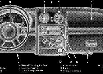
HAZARD WARNING FLASHERS Your vehicle’s hazard warning flasher is an emergency warning system. When you activate it, all front and rear directional signals will flash intermittently. Use it when your vehicle is disabled on or near the road. It warns other drivers to steer clear of you and your vehicle. This is an emergency warning system, not to be used when the vehicle is in motion. To activate the warning flashers, press the button on the instrument panel (between center air outlets). To turn the warning flashers off, press the button again.
NOTE: With extended use, the flashers may run down your battery.
IF YOUR ENGINE OVERHEATS In any of the following situations, you can reduce the potential for overheating by taking the appropriate ac- tion. † On the highways — Slow down. † In city traffic — While stopped, put transmission in N
(Neutral), but do not increase engine idle speed.
NOTE: There are steps that you can take to slow down an impending overheat condition. If your air conditioner is on, turn it off. The air conditioning system adds heat to the engine cooling system and turning off the A/C removes this heat. You can also turn the Temperature Control to maximum heat, the Mode Control to floor, and the Fan Control to High. This allows the heater core to act as a supplement to the radiator and aids in removing heat from the engine cooling system.
WHAT TO DO IN EMERGENCIES 273
CAUTION!
Driving with a hot cooling system could damage your vehicle. If the temperature gauge reads “H”, pull over and stop the vehicle. Idle the vehicle with the air conditioner turned off until the pointer drops back into the normal range. If the pointer remains on the “H”, and you hear continuous chimes, turn the engine off immediately, and call for service.
274 WHAT TO DO IN EMERGENCIES
CHANGING A FLAT TIRE
Jack And Lug Wrench Locations The jack, jack handle, and lug wrench are stored beneath the right rear seat. To remove the jack from its stowage position, turn the thumb screw counterclockwise to loosen jack assembly and then remove it.
WARNING!
† Always store the jack, lug wrench and spare, flat or damaged tire securely in the proper place. Never leave them loose in the vehicle where they could become dangerous projectiles during a quick stop or collision. † The jack is designed to use as a tool for changing tires only. The jack should not be used to lift the vehicle for service purposes, unless suitable sup- ports are placed under the vehicle as a safety measure. The vehicle should be jacked on a firm level surface only. Avoid ice or slippery areas.
Spare Tire Location To remove the spare tire from the carrier, remove the tire cover, if equipped, and remove the lug nuts with the lug wrench turning them counterclockwise.
WHAT TO DO IN EMERGENCIES 275
If you have added aftermarket accessories to the NOTE: spare tire mounted carrier, it cannot exceed a gross weight of 50 lbs (23 kg) including the weight of the spare tire. Tire Changing Procedures
WARNING!
You can be injured or killed if you try to change a wheel too close to moving traffic. Pull far enough off the road to avoid being hit when operating the jack or changing the wheel.
276 WHAT TO DO IN EMERGENCIES
Preparation † Park on a firm, level surface well off the road, to provide ample work space. Place automatic transmis- sion in P (Park), or manual transmission in R (Re- verse), and stop engine. Set parking brake firmly and activate hazard warning flasher. † Block tire diagonally oppo- site tire to be changed to pre- vent forward and backward vehicle movement.
Instructions 1. Remove spare tire, jack and tools from stored location. 2. Before raising vehicle, loosen lug nuts on wheel with flat tire.
3. Assemble the jack and jacking tools as shown. Connect jack handle driver to extensions, then to lug wrench. 4. Locate the jack as shown. For the front tires, place it in the notch on the body weld seam behind wheel to be changed. For the rear tires, place it under the axle as shown. Position the jack handle on the jack.
Front Scissor Jack Location
WHAT TO DO IN EMERGENCIES 277
WARNING!
Raising the vehicle higher than necessary can make the vehicle less stable and cause an accident. It could slip off the jack and hurt someone near it. Raise the vehicle only enough to remove the tire.
6. Remove the lug nuts and wheel. 7. Position the spare wheel/tire on the vehicle and install lug nuts with cone-shaped end toward wheel. Lightly tighten nuts clockwise. To avoid the risk of forcing the vehicle off the jack, do not tighten the nuts fully until the vehicle has been lowered. 8. Lower the vehicle by using a counterclockwise rota- tion to lower the jack.
Rear Scissor Jack Location
5. Raise the vehicle by turning the jack handle clockwise until the tire clears the ground.
278 WHAT TO DO IN EMERGENCIES
9. Finish tightening the lug nuts securely in crisscross pattern. Have an authorized service technician check that the torque is 85-110 ft. lbs. (115-149 N·m) as soon as possible.
10. Remove jack assembly and wheel blocks. 11. Secure jack, extension, and tire in proper locations.
lug wrench,
jack handle driver,
jack
WARNING!
Carefully follow these tire changing warnings to help prevent personal injury or damage to your vehicle: † Always park on a firm, level surface as far from the edge of the roadway as possible before raising the vehicle.
† Apply the parking brake firmly before jacking. † Always block the wheel diagonally opposite the wheel † Do not raise the vehicle higher than is necessary to † Never start the engine with the vehicle on a jack.
remove the tire.
being raised.
jack.
† Do not let passengers sit in the vehicle when it is on a † Do not get under the vehicle when it is on a jack. † Failure to follow the “Tire Changing Procedure” may result in personal injury or damage to your vehicle. † Only use the jack in the positions indicated. JUMP STARTING PROCEDURE
NOTE: Check the charge indicator on the battery. If the indicator is light or yellow, replace the battery. 1. Wear eye protection and remove any metal jewelry such as watch bands or bracelets that might make an unintended electrical contact. 2. When boost is provided by a battery in another vehicle, park that vehicle within booster cable reach but without letting the vehicles touch. Set the parking brake,
WHAT TO DO IN EMERGENCIES 279
place the automatic transmission in P (Park), or manual transmission in N (Neutral), and turn the ignition to OFF for both vehicles. 3. Turn off the heater, radio and all unnecessary electrical loads. 4. Connect one end of a jumper cable to the positive terminal of the discharged battery. Connect the other end of the same cable to the positive terminal of the booster battery. 5. Connect the other cable, first to the negative terminal of the booster battery and then connect the other end to a non-paint metal surface on the engine of the vehicle with the discharged battery. Make sure you have a good contact on the engine. 6. Start the engine in the vehicle which has the booster battery, let the engine idle a few minutes, then start the engine in the vehicle with the discharged battery.
280 WHAT TO DO IN EMERGENCIES
7. When removing the jumper cables, reverse the above sequence exactly. Be careful of the moving belts and fan. NOTE: To start the vehicle following connection of a booster battery, the Security Alarm System must first be disabled by cycling a front door key cylinder or by using the keyless entry transmitter.
WARNING!
Jump starting can be dangerous. To avoid personal injury or damage to electrical components in vehicle, observe the following warnings: † Battery fluid is a corrosive acid solution and can burn or even blind you. Don’t allow battery fluid to contact your eyes, skin, or clothing. Don’t lean over a battery
when attaching clamps. If acid splashes in eyes or on skin, flush the area immediately with large amounts of water. † Do not use a booster battery or any other booster source that has a greater than 12–volt system, i.e., do not use a 24–volt power source. † Never attempt to jump start a discharged battery that is frozen, because it could rupture or explode during jump starting. † Be sure your vehicle is not touching the jump start † Observe all Battery Warnings in Section 7 of this
vehicle.
manual, while jump starting your vehicle.
WARNING!
WARNING!
WHAT TO DO IN EMERGENCIES 281
Stand clear of vehicles when pulling with tow hooks. Tow straps and chains may break, causing serious injury.
TOWING A DISABLED VEHICLE The manufacturer recommends towing with all four wheels off the ground. Acceptable methods are to tow the vehicle on a flatbed or with one end of the vehicle raised and the other end on a towing dolly.
Do not attempt to push or tow your vehicle to get it started. Unburned fuel could enter the catalytic converter and, once the engine has started, ignite and damage the converter and vehicle.
EMERGENCY TOW HOOKS — IF EQUIPPED If your vehicle is equipped with tow hooks, they are mounted in the front and the rear.
CAUTION!
Tow hooks are for emergency use only, to rescue a vehicle stranded off road. Do not use tow hooks for tow truck hookup or highway towing. You could damage your vehicle. Tow straps are recommended when towing the vehicle, chains may cause vehicle damage.
MAINTAINING YOUR VEHICLE
CONTENTS
m 2.4L Engine . . . . . . . . . . . . . . . . . . . . . . . . . . . 285
m 3.7L Engine . . . . . . . . . . . . . . . . . . . . . . . . . . . 286
m Onboard Diagnostic System — OBD II . . . . . . . . 287
m Emissions Inspection And MaintenancePrograms
. . . . . . . . . . . . . . . . . . . . . . . . . . . . 288
m Replacement Parts . . . . . . . . . . . . . . . . . . . . . . 289
m Dealer Service . . . . . . . . . . . . . . . . . . . . . . . . . 289
m Maintenance Procedures . . . . . . . . . . . . . . . . . . 290
. . . . . . . . . . . . . . . . . . . . . . . . . . 290N Engine Oil
N Drive Belts — Check Condition And Tension . . 294
N Spark Plugs . . . . . . . . . . . . . . . . . . . . . . . . . 295
N Catalytic Converter . . . . . . . . . . . . . . . . . . . . 295
N Engine Timing Belt — 2.4L Engine . . . . . . . . . 297
N Ignition Wiring System — 2.4L Engine . . . . . . 297
N Crankcase Emission Control System . . . . . . . . 297
N Air Cleaner Filter . . . . . . . . . . . . . . . . . . . . . 297
N Maintenance-Free Battery . . . . . . . . . . . . . . . . 298
N Air Conditioner Maintenance . . . . . . . . . . . . . 299284 MAINTAINING YOUR VEHICLE
N Power Steering Fluid Check . . . . . . . . . . . . . . 300
N Driveline And Steering ComponentLubrication . . . . . . . . . . . . . . . . . . . . . . . . . . 301
N Body Lubrication . . . . . . . . . . . . . . . . . . . . . 301
N Windshield Wiper Blades . . . . . . . . . . . . . . . . 301
N Windshield Washers . . . . . . . . . . . . . . . . . . . 302
N Exhaust System . . . . . . . . . . . . . . . . . . . . . . 302
N Cooling System . . . . . . . . . . . . . . . . . . . . . . . 303
N Hoses And Vacuum/Vapor Harnesses . . . . . . . 307
N Brake System . . . . . . . . . . . . . . . . . . . . . . . . 308
N Automatic Transmission . . . . . . . . . . . . . . . . 311
N Hydraulic Clutch Fluid— Manual Transmission . . . . . . . . . . . . . . . . 313
N Manual Transmission . . . . . . . . . . . . . . . . . . 313N Transfer Case . . . . . . . . . . . . . . . . . . . . . . . . 313
N Front/Rear Axle Fluid . . . . . . . . . . . . . . . . . . 315
N Appearance Care And Protection Fromm Fuse Panel
Corrosion . . . . . . . . . . . . . . . . . . . . . . . . . . . 315
. . . . . . . . . . . . . . . . . . . . . . . . . . . 320
N Interior Fuses . . . . . . . . . . . . . . . . . . . . . . . . 320
N Underhood Fuses (Power Distribution Center) . 323
m Vehicle Storage . . . . . . . . . . . . . . . . . . . . . . . . 324
m Replacement Bulbs . . . . . . . . . . . . . . . . . . . . . . 324
m Fluid Capacities . . . . . . . . . . . . . . . . . . . . . . . . 326
m Recommended Fluids, Lubricants And GenuineParts . . . . . . . . . . . . . . . . . . . . . . . . . . . . . . . . 327
N Engine . . . . . . . . . . . . . . . . . . . . . . . . . . . . . 327
N Chassis . . . . . . . . . . . . . . . . . . . . . . . . . . . . 3282.4L ENGINE
MAINTAINING YOUR VEHICLE 285
286 MAINTAINING YOUR VEHICLE
3.7L ENGINE
ONBOARD DIAGNOSTIC SYSTEM — OBD II Your vehicle is equipped with a sophisticated onboard diagnostic system called OBD II. This system monitors the performance of the emissions, engine, and automatic transmission control systems. When these systems are operating properly, your vehicle will provide excellent performance and fuel economy, as well as engine emis- sions well within current government regulations. If any of these systems require service, the OBD II system will turn on the “Malfunction Indicator Light.” It will also store diagnostic codes and other information to assist your service technician in making repairs. Al- though your vehicle will usually be drivable and not need towing, see your dealer for service as soon as possible.
MAINTAINING YOUR VEHICLE 287
CAUTION!
† Prolonged driving with the “Malfunction Indica- tor Light” on could cause further damage to the emission control system. It could also affect fuel economy and driveability. The vehicle must be serviced before any emissions tests can be per- formed. † If the “Malfunction Indicator Light” is flashing while the engine is running, severe catalytic con- verter damage and power loss will soon occur. Immediate service is required.
288 MAINTAINING YOUR VEHICLE
EMISSIONS INSPECTION AND MAINTENANCE PROGRAMS In some localities, it may be a legal requirement to pass an inspection of your vehicle’s emissions control system. Failure to pass could prevent vehicle registration.
For states which have an I/M (Inspection and Maintenance) requirement, this check verifies the following: the MIL (Malfunction Indicator Lamp) is functioning and is not on when the engine is running, and that the OBD (On Board Diagnostic) system is ready for testing. Normally, the OBD system will be ready. The OBD system may not be ready if your vehicle was recently serviced, if you recently had a dead battery, or a battery replacement. If the OBD system should be determined not ready for the I/M test, your vehicle may fail the test.
Your vehicle has a simple ignition key actuated test which you can use prior to going to the test station. To check if your vehicle’s OBD system is ready, you must do the following: 1. Insert your ignition key into the ignition switch. 2. Turn the ignition to the ON position, but do not crank or start the engine. 3. If you crank or start the engine, you will have to start this test over. 4. As soon as you turn your key to the ON position, you will see your MIL symbol come on as part of a normal bulb check. 5. Approximately 15 seconds later, one of two things will happen:
a. The MIL will flash for about 10 seconds and then return to being fully illuminated until you turn off the
ignition key or start the engine. This means that your vehicle’s OBD system is not ready and you should not proceed to the I/M station. b. The MIL will not flash at all and will remain fully illuminated until you turn off the ignition key or start the engine. This means that your vehicle’s OBD system is ready and you can proceed to the I/M station.
If your OBD system is not ready, you should see your authorized dealer or repair facility. If your vehicle was recently serviced or had a battery failure or replacement, you may need to do nothing more than drive your vehicle as you normally would in order for your OBD system to update. A recheck with the above test routine may then indicate that the system is now ready. Regardless of whether your vehicle’s OBD system is ready or not ready, if the MIL symbol is illuminated during normal vehicle operation, you should have your
MAINTAINING YOUR VEHICLE 289
vehicle serviced before going to the I/M station. The I/M station can fail your vehicle because the MIL symbol is on with the engine running.
REPLACEMENT PARTS Use of genuine Mopart parts for normal/scheduled maintenance and repairs is highly recommended to in- sure the designed performance. Damage or failures caused by the use of non-Mopart parts for maintenance and repairs will not be covered by the manufacturer’s warranty.
DEALER SERVICE Your dealer has the qualified service personnel, special tools and equipment to perform all service operations in an expert manner. Service Manuals are available which include detailed service information for your vehicle. Refer to these manuals before attempting any procedure yourself.
290 MAINTAINING YOUR VEHICLE
NOTE: systems can result against you.
Intentional tampering with emissions control in civil penalties being assessed
WARNING!
You can be badly injured working on or around a motor vehicle. Do only that service work for which you have the knowledge and the proper equipment. If you have any doubt about your ability to perform a service job, take your vehicle to a competent mechanic.
MAINTENANCE PROCEDURES The pages that follow contain the required maintenance services determined by the engineers who designed your vehicle. Besides the maintenance items for which there are fixed maintenance intervals, there are other items that should operate satisfactorily without periodic maintenance. However, if a malfunction of these items does occur, it could adversely affect the engine or vehicle performance. These items should be inspected if a malfunction is observed or suspected. Engine Oil
Checking Oil Level To assure proper lubrication of your vehicle’s engine, the engine oil must be maintained at the correct level. Check the oil level at regular intervals, such as every fuel stop.
The best time to check the engine oil level is about 5
minutes after a fully warmed engine has been shut off, or before starting the engine after it has sat overnight.MAINTAINING YOUR VEHICLE 291
2.4L Engines
3.7L Engines
Checking the oil while the vehicle is on level ground will improve the accuracy of the oil level readings. Maintain the oil level between the ADD and SAFE markings on the dipstick. Adding 1 U.S. Quart (0.95L) of oil when the reading is at the ADD mark will result in a SAFE reading on these engines.
292 MAINTAINING YOUR VEHICLE
CAUTION!
Overfilling or underfilling the crankcase will cause aeration or loss of oil pressure. This could damage your engine.
Change Engine Oil Road conditions as well as your kind of driving affect the interval at which your oil should be changed. Check the following to determine if any apply to you: † Day or night temperatures are below 32°F (0°C) † Stop and go driving † Extensive engine idling † Driving in dusty conditions † Short trip driving of less than 10 miles (16.2 km)
speeds during hot weather, above 90°F (32°C)
† More than 50% of your driving is at sustained high † Taxi, Police, or delivery service (commercial service) † Trailer towing † Off-road or desert driving If ANY of these apply to you, then change your engine oil at every interval shown in schedule “B” of the “Mainte- nance Schedules” section of this manual. If none of these apply to you, then change your engine oil at every interval shown on schedule “A” of the “Main- tenance Schedules” section of this manual NOTE: Under no circumstances should oil change in- tervals exceed 6,000 miles (10 000 km) or 6 months whichever comes first.
Engine Oil Selection For best performance and maximum protection for all engines under all types of operating conditions, the manufacturer recommends engine oils that are API Cer- tified and meet the requirements of DaimlerChrysler Material Standard MS-6395. American Petroleum Institute (API) Engine Oil Identification Symbol
This symbol means that the oil has been certified by the American Petroleum Institute (API). The manufacturer only recommends API Certified engine oils.
MAINTAINING YOUR VEHICLE 293
Engine Oil Viscosity Chart The proper SAE viscosity grade of engine oil should be selected based on the following recommendation and be within the operating temperature shown in the engine oil viscosity chart.
294 MAINTAINING YOUR VEHICLE
Materials Added To Engine Oils The manufacturer strongly recommends against the ad- dition of any additives (other than leak detection dyes) to engine oil. Engine oil is an engineered product and it’s performance may be impaired by supplemental addi- tives. Disposing of Used Engine Oil Care should be taken in disposing of used engine oil from your vehicle. Used oil and oil filters, indiscriminately discarded, can present a problem to the environment. Contact your authorized dealer, service station, or gov- ernmental agency for advice on how and where used oil can be safely discarded in your area. Engine Oil Filter The engine oil filter should be replaced at every engine oil change.
Engine Oil Filter Selection All of the manufacturer’s engines have a full-flow type disposable oil filter. Use a filter of this type for replace- ment. The quality of replacement filters varies consider- ably. Only high quality filters should be used to assure most efficient service. Mopart engine oil filters are high quality oil filters and are recommended. Drive Belts — Check Condition and Tension At the mileage shown in the appropriate “Maintenance Schedule,” check all drive belts for condition and proper tension. Improper belt tension can cause belt slippage and failure. Inspect the drive belt for evidence of cuts, cracks, or glazing and replace them if there is any sign of damage which could result in belt failure. If adjustment is re- quired, adjust the belts according to the specifications and procedures shown in the Service Manual.
Special tools are required to properly measure tension and to restore belt tension to factory specifications. Also, check belt routing to make sure there is no interference between the belts and other engine components. Spark Plugs Spark plugs must fire properly to assure engine perfor- mance and emission control. New plugs should be in- stalled at the mileage specified in the appropriate main- tenance chart. The entire set should be replaced if there is any malfunction due to a faulty spark plug. Refer to the “Vehicle Emission Control Information” label in the engine compartment for spark plug information. Catalytic Converter The catalytic converter requires the use of unleaded fuel only. Leaded gasoline will destroy the effectiveness of the converter as an emission control device.
MAINTAINING YOUR VEHICLE 295
Under normal operating conditions, the catalytic con- verter will not require maintenance. However, it is im- portant to keep the engine properly tuned to assure proper catalyst operation and prevent possible catalyst damage.
CAUTION!
Damage to the catalytic converter can result if your vehicle is not kept in proper operating condition. In the event of engine malfunction, particularly involv- ing engine misfire or other apparent loss of perfor- mance, have your vehicle serviced promptly. Contin- ued operation of your vehicle with a severe malfunction could cause the converter to overheat, resulting in possible damage to the converter and vehicle.
296 MAINTAINING YOUR VEHICLE
WARNING!
A hot exhaust system can start a fire if you park over materials that can burn. Such materials might be grass or leaves coming into contact with your ex- haust system. Do not park or operate your vehicle in areas where your exhaust system can contact any- thing that can burn.
In unusual situations involving grossly malfunctioning engine operation, a scorching odor may suggest severe and abnormal catalyst overheating. If this occurs, stop the vehicle, turn off the engine and allow it to cool. Service, including a tune up to manufacturer’s specifica- tions, should be obtained immediately. To minimize the possibility of catalytic converter dam- age:
vehicle.
† Do not shut off the engine or interrupt the ignition when the transmission is in gear and the vehicle is in motion. † Do not try to start the engine by pushing or towing the † Do not idle the engine with any spark plug wires disconnected or removed, such as when diagnostic testing. † Do not idle the engine for prolonged periods during very rough idle or malfunctioning operating condi- tions.
† Do not allow vehicle to run out of fuel. NOTE: systems can result against you.
Intentional tampering with emissions control in civil penalties being assessed
Engine Timing Belt — 2.4L Engine
Replace the engine timing belt at the intervals described in the appropriate maintenance schedule. Ignition Wiring System — 2.4L Engine
Replace the ignition cables at the intervals described in the appropriate maintenance schedule. Crankcase Emission Control System Proper operation of this system depends on freedom from sticking or plugging due to deposits. As vehicle mileage builds up, the PCV valve and passages may accumulate deposits. If a valve is not working properly, replace it with a new valve. DO NOT ATTEMPT TO CLEAN THE OLD PCV VALVE! Check ventilation hose for indication of damage or plugging deposits. Replace if necessary.
MAINTAINING YOUR VEHICLE 297
Air Cleaner Filter Under normal driving conditions, replace the air filter at the intervals shown on “Maintenance Schedule A.” If, however, you drive the vehicle frequently under dusty or severe conditions, the filter element should be inspected periodically and replaced if necessary at the intervals shown on “Maintenance Schedule B.”
WARNING!
The air cleaner can provide protection in the case of engine backfire. Do not remove the air cleaner unless it is necessary for repair or maintenance. Make sure that no one is near the engine compart- ment before starting the vehicle with the air cleaner removed. Failure to do so can result in serious personal injury.
298 MAINTAINING YOUR VEHICLE
Maintenance-Free Battery Your vehicle is equipped with a maintenance-free battery. You will never have to add water, nor is periodic main- tenance required.
WARNING!
Battery posts, terminals, and related accessories con- tain lead and lead compounds. Always wash hands after handling the battery.
To determine the battery charge, check the battery test indicator (if equipped) on top of the battery. Refer to the illustration.
MAINTAINING YOUR VEHICLE 299
WARNING!
† Use only refrigerants and compressor lubricants approved by the manufacturer for your air condi- tioning system. Some unapproved refrigerants are flammable and can explode, injuring you. Other unapproved refrigerants or lubricants can cause the system to fail, requiring costly repairs. † The air conditioning system contains refrigerant under high pressure. To avoid risk of personal injury or damage to the system, adding refrigerant or any repair requiring lines to be disconnected should be done by an experienced repairman.
CAUTION!
It is essential when replacing the cables on the battery that the positive cable is attached to the positive post and the negative cable is attached to the negative post. Battery posts are marked (+) positive and negative (-) and identified on the battery case. Also, if a “fast charger” is used while battery is in the vehicle, disconnect both vehicle battery cables be- fore connecting the charger to battery. Do not use a “fast charger” to provide starting voltage.
Air Conditioner Maintenance For best possible performance, your air conditioner should be checked and serviced by an Authorized Dealer at the start of each warm season. This service should include cleaning of the condenser fins and a performance test. Drive belt tension should also be checked at this time.
300 MAINTAINING YOUR VEHICLE
Refrigerant Recovery and Recycling R-134a Air Conditioning Refrigerant is a hydrofluorocar- bon (HFC) that is endorsed by the Environmental Pro- tection Agency and is an ozone-saving product. How- ever, the manufacturer recommends that air conditioning service be performed by dealers or other service facilities using recovery and recycling equipment. NOTE: Air Conditioning systems found to be contami- nated with A/C System Sealers, Stop Leak Products, Seal Conditioners, Compressor Oil, or Refrigerants not ap- proved by the manufacturer, voids the warranty for the Air Conditioning system. Power Steering Fluid Check Checking the power steering fluid level at a defined service interval is not required. The fluid should only be checked if a leak is suspected, abnormal noises are
apparent, and/or the system is not functioning as antici- pated. Coordinate inspection efforts through a certified “DaimlerChrysler Dealership.”
WARNING!
Fluid level should be checked on a level surface with the engine off to prevent injury from moving parts, and to insure accurate fluid level reading. Do not overfill. Use only the manufacturer’s recommended fluid.
If necessary, add fluid to restore to the proper indicated level. With a clean cloth, wipe any spilled fluid from all surfaces. Refer to Recommended Fluids, Lubricants, and Genuine Parts for correct fluid type.
Driveline And Steering Component Lubrication U-joints (cardan joints) are sealed and do not require lubrication. Prop shafts, yokes, ball joints and other driveline and steering components may be provided with grease fittings for lubrication. Lubrication of these com- ponents at the intervals specified in the appropriate “Maintenance Schedule” in Section 8 is very important, particularly if your vehicle is subjected to off-road or other heavy-duty use. See your authorized dealer for complete service information. Body Lubrication Locks and all body pivot points, including such items as seat tracks, doors, swing gate and hood hinges, should be lubricated periodically to assure quiet, easy operation and to protect against rust and wear. Prior to the appli- cation of any lubricant, the parts concerned should be wiped clean to remove dust and grit; after lubricating excess oil and grease should be removed. Particular
MAINTAINING YOUR VEHICLE 301
attention should also be given to hood latching compo- nents to insure proper function. When performing other underhood services, the hood latch, release mechanism and safety catch should be cleaned and lubricated. The external lock cylinders should be lubricated twice a year, preferably in the fall and spring. Apply a small amount of a high quality lubricant such as Mopart Lock Cylinder Lubricant directly into the lock cylinder. Windshield Wiper Blades Clean the rubber edges of the wiper blades and the windshield periodically with a sponge or soft cloth and a mild non-abrasive cleaner. This will remove accumula- tions of salt or road film. Operation of the wipers on dry glass for long periods may cause deterioration of the wiper blades. Always use washer fluid when using the wipers to remove salt or dirt from a dry windshield. Avoid using the wiper blades to
302 MAINTAINING YOUR VEHICLE
remove frost or ice from the windshield. Keep the blade rubber out of contact with petroleum products such as engine oil, gasoline, etc. Windshield Washers
should be checked for fluid level at regular intervals. Fill the reservoir with windshield washer solvent (not radia- tor antifreeze) and operate the system for a few seconds to flush out the residual water.
WARNING!
Commercial windshield washer solvents are flam- mable. They could ignite and burn you. Care must be exercised when filling or working around the washer solution.
Exhaust System The best protection against carbon monoxide entry into the vehicle body is a properly maintained engine exhaust system. If you notice a change in the sound of the exhaust system; or if the exhaust fumes can be detected inside the vehicle;
The fluid reservoir for the windshield washers and the rear window washer is shared. It is located in the front of the engine compartment on the passenger side and
or when the underside or rear of the vehicle is damaged; have an authorized technician inspect the complete ex- haust system and adjacent body areas for broken, dam- aged, deteriorated, or mispositioned parts. Open seams or loose connections could permit exhaust fumes to seep into the passenger compartment. In addition, inspect the exhaust system each time the vehicle is raised for lubri- cation or oil change. Replace as required. Cooling System
WARNING!
You or others can be badly burned by hot coolant or steam from your radiator. If you see or hear steam coming from under the hood, don’t open the hood until the radiator has had time to cool. Never try to open a cooling system pressure cap when the radia- tor or coolant bottle is hot.
MAINTAINING YOUR VEHICLE 303
Coolant Checks Check coolant protection every 12 months (before the onset of freezing weather, where applicable). If coolant is dirty or rusty in appearance, the system should be drained, flushed and refilled with fresh coolant. Check the front of the radiator for any accumulation of bugs, leaves, etc. Clean the radiator by gently spraying water from a garden hose at the back of the core. Check the engine cooling system hoses for condition and tightness of connection. Inspect the entire system for leaks. Any hoses that show cuts or severe abrasion must be replaced. Cooling System — Drain, Flush, And Refill At the intervals shown in the appropriate “Maintenance Schedule,” the system should be drained, flushed, and refilled.
304 MAINTAINING YOUR VEHICLE
If the solution is dirty and contains a considerable amount of sediment, clean and flush with reliable cooling system cleaner. Follow with a thorough rinsing to remove all deposits and chemicals. Engine Coolant Disposal Used ethylene glycol based engine coolant is a regulated substance requiring proper disposal. Check with your local authorities to determine the disposal rules for your community. Do not store ethylene glycol based engine coolant in open containers or allow it to remain in puddles on the ground. Prevent ingestion by animals or children. If ingested by a child, contact a physician immediately. Selection Of Coolant Use only the manufacturer’s recommended coolant, refer to Recommended Fluids, Lubricants, and Genuine Parts for correct coolant type.
CAUTION!
† Mixing of coolants other than the specified HOAT coolant may result in decreased corrosion protec- tion and engine damage that may not be covered under the new vehicle warranty. If a non-HOAT coolant is introduced into the cooling system in an emergency, it should be replaced with the speci- fied coolant as soon as possible. † Do not use plain water alone or alcohol base antifreeze products. Do not use additional rust inhibitors or antirust products, as they may not be compatible with the radiator coolant and may plug the radiator. † This vehicle has not been designed for use with Propylene Glycol based coolants. Use of Propy- lene Glycol base coolants is not recommended.
Adding Coolant When adding coolant, a minimum solution of 50% rec- ommended ethylene glycol antifreeze coolant in water