- 2007 Hyundai Sonata Owners Manuals
- Hyundai Sonata Owners Manuals
- 2006 Hyundai Sonata Owners Manuals
- Hyundai Sonata Owners Manuals
- 2003 Hyundai Sonata Owners Manuals
- Hyundai Sonata Owners Manuals
- 2004 Hyundai Sonata Owners Manuals
- Hyundai Sonata Owners Manuals
- 2011 Hyundai Sonata Owners Manuals
- Hyundai Sonata Owners Manuals
- 2013 Hyundai Sonata Owners Manuals
- Hyundai Sonata Owners Manuals
- 2005 Hyundai Sonata Owners Manuals
- Hyundai Sonata Owners Manuals
- 2009 Hyundai Sonata Owners Manuals
- Hyundai Sonata Owners Manuals
- 2008 Hyundai Sonata Owners Manuals
- Hyundai Sonata Owners Manuals
- 2010 Hyundai Sonata Owners Manuals
- Hyundai Sonata Owners Manuals
- Download PDF Manual
-
The vapor hose and fuel filler cap should be inspected at those intervals specified in the maintenance schedule. Make sure that a new vapor hose or fuel filler cap is correctly re- placed.
F060H01A-AAT o Air cleaner filter
A Genuine Hyundai air cleaner filter is recom- mended when filter is replaced.
F060J01A-AAT o Spark plugs
Make sure to install new spark plugs of the correct heat range.
F060E01A-AAT o Timing belt
Inspect all parts related to the timing belt for damage and deformation. Replace any dam- aged parts immediately.
F070C01A-AAT o Coolant
The coolant should be changed at the intervals specified in the maintenance schedule.
5- 8 VEHICLE MAINTENANCE REQUIREMENTS
F070D01A-AAT o Manual transaxle oil
F070G02A-AAT o Brake Fluid
F070K01A-AAT o Exhaust Pipe and Muffler
Inspect the manual transaxle oil according to the maintenance schedule.
NOTE: If the oil level is low, check for possible leaks before adding oil. Do not overfill.
F070E04A-AAT o Automatic Transaxle Fluid and Filter
The fluid level should be in the "HOT" range of the dipstick, after the engine and transaxle are at normal operating temperature. Check the automatic transaxle fluid level with the engine running and the transaxle in neutral, with the parking brake properly applied. Use Genuine Hyundai ATF or DIAMOND ATF SP-III or SK ATF SP-III when adding or changing fluid.
F070F01A-AAT o Brake Hoses and Lines
Visually check for proper installation, chafing, cracks, deterioration and any leakage. Replace any deteriorated or damaged parts immedi- ately.
Check brake fluid level in the brake fluid reser- voir. The level should be between "MIN" and "MAX" marks on the side of the reservoir. Use only hydraulic brake fluid conforming to DOT 3
or DOT 4.Visually inspect the exhaust pipes, muffler and hangers for cracks, deterioration, or damage. Start the engine and listen carefully for any exhaust gas leakage. Tighten connections or replace parts as necessary.
F070H01A-AAT o Rear Brake Drums and Linings/
Parking Brake
Check the rear brake drums and linings for scoring, burning, leaking fluid, broken parts, and excessive wear. Inspect the parking brake system including the parking brake lever and cables. For detailed service procedures, refer to the Shop Manual.
F070J01A-AAT o Brake Pads, Calipers and Rotors
Check the pads for excessive wear, discs for run out and wear, and calipers for fluid leakage.
F070L01A-AAT o Suspension Mounting Bolts
Check the suspension connections for loose- ness or damage. Retighten to the specified torque.
F070M01Y-AAT o Steering Gear Box, Linkage & Boots/ Lower Arm Ball Joint, Upper Arm Ball Joint
With the vehicle stopped and engine off, check for excessive free-play in the steering wheel. Check the linkage for bends or damage. Check the dust boots and ball joints for deterioration, cracks, or damage. Replace any damaged parts.
VEHICLE MAINTENANCE REQUIREMENTS 5- 9
F070N01A-AAT o Power Steering Pump, Belt and Hoses
Check the power steering pump and hoses for leakage and damage. Replace any damaged or leaking parts immediately. Inspect the power steering belt for evidence of cuts, cracks, ex- cessive wear, oiliness and proper tension. Replace or adjust it if necessary.
F070P01A-AAT o Driveshafts and Boots
Check the drive shafts, boots and clamps for cracks, deterioration, or damage. Replace any damaged parts and, if necessary, repack the grease.
F070Q01A-AAT o Air Conditioning Refrigerant
Check the air conditioning lines and connec- tions for leakage and damage. Check air con- ditioning performance according to the relevant shop manual if necessary.
6. Do-It-Yourself Maintenance
Engine compartment ........................................................................6-2
General checks ................................................................................6-4
Checking the engine oil ....................................................................6-5
Changing the oil and filter .................................................................6-6
Checking and changing the engine coolant......................................6-7
Spark plugs ......................................................................................6-9
Changing the air cleaner filter .........................................................6-11
Checking the transaxle oil (Manual) ...............................................6-12
Checking the transaxle fluid (Automatic) .......................................6-13
Checking the brakes ......................................................................6-14
Air conditioning care .......................................................................6-15
Checking drive belts ......................................................................6-18
Checking and replacing fuses ........................................................6-18
Replacement of bulbs ....................................................................6-21
Junction Box description ................................................................6-296- 2 DO-IT-YOURSELF MAINTENANCE
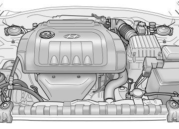
G010A02Y-GAT ENGINE COMPARTMENT (2.4 DOHC)
2 3
9 10 11 12
13
14
HEF-064
1. Engine oil filler cap 2. Brake Booster 3. Brake fluid reservoir 4. Clutch fluid reservoir (If installed) 5. Under hood junction box
6. Windshield washer fluid reservoir 7. Power steering fluid reservoir 8. Engine oil level dipstick 9. Engine cover
10.Automatic transaxle fluid level dipstick
(If installed) 11.Radiator cap 12.Air cleaner 13.Coolant reservoir cap 14.Battery
G010B03Y-AAT ENGINE COMPARTMENT (2.7 V6 Delta)
DO-IT-YOURSELF MAINTENANCE 6- 3
1 2 3
9 10
1112 13
G010B04Y
1. Air cleaner 2. Brake fluid reservoir 3. Brake booster 4. Windshield washer fluid reservoir 5. Power steering fluid reservoir
6. Engine oil level dipstick 7. Engine cover 8. Engine oil filler cap 9. Automatic transaxle fluid level dipstick
(If installed)
10.Radiator cap 11.Battery 12.Coolant reservoir cap 13.Under hood junction box
6- 4 DO-IT-YOURSELF MAINTENANCE
G020A01A-AAT GENERAL CHECKS
G020B01A-AAT Vehicle Exterior
G020C01A-AAT Vehicle Interior
Engine Compartment The following should be checked regularly:
o Engine oil level and condition o Transaxle fluid level and condition o Brake fluid level o Clutch fluid level o Engine coolant level o Windshield washer fluid level o Accessory drive belt condition o Engine Coolant hose condition o Fluid leaks (on or below components) o Power steering fluid level o Battery condition
The following should be checked monthly:
o Overall appearance and condition o Air filter condition o Wheel condition and wheel nut torque o Exhaust system condition o Light condition and operation o Windshield glass condition o Wiper blade condition o Paint condition and body corrosion o Fluid leaks o Door and hood lock condition o Tire pressure and condition (including spare
tire)
The following should be checked each time when the vehicle is driven:
o Lights operation o Windshield wiper operation o Horn operation o Defroster, heating system operation (and air
conditioning, if installed)
o Steering operation and condition o Mirror condition and operation o Turn signal operation o Accelerator pedal operation o Brake operation, including parking brake o Manual transaxle operation, including clutch
operation
o Automatic transaxle operation, including
"Park" mechanism operation
o Seat control condition and operation o Seat belt condition and operation o Sunvisor operation
If you notice anything that does not operate correctly or appears to be functioning incor- rectly, inspect it carefully and seek assistance from your Hyundai dealer if service is needed.
G030A01A-AAT CHECKING THE ENGINE OIL
G030B01A-AAT Recommended Oil
G030C02A-AAT To Check the Oil Level
DO-IT-YOURSELF MAINTENANCE 6- 5
Engine oil is essential to the performance and service of the engine. It is suggested that you check the oil level at least once a week in normal use and more often if you are on a trip or driving in severe conditions.
SH, SG or SG/CD (API) multi-grade and fuel efficient oil is recommended.
G030A02A
G030C01Y Before checking the oil, warm up the engine to the normal operating temperature and be sure your car is parked on level ground. Turn the engine off.
Wait five minutes, then remove the dipstick, wipe it off, fully reinsert the dipstick and withdraw it again. Then note the highest level the oil has reached on the dipstick. It should be between the upper ("F") and lower ("L") range.
6- 6 DO-IT-YOURSELF MAINTENANCE
G030D01A-AAT Adding Oil
G040A02A-AAT CHANGING THE OIL AND FILTER
DOHC
V6
DOHC
V6
The engine oil and filter should be changed at those intervals specified in the maintenance schedule in Section 5. If the car is being driven in severe conditions, more frequent oil and filter changes are required.
The procedure for changing the oil and filter is as follows:
G030D01Y If the oil level is close to or below the "L" mark, add oil until it reaches the "F" mark. To add oil:
HSM394
1. Remove the oil filler cap by turning it counter-
2. Add oil, then check the level again. Do not
clockwise.
overfill.
3. Replace the cap by turning it clockwise.
1. Park the car on level ground and set the parking brake. Start the engine and let it warm up until the needle on the coolant temperature gauge moves above the lowest mark. Turn the engine off and place the gear selector lever in "P" (automatic) or reverse gear (manual transaxle). Set the parking brake.
2. Open the hood and remove the engine oil
filler cap.
3. Slide underneath the car and loosen the drain plug by turning it counterclockwise with a wrench of the proper size. Be sure that a drain pan is in position to catch the oil as it drains out, then remove the drain plug.
The distance between the "F" and "L" marks is equal to about 1 quart of oil.
WARNING:
Be very careful when draining the engine oil as it may be hot enough to burn you!
DO-IT-YOURSELF MAINTENANCE 6- 7
G050A01A-AAT CHECKING AND CHANGING THE EN- GINE COOLANT
WARNING:
Do not remove the radiator cap when the engine is hot. When the engine is hot, the engine coolant is under pressure and may erupt through the opening if the cap is removed. You could be seriously burned if you do not observe this precaution. Do not remove the radiator cap until the radiator is cool to the touch.
NOTE: Always dispose of used engine oil in an environmentally acceptable manner. It is suggested that it be placed in a sealed container and taken to a service station for reclamation. Do not pour the oil on the ground or put it into the household trash.
WARNING:
Used motor oil may cause irritation or can- cer of the skin if left in contact with the skin for prolonged periods of time. Wash your hands thoroughly with soap and warm water as soon as possible after handling used oil.
4. When the oil has stopped draining, replace the drain plug using a new washer and retighten by turning it clockwise.
Tightening torque is: 3.5 ~ 4.5 kgf.m
5. Remove the oil filter by turning it counter- clockwise with a oil filter wrench of the proper size. A certain amount of oil will come out when you remove the filter. So be sure to have your drain pan in place underneath it. Install a new oil filter in accordance with the instructions on the carton or on the filter itself. Do not over-tighten.
6.
Tightening torque is: 1.2 ~ 1.6 kgf.m
Be sure that the mounting surface on the engine is clean and that the old gasket is removed completely. Lubricate the new gasket on the filter with clean engine oil before installation.
7. Refill the crankcase with the recommended engine oil. Refer to the specification in chap- ter 9 for engine oil capacity.
8. Start the engine and check to be sure no oil
is leaking from the drain plug or oil filter.
9. Shut off the engine and recheck the oil level.
6- 8 DO-IT-YOURSELF MAINTENANCE
G050B01A-AAT Recommended Engine Coolant
G050B01Y Use a high quality ethylene-glycol coolant in a 50/50 mix with water. The engine coolant should be compatible with aluminum engine parts. Additional corrosion inhibitors or additives should not be used. The cooling system must be maintained with the correct concentration and type of engine coolant to prevent freezing and corrosion. Never allow the concentration of antifreeze to exceed the 60% level or go below the 35% level, or damage to the cooling system may result. For proper concentration when adding or replacing the engine coolant, refer to the following table.
Ambient
Engine Coolant concentration
temperature
°C ( °F) -15 (5) -25 (-13) -35 (-31) -45 (-49)
Antifreeze solution
35% 40% 50% 60%
Water
65% 60% 50% 40%
G050C01A-AAT To Check the Coolant Level The coolant level can be seen on the side of the plastic coolant reservoir. The level of the cool- ant should be between the "L" and "F" lines on the reservoir when the engine is cool. If the level is below the "L" mark, add engine coolant to bring it up between "L" and "F". If the level is low, inspect for coolant leaks and recheck the fluid level frequently. If the level drops again, visit your Hyundai dealer for an inspection and diagnosis of the reason.
G050D02A-AAT To Change the Engine Coolant The engine coolant should be changed at those intervals specified in the vehicle maintenance schedule in Section 5.
CAUTION: Engine coolant can damage the finish of your car. If you spill engine coolant on the car, wash it off thoroughly with clean water.
1. Park the car on level ground, set the park- ing brake and remove the radiator cap when cool.
2. Be sure your drain receptacle is in place. Open the drain cock on the radiator. Allow all the engine coolant to drain from the cooling system, then securely close the drain cock. 3. Check Section 9 for the capacity of the cooling system in your car. Then, following the manufacturer's directions on the engine coolant container, add the appropriate quan- tity of coolant to the radiator.
4. Turn the radiator cap counterclockwise with- out pressing down on it, until it stops. This relieves any pressure remaining in the cool- ing system. And remove the radiator cap by pushing down and turning counterclock- wise. Now fill the radiator with clean demineralized or distilled water. Continue to add clean demineralized or distilled water in small quan- tities until the fluid level stays up in the radiator neck.
5. Start the engine, top off the radiator with water and then add coolant to the reservoir until the level is between "L" and "F".
6. Replace the radiator and reservoir caps and check to be sure the drain cocks are fully closed and not leaking.
WARNING:
The cooling fan is controlled by engine coolant temperature and may sometimes operate even when the engine is not run- ning. Use extreme caution when working near the blades of the coolant fan so that you are not injured by a rotating fan blade. As the engine coolant temperature de- creases, the fan will automatically shut off. This is a normal condition.
G060A02Y-AAT SPARK PLUGS
DOHC
V6
0.1~1.1 mm
0.1~1.1 mm
HSM392
Your engine was originally equipped with plati- num-tipped spark plugs. Platinum-tipped spark plugs will last longer than conventional type spark plugs and can be identified by blue lines on the ceramic shell.NOTE: Do not clean or regap platinum-tipped spark plugs.
DO-IT-YOURSELF MAINTENANCE 6- 9
G060B04Y-AAT Replacing the Spark Plugs The spark plugs should be changed at the intervals specified in the vehicle maintenance schedule in Section 5 or whenever engine performance indicates they should be changed. Symptoms that suggest poor spark plug perfor- mance include engine misfiring under load, loss of fuel economy, poor acceleration, etc. When spark plugs are replaced, always use spark plugs recommended by Hyundai. The use of other spark plugs can result in loss of perfor- mance, radio interference or engine damage.
NOTE: When replacing the spark plugs, always use the genuine parts recommended.
Recommended Spark Plugs:
Type
Remark
RN10PYP4 (CHAMPION) PGR5C-11 (NGK) RC10PYB4 (CHAMPION) PFR5N-11 (NGK)
For 2.4L only
For 2.7L only
6- 10 DO-IT-YOURSELF MAINTENANCE
G060C04Y-AAT Changing the Spark Plugs
3. To remove the spark plug cable, pull straight up on the insulated connector, not the cable. Pulling on the cable may damage the carbon core conductor.
6. To install the new spark plug, guide the socket down over the spark plug, being careful not to damage the ceramic insulator.
G060C01O You will find it easier to change spark plugs if the engine is cold. Always change one spark plug at a time. This helps avoid getting the wires mixed up.
1. Remove the center (2.4 L) cover on the
engine rocker cover.
NOTE: It is recommended that the spark plugs (For 2.7L Engines) should be changed by an authorized Hyundai dealer.
2. Using a clean cloth, remove any dirt that has accumulated around the base of the spark plug so it cannot fall into the cylinder when the spark plug is removed.
G060C02O
WARNING:
It is recommended that the engine be cool or cold when changing the spark plugs. If the engine is hot, you could burn yourself on the insulated connector, the spark plug or the engine itself.
4. When preparing to remove the old spark plug, guide the socket down over the spark plug, being careful not to damage the ce- ramic insulator.
5. To remove the old spark plug, turn the wrench handle in a counterclockwise direc- tion.
G060C03O
NOTE: Spark plugs should be tightened to speci- fication. Over-tightening can damage the threads in the aluminum cylinder head. Also, leaving them too loose can cause the spark plug to get very hot and possibly result in damage to the engine.
7. Replace the cable by pushing the insulated connector directly down onto the electrode. Check to be sure it has snapped into place and can’t fall off.
G070A03Y-AAT CHANGING THE AIR CLEANER FILTER
G080A02A-AAT WINDSHIELD WIPER BLADES
G090A01A-AAT FILLING THE WASHER RESERVOIR
DO-IT-YOURSELF MAINTENANCE 6- 11
G070A01YT The replacement of air cleaner filter is per- formed in the following manner.
1. Unsnap the clips around the cover. 2. When this is done, the cover can be lifted off, the old filter removed and the new filter put in its place.
Genuine Hyundai replacement parts are rec- ommended.
CAUTION:
Operating your vehicle without using a proper air cleaner filter in place can result in excessive engine wear.
HEF119
The wiper blades should be carefully inspected from time to time and cleaned to remove accu- mulations of road film or other debris. To clean the wiper blades and arms, use a clean sponge or cloth with a mild soap or detergent and water. If the wipers continue to streak or smear the glass, replace them with genuine Hyundai re- placement parts or their equivalent.
NOTE: o Do not operate the wipers on dry glass. This can result in more rapid wear of the wiper blades and may scratch the glass. o Keep the blade rubber out of contact with petroleum products such as engine oil, gasoline, etc.
G230A03YT The washer fluid reservoir supplies fluid to the windshield washer system. A good quality washer fluid should be used to fill the washer reservoir. The fluid level should be checked more frequently during bad weather or whenever the washer system is in more fre- quent use. The capacity of the washer reservoir is 3.2 U.S. quarts (3.0 Liters).
CAUTION:
o Radiator anti-freeze (engine coolant) should not be used in the washer system because it will damage the car’s finish. o The washer lever should not be pulled and the washer should not be operated if the washer reservoir is empty. This can damage the washer fluid pump.
6- 12 DO-IT-YOURSELF MAINTENANCE
G100A03Y-AAT CHECKING THE TRANSAXLE OIL (MANUAL)
Filler plug
Drain plug
G100A03Y Transaxle lubricant in the manual transaxle should be checked at those intervals specified in the vehicle maintenance schedule in Section 5.
Recommended Oil Use only HYUNDAI GENUINE PARTS MTF 75W/90 (API GL-4) or equivalent in the manual transaxle.
Manual Transaxle Oil Capacity The oil capacity of the manual transaxle is 2.2
U.S. quarts (2.1 liters).WARNING:
It is always better to check the transaxle oil level when the engine is cool or cold. If the engine is hot, you should exercise great caution to avoid burning yourself on hot engine or exhaust parts.
2. Use your finger or suitable tool to feel inside the hole. The oil level should be at its bottom edge. If it is not, check for leaks before adding oil. To refill the transaxle or bring the oil level up,add oil slowly until it reaches the proper level. Do not overfill.
3. Replace the plug and washer, screw it in with your fingers and then tighten securely with the wrench.
G100B02A-AAT To Check the Manual Transaxle Fluid Level
G110A01A-AAT CHECKING THE TRANSAXLE FLUID (AUTOMATIC)
Transaxle fluid in the automatic transaxle should be checked at those intervals specified in the vehicle maintenance schedule in Section 5.
G110B03A-AAT Recommended Fluid
Your Hyundai automatic transaxle is specially designed to operate with HYUNDAI GENUINE ATF or DIAMOND ATF SP-III or SK ATF SP-III. Damage caused by a nonspecified fluid is not covered by your new vehicle limited warranty.
SSA6100B Park the car on level ground with the engine off.
1. Using a wrench of the correct size, loosen the oil filler plug by turning it counterclock- wise and remove it with your fingers.
G110C01Y-AAT Transaxle Fluid Capacity The fluid capacity of the automatic transaxle is 8.2 U.S. quarts.
G110D02L-AAT To Check the Transaxle Fluid Level
DOHC
V6
DO-IT-YOURSELF MAINTENANCE 6- 13
WARNING:
The transaxle fluid level should be checked when the engine is at normal operating temperature. This means that the engine, radiator, exhaust system etc., are very hot so you should exercise great care not to burn yourself during this procedure.
C090A01Y Park the car on level ground with the parking brake engaged. When the transaxle fluid level is checked, the transaxle fluid should be at normal operating temperature and the engine idling.
G110D02Y-1
While the engine is idling, apply the brakes and move the gear selector lever from "P" to each of its other positions — "R", "N", "D" — and then return to "N" or "P". With the engine still idling:
1. Open the hood, being careful to keep hands, long hair and clothing clear of any moving parts.
2. Remove the transaxle dipstick, wipe it clean, reinsert the dipstick as far as it will go, then remove it again. Now check the fluid level on the dipstick. It should be in the "HOT" range on the dipstick. If the transaxle fluid level is low, use a funnel to add transaxle fluid through the dipstick tube until the level reaches the "HOT" range. Do not overfill.
3.
6- 14 DO-IT-YOURSELF MAINTENANCE
G120A01A-AAT CHECKING THE BRAKES
G120D01A-AAT To Check the Fluid Level
Fluid level should be within "HOT" range
CAUTION:
Because brakes are essential to the safe operation of the car, it is suggested that they be checked and inspected by your Hyundai dealer. The brakes should be checked and inspected for wear at those intervals specified in the vehicle mainte- nance schedule in Section 5.
The fluid level in the brake fluid reservoir should be checked periodically. The level should be between the "MIN" and "MAX" marks on the side of the reservoir. If the level is at or below the "MIN" mark, carefully add fluid to bring it up to "MAX". Do not overfill.
G120E02A-AAT Adding Brake Fluid
HKSOM120
G120B01A-AAT Checking the Brake Fluid Level
WARNING:
The cooling fan is controlled by engine coolant temperature and may sometimes operate even when the engine is not run- ning. Use extreme caution when working near the blades of the cooling fan, so that you are not injured by a rotating fan blade. As the engine coolant temperature de- creases, the fan will automatically shut off. This is a normal condition.
WARNING:
Use caution when handling brake fluid. It can damage your vision if it gets into your eyes. It will also damage your vehicle's paint if spilled on it and not removed imme- diately.
G120C02A-AAT Recommended Brake Fluid
Use only hydraulic brake fluid conforming to DOT 3 or DOT 4 specifications in your braking system. Follow the instructions printed on the container.
HEF-234
!
WARNING:
Handle brake fluid carefully. It can damage your vision if it gets into your eyes. Use only DOT 3 or DOT 4 specification fluid from a sealed container. Do not allow the fluid can or reservoir to remain open any longer than required. This will prevent entry of dirt and moisture which can damage the brake sys- tem and cause improper operation.
G130A01A-AAT CHECKING THE CLUTCH FLUID To Check the Clutch Fluid
DO-IT-YOURSELF MAINTENANCE 6- 15
G130B02A-AAT To Replace the Fluid
Recommended brake fluid conforming to DOT 3 or DOT 4 specification should be used. The reservoir cap must be fully tightened to avoid contamination from foreign matter or moisture.
NOTE: Do not allow any other liquids to contami- nate the brake fluid. Seal damage will result.
To add brake fluid, first wipe away any dirt then unscrew the fluid reservoir cap. Slowly pour the recommended fluid into the reservoir. Do not overfill. Carefully replace the cap on the reser- voir and tighten.
G130A01Y The clutch fluid level in the master cylinder should be checked when performing other un- der hood services. The system should be checked for leakage at the same time. Check to make certain that the clutch fluid level is always between the "MAX" and "MIN" level markings on the fluid reservoir. Fill as required. Fluid loss indicates a leak in the clutch system which should be inspected and repaired imme- diately. Consult your Hyundai dealer.
WARNING:
Use caution when handling brake fluid. It can damage your vision if you get it in your eyes. It will also damage your vehicle's paint if spilled on it and not removed imme- diately.
G140A01A-AAT AIR CONDITIONING CARE
Keeping the Condenser Clean The air conditioning condenser (and engine radiator) should be checked periodically for accumulation of dirt, dead insects, leaves, etc. These can interfere with maximum cooling ef- ficiency. When removing such accumulations, brush or hose them away carefully to avoid bending the cooling fans.
6- 16 DO-IT-YOURSELF MAINTENANCE
G140B01A-AAT Checking the Air Conditioning Opera- tion
1. Start the engine and let it run at a fast idle for several minutes with the air conditioning set at the maximum cold setting. If the air coming out of the in-dash vents is not cold, have the air conditioning system inspected by your Hyundai dealer.
2.
G140D01A-AAT Checking the Compressor Drive Belt
DOHC
V6
G150A01A-AAT CHECKING STEERING WHEEL FREE-PLAY
Auto tensioner
CAUTION:
Running the air conditioning system for extended periods of time with a low refrig- erant level may damage the compressor.
G140C01A-AAT Lubrication
To lubricate the compressor and the seals in the system, the air conditioning should be run for at least 10 minutes each week. This is particularly important during cool weather when the air conditioning system is not otherwise in use.
COMP
Eng.pulley
0.315 in.
Eng.pulley
COMP
HSM396
When the air conditioning is being used regu- larly, the compressor drive belt tension should be checked at least once a month with the engine turned off. To check the drive belt tension, press down on the belt halfway between the engine crankshaft and compressor pulleys. Pressing with your finger, you should not be able to deflect this belt anymore than 1/3 of an inch. If you have the instruments to check it, with a force of 22 lb. (98N), the deflection should be 0.315 inches (approx 8.0 mm). If the belt is too loose, have it adjusted by your Hyundai dealer.Maximum 1.18 in. (30 mm)
G150A01Y To check the steering wheel free-play, stop the car with the wheels pointed straight ahead and gently move the steering wheel back and forth. Use very light finger pressure and be sensitive to changes in resistance that mark the limits of the free-play. If the free-play is greater than specified, have it inspected by your Hyundai dealer and adjusted or repaired if necessary.
G160A01A-AAT CHECKING CLUTCH PEDAL FREE-PLAY
G170A02A-AAT CHECKING BRAKE PEDAL FREE-PLAY
G180A01A-AAT CHECKING BRAKE PEDAL CLEARANCE
DO-IT-YOURSELF MAINTENANCE 6- 17
0.24~0.51 in. (6~13 mm)
0.12~0.31 in. (3~8 mm)
2.95 in. (75 mm)
G160A01E With the engine off, press lightly on the clutch pedal until you feel a change in resistance. This is the clutch pedal free-play. The free-play should be within the limits specified in the illus- tration. If it is not, have it inspected by your Hyundai dealer and adjusted or repaired if necessary.
HXGS508
G180A01L
With the engine off, press down on the brake pedal several times to reduce the vacuum in the brake booster. Then, using your hand, press down slowly on the brake pedal until you feel a change in resistance. This is the brake pedal free-play. The free-play should be within the limits speci- fied in the illustration above. If it is not, have it inspected by your Hyundai dealer and adjusted or repaired if necessary.
You need a helper to check the brake pedal clearance. With the engine running, have your helper press down on the brake pedal several times and then hold it down with a force of about 110 lbs (50 kg, 490 N). The brake pedal clear- ance is the distance from the top surface of the brake pedal to the asphalt sheeting under the floor mat. If the brake pedal clearance is not within the limits specified in the illustration, have it in- spected by your Hyundai dealer and adjusted or repaired if necessary.
6- 18 DO-IT-YOURSELF MAINTENANCE
G190A01A-AAT CHECKING DRIVE BELTS
V6
DOHC
Power steering
Auto tensioner
Eng.coolant
Power steering
0.30~0.48in. 0.24~0.35in.
G200A01Y-GAT CHECKING AND REPLACING FUSES Replacing a Fusible Link
CAUTION:
When replacing a fusible link, never use anything but a new fusible link with the same or lower amperage rating. Never use a piece of wire or a higher-rated fusible link. This could result in serious damage and create a fire hazard.
Generator
COMP
Generator
COMP
Eng.pulley
Eng.pulley
HSM396
Drive belts should be checked periodically for proper tension and adjusted if necessary. At the same time, belts should be examined for cracks, wear, fraying or other evidence of deterioration and replaced if necessary. Belt routing should also be checked to be sure there is no interference between the belts and other parts of the engine. After a belt is replaced, the new belt should be adjusted again after two or three weeks to eliminate slack resulting from initial stretching after use.
Bad
Good
G200B01Y-GAT Replacing Accessory Fuse
G200A01L A fusible link will melt if the electrical circuits from the battery are ever overloaded, thus prevent- ing damage to the entire wiring harness. (This could be caused by a short in the system drawing too much current.) If this ever happens, have a Hyundai dealer determine the cause, repair the system and replace the fusible link. The fusible links are located in a under hood junction box for easy inspection.
G200B01Y The instrument panel junction box for the lights and other electrical accessories will be found low on the dashboard on the driver’s side. Inside the box you will find a list showing the circuits protected by each fuse.
If any of your car’s lights or other electrical accessories stop working, a blown fuse could be the reason. If the fuse has burned out, you will see that the metal strip inside the fuse has burned through. If you suspect a blown fuse, follow this procedure:
1. Turn off the ignition and all other switches. 2. Open the instrument panel junction box and examine each fuse. Remove each fuse by pulling it toward you (a small "fuse puller" tool is contained in the fuse box to simplify this operation).
Fuse Puller
HXGS416
3. Be sure to check all other fuses even if you find one that appears to have burned out. 4. Replace the blown fuse by pressing a new fuse of the same rating into place. The fuse should be a snug fit. If it is not, have the fuse clip repaired or replaced by a Hyundai dealer.If you do not have a spare fuse, you may be able to borrow a fuse of the same or lower rating from an accessory you can tempo- rarily get along without (the radio or cigarette lighter, for example). Always remember to replace the borrowed fuse.
DO-IT-YOURSELF MAINTENANCE 6- 19
NOTE: See page 6-29 for the junction box descrip- tions.
G210A01A-AAT CHECKING THE BATTERY
WARNING:
Batteries can be dangerous! When working with batteries, carefully observe the follow- ing precautions to avoid serious injuries.
The fluid in the battery contains a strong solution of sulfuric acid, which is poisonous and highly corrosive. Be careful not to spill it on yourself or the car. If you do spill battery fluid on yourself, immediately do the following:
o If battery fluid is on your skin, flush the affected areas with water for at least 15
minutes and then seek medical assistance. o If battery fluid is in your eyes, rinse out your eyes with water and get medical assistance as soon as possible. While you are being driven to get medical assistance, continue to rinse your eyes by using a sponge or soft cloth saturated with water.o If you swallow battery fluid, drink a large quantity of water or milk followed by milk of magnesia, eat a raw egg or drink vegetable oil. Get medical assistance as soon as possible.
Good
Burned out
G200B03Y
CAUTION:
A burned-out fuse indicates that there is a problem in the electrical circuit. If you re- place a fuse and it blows as soon as the accessory is turned on, the problem is serious and should be referred to a Hyundai dealer for diagnosis and repair. Never re- place a fuse with anything except a fuse with the same or a lower amperage rating. A higher capacity fuse could cause damage and create a fire hazard.
6- 20 DO-IT-YOURSELF MAINTENANCE
While batteries are being charged (either by a battery charger or by the vehicle's generator), they produce explosive gases. Always ob- serve these warnings to prevent injuries from occurring: o Charge batteries only in a well ventilated
o Do not permit flames, sparks or smoking in
area.
the area.
o Keep children away from the area.
G210B02A-AAT Checking the Battery
Keep the battery clean. Any evidence of corro- sion around the battery posts or terminals should be removed using a solution of house- hold baking soda and warm water. After the battery terminals are dry, cover them with a light coating of grease.
PROPOSITION 65 WARNING: Battery posts, terminals, and related acces- sories contain lead and lead compounds, chemicals known to the state of California to cause cancer and reproductive harm. Wash hands after handling.
G220A01A-AAT CHECKING ELECTRIC COOLING FANS
G230A03A-AAT POWER STEERING FLUID LEVEL
WARNING:
The cooling fan is controlled by engine coolant temperature and may sometimes operate even when the engine is not run- ning. Use extreme caution when working near the blades of the coolant fan, so that you are not injured by a rotating fan blade. As the engine coolant temperature de- creases the fan will automatically shut off. This is a normal condition.
G220B01A-AAT Checking Engine Cooling Fan
The engine cooling fan should come on auto- matically if the engine coolant temperature is high.
G220C01A-AAT Checking Condenser Cooling Fan
The condenser coolant fan should come on automatically whenever the air conditioning is in operation.
G230A03Y The power steering fluid level should be checked regularly. To check the power steering fluid level, be sure the engine is "OFF", then check to make certain that the power steering fluid level is between the "MAX" and "MIN" level markings on the fluid reservoir.
NOTE: Grinding noise from the power steering pump may be heard immediately after the engine is started in extremely cold condi- tions (below - 4°F). If the noise stops during warm up, there is no abnormal function in the system. It is due to a power steering fluid characteristic in extremely cold condi- tions.
Recommended Fluid Use PSF-3 type fluid
NOTE: Do not start the engine when the power steering oil reservoir is empty.
G240A01A-AAT POWER STEERING HOSES
It is suggested that you check the power steer- ing hose connections for fluid leakage at regular intervals. The power steering hoses should be replaced if there is severe surface cracking, scuffing or worn spots. Deterioration of the hose could cause premature failure.
G250A01A-AAT FOR MORE INFORMATION ABOUT YOUR HYUNDAI
If you desire additional information about main- taining and servicing your Hyundai, you may purchase a factory Shop Manual at your Hyundai dealer's parts department. This is the same manual used by dealership technicians and while it is highly technical it can be useful in obtaining a better understanding of your car and how it works.
G260A02A-AAT REPLACING HEADLIGHT BULBS
Before attempting to replace a headlight bulb, be sure the switch is turned to the "OFF" position. The next paragraph shows how to reach head- light bulbs so they may be changed. Be sure to replace the burned-out bulb with one of the same number and wattage rating.
DO-IT-YOURSELF MAINTENANCE 6- 21
1. Allow the bulb to cool. Wear eye protection. 2. Always grasp the bulb by its plastic base,
avoid touching the glass.
High Beam
CAUTION:
Keep the lamps out of contact with petro- leum products such as oil, gasoline etc.
G270A03Y-AAT Headlight Bulb
Low Beam
HEF-224
Low Beam
High Beam
Turn signal Light
G270A03Y
3. Turn the plastic cover counterclockwise
and remove it.
HEF-228
6- 22 DO-IT-YOURSELF MAINTENANCE
High Beam
High Beam
HEF-225
1FJB5036
HEF-226
Low Beam
WARNING:
This halogen bulb contains gas under pres- sure and if impacted could shatter, result- ing in flying fragments. Always wear eye protection when servicing the bulb. Protect the bulb against abrasions or scratches and against liquids when lighted. Turn the bulb on only when installing in a headlight. Replace the headlight if damaged or cracked. Keep the bulb out of the reach of children and dispose of the used bulb with care.
Low Beam
HEF-229
4. Disconnect the power cord from the bulbbase in the back of the headlight.
5. Push the bulb spring for removing the head-
light bulb.
HEF-230
High Beam
G270B01Y-AAT Front turn signal Light
DO-IT-YOURSELF MAINTENANCE 6- 23
Low Beam
HEF-227
HEF-221
3. Replace to the new bulb.
HEF-223
1. Take off the headlight module to remove
three bolts with a spanner.
6. Replace to the new bulb.
HEF-231
2. Disconnect the power code.
HEF-222
6- 24 DO-IT-YOURSELF MAINTENANCE
G270D01Y-AAT Rear Combination Light
(1)Trun signal light (2)Stop/Tail light (3)Back-up light
G270E01Y-GAT Luggage Compartment Light
1. Open the trunk lid.
Screwdriver
1. Remove the cover with a (+) driver.
HEF-242
(1)
(2)
2. Remove the cover with a (-) driver.
HEF-239
3. Disconnect the power cord.
G270E02L
(3)
2. Replace to the new bulb.
HEF-220
4. Replace to the new bulb.
HTB284
G270E01TB-GAT Side Repeater
DO-IT-YOURSELF MAINTENANCE 6- 25
G270G01TB-GAT Interior Light (If installed)
G270E01A
3. Replace to the new Bulb.
HTB278
1. Push the cover toward the front of vehicle
and remove it.
1. Reomove the cover with a (-) driver.
HEF-232
2. Disconnect the power code.
HTB277
2. Replace to the new bulb.
HEF-233
6- 26 DO-IT-YOURSELF MAINTENANCE
G270H01Y-GAT License plate Light
G290A05Y-AAT HEADLIGHT AIMING ADJUSTMENT
And then, draw the parallel line at 0.827 in. (21
mm) under the horizontal line.7. Adjust each cut-off line of the low beam to the parallel line with a phillips screwdriver - VERTICAL AIMING
Vertical aiming
WARNING:
Horizontal aiming should be adjusted by an authorized Hyundai Dealer.
1. Reomove the cover with a (+) driver.
HEF-235
G290A03Y Before performing aiming adjustment, make sure of the following.
1. Keep all tires inflated to the correct pressure. 2. Place the vehicle on level ground and press the front bumper & rear bumper down sev- eral times. Place vehicle at a distance of 118
in. (3m) from the test wall.3. See that the vehicle is unloaded (except for full levels of coolant, engine oil and fuel, and spare tire, jack, and tools).
4. Clean the head light lenses and turn on the
headlights (Low beam).
5. Open the hood. 6. Draw the vertical line (through the center of each headlight beam pattern) and the hori- zontal line (through the center of each head- light beam pattern) on the aiming screen.
2. Replace to the new bulb.
HEF-236
DO-IT-YOURSELF MAINTENANCE 6- 27
SPECIFICATION: "H" Horizontal center line of headlights from ground
Low Beam: 25.55 in. (649mm) High Beam: 25.31 in. (643mm)
"W" Distance between each headlight center : Low Beam: 51.97 in. (1,320mm) High Beam: 39.05 in. (992mm)
"L" Distance between the headlights and the wall that the lights are tested against : 118 in. (3,000
mm)G290B02Y-AAT Adjustment After Headlight Assembly Replacement
0.827 in. (21 mm) Vertical line
Horizontal line
"P"
Cut-off line
Ground line
G290B02Y-1
If the vehicle has had front body repair and the headlight assembly has been replaced, the headlight aiming should be checked using the aiming screen as shown in the illustration. Turn on the headlight switch.1. Adjust headlights so that main axis of light is parallel to center line of the body and is aligned with point "P" shown in the illustration. 2. Dotted lines in the illustration show the center
of headlights.
6- 28 DO-IT-YOURSELF MAINTENANCE
G280A04Y-AAT
(High)
(Low)
10
11
No.
Part Name
Wattage
No.
Part Name
Head Light (High/Low)
5(H1)/55(H7)
Map Light
Interior Light
With Sunroof
Without Sunroof
Front Fog Light (If installed)
Turn signal Light/Front position Light
Side Mark Light
Front Door Edge Light
10
55
28/8
10
High Mounted Rear stop Light
Luggage Compartment Light
Rear Combination Light
Stop / Tail Light
Turn signal Light
Back up Light
11
License plate Light
G280A04Y
Wattage
3.2 (LED type)
27/8
27
27
G200C03Y-GAT JUNCTION BOX DESCRIPTION Under hood junction box
Note: Not all junction box description in this manual may be applicable to your vehicle. It is accurate at the time of printing. When you inspect the junction box on your vehicle, refer to the junction box label
HEF-165C
DO-IT-YOURSELF MAINTENANCE 6- 29
DESCRIPTION
FUSE RATING
COND FAN PWR WIND
ABS 2
IGN SW-1
ABS 1
IGN SW-2
RAD FAN MTR FUEL PUMP HD LP LO
ABS
INJECTOR A/C COMPR
ATM RLY ECU RLY IG COIL O2 SNSR
ECU HORN
HEAD LP HI
HEAD LP WASH
DRL
FR FOG
HEAD LP LO RH
DIODE-1
SPARE SPARE SPARE SPARE DIODE-2
BLOWERPWR FUSE-2
PWR AMP SUNROOF TAIL LP
PWR FUSE-1
ECU
RR HTD
20A 40A 20A 30A 40A 30A 30A 20A 15A 10A 10A 10A 20A 30A 20A 15A 15A 10A 15A 20A 15A 15A 15A
30A 20A 15A 10A
30A 30A 20A 15A 20A 30A 10A 30A
PROTECTED COMPONENTS Condenser fan Power window ABS Ignition switch ABS Ignition switch Radiator fan motor Fuel pump Headlights (LO) ABS Injector Air-con compressor ATM Relay Engine control unit relay Ignition coil Oxygen sensor Engine control unit Horn Headlights (HI) DRL Front fog lights Headlight (Low) Diode 1
Spare fuse Spare fuse Spare fuse Spare fuse Diode 2
Blower Power fuse 2
Power amp Sunroof Tail lights Power fuse 1
ECU Rear window defroster6- 30 DO-IT-YOURSELF MAINTENANCE
G200D02Y-GAT Instrument panel junction box
G200C02Y
DESCRIPTION FUSE RATING PROTECTED COMPONENTS RR HTD IND HAZARD RR FOG A/CON ETACS DR LOCK P/SEAT T/LID OPEN STOP LP H/LP A/BAG IND T/SIG A/CON SW ACC SOCKET S/HTR A/BAG B/UP CLUSTER START SP1
SP2
P/SEAT (RH) SP4
D/CLOCK TAIL(LH) AUDIO WIPER ROOM LP TAIL(RH) C/LIGHTER EPSRear window defroster, Outside rear view mirror heater Hazard light, Turn signal lights Rear fog light Air conditioning system ETACS, Keyless entry system, Door lock system Power door lock Power seat Remote trunk lid Stop lights Head light Air-bag Turn signal lights Air conditioning system Power outlet Seat heater Air-bag Backup lights Cluster Engine switch Spare fuse Spare fuse Power Seat Spare fuse Digtal clock Position lights, License plate lights, Tail lights Audio Wiper Dome lights, Front door edge warning lights Position lights, License plate lights, Tail lights Cigar lighter
10A 10A 15A 10A 10A 15A 25A 15A 15A 10A 10A 10A 10A 15A 15A 15A 10A 10A 10A 15A 15A 25A 15A 10A 10A 10A 20A 10A 10A 15A 10A
7. EMISSION CONTROL SYSTEM
Emission control system ..................................................................7-2
EGR system ....................................................................................7-2
Catalytic converter ...........................................................................7-37- 2 EMISSION CONTROL SYSTEMS
H010A01L-AAT EMISSION CONTROL SYSTEM
H010B01A-AAT 1. Crankcase Emission Control
Your Hyundai is equipped with an emission control system to meet all requirements of the U.S. Environmental Protection Agency or Cali- fornia Air Resources Board. There are three emission control systems which are as follows.
(1) Crankcase emission control system (2) Evaporative emission control system (3) Exhaust emission control system
In order to assure the proper function of the emission control systems, it is recommended that you have your car inspected and main- tained by an authorized Hyundai dealer in ac- cordance with the maintenance schedule in this manual.
Caution for Inspection and Maintenance Test (2.7 V6 Vehicle with Traction Control System)
o To prevent the vehicle from misfiring during dynamometer testing, discon- nect the ABS connector located on the left side of the engine compartment.
o For more information, see shop manual
(BR-67, Wheel Speed Sensor)
System
The positive crankcase ventilation system is employed to prevent air pollution caused by blow-by gases being emitted from the crank- case. This system supplies filtered air to the crankcase through the air intake hose. Inside the crankcase, the fresh air mixes with blow-by gases, which then pass through the PCV valve and into the induction system.
H010C02S-AAT 2. Evaporative Emission Control
(Including ORVR: Onboard Refueling Vapor Recovery) System
The Evaporative Emission Control System is designed to prevent fuel vapors from escaping into the atmosphere. (The ORVR system is designed to allow the vapors from the fuel tank to be loaded into a canister while refueling at the gas station, pre- venting the escape of fuel vapors into the atmosphere.)
Canister
Fuel vapors generated inside the fuel tank are absorbed and stored in the onboard canister. When the engine is running, the fuel vapors absorbed in the canister are drawn into the surge tank through the purge control solenoid valve.
Purge Control Solenoid Valve (PCSV)
The purge control solenoid valve is controlled by the Engine Control Module (ECM); when the engine coolant temperature is low during idling, the PCSV closes so that evaporated fuel is not taken into the engine. After the engine warms- up during ordinary driving, the PCSV opens to introduce evaporated fuel to the engine.
H010D01A-AAT 3. Exhaust Emission Control System
The Exhaust Emission Control System is a highly effective system which controls exhaust emissions while maintaining good vehicle performace.
H010E01Y-AAT EGR System (If installed)
This system helps reduce nitrogen oxides by recirculating a part of the exhaust gas into the engine, thereby reducing cylinder combustion temperature, which results in lower output of oxides of nitrogen.
H020A01A-AAT CATALYTIC CONVERTER
EMISSION CONTROL SYSTEMS 7- 3
o Do not stop your Hyundai over any com- bustible material such as grass, paper, leaves or rags. These materials might contact the hot catalytic converter and a fire might result.
WARNING:
o Use unleaded fuel only. o Maintain the engine in good operating condition. Extremely high catalytic con- verter temperatures can result from im- proper operation of the electrical, igni- tion or multiport electronic fuel injec- tion.
o If your engine stalls, pings, knocks, or is hard to start, have your Hyundai dealer inspect and repair the problem as soon as possible.
o Avoid driving with a very low fuel level. Running out of gasoline may cause the engine to misfire and result in damage to the catalytic converter.
o Avoid idling the engine for periods
longer than 10 minutes.
o The vehicle should not be pushed or pulled to get started. This may cause the catalytic converter to overheat and cre- ate a fire hazard.
o Do not touch the catalytic converter or any other part of the exhaust system while the catalytic converter is hot. Shut off the engine, wait for at least one hour before touching the catalytic converter or any other part of the exhaust system. o Remember that your Hyundai dealer is
your best source of assistance.
Catalytic Converter
HEF-240
All Hyundai vehicles are equipped with a mono- lith type three-way catalytic converter to re- duce the carbon monoxide, hydrocarbons and nitrogen oxides contained in the exhaust gas. Exhaust gases passing through the catalytic converter cause it to operate at a very high temperature. The introduction of large amounts of unburned gasoline into the exhaust may cause the catalytic converter to overheat and create a fire hazard. This risk may be reduced by observing the following:8. CONSUMER INFORMATION
Vehicle Identification Number (VIN) .................................................8-2
Engine number .................................................................................8-2
Recommended inflation pressures ...................................................8-2
Snow tires ........................................................................................8-3
Tire chains .......................................................................................8-3
Tire rotation ......................................................................................8-3
Tire balancing ...................................................................................8-4
Tire traction ......................................................................................8-4
When to replace tires .......................................................................8-4
Spare tire and tools ..........................................................................8-58- 2 CONSUMER INFORMATION & REPORTING SAFETY DEFECTS
I010A01L-AAT VEHICLE IDENTIFICATION NUMBER (VIN)
I010B01A-AAT Engine Number
I020A01A-AAT TIRE INFORMATION
The tires supplied on your new Hyundai are chosen to provide the best performance for normal driving.
I030A03Y-AAT RECOMMENDED INFLATION PRES- SURES
HEF-173A
The vehicle identification number (VIN) is the number used in registering your car and in all legal matters pertaining to its ownership, etc. It can be found in three different places on your car:
I010B01Y The engine number is stamped on the engine block as shown in the drawing.
1. On the bulkhead between the engine and
passenger compartments.
2. On the left top side of the instrument panel where it can be seen by looking down through the windshield.
3. On the lower side of the center pillar outer
panel.
I030A02Y The tire label located on the driver's door edge gives the tire pressures recommended for your vehicle.
TIRE PRESSURE-COLD, kPa (PSI)
TIRE SIZE
P205/65R15, P205/60R16
T125/80R15
LOAD UP TO 2 PERSONS REAR 210(30) 420(60)
FRONT 210(30) 420(60)
MAX.VEHICLE WEIGHT LIMIT FRONT REAR 230(33) 230(33) 420(60) 420(60)
These pressures were chosen to provide the