- 2009 Hyundai Santa FE Owners Manuals
- Hyundai Santa FE Owners Manuals
- 2005 Hyundai Santa FE Owners Manuals
- Hyundai Santa FE Owners Manuals
- 2004 Hyundai Santa FE Owners Manuals
- Hyundai Santa FE Owners Manuals
- 2010 Hyundai Santa FE Owners Manuals
- Hyundai Santa FE Owners Manuals
- 2006 Hyundai Santa FE Owners Manuals
- Hyundai Santa FE Owners Manuals
- 2003 Hyundai Santa FE Owners Manuals
- Hyundai Santa FE Owners Manuals
- 2007 Hyundai Santa FE Owners Manuals
- Hyundai Santa FE Owners Manuals
- 2008 Hyundai Santa FE Owners Manuals
- Hyundai Santa FE Owners Manuals
- 2012 Hyundai Santa FE Owners Manuals
- Hyundai Santa FE Owners Manuals
- Download PDF Manual
-
Note : *1. For the first time replace the coolant at 60,000 miles (96,000 km) or 60 months. After that replace it every 30,000 miles (48,000 km) or 24 months.
Inspect every 37,500 miles (60,000 km) replace every 75,000 miles (120,000 km) or 60 months
*2. *3. For every 12 months or 10,000 miles (15,000 km), whichever occurs first: "R"
5 VEHICLE MAINTENANCE REQUIREMENTS
MAINTENANCE UNDER SEVERE USAGE CONDITIONS
F040A02CM-AAT The following items must be serviced more frequently on cars normally used under severe driving conditions. Refer to the chart below for the appropriate maintenance intervals. R : Replace I : Inspect and, after inspection, clean, adjust, repair or replace if necessary
MAINTENANCE ITEM
MAINTENANCE
OPERATION
MAINTENANCE
INTERVALS
ENGINE OIL AND FILTER AIR CLEANER FILTER SPARK PLUGS TIMING BELT (2.7 V6)
BRAKE PADS, CALIPERS AND ROTORS (Front, Rear) PARKING BRAKE STEERING GEAR BOX, LINKAGE & BOOTS/ LOWER ARM BALL JOINT DRIVESHAFTS AND BOOTS MANUAL TRANSAXLE FLUID AUTOMATIC TRANSAXLE FLUID CLIMATE CONTROL AIR FILTER (FOR EVAPORATOR AND BLOWER UNIT) TRANSFER CASE OIL (AWD) *1
REAR AXLE OIL (AWD) *1
PROPELLER SHAFT (AWD)EVERY 3,000 MILES (4,800 KM) OR 3 MONTHS MORE FREQUENTLY MORE FREQUENTLY EVERY 25,000 MILES (40,000 KM) EVERY 50,000 MILES (80,000 KM) OR 48 MONTHS MORE FREQUENTLY MORE FREQUENTLY
MORE FREQUENTLY
DRIVING
CONDITION
A, B, C, D, E, F, G, H, I, K C, E B, H
D, E, F, G
C, D, G, H C, D, G, H
C, D, E, F, G
EVERY 7,500 MILES (12,000 KM) OR 6 MONTHS EVERY 60,000 MILES (96,000 KM) EVERY 30,000 MILES (48,000 KM)
C, E, F C, D, E, G, H, I, J A, C, E, F, G, H, I
MORE FREQUENTLY
C, E
EVERY 30,000 MILES (48,000 KM) EVERY 60,000 MILES (96,000 KM) EVERY 7,500 MILES (12,000 KM) OR 6 MONTHS
C, E, G, H, I, J C, E, G, H, I, J C, E
*1. Transfer case Oil and Rear Axle Oil should be changed anytime they have been submerged in water.
EXPLANATION OF SCHEDULED MAINTENANCE ITEMS
VEHICLE MAINTENANCE REQUIREMENTS
F060M01A-AAT
o Engine Oil and Filter The engine oil and filter should be changed at the intervals specified in the mainte- nance schedule. If the car is being driven in severe conditions, more frequent oil and filter changes are required.
F060B01A-AAT
o Drive Belts Inspect all drive belts for evidence of cuts, cracks, excessive wear or oil saturation and replace if necessary. Drive belts should be checked periodically for proper tension and adjusted as necessary.
F060C01A-AAT
o Fuel Filter A clogged filter can limit the speed at which the vehicle may be driven, damage the emission system and cause hard starting. If an excessive amount of foreign matter accumulates in the fuel tank, the filter may require replacement more frequently. After installing a new filter, run the engine for several minutes, and check for leaks at the connections. Fuel filters should be installed by trained technicians.
F060D01A-AAT
o Fuel Lines, Fuel Hoses and Con-
nections
Check the fuel lines, fuel hoses and con- nections for leakage and damage. Have a trained technician replace any damaged or leaking parts immediately.
SEVERE DRIVING CONDITIONS A - Repeatedly driving short distance of less than 5miles(8km) in normal tem- perature or less than 10miles(16km) in freezing temperature
B - Extensive engine idling or low speed
driving for long distances
C - Driving on rough, dusty, muddy, un- paved, graveled or salt-spread roads D - Driving in areas using salt or other corrosive materials or in very cold weather
E - Driving in sandy areas F - More than 50% driving in heavy city traffic during hot weather above 32°C (90°F)
G - Driving in mountainous areas H - Towing a Trailer, or using a camper, or
roof rack - Driving as a patrol car, taxi, other com- mercial use or vehicle towing
J - Driving over 100 MPH(170 Km/h) K - Frequently driving in stop-and-go con-
ditions
5 VEHICLE MAINTENANCE REQUIREMENTS
F060F01O-AAT
o Vacuum Hoses Inspect the surface of hoses for evidence of heat and/or mechanical damage. Hard and brittle rubber, cracking, tears, cuts, abrasions, and excessive swelling indi- cate deterioration. Particular attention should be paid to examine those hose surfaces nearest to high heat sources, such as the exhaust manifold. Inspect the hose routing to assure that the hoses do not come in contact with any heat source, sharp edges or moving compo- nent which might cause heat damage or mechanical wear. Inspect all hose con- nections, such as clamps and couplings, to make sure they are secure, and that no leaks are present. Hoses should be re- placed immediately if there is any evi- dence of deterioration or damage.
F065F01O-AAT
o Crankcase Ventilation Hose Inspect the surface of hose for evidence of heat and/or mechanical damage. Hard and brittle rubber, cracking, tears, cuts, abrasions, and excessive swelling indi- cate deterioration. Particular attention should be paid to examine that hose sur- face nearest to high heat sources, such as the exhaust manifold. Inspect the hose routing to assure that the hose does not come in contact with any heat source, sharp edges or moving com- ponent which might cause heat damage or mechanical wear. Inspect all hose con- nections, such as clamps and couplings, to make sure they are secure, and that no leaks are present. Hose should be re- placed immediately if there is any evi- dence of deterioration or damage.
F060G01A-AAT
o Vapor Hose and Fuel Filler Cap The vapor hose and fuel filler cap should be inspected at those intervals specified in the maintenance schedule. Make sure that a new vapor hose or fuel filler cap is cor- rectly replaced.
F060H01A-AAT
o Air Cleaner Filter A Genuine Hyundai air cleaner filter is recommended when the filter is replaced.
F060J01A-AAT
o Spark Plugs Make sure to install new spark plugs of the correct heat range.
F060E01A-AAT
o Timing Belt (2.7L V6 only) Inspect all parts related to the timing belt for damage and deformation. Replace any damaged parts immediately.
F070C01A-AAT
o Coolant The coolant should be changed at the intervals specified in the maintenance schedule.
F070E01CM-AAT
o Automatic Transaxle Fluid
The fluid level should be in the “75°C” range of the dipstick, after the engine and transaxle are at normal operating tem- perature. Check the automatic transaxle fluid level with the engine running and the transaxle in neutral, with the parking brake properly applied. Use HYUNDAI GENU- INE ATF SP III, DIAMOND ATF SP III, SK ATF SP III or other brands meeting the SP III specification approved by Hyundai Motor Co. when adding or changing fluid. Using the wrong ATF may result in damage to the ATM.
F070F01A-AAT
o Brake Hoses and Lines Visually check for proper installation, chaf- ing, cracks, deterioration and any leak- age. Replace any deteriorated or dam- aged parts immediately.
VEHICLE MAINTENANCE REQUIREMENTS
F070K01A-AAT
o Exhaust Pipe and Muffler Visually inspect the exhaust pipes, muffler and hangers for cracks, deterioration, or damage. Start the engine and listen care- fully for any exhaust gas leakage. Tighten connections or replace parts as neces- sary.
F070L01A-AAT
o Suspension Mounting Bolts Check the suspension connections for looseness or damage. Retighten to the specified torque.
F070G02A-AAT
o Brake Fluid Check brake fluid level in the brake fluid reservoir. The level should be between "MIN" and "MAX" marks on the side of the reservoir. Use only hydraulic brake fluid conforming to DOT 3 or DOT 4.
F070H01CM-AAT
o Parking Brake Inspect the parking brake system includ- ing the parking brake lever (or the parking brake pedal) and cables. For detailed ser- vice procedures, refer to the Shop Manual.
F070M01A-AAT
o Steering Gear Box, Linkage &
Boots/Lower Arm Ball Joint
F070J01A-AAT
o Brake Pads, Calipers and Rotors Check the pads for excessive wear, discs for run out and wear, and calipers for fluid leakage.
With the vehicle stopped and engine off, check for excessive free-play in the steer- ing wheel. Check the linkage for bends or damage. Check the dust boots and ball joints for deterioration, cracks, or damage. Replace any damaged parts.
5 VEHICLE MAINTENANCE REQUIREMENTS 10
CALIFORNIA PERCHLORATE NOTICE
F080A01NF-AAT Perchlorate Material-special handling may apply, See www.dtsc.ca.gov/ hazardouswaste/perchlorate. Notice to California Vehicle Dismantlers: Perchlorate containing materials, such as seatbelt pretensioners and keyless remote en- try batteries, must be disposed of ac- cording to Title 22 California Code of Regulations Section 67384.10 (a).
inflators,
airbag
F070N01A-AAT
o Power Steering Pump, Belt and
Hoses
Check the power steering pump and hoses for leakage and damage. Replace any damaged or leaking parts immediately. Inspect the power steering belt for evi- dence of cuts, cracks, excessive wear, oiliness and proper tension. Replace or adjust it if necessary.
F070P01A-AAT
o Driveshafts and Boots Check the drive shafts, boots and clamps for cracks, deterioration, or damage. Re- place any damaged parts and, if neces- sary, repack the grease.
F070Q01A-AAT
o Air Conditioning Refrigerant Check the air conditioning lines and con- nections for leakage and damage. Check air conditioning performance according to the relevant shop manual if necessary.
DO-IT-YOURSELF MAINTENANCE
Engine Compartment .................................................... 6-2
General Checks ............................................................ 6-4
Checking the Engine Oil ............................................... 6-5
Checking the Engine Coolant........................................ 6-7
Changing the Air Cleaner Filter ..................................... 6-8
Windshield Wiper Blades .............................................. 6-9
Checking the Transaxle Oil (Manual) ......................... 6-11
Checking the Transaxle Fluid (Automatic) .................. 6-12
Checking the Brakes .................................................. 6-14
Air Conditioning Care .................................................. 6-15
Changing the Climate Control Air Filter ....................... 6-16
Checking and Replacing Fuses .................................. 6-17
Checking the Battery .................................................. 6-20
Power Steering Fluid Level ......................................... 6-23
Replacement of Light Bulbs ........................................ 6-24
Bulb Wattage ............................................................... 6-31
Fuse Panel Description ............................................... 6-326 DO-IT-YOURSELF MAINTENANCE
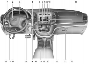
ENGINE COMPARTMENT
G010B01CM-AAT
Gasoline Engine (2.7 V6)
CAUTION:
When inspecting or servicing the engine, you should handle tools and other heavy objects care- fully so that the plastic cover of the engine is not damaged.
1. Coolant reservoir cap 2. Power steering fluid reservoir 3. Engine oil filler cap 4. Brake fluid reservoir
5. Air cleaner 6. Fuse and relay box 7. Windshield washer fluid reservoir 8. Radiator cap
OCM055100L
9. Engine oil level dipstick 10. Automatic transaxle fluid level dipstick
(if installed)
11. Battery
G010C01CM-AAT
Gasoline Engine (3.3 V6)
DO-IT-YOURSELF MAINTENANCE
CAUTION:
When inspecting or servicing the engine, you should handle tools and other heavy objects care- fully so that the plastic cover of the engine is not damaged.
1. Coolant reservoir cap 2. Power steering fluid reservoir 3. Engine oil filler cap 4. Brake fluid reservoir
5. Air cleaner 6. Fuse and relay box 7. Windshield washer fluid reservoir 8. Radiator cap
OCM055102A
9. Engine oil level dipstick 10. Automatic transaxle fluid level dipstick
(if installed)
11. Battery
6 DO-IT-YOURSELF MAINTENANCE
GENERAL CHECKS
G020A01A-AAT
Engine Compartment The following should be checked regu- larly:
o Engine oil level and condition o Transaxle fluid level and condition o Brake fluid level o Clutch fluid level o Engine coolant level o Windshield washer fluid level o Accessory drive belt condition o Engine coolant hose condition o Fluid leaks (on or below components) o Power steering fluid level o Battery condition o Air filter condition
G020B01A-AAT
Vehicle Exterior The following should be checked monthly:
o Overall appearance and condition o Wheel condition and wheel nut torque o Exhaust system condition o Light condition and operation o Windshield glass condition o Wiper blade condition o Paint condition and body corrosion o Fluid leaks o Door and hood lock condition o Tire pressure and condition
(including spare tire)
G020C01A-AAT
Vehicle Interior The following should be checked each time when the vehicle is driven:
o Lights operation o Windshield wiper operation o Horn operation o Defroster, heating system operation
(and air conditioning, if installed) o Steering operation and condition o Mirror condition and operation o Turn signal operation o Accelerator pedal operation o Brake operation, including parking
brake
o Manual transaxle operation, including
clutch operation
o Automatic transaxle operation, includ-
ing "Park" mechanism operation
o Seat control condition and operation o Seat belt condition and operation o Sunvisor operation
If you notice anything that does not operate correctly or appears to be functioning cor- rectly, inspect it carefully and seek assis- tance from your Hyundai dealer if service is needed.
CHECKING THE ENGINE OIL
G030A01A-AAT Engine oil is essential to the performance and service of the engine. It is suggested that you check the oil level at least once a week in normal use and more often if you are on a trip or driving in severe conditions.
G030B01O-AAT
Recommended Oil
NOTE: o For good fuel economy, SAE 5W-20
(5W-30), ILSAC GF-3 engine oil is pre- ferred.o If SAE 5W-20, ILSAC GF-3 engine oil is not available, other recommended en- gine oils for corresponding tempera- ture rangs can be used.
DO-IT-YOURSELF MAINTENANCE
G030C01JM-AAT
To Check the Oil Level
G030B01JM-U The engine oil quality should meet the following classification.
API SJ, SL or ABOVE, ILSAC GF-3 or ABOVE
OCM055002L Before checking the oil, warm up the en- gine to the normal operating temperature and be sure your car is parked on level ground. Turn the engine off. Wait five minutes , then remove the dip- stick, wipe it off, fully reinsert the dipstick and withdraw it again. Then note the high- est level the oil has reached on the dip- stick. It should be between the upper ("F") and lower ("L") range.
! WARNING:
Be very careful not to touch the radiator hose when checking the engine oil as it may be hot enough to burn you.
6 DO-IT-YOURSELF MAINTENANCE
G030D02MC-AAT
Adding Oil
CAUTION:
Slowly pour the recommended oil by using a funnel. Do not overfill so as not to damage engine.
OCM055003L If the oil level is close to or below the "L" mark, add oil until it reaches the "F" mark. To add oil:
1. Remove the oil filler cap by turning it
counterclockwise.
2. Add oil, then check the level again. Do
not overfill.
3. Replace the cap by turning it clockwise.
The distance between the "F" and "L" marks is equal to about 1 quart of oil.
! WARNING:
Be very careful not to touch the radiator hose when adding the engine oil as it may be hot enough to burn you.
NOTE: o It is recommended that the engine oil and filter should be changed by an authorized Hyundai dealer.
o Always dispose of used engine oil in an environmentally acceptable man- ner. It is suggested that it be placed in a sealed container and taken to a service station for reclaimation. Do not pour the oil on the ground or put it into the household trash.
PROPOSITION 65 WARNING: This product contains a chemical known to the State of California to cause can- cer. Used engine oil may cause irritation or cancer of the skin if left in contact with the skin for prolonged periods of time. Used engine oil contains chemicals that have caused cancer in laboratory ani- mals. Always protect your skin by wash- ing your hands thoroughly with soap and warm water as soon as possible after handling used oil.
CHECKING THE ENGINE COOLANT
G050A01TG-AAT
WARNING:
Do not remove the radiator cap when the engine is hot. When the engine is hot, the engine coolant is under pressure and may erupt through the opening if the cap is removed. You could be seriously burned if you do not observe this precau- tion. Do not remove the radiator cap until the radiator is cool to the touch.
NOTE: It is recommended that the engine cool- ant should be changed by an authorized Hyundai dealer.
DO-IT-YOURSELF MAINTENANCE
G050B01A-AAT
Recommended Engine Coolant Use a high quality ethylene-glycol coolant in a 50/50 mix with water. The engine coolant should be compatible with alumi- num engine parts. Additional corrosion inhibitors or additives should not be used. The cooling system must be maintained with the correct concentration and type of engine coolant to prevent freezing and corrosion. Never allow the concentration of antifreeze to exceed the 60% level or go below the 35% level, or damage to the cooling system may result.
For proper concentration when adding or replacing the engine coolant, refer to the following table.
Ambient
Engine Coolant concentration
temperature
°F (°C) 5 (-15) -13 (-25) -31 (-35) -49 (-45)
Antifreeze solution
35% 40% 50% 60%
Water
65% 60% 50% 40%
6 DO-IT-YOURSELF MAINTENANCE
G050C01TG-AAT
To Check the Coolant Level
OCM055004L The coolant level can be seen on the side of the plastic coolant reservoir. The level of the coolant should be between the "L" and "F" lines on the reservoir when the engine is cool. If the level is below the "L" mark, add engine coolant to bring it up between "L" and "F". If the level is low, inspect for coolant leaks and recheck the fluid level frequently. If the level drops again, visit your Hyundai dealer for an inspection and diagnosis of the reason.
CAUTION:
o Engine coolant can damage the finish of your car. If you spill engine coolant on the car, wash it off thoroughly with clean water.
o The engine in your vehicle has alumi- num engine parts and must be pro- tected by an ethylene-glycol base coolant to prevent corrosion and freez- ing. Do not use hard water. Hard water can cause engine damage from corro- sion, overheating or freezing.
! WARNING:
The cooling fan is controlled by engine coolant temperature and may some- times operate even when the engine is not running. Use extreme caution when working near the blades of the cooling fan so that you are not injured by a rotating fan blade. As the engine coolant temperature decreases, the fan will au- tomatically shut off. This is a normal condition.
CHANGING THE AIR CLEANER FILTER
G070A03Y-AAT
OCM055007
The replacement of air cleaner filter is performed in the following manner. 1. Unsnap the clips around the cover. 2. When this is done, the cover can be lifted off, the old filter removed and the new filter put in its place.Genuine Hyundai replacement parts are recommended.
CAUTION:
o Operating your vehicle without a proper air filter in place can result in excessive engine wear.
o When removing the air cleaner filter, be careful that dust or dirt does not enter the air intake. These may result in damage to the air cleaner filter.
WINDSHIELD WIPER BLADES
G080A02A-AAT
G080B02CM-AAT
Replacing the Wiper Blades Front window windshield wiper blades
To remove the wiper blade
DO-IT-YOURSELF MAINTENANCE
OCM055005N The wiper blades should be carefully in- spected from time to time and cleaned to remove accumulations of road film or other debris. To clean the wiper blades and arms, use a clean sponge or cloth with a mild soap or detergent and water. If the wipers continue to streak or smear the glass, replace them with genuine Hyundai replacement parts or their equivalent.
CAUTION:
o Do not operate the wipers on dry glass. This can result in more rapid wear of the wiper blades and may scratch the glass. o Keep the blade rubber out of contact with petroleum products such as en- gine oil, gasoline, etc.
1LDA5023
1. Raise the wiper arm and turn the wiper blade assembly to expose the plastic locking clip.
1JBA7037
1JBA7038
2. Compress the clip and slide the blade
assembly downward.
3. Lift it off the arm.
6 DO-IT-YOURSELF MAINTENANCE 10
To install the wiper blade Install the blade assembly in the reverse order of removal.
Type without wiper arm stopper (if installed)
G080B03CM-AAT
Rear window wiper blade Type with wiper arm stopper (if installed) To prevent damage to the wiper arms or other components, have an authorized Hyundai dealer replace the wiper blade.
CAUTION:
o Do not allow the wiper arm to fall against the windshield, since it may chip or crack the windshield.
o To remove the rear wiper blade, first removes the head cap. If you exces- sively raise the rear wiper arm with the head cap installed, it will damage the head cap.
OCM055017
1. Raise the wiper arm and pull out thewiper blade assembly.
OCM055018
2. Install the new blade assembly by in- serting the center part into the wiper arm until it clicks into place.3. Make sure the blade assembly is in-
4. Place the wiper arm to the proper posi-
stalled firmly.
tion.
FILLING THE WASHER RESERVOIR
G090A01CM-AAT
CAUTION:
o Radiator anti-freeze (engine coolant) should not be used in the washer sys- tem because it will damage the car's finish.
o The washer should not be operated if the washer reservoir is empty. This can damage the washer fluid pump.
OCM055028L The washer fluid reservoir supplies fluid to the front and rear washer systems. A good quality washer fluid should be used to fill the washer reservoir. The fluid level should be checked more frequently during inclement weather or whenever the washer system is in more frequent use.
! WARNING:
o Windshield washer fluid agents con- tain some amounts of alcohol and can be flammable under certain circum- stances. Do not allow sparks or flame to contact the washer fluid or the washer fluid reservoir. Damage to the vehicle or its occupants could occur.
o Windshield washer fluid is poisonous to humans and animals. Do not drink windshield washer fluid. Serious in- jury or death could occur.
11
DO-IT-YOURSELF MAINTENANCE
CHECKING THE TRANSAXLE OIL (MANUAL)
G100A01MC-GAT Transaxle lubricant in the manual transaxle should be checked at those intervals speci- fied in the vehicle maintenance schedule in Section 5.
! WARNING:
It is always better to check the transaxle oil level when the engine is cool or cold. If the engine is hot, you should exercise great caution to avoid burning yourself on hot engine or exhaust parts.
NOTE: It is recommended that the manual transaxle fluid should be checked by an authorized Hyundai dealer.
6 DO-IT-YOURSELF MAINTENANCE 12
CHECKING THE TRANSAXLE FLUID (AUTOMATIC)
G110A01MC-AAT Transaxle fluid in the automatic transaxle should be checked at those intervals speci- fied in the vehicle maintenance schedule in Section 5.
NOTE: Automatic transaxle fluid is basically a red color. As driving distance increases, the fluid color turns darkish red gradu- ally. It is a normal condition and you should not judge the need to replace based upon the changing color. You must replace the automatic transaxle fluid in accordance with inter- vals specified in the vehicle maintenance schedule in section 5.
G110D02CM-AAT
To Check the Transaxle Fluid Level
OCM055006
The automatic transaxle fluid level should be checked regularly.CAUTION:
Use of aftermarket ATF additives may cause damage to the automatic transaxle. Only use HYUNDAI GENUINE ATF SP III, DIAMOND ATF SP III, SK ATF SP III or other brands meeting the SP III specifi- cation approved by Hyundai Motor Co.. If you are having your vehicle serviced at a facility other than a Hyundai dealer, verify that the correct ATF is used for your vehicle.
! WARNING:
The transaxle fluid level should be checked when the engine is at normal operating temperature. This means that the engine, radiator, exhaust system etc., are very hot. Exercise great care not to burn yourself during this proce- dure.
DO-IT-YOURSELF MAINTENANCE
13
! WARNING:
The cooling fan is controlled by engine coolant temperature and may some- times operate even when the engine is not running. Use extreme caution when working near the blades of the cooling fan, so that you are not injured by a rotating fan blade. As the engine coolant temperature decreases, the fan will au- tomatically shut off. This is a normal condition.
Keep the vehicle on level ground with the parking brake applied and check the fluid level according to the following proce- dure.
1. Place the shift lever in N(neutral) posi- tion and confirm the engine is running at normal idle speed.
2. After the transaxle is warmed up suffi- ciently [fluid temperature 70~80°C (158~176°F)], for example by 10 min- utes usual driving, move the shift lever through all positions then place the shift lever in N(neutral) or P(park) position.
Fluid level should be within 75°C range
OCM055037L
3. Confirm if the fluid level is in the “75°C” range on the level gauge. If the fluid level is lower, add the specified fluid from the fill hole. If the fluid level is higher, drain the fluid from the drain hole.
4. If the fluid level is checked in cold condition[fluid temperature 20~30°C (68~86°F)], add the fluid to the “25°C” line and then recheck the fluid level according to the above step 2.
6 DO-IT-YOURSELF MAINTENANCE 14
CHECKING THE BRAKES
G120A01A-AAT
CAUTION:
Because brakes are essential to the safe operation of the car, it is suggested that they be checked and inspected by your Hyundai dealer. The brakes should be checked and inspected for wear at those intervals specified in the vehicle maintenance schedule in Section 5.
G120B01A-AAT
Checking the Brake Fluid Level
WARNING:
Use caution when handling brake fluid. It can damage your vision if it gets into your eyes. It will also damage your vehicle's paint if spilled on it and not removed immediately.
G120C02A-AAT
Recommended Brake Fluid Use only hydraulic brake fluid conforming to DOT 3 or DOT 4 specifications in your braking system. Follow the instructions printed on the container.
G120D01CM-AAT
To Check the Fluid Level
OCM055014
It is normal for the brake fluid level to go down slightly as the brake pads wear. The fluid level in the brake fluid reservoir should be checked periodically. The level should be between the "MIN" and "MAX" marks on the side of the reservoir. If the level is at or below the "MIN" mark, care- fully add fluid to bring it up to "MAX".G120E02A-AAT
Adding Brake Fluid
WARNING:
Handle brake fluid carefully. It can dam- age your vision if it gets into your eyes. Use only DOT 3 or DOT 4 specification fluid from a sealed container. Do not allow the fluid can or reservoir to remain open any longer than required. This will prevent entry of dirt and moisture which can damage the brake system and cause improper operation.
To add brake fluid, first wipe away any dirt then unscrew the fluid reservoir cap. Slowly pour the recommended fluid into the res- ervoir. Do not overfill. Carefully replace the cap on the reservoir and tighten.
AIR CONDITIONING CARE
DO-IT-YOURSELF MAINTENANCE
15
G140A01A-AAT
Keeping the Condenser Clean The air conditioning condenser (and en- gine radiator) should be checked periodi- cally for accumulation of dirt, dead insects, leaves, etc. These can interfere with maxi- mum cooling efficiency. When removing such accumulations, brush or hose them away carefully to avoid bending the cool- ing fins.
G140B01A-AAT
Checking the Air Conditioning Operation 1. Start the engine and let it run at a fast idle for several minutes with the air condi- tioning set at the maximum cold setting. 2. If the air coming out of the in-dash vents is not cold, have the air conditioning system inspected by your Hyundai dealer.
CAUTION:
Running the air conditioning system for extended periods of time with a low re- frigerant level may damage the com- pressor.
G140C01A-AAT
Lubrication To lubricate the compressor and the seals in the system, the air conditioning should be run for at least 10 minutes each week. This is particularly important during cool weather when the air conditioning system is not otherwise in use.
6 DO-IT-YOURSELF MAINTENANCE 16
CHANGING THE CLIMATE CONTROL AIR FILTER
B145A01CM-AAT
(For Evaporator and Blower Unit) (If Installed) The climate control air filter is located in front of the evaporator unit behind the glove box. It helps to decrease the amount of pollut- ants entering the car.
OCM055010
1. Open the glove box and remove the adjusting pins on both sides of the glove box.
OCM055009
2. Pull the damper strap on the right sideof the glove box through the hole.
3. Lower down the glove box completely.
OCM055011
4. Pull out the climate control air filter withthe hooks on both sides pressed.
CAUTION:
Be careful not to press the hooks in the opposite direction.
DO-IT-YOURSELF MAINTENANCE
CHECKING AND REPLACING FUSES
G200A03A-AAT
Replacing a Fusible Link
17
CHECKING PARKING BRAKE PEDAL
G185A02TG-GAT
(If Installed) The parking brake pedal should be checked periodically for proper stroke. If you feel looseness in the parking brake pedal when the parking brake is engaged, have your parking brake adjusted by an authorized Hyundai dealer.
CAUTION:
If the parking brake pedal is not adjusted properly, the vehicle may roll backwards when parking on a steep hill.
OCM054003
A fusible link will melt if the electrical cir- cuits from the battery are ever overloaded, thus preventing damage to the entire wir- ing harness. (This could be caused by a short in the system drawing too much cur- rent.) If this ever happens, have a Hyundai dealer determine the cause, repair the system and replace the fusible link. The fusible links are located in a relay box in the engine compartement for easy inspection.HNF2165
5. Replace the air conditioner filter by lift-
6. Installation is the reverse order of disas-
ing it.
sembly.
CAUTION:
To prevent pollutants from entering the car, be sure to properly install the air conditioner filter.
6 DO-IT-YOURSELF MAINTENANCE 18
CAUTION:
When replacing a fusible link, never use anything but a new fusible link with the same or lower amperage rating. Never use a piece of wire or a higher-rated fusible link. This could result in serious damage and create a fire hazard.
G200B02HP-AAT
Replacing Accessory Fuses
OCM054002
The fuse box for the lights and other elec- trical accessories will be found low on the dashboard on the driver's side. Inside the box you will find a list showing the circuits protected by each fuse. If any of your car's lights or other electrical accessories stop working, a blown(open) fuse could be the reason. If the fuse has burned out, you will see that the metal strip inside the fuse has melted through. If you suspect a blown fuse, follow this proce- dure:1. Turn off the ignition and all other
switches.
2. Open the fuse box and examine each fuse. Remove each fuse by pulling it toward you (a small "fuse puller" tool is contained in the relay and fuse box of the engine room to simplify this opera- tion).
3. Be sure to check all other fuses even if you find one that appears to have burned out.
DO-IT-YOURSELF MAINTENANCE
19
CAUTION:
A burned-out fuse indicates that there is a problem in the electrical circuit. If you replace a fuse and it blows as soon as the accessory is turned on, the problem is serious and should be referred to a Hyundai dealer for diagnosis and repair. Never replace a fuse with anything ex- cept a fuse with the same or a lower amperage rating. A higher capacity fuse could cause damage and create a fire hazard.
Good
Burned out
NOTE: See page 6-32 for the fuse panel descrip- tions.
1VQA4037
G200B02NF 4. Replace the blown fuse by pressing a new fuse of the same rating into place. The fuse should be a snug fit. If it is not, have the fuse clip repaired or replaced by a Hyundai dealer. If you do not have a spare fuse, you may be able to borrow a fuse of the same or lower rating from an accessory you can temporarily get along without (the radio or cigarette lighter, for example). Always remember to replace the borrowed fuse.
6 DO-IT-YOURSELF MAINTENANCE 20
G200C01CM-GAT
Power connector
OCM055026L
Your vehicle is equipped with a power connector to prevent battery discharge if your vehicle is parked without being oper- ated for prolonged periods. Use the follow- ing procedures before parking the vehicle for prolonged periods.
1. Turn off the engine. 2. Turn off the headlights and tail lights. 3. Open the driver’s side panel cover and
pull out the power connector.
4. Insert the power connector in the oppo-
site direction.
NOTE: o If the power connector is pulled out of the fuse panel, the warning chime, audio, clock and interior lamps, etc., will not operate. The following items must be reset after replacement. - Digital Clock - Trip computer - Automatic heating and cooling con-
trol system
- Audio
o Even though the power connector is pulled out, the battery can still be discharged by operation of the head- lights or other electrical devices.
CHECKING THE BATTERY
G210A01A-AAT
OCM055016
WARNING:
Batteries can be dangerous! When work- ing with batteries, carefully observe the following precautions to avoid serious injuries.
The fluid in the battery contains a strong solution of sulfuric acid, which is poison- ous and highly corrosive. Be careful not to spill it on yourself or the car. If you do spill battery fluid on yourself, immediately do the following:
o If battery fluid is on your skin, flush the affected areas with water for at least 15
minutes and then seek medical assis- tance.o If battery fluid is in your eyes, rinse out your eyes with water and get medical assistance as soon as possible. While you are being driven to get medical assistance, continue to rinse your eyes by using a sponge or soft cloth satu- rated with water.
o If you swallow battery fluid, drink a large quantity of water or milk followed by milk of magnesia, eat a raw egg or drink vegetable oil. Get medical assistance as soon as possible.
While batteries are being charged (either by a battery charger or by the vehicle's generator), they produce explosive gases. Always observe these warnings to prevent injuries from occurring:
o Charge batteries only in a well venti-
o Do not permit flames, sparks or smok-
lated area.
ing in the area.
o Keep children away from the area.
G210B04A-AAT
Checking the Battery Keep the battery clean. Any evidence of corrosion around the battery posts or ter- minals should be removed using a solu- tion of household baking soda and warm water. After the battery terminals are dry, cover them with a light coating of grease.
PROPOSITION 65 WARNING: Battery posts, terminals, and related accessories contain lead and lead com- pounds, chemicals known to the state of California to cause cancer and repro- ductive harm. Batteries also contain other chemicals known to the state of California to cause cancer. Wash hands after handling.
DO-IT-YOURSELF MAINTENANCE
21
WARNING: Always read the following in- structions carefully when han- dling a battery. Keep lighted cigarettes and all other flames or sparks away from the battery. Hydrogen, which is a highly combustible gas, is always present in battery cells and may explode if ignited. Keep batteries out of the reach of children because batteries contain highly corrosive SUL- FURIC ACID. Do not allow bat- tery acid to contact your skin, eyes, clothing or paint finish. If any electrolyte gets into your eyes, flush your eyes with clean water for at least 15 min- utes and get immediate medi- cal attention. If possible, con- tinue to apply water with a sponge or cloth until medical attention is received.
6 DO-IT-YOURSELF MAINTENANCE 22
CHECKING ELECTRIC COOLING FANS
G220A01A-AAT
WARNING:
The cooling fan is controlled by engine coolant temperature and may some- times operate even when the engine is not running. Use extreme caution when working near the blades of the cooling fan, so that you are not injured by a rotating fan blade. As the engine coolant temperature decreases the fan will au- tomatically shut off. This is a normal condition.
! WARNING:
If electrolyte gets on your skin, thoroughly wash the contacted area. If you feel a pain or a burning sensation, get medical atten- tion immediately. Wear eye protection when charging or working near a bat- tery. Always provide ventilation when working in an enclosed space.
o When lifting a plastic-cased battery, excessive pressure on the case may cause battery acid to leak, resulting in personal injury. Lift with a battery carrier or with your hands on opposite corners.
o Never attempt to charge the battery when the battery cables are con- nected.
o The electrical ignition system works
with high voltage. Never touch these components with the engine running or the ignition switched on.
G220B01A-AAT
Checking Engine Cooling Fan The engine cooling fan should come on automatically if the engine coolant tem- perature is high.
G220C01A-AAT
Checking Condenser Cooling Fan The condenser cooling fan should come on automatically whenever the air condi- tioning is in operation.
POWER STEERING FLUID LEVEL
G230A01MC-AAT
23
DO-IT-YOURSELF MAINTENANCE
FOR MORE INFORMATION ABOUT YOUR HYUNDAI
G250A01A-AAT If you desire additional information about maintaining and servicing your Hyundai, you may purchase a factory Shop Manual at your Hyundai dealer's parts department. This is the same manual used by dealer- ship technicians and while it is highly tech- nical it can be useful in obtaining a better understanding of your car and how it works.
NOTE: o Grinding noise from the power steer- ing pump may be heard immediately after the engine is started in extremely cold conditions (below - 4°F). If the noise stops during warm up, there is no abnormal function in the system. It is due to a power steering fluid char- acteristic in extremely cold condi- tions.
o Do not start the engine when the power
steering oil reservoir is empty.
OCM055027L
The power steering fluid level should be checked regularly. To check the power steering fluid level, be sure the engine is "OFF", then check to make certain that the power steering fluid level is between the "MAX" and "MIN" level markings on the fluid reservoir.
G240A01A-AAT
Power Steering Hoses It is suggested that you check the power steering hose connections for fluid leak- age at those intervals specified in the ve- hicle maintenance schedule in Section 5. The power steering hoses should be re- placed if there is severe surface cracking, pulling, scuffing or worn spots. Deteriora- tion of the hose could cause premature failure.
6 DO-IT-YOURSELF MAINTENANCE 24
REPLACEMENT OF LIGHT BULBS
G260A01CM-AAT Before attempting to replace a light bulb, be sure the switch is turned to the "OFF" position. The next paragraph shows how to reach the light bulbs so they may be changed. Be sure to replace the burned-out bulb with one of the same number and wattage rating.
CAUTION:
o Keep the lamps out of contact with petroleum products, such as oil, gaso- line, etc.
o After heavy, driving rain or washing, headlight and taillight lenses could appear frosty. This condition is caused by the temperature difference between the lamp inside and outside. This is similar to the condensation on your windows inside your vehicle during the rain and doesn’t indicate a problem with your vehicle. If the water leaks into the lamp bulb circuitry, have the vehicle checked by an Authorized Hyundai Dealer.
G270A01CM-GAT
Headlight, Front Turn Signal Light and Front Position Light
(1)
(2)
(3)
(4)
(5)
OCM055020
(1) Turn signal light/Side marker (2) Front position light (3) Headlight (Low Beam) (4) Headlight (High Beam) (5) Front fog light
1. Allow the bulb to cool. Wear eye pro-
tection.
2. Open the engine hood. 3. Always grasp the bulb by its plastic
base, avoid touching the glass.
OCM055008L
OCM055021L 4. Using a wrench, remove the headlight
assembly mounting bolts and nut.
DO-IT-YOURSELF MAINTENANCE
25
OCM055012L
8. Push the bulb spring to remove the
headlight bulb.
9. Remove the protective cap from the replacement bulb and install the new bulb by matching the plastic base with the headlight hole. Reattach the bulb spring and reconnect the connector. 10. Use the protective cap and carton to
promptly dispose of the old bulb. 11. Check for proper headlight aim.
OCM055009L 5. Disconnect the wire harness from the bulb base in the back of the headlight.
OCM055011L 7. Disconnect the connector from the bulb
base in the back of the headlight.
6. Turn the plastic cover counterclock-
wise and remove it.
OCM055010L
6 DO-IT-YOURSELF MAINTENANCE 26
G270K01CM-GAT
Front Fog Light (If Installed) NOTE: It is recommended that the front fog light bulb be replaced by an authorized Hyundai dealer.
OCM055014L
G270A03O
12. To replace the front turn signal light bulb or the front position light bulb, take it out from the bulb holder and install the new bulb.
! WARNING:
This halogen bulb contains gas under pressure and if impacted could shatter, resulting in flying fragments. Always wear eye protection when servicing the bulb. Protect the bulb against abrasions or scratches and against liquids when lighted. Turn the bulb on only when in- stalling in a headlight. Replace the head- light if damaged or cracked. Keep the bulb out of the reach of children and dispose of the used bulb with care.
G270B01CM-AAT
Rear Combination Light
(3)
(1)
(2)
OCM055022
(1)Stop/Tail light (2)Back-up light (3)Turn signal light/Side marker 1. Open the tail gate.
DO-IT-YOURSELF MAINTENANCE
27
OCM052016
(3)
(1)
OCM055026
(2)
(1)
OCM055028
OCM055030
2. Remove the cover with a flat-head
screwdriver.
3. Remove the mounting screws of the rear combination light as shown in the photo.
(1) Stop/Tail light (2) Back-up light (3) Turn signal light/Side marker 4. To replace the rear combination light, take it out from the bulb holder by turning it counterclockwise.
5. Install the new bulb.
6 DO-IT-YOURSELF MAINTENANCE 28
G270I01CM-GAT
High Mounted Rear Stop Light (If Installed)
G270J01CM-AAT
License Plate Light
G270E01CM-AAT
Side Repeater Light (If installed)
OCM055027
NOTE: It is recommended that the High-Mounted Rear Stop Light be replaced by an autho- rized Hyundai Dealer.
OCM055036
1. Remove the mounting screws of the license plate light cover with a phillips screwdriver.2. Disconnect the wire harness by turning the bulb cover counterclockwise and take the bulb out from the bulb cover by turning it clockwise.
3. Replace with a new bulb.
OEN076031
NOTE: If the light bulb is not operating, have the vehicle checked by an authorized HYUNDAI dealer.
G270G01O-GAT
Interior Light (If installed)
DO-IT-YOURSELF MAINTENANCE
29
1. Remove the cover with a flat-head
screwdriver.
2. Replace with a new bulb.
OCM055016A
OCM055033
OCM055032A
OCM055034
6 DO-IT-YOURSELF MAINTENANCE 30
G270C02TB-AAT
Luggage Compartment Light (If Installed)
G270C02JM-AAT
Cargo Light
G270H01CM-AAT
Glove Box Light
OCM055035
OCM055017L
OCM066039A
1. Remove the cover with a flat blade
screw driver.
2. Disconnect the wire harness. 3. Replace with a new bulb.
1. Open the tail gate. 2. Remove the cover with a flat-head
1. Open the glove box. 2. Remove the cover with a flat-head
screwdriver.
3. Replace with a new bulb.
screwdriver.
3. Disconnect the connector. 4. Replace with a new bulb.
BULB WATTAGE
G280A02CM-AAT
DO-IT-YOURSELF MAINTENANCE
31
No.
Part Name
Wattage
Socket Type
Glove Box Light
Headlight (Low/High)
Turn Signal Light/Side Marker
Map Light
Interior Light
Front Fog Light (If installed)
Front Position Light
Side Repeater Light (If installed)
55
27
10
10
27
No.
10
11
12
S8.5/8.5
PX26D
BAY15D
W2.1 x 9.5D
S8.5/8.5
PG13
W2.1 x 9.5D
Rear Combination Light
Turn Signal Light
Stop/Tail Light
Back-up Light
LED
13
License Plate Light
OCM058025M
Part Name
Wattage
Socket Type
Front Door Edge Warning Light (If installed)
Luggage Compartment Light (If installed)
High Mounted Rear Stop Light (If installed)
10
16
W2.1 x 4.6D
S8.5/8.5
W2.1 x 9.5D
27
27/8
16
BAU15s
BAY15D
W2.1 x 9.5D
W2.1 x 9.5D
6 DO-IT-YOURSELF MAINTENANCE 32
FUSE PANEL DESCRIPTION
G200C01CM-AAT
Engine Compartment
FUSE ALT
A/CON RR HTD
BLR BATT P/WDW
ESC #1
ESC #2
DEICER ECU MAIN
HORN IG COIL
SENSOR #3
RAD FAN CON FAN
SENSOR #2
SENSOR #1
FUSE RATING
CIRCUIT PROTECTED
150A 10A 30A 40A 50A 40A
40A
20A
15A 40A 15A 20A
15A
40A 30A
15A
10A
GENERATOR A/CON RELAY RR HTD RELAY I/PJUNCTION BOX I/PJUNCTION BOX I/PJUNCTION BOX ABS CONTROL MODULE, ESC CONTROL MODULE, MULTIPURPOSE CHECK CONNECTOR ABS CONTROL MODULE, ESC CONTROL MODULE, MULTIPURPOSE CHECK CONNECTOR DEICER RELAY ENGINE CONTROL RELAY HORN RELAY IGNITION COIL #1~#6(GASOLINE), CONDENSOR(GASOLINE) PURGE CONTROL SOLENOID VALVE(GASOLINE), VARIABLE INTAKE MANIFOLD VALVE(GASOLINE), PCM(GASOLINE), OIL CONTROL VALVE(GASOLINE) RAD FAN RELAY CON FAN #1 RELAY, CON FAN #2 RELAY MASS AIR FLOW SENSOR(GASOLINE), OXYGEN SENSOR #1~#4(GASOLINE), PCM(GASOLINE) IMMOBILIZER MODULE, INJECTOR #1~#6(GASOLINE), PCM(GASOLINE), A/ CON RELAY, FUEL PUMP RELAY
OCM055023N
Note: Not all fuse panel descriptions in this manual may be applicable to your vehicle. It is accurate at the time of printing. When you inspect the fuse box on your vehicle, refer to the fuse box label.
DO-IT-YOURSELF MAINTENANCE
33
FUSE
FUSE RATING
CIRCUIT PROTECTED
FUEL PUMP H/LP LO LH H/LP LO RH
FR FOG
H/LP
FR WIPER
H/LP HI
H/LP HI IND
IGN #1
IGN #2
BATT ATM TCUALT DSL
ECU
COOLING B/UP UP
ESC
TAIL LH
TAIL RH
SPARE SPARE SPARE SPARE SPARE
15A 15A 15A 10A 10A 25A 20A 10A 40A 40A 50A 20A 15A 10A 10A 10A 10A
10A
10A
10A
10A