- 2011 Hyundai Accent Owners Manuals
- Hyundai Accent Owners Manuals
- 2005 Hyundai Accent Owners Manuals
- Hyundai Accent Owners Manuals
- 2003 Hyundai Accent Owners Manuals
- Hyundai Accent Owners Manuals
- 2009 Hyundai Accent Owners Manuals
- Hyundai Accent Owners Manuals
- 2008 Hyundai Accent Owners Manuals
- Hyundai Accent Owners Manuals
- 2004 Hyundai Accent Owners Manuals
- Hyundai Accent Owners Manuals
- 2007 Hyundai Accent Owners Manuals
- Hyundai Accent Owners Manuals
- 2012 Hyundai Accent Owners Manuals
- Hyundai Accent Owners Manuals
- Download PDF Manual
-
- Knee Bolster - Pre-tensioner seat belt - Front impact sensors - Driver's and front passenger's seat belt usage
- Driver's and front passenger's seat position
sensors
sensors
- SRS Service Reminder Indicator (SRI) - SRS Control Module (SRSCM)
Upon deployment, tear seams molded directly into the pad covers will separate under pres- sure from the expansion of the airbags. Fur- ther opening of the covers then allows full inflation of the airbags.
The SRSCM continually monitors all elements while the ignition is "ON" to determine if a frontal or near-frontal impact is severe enough to re- quire airbag deployment.
The SRS service reminder indicator (SRI) on the instrument panel will blink for about 6
seconds after the ignition key is turned to the "ON" position or after the engine is started, after which the SRI should go out. The airbag modules are located both in the center of the steering wheel and in the front passenger's panel above the glove box. When the SRSCM detects a considerable impact to the front of the vehicle, it will automatically deploy the airbags.B240B03L A fully inflated airbag in combination with a properly worn seat belt slows the driver's or the passenger's forward motion, thus reduc- ing the risk of head and chest injury.
After complete inflation, the airbag immediately starts deflating, enabling the driver to maintain forward visibility.
B240B02L
Passenger's Airbag
Passenger's Airbag
B240B01A
B240B05L
CAUTION:
When installing a container of liquid air freshener inside the vehicle, do not place it near the instrument cluster nor on the in- strument panel surface. If there is any leak- age from the air freshener onto these areas (instrument cluster, instrument panel or air ventilator), it may damage these parts. If the liquid from the air freshener does leak onto these areas, wash them with water immedi- ately.
WARNING:
o When the SRS is activated, there may be a loud noise and fine dust will be released throughout the vehicle. These conditions are normal and are not haz- ardous. However, the fine dust gener- ated during airbag deployment may cause skin irritation. Wash your hands and face thoroughly with lukewarm wa- ter and a mild soap after an accident in which the airbags were deployed.
FEATURES OF YOUR HYUNDAI
33
WARNING:
o The SRS can function only when the ignition key is in the "ON" position. If the SRS SRI does not illuminate, or continuously remains on, after flashing for about 6 seconds when the ignition key is turned to the "ON" position, or after the engine is started, comes on while driving, the SRS is not working properly. If this occurs, have your vehi- cle immediately inspected by your Hyundai dealer.
o Before you replace a fuse or disconnect a battery terminal, turn the ignition key to the "LOCK" position or remove the ignition key. Never remove or replace the air bag related fuse(s) when the ignition key is in the "ON" position. Failure to heed this warning will cause the SRS SRI to illuminate.
1FEATURES OF YOUR HYUNDAI 34
B990B04Y-GAT Side Impact Airbag (If Installed)
Side airbag sensor
B990B01A-1
B990B02Y
Your Hyundai is equipped with a side impact airbag in each front seat. The purpose of the airbag is to provide the vehicle's driver and/or the front passenger with additional protection than that offered by the seat belt alone. The side impact airbags are designed to deploy only during certain side impact collisions, depending on the crash severity, angle, speed and point of impact. The side impact airbags are not de- signed to deploy in all side impact situations.
WARNING:
o The side impact airbag is supplemental to the driver's and the passenger's three point seat belt systems and is not a sub- stitute for them. Therefore your seat belts must be worn at all times while the ve- hicle is in motion. The airbags deploy only in certain side impact conditions severe enough to cause significant injury to the vehicle occupants.
WARNING:
o For best protection from the side im- pact airbag system and to avoid being injured by the deploying side impact airbag, both front seat occupants should sit in an upright position with the seat belt properly fastened. The driver's hands should be placed on the steering wheel at the 9:00 and 3:00
o'clock positions. The passenger's arms and hands should be placed on their laps.o Do not use any accessory seat covers. o Use of seat covers could reduce or pre-
vent the effectiveness of the system.
o Do not install any accessories on the side
or near the side impact airbag.
o Do not use excessive force on the side of
the seat.
o Do not place any objects over the airbag
or between the airbag and yourself.
o Do not place any objects (an umbrella, bag, etc.) between the front door and the front seat. Such objects may become dan- gerous projectiles and cause injury if the supplemental side impact airbag inflates.
!
WARNING:
o To prevent unexpected deployment of the side impact air bag that may result in personal injury, avoid impact to the side impact airbag sensor when the ignition key is on.
B240C03A-AAT SRS Care
o The SRS is virtually maintenance free and there are no parts you can safely service by yourself. The entire SRS system must be inspected by an authorized Hyundai dealer in 10 years after the date that the vehicle was manufactured. o Any work on the SRS system, such as remov- ing, installing, repairing, or any work on the steering wheel must be performed by a qualified Hyundai technician. Improper handling of the airbag system may result in serious personal injury.
B240C01HP
WARNING:
o Do not install a child restraint system in
the front passenger seat position. A child restraint system must never be placed in the front seat. The infant or baby could be severely injured by an airbag deployment in case of an acci- dent.
o Modification to SRS components or wir-ing, including the addition of any kind of badges to the pad covers or modifications to the body structure, can adversely affect SRS performance and lead to possible injury.
FEATURES OF YOUR HYUNDAI
35
o For cleaning the airbag pad covers, use only a soft, dry cloth or one which has been moistened with plain water. Sol- vents or cleaners could adversely affect the airbag covers and proper deployment of the system.
o No objects should be placed over or near the airbag modules on the steer- ing wheel, instrument panel, and the front passenger's panel above the glove box, because any such object could cause harm if the vehicle is in a crash severe enough to cause the airbags to inflate.
o If the airbags inflate, they must be replaced by an authorized Hyundai dealer.
o Do not tamper with or disconnect SRS wiring, or other components of the SRS system. Doing so could result in injury, due to accidental inflation of the airbags or by rendering the SRS inoperative.
o If components of the airbag system must be discarded, or if the vehicle must be scrapped, certain safety pre- cautions must be observed. Your Hyundai dealer knows these precau- tions and can give you the necessary information. Failure to follow these precautions and procedures could in- crease the risk of personal injury.
1FEATURES OF YOUR HYUNDAI 36
WARNING:
o If you sell your vehicle, be sure to inform the new owner of these impor- tant points and make certain that this manual is transferred to the new owner. o If your car was flooded and has soaked carpeting or water on the floor, you shouldn't try to start the engine; have the car towed to an authorized Hyundai dealer.
B240D01JM-AAT Additional Safety Precautions
o Never let passengers ride in the cargo area (trunk) or on top of a folded-down back seat. All occupants should sit upright, fully back in their seats with their seat belts on and their feet on the floor.
o Passengers should not move out of or change seats while the vehicle is mov- ing. A passenger who is not wearing a seat belt during a crash or emergency stop can be thrown against the inside of the vehicle, against other occupants, or out of the vehicle.
o Each seat belt is designed to restrain one occupant. If more than one person uses the same seat belt, they could be seriously injured or killed in a collision.
o Do not use any accessories on seat belts. Devices claiming to improve occu- pant comfort or reposition the seat belt can reduce the protection provided by the seat belt and increase the chance of serious injury in a crash.
o Passengers should not place hard or sharp objects between themselves and the airbags. Carrying hard or sharp ob- jects on your lap or in your mouth can result in injuries if an airbag inflates.
o Keep occupants away from the airbag covers. All occupants should sit upright, fully back in their seats with their seat belts on and their feet on the floor. If occupants are too close to the airbag covers, they could be injured if the airbags inflate.
o Do not attach or place objects on or near the airbag covers. Any object at- tached to or placed on the front or side impact airbag covers could interfere with the proper operation of the airbags.
o Do not modify the front seats. Modifica- tion of the front seats could interfere with the operation of the supplemental restraint system sensing components or side im- pact airbags.
o Do not place items under the front seats. Placing items under the front seats could interfere with the operation of the supplemental restraint system sensing components and wiring harnesses.
o Never hold an infant or child on your lap. The infant or child could be seriously injured or killed in the event of a crash. All infants and children should be properly restrained in appropriate child safety seats or seat belts in the rear seat.
WARNING:
o Sitting improperly or out of position can result in serious injury or death in a crash.
o Always sit upright, fully back in the seat, with your seat belt on, and your feet on the floor.
Adding Equipment to or Modifying Your Airbag-Equipped Vehicle.
If you modify your vehicle by changing your vehicle's frame, bumper system, front end or side sheet metal or ride height, this may affect the operation of your vehicle's airbag system.
INSTRUMENT CLUSTER AND INDICATOR LIGHTS
B260A03A-AAT
FEATURES OF YOUR HYUNDAI
37
10
11
12
13
14
15
16 17 18
19
B260A02A-A
1FEATURES OF YOUR HYUNDAI 38
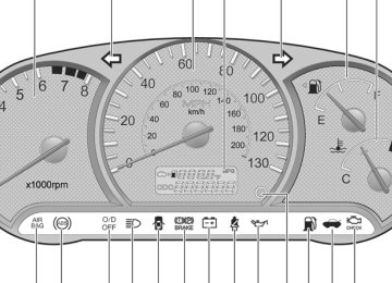
1. Tachometer (If Installed) 2. Turn Signal Indicator Light 3. Speedometer 4. Odometer / Trip Odometer / Trip Computer (If Installed) 5. Fuel Gauge 6. Temperature Gauge 7. SRS Service Reminder Indicator 8. ABS Service Reminder Indicator (If Installed) 9. Overdrive Off Indicator Light (If Installed) 10. High Beam Indicator Light
11. Door Ajar Warning Light 12. Parking Brake/Low Brake fluid Level Warning Light 13. Charging System Warning Light 14. Seat Belt Warning Light 15. Low Oil Pressure Warning Light 16. Trip Odometer Reset Switch /
Trip Computer Reset Switch (If Installed)
17. Low Fuel Warning Light 18. Trunk Lid/Tail Gate Open Warning Light 19. Malfunction Indicator Light (MIL)
WARNING AND INDICATOR LIGHTS
FEATURES OF YOUR HYUNDAI
39
B260B01A-AAT
B260P02Y-GAT
B260C01A-AAT
SRS (AIRBAG) SERVICE RE- MINDER INDICATOR (SRI)
ABS SERVICE REMINDER IN- DICATOR (SRI) (If Installed)
O/D OFF INDICATOR (Automatic Transaxle only)
The SRS service reminder indicator (SRI) comes on and flashes for about 6 seconds after the ignition key is turned to the "ON" position or after the engine is started, after which it will go out.
This light also comes on when the SRS is not working properly. If the SRI does not come on, or continuously remains on after flashing for about 6 seconds when you turned the ignition key to the "ON" position or started the engine, or if it comes on while driving, have the SRS inspected by an authorized Hyundai Dealer.
When the key is turned to the "ON" position, the Anti-Lock Brake System SRI will come on and then go off in a few seconds. If the ABS SRI remains on, comes on while driving, or does not come on when the key is turned to the "ON" position, this indicates that there may be a problem with the ABS. If this occurs, have your vehicle checked by your Hyundai dealer as soon as possible. The normal braking system will still be operational, but without the assistance of the anti-lock brake system.
WARNING:
If both ABS SRI and Parking Brake/Brake fluid level warning lights remain "ON" or come on while driving, there may be a problem with E.B.D. (Electronic Brake Force Distribution). If this occurs, avoid sudden stops and have your vehicle checked by your Hyundai dealer as soon as possible.
When the overdrive switch is turned on, the overdrive off indicator will go out. This amber indicator will be illuminated when the overdrive switch is turned off (Auto T/A only).
B260D01A-AAT
TURN SIGNAL INDICATOR LIGHTS
The blinking green arrow on the instrument panel shows the direction indicated by the turn signals. If the arrow comes on but does not blink, blinks more rapidly than normal, or does not blink at all, a malfunction in the turn signal system is indicated. Your dealer should be con- sulted for repairs.
B260F01A-AAT
HIGH BEAM INDICATOR LIGHT
The high beam indicator light comes on when- ever the headlights are switched to the high beam or flash position.
1FEATURES OF YOUR HYUNDAI 40
B260G01A-AAT
B260H03A-AAT
LOW OIL PRESSURE WARNING LIGHT
PARKING BRAKE/ LOW BRAKE FLUID LEVEL WARNING LIGHT
CAUTION:
If the oil pressure warning light stays on while the engine is running, serious engine damage may result. The oil pressure warning light comes on whenever there is insufficient oil pressure. In normal operation, it should come on when the ignition switch is turned on, then go out when the engine is started. If the oil pressure warning light stays on while the engine is running, there is a serious malfunc- tion. If this happens, stop the car as soon as it is safe to do so, turn off the engine and check the oil level. If the oil level is low, fill the engine oil to the proper level and start the engine again. If the light stays on with the engine running, turn the engine off immediately. In any in- stance where the oil light stays on when the engine is running, the engine should be checked by a Hyundai dealer before the car is driven again.
CAUTION:
If you suspect brake trouble, have your brakes checked by a Hyundai dealer as soon as pos- sible. Driving your car with a problem in either the brake electrical system or brake hydraulic system is dangerous, and could result in se- rious injury or death.
Warning Light Operation
The parking brake/brake fluid level warning light should come on when the parking brake is applied and the ignition switch is turned to "ON" or "START". After the engine is started, the light should go out when the parking brake is re- leased. If the parking brake is not applied, the warning light should come on when the ignition switch is turned to "ON" or "START", then go out when the engine starts. If the light comes on at any other time, you should slow the vehicle and bring it to a complete stop in a safe location off the roadway.
The brake fluid level warning light indicates that the brake fluid level in the brake master cylinder is low and brake fluid conforming to DOT 3 or DOT 4 specifications should be added. After adding fluid, if no other trouble is found, the car should be immediately and carefully driven to a Hyundai dealer for inspection. If further trouble is experienced, the vehicle should not be driven at all but taken to a dealer by a professional towing service. Your Hyundai is equipped with dual-diagonal braking systems. This means you still have braking on two wheels even if one of the dual systems should fail. With only one of the dual systems working, more than normal pedal travel and greater pedal pressure are required to stop the car. Also, the car will not stop in as short a distance with only a portion of the brake system working. If the brakes fail while you are driving, shift to a lower gear for additional engine braking and stop the car as soon as it is safe to do so.
B260J01A-AAT
B260M01A-AAT
B260E02O-AAT
CHARGING SYSTEM WARNING LIGHT
LOW FUEL LEVEL WARNING LIGHT
SEAT BELT REMINDER LIGHT AND CHIME
FEATURES OF YOUR HYUNDAI
41
The seat belt reminder light blinks until your seat belt is fastened when the ignition key is turned from the "OFF" position to "ON" or "START", and the warning chime will sound for 6 sec- onds.
B260K02A-AAT
TRUNK LID(4 DOOR)/ TAIL GATE(3 DOOR) OPEN WARNING LIGHT
This light remains on unless the trunk lid/tail gate is completely closed and latched.
The charging system warning light should come on when the ignition is turned on, then go out when the engine is running. If the light stays on while the engine is running, there is a malfunc- tion in the electrical charging system. If the light comes on while you are driving, stop, turn off the engine and check under the hood. First, make certain the generator drive belt is in place. If it is, check the tension of the belt. Do this as shown on page 6-19 by pushing down on the center of the belt. And then have the system checked by your Hyundai dealer.
B260L02HP-GAT
DOOR AJAR WARNING LIGHT AND CHIME (If Installed)
The door ajar warning light warns you that a door is not completely closed and the chime warns you that the key is in the ignition switch. NOTE : The warning chime only sounds whenever the key is in the ignition switch and the driver's side front door is open simultaneously. The chime sounds until the key is removed from the ignition switch or the driver's side front door is closed.
The low fuel level warning light comes on when the fuel tank is approaching empty. When it comes on, you should add fuel as soon as possible. Driving with the fuel level warning light on or with the fuel level below "E" can cause the engine to misfire and damage the catalytic con- verter.
B260N01A-AAT
MALFUNCTION INDICATOR LIGHT
This light illuminates when there is a malfunction of an exhaust gas related component, and the system is not functioning properly so that the exhaust gas regulation values are not satisfied. This light will also illuminate when the ignition key is turned to the "ON" position, and will go out in a few seconds. If it illuminates while driving, or does not illuminate when the ignition key is turned to the "ON" position, take your car to your nearest authorized Hyundai dealer and have the system checked.
1FEATURES OF YOUR HYUNDAI 42
B270A01A-AAT BRAKE PAD WEAR WARNING SOUND
The front disc brake pads have wear indicators that should make a high-pitched squealing or scraping noise when new pads are needed. The sound may come and go or be heard all the time when the vehicle is moving. It may also be heard when the brake pedal is pushed down firmly. Expensive rotor damage will result if the worn pads are not replaced. See your Hyundai dealer immediately.
B900A01A-AAT LIGHTS ON WARNING SOUND
The warning chime sounds when the tail lights are on and the driver side door is open. This prevents the battery from discharging by warning you when the car is left with the tail lights on. The chime sounds until the tail lights are turned off.
INSTRUMENT CLUSTER
B280A01A-AAT FUEL GAUGE
B290A02A-AAT ENGINE COOLANT TEMPERATURE GAUGE
The needle on the gauge indicates the ap- proximate fuel level in the fuel tank. The fuel capacity is given in Section 9.
HLC2052
HLC2053
WARNING:
Never remove the radiator cap when the en- gine is hot. The engine coolant is under pres- sure and could erupt and cause severe burns. Wait until the engine is cool before removing the radiator cap.
B330A03A-AAT TACHOMETER (If Installed)
B300A01A-AAT SPEEDOMETER
FEATURES OF YOUR HYUNDAI
43
The needle on the engine coolant temperature gauge should stay in the normal range. The normal range is approximately in the middle between "H" and "C". If it moves across the dial to "H" (Hot), pull over and stop as soon as possible and turn off the engine. Then open the hood and, after the engine has cooled, check the coolant level and the water pump drive belt. If you suspect cooling system trouble, have your cooling system checked by a Hyundai dealer as soon as possible.
The tachometer registers the speed of your engine in revolutions per minute (rpm).
HLC2050-D
Reset Switch
B300A01A-E Your Hyundai's speedometer is calibrated in miles per hour (on the outer scale) and kilome- ters per hour (on the inner scale).
CAUTION:
The engine should not be raced to such a speed that the needle enters the red zone on the tachometer face. This can cause severe engine damage and may void your war- ranty.
1FEATURES OF YOUR HYUNDAI 44
B310B01A-AAT ODOMETER/TRIP ODOMETER
TRIP COMPUTER
B400B01A-AAT (If Installed)
B320A01A
Odometer
B310A01A
2. Trip Odometer
1. Odometer
The odometer records the total distance trav- eled in miles. You will also find the odometer useful to determine when periodic maintenance should be performed.
NOTE: Federal law forbids alteration of the odometer of any vehicle with the intent to change the number of the odometer. The alteration may void your warranty coverage.
o The trip odometer records the total distance traveled since the last trip odometer reset. o To reset the trip odometer to zero, press and hold the reset switch to the right of the speedometer for more than 1 second while the trip odometer is being displayed.
o If your vehicle is equipped with a trip com- puter, refer to the explanation of the trip computer (See page 1-45, tripmeter)
B400B01A-E
The trip computer is a microcomputer-con- trolled driver information gauge that displays information related to driving, such as a tripmeter, outside temperature, average fuel consumption and distance to empty on the LCD.
FEATURES OF YOUR HYUNDAI
45
o To reset the tripmeter to zero, press and hold the reset switch to the right of the speedometer for more than 1 second while the tripmeter is being displayed.
2. Outside Temperature (°F)
Outside Temperature
TRIPMETER
OUTSIDE TEMPERATURE
AVERAGE FUEL CONSUMPTION
DISTANCE TO EMPTY
Reset Switch
Reset Switch
B300A01A-E
1. Tripmeter (miles)
o The reset switch is used to zero the multi-
functional display mode.
o Pushing in the reset switch built in right side of speedometer changes the display as fol- lows;
Tripmeter
Odometer
B400B02A-E
This mode indicates the outside tempera- ture between -40°F and 176°F.
Odometer
B320A01A
o This mode indicates the total distance trav-
eled since the last tripmeter reset.
1FEATURES OF YOUR HYUNDAI 46
3. Average Fuel Consumption (MPG)
4. Distance to Empty (miles)
Average Fuel Consumption
Distance to empty symbol
Distance to empty
Odometer
Odometer
B400B03A-E
HLC2057
NOTE: o If the distance to empty is less than 30
miles, a blinking "----" symbol will be displayed.o The distance to empty can differ from the actual tripmeter according to driving con- ditions.
o The distance to empty can vary accord- ing to the driving conditions, driving pattern or vehicle speed.
o This mode calculates the average fuel consumption from the total fuel used and the distance since the last average con- sumption reset.
o The total fuel used is calculated from the
fuel consumption input.
o The meter's working range is from 0.0 to
99.9 miles/gallon(MPG).
o Calculation Method
MPG = Total Cruise Distance(Miles) Total Fuel Consumption (G)
o This mode provides the estimated distance to empty from the current fuel level in the fuel tank.
o The trip computer may not register addi- tional fuel if less than 1.59 gallons of fuel are added to the vehicle.
o When the battery has been reinstalled after being discharged or disconnected, drive more than 20 miles for an accurate distance to empty.
COMBINATION TURN SIGNAL, HEADLIGHT AND LOW-BEAM SWITCH
B340A01A-AAT Turn Signal Operation
B340B01A-AAT Lane Change Signal
B340C03A-AAT Headlight Switch
FEATURES OF YOUR HYUNDAI
47
Pulling down on the lever causes the turn sig- nals on the left side of the car to blink. Pushing upward on the lever causes the turn signals on the right side of the car to blink. As the turn is completed, the lever will automatically return to the center position and turn off the turn signals at the same time. If either turn signal indicator light blinks more rapidly than usual, goes on but does not blink, or does not go on at all, there is a malfunction in the system. Check for a burned- out fuse or bulb or see your Hyundai dealer.
HLC2072
HLC2069
To indicate a lane change, move the lever up or down to a point where it begins flashing. The lever will automatically return to the center position when released.
To operate the headlights, turn the barrel on the end of the multi-function switch. The first position turns on the parking lights, sidelights, tail lights and instrument panel lights. The second position turns on the headlights. NOTE: The ignition must be in the "ON" position to turn on the headlights.
Parking Light Auto Off
If you do not turn the parking lights "OFF" after driving, the parking lights will automatically shut "OFF" when the driver's door is opened. To turn them "ON" again you must simply turn the ignition key to the "ON" position.
1FEATURES OF YOUR HYUNDAI 48
B340D01A-AAT High-Beam Switch
To turn on the headlight high beams, push the lever forward (away from you). The High Beam Indicator Light will come on at the same time. For low beams, pull the lever back toward you.
B340E01A-AAT Headlight Flasher
HLC2071
To flash the headlights, pull the switch lever toward you, then release it. The headlights can be flashed even though the headlight switch is in the "OFF" position.
WINDSHIELD WIPER AND WASHER SWITCH B350A01A-AAT
B350B01A-AAT WINDSHIELD WASHER OPERATION
B350A01A-1
The windshield wiper switch has three posi- tions:Intermittent wiper operation
1. 2. Low-speed operation 3. High-speed operation
NOTE: To prevent damage to the wiper system, do not attempt to wipe away heavy accumula- tions of snow or ice. Accumulated snow and ice should be removed manually. If there is only a light layer of snow or ice, operate the heater in the defrost mode to melt the snow or ice before using the wiper.
B350B01A-1
To use the windshield washer, pull the wiper/ washer lever toward the steering wheel. When the washer lever is operated, the wipers auto- matically make three passes across the wind- shield. The washer continues to operate until the lever is released.
NOTE: o Do not operate the washer more than 15
seconds at a time or when the fluid reser- voir is empty.o In icy or freezing weather, be sure the wiper blades are not frozen to the glass prior to operating the wipers.
o In areas where water freezes in winter,
use windshield washer antifreeze.
Mist Wiper Operation
B350C01O-GAT Adjustable Intermittent Wiper Opera- tion
B390A02A-AAT REAR WINDOW WIPER AND WASHER (If Installed)
FEATURES OF YOUR HYUNDAI
49
If a single wipe is desired in mist, move the windshield wiper and washer control lever up.
B350B02A-1
B350C01A-1
To use the intermittent wiper feature, place the wiper switch in the "INT" position. With the switch in this position, the interval between wipes can be varied from approximately 1 to 18
seconds by turning the interval adjuster barrel. This is also varied automatically depending on your road speed.B390A01A-1
The rear window wiper and washer are turned on by depressing the button. Washer fluid is sprayed onto the glass as long as the " " is depressed.1. When the " " position is depressed, the rear window wiper starts to operate con- tinuously.
2. When the " " position is depressed, the rear window wiper starts to operate three times after the washer fluid sprays onto the rear window.
3. When the " " position is depressed, the interval between wipes operates every five seconds intermittently.
1FEATURES OF YOUR HYUNDAI 50
Do not operate the washer continuously for more than 15 seconds or when the fluid reser- voir is empty; this could damage the system. Do not operate the wiper when the window is dry; this can result in scratching as well as premature wiper blade wear. For the reason stated above,do not operate the washer when the washer fluid reservoir is empty.
INSTRUMENT PANEL LIGHT CON- TROL (RHEOSTAT)
HAZARD WARNING SYSTEM
B410A01A-AAT
B370A01A-AAT
B410A01A-1
The instrument panel lights can be made brighter or dimmer by turning the instrument panel light control knob.B370B01A The hazard warning system should be used whenever you find it necessary to stop the car in a hazardous location. When you must make such an emergency stop, always pull off the road as far as possible. The hazard warning lights are turned on by pushing in the hazard switch. This causes all turn signal lights to blink. The hazard warning lights will operate even though the key is not in the ignition. To turn the hazard warning lights off, push the switch a second time.
!
CAUTION:
Do not clean the inner side of the rear window glass with an abrasive type of glass cleaner or use a scraper to remove foreign deposits from the inner surface of the glass as this may cause damage to the defroster elements.
NOTE: The ignition must be in the "ON" position for the rear window defroster to operate.
B380A01HP-AAT REAR WINDOW DEFROSTER SWITCH (If Installed)
B370A01A
The rear window defroster and heated outside rearview mirrors are turned on by pushing in the switch. To turn the defroster off, push the switch a second time. The rear window defroster automatically turns itself off after about 20 minutes. To restart the defroster cycle, push in the switch again after it has turned itself off.
FEATURES OF YOUR HYUNDAI
FRONT FOG LIGHT SWITCH
51
B360A04A-AAT (If Installed)
B360B01A
To turn on the front fog lights, push the switch. They will light when the headlight switch is in the second position and the key is in the "ON" position.
NOTE: If you turn on the headlight high beams, the front fog lights will be turned off.
1FEATURES OF YOUR HYUNDAI 52
DIGITAL CLOCK
B400A01A-AAT (If Installed)
CIGARETTE LIGHTER
ASHTRAY
B420A01A-AAT
B430A01S-AAT Front Ashtray
HLC2100
There are three control buttons for the digital clock. Their functions are:
HOUR - Push "H" to advance the hour indicat- ed. MIN - Push "M" to advance the minute indicat- ed. RESET - Push "R" to reset minutes to ":00" to facilitate resetting the clock to the correct time. When this is done:
Pressing "R" between 10 : 30 and 11 : 29
changes the readout to 11 : 00. Pressing "R" between 11 : 30 and 12 : 29 changes the readout to 12 : 00.HLC2104
For the cigarette lighter to work, the key must be in the "ACC" position or the "ON" position. To use the cigarette lighter, push it all the way into its socket. When the element has heated, the lighter will pop out to the "ready" position. Do not hold the cigarette lighter pressed in. This can damage the heating element and create a fire hazard. If it is necessary to replace the cigarette lighter, use only a genuine Hyundai replacement or its approved equivalent.
HLC2107
The front ashtray may be opened by pulling it out by its grip. To remove the ashtray to empty or clean it, press down on the spring-loaded tab inside the ashtray. The ashtray light will only illuminate when the external lights are on.
DRINK HOLDER
FEATURES OF YOUR HYUNDAI
53
B440A01E-AAT Rear Ashtray (If Installed)
B450A04A-AAT Front Drink Holder
CAUTION:
Place the drink holder in its closed position when not in use.
WARNING:
Do not place anything except drinks in the drink holder. Such objects can be thrown out, possibly injuring persons in the ve- hicle during sudden braking or in the event of an accident.
HLC2108
HLC2116
The rear ashtray may be opened by pulling it out by its top edge. To remove the ashtray to empty or clean it, press down on the spring- loaded tab inside the ashtray and lift the ash- tray upward and pull it all the way out.
The front drink holder is located on the center facia panel for holding cups or cans in its holes. The drink holder can be used by pushing it.
1FEATURES OF YOUR HYUNDAI 54
INTERIOR LIGHT
B450B02A-AAT Rear Drink Holder
B480A01E-AAT Map Light (If Installed)
B490A03A-AAT Interior light
Type A (If Installed)
Type B
HLC2117
HLC2081
HLC2080
The rear drink holder is located on the rear main console and may be used for holding cups or cans.
WARNING:
o Use caution when using the drink hold- ers. A spilled beverage that is very hot can injure you or your passengers. Spilled liquids can damage interior trim and electrical components.
o Do not place anything except drinks in the drink holder. Such objects can be thrown out, possibly injuring persons in the vehicle during sudden braking or in the event of an accident.
The two map light switches are located on both sides of the front overhead console. Push in the map light switch to turn the light on or off. This light produces a spot beam for convenient use as a map light at night or as a personal light for the driver and the passen- ger.
The interior courtesy light switch has three positions. The three positions are:
o "DR" or " " In the "DR" or " " position, the interior
courtesy light comes on when any door is opened regardless of the ignition key posi- tion. The light goes out when the door is closed.
NOTE: If your vehicle is equipped with the delay-out interior light, the light goes out gradually within 6 seconds after the door is closed.
GLOVE BOX
B500A01A-AAT
FEATURES OF YOUR HYUNDAI
55
SEAT POCKET
B540B01TB-AAT (If Installed)
o ON In the "ON" position, the light stays on at all times. Do not leave the switch in this position for an extended period of time when the ve- hicle is not running.
o OFF In the "OFF" position, the light stays off at all times even though a door is open.
HLC2110
HLC2119
A seat side pocket is located on the front passenger seat to hold papers. There are seatback pockets on the backside of the front seats.
WARNING:
To avoid the possibility of injury in case of an accident or a sudden stop, the glove box door should be kept closed when the car is in motion.
o To open the glove box, pull on the glove box
release lever.
o To close glove box, push up on glove box.
1FEATURES OF YOUR HYUNDAI 56
OUTSIDE REARVIEW MIRROR
B510A01A-AAT Manual Type (If Installed)
CAUTION:
If the mirror control is jammed with ice, do not attempt to break it free using the control handle or by manipulating the face of the mirror. Use an approved spray de-icer (not radiator antifreeze) to release the frozen mechanism or move the vehicle to a warm place and allow the ice to melt.
HLC2113
The outside rearview mirrors are equipped with a remote control for your convenience. It is operated by the control lever in the bottom front corner of the window. Before driving away, always check that your mirrors are positioned so you can see behind you, both to the left and right sides, as well as directly behind your vehicle. When using the mirror, always exercise caution when attempt- ing to judge the distance of vehicles behind or along side of you.B510B01Y-AAT Electric Type (If Installed)
HLC2114
The outside rearview mirrors can be adjusted to your preferred rear vision, both directly behind the vehicle, and to the rear of the left and right sides. The remote control outside rearview mirror switch controls the adjustments for both right and left outside mirrors.
To adjust the position of either mirror: 1. Move the selecting switch to the right or left to activate the adjustable mechanism for the corresponding door mirror.
2. Adjust mirror angle by depressing the ap- propriate directional switch as illustrated.
FEATURES OF YOUR HYUNDAI
57
B510D01HP-GAT Outside Rearview Mirror Heater (If Installed)
B510C01A-AAT Folding the Outside Rearview Mirrors
B510B01A
CAUTION:
o Do not operate the switch continuously
for an unnecessary length of time.
o Scraping ice from the mirror face could cause permanent damage. To remove any ice, use a sponge, soft cloth or ap- proved de-icer.
WARNING:
Be careful when judging the size or distance of any object seen in the passenger side rearview mirror. It is a convex mirror with a curved surface. Any objects seen in this mirror are closer than they appear.
B370A01A
The outside rearview mirror heater is actuated in connection with the rear window defroster. To heat the outside rearview mirror glass, push in the switch for the rear window de- froster. The rearview mirror glass will be heated for defrosting or defogging and will give you improved rear vision in inclement weather conditions. Push the switch again to turn the heater off. The outside rearview mirror heater automatically turns itself off after 20 minutes.
HLC2115
To fold the outside rearview mirrors, push them towards the rear. To unfold the outside rear view mirrors, push them toward the front. The outside rearview mirrors can be folded rearward for parking in restricted areas.
WARNING:
Do not adjust or fold the outside rearview mirrors while the vehicle is moving. This could result in loss of control, and an acci- dent causing death, serious injury or prop- erty damage.
1FEATURES OF YOUR HYUNDAI 58
DAY/NIGHT INSIDE REARVIEW MIRROR
PARKING BRAKE
HIGH-MOUNTED REAR STOP LIGHT
B520A01A-AAT
B530A01A-AAT
B550A01S-GAT (If Installed)
HLC2112
Your Hyundai is equipped with a day/night inside rearview mirror. The "night" position is selected by flipping the tab at the bottom of the mirror toward you. In the "night" position, the glare of headlights of cars behind you is re- duced.HLC3024
Always engage the parking brake before leav- ing the car. This also turns on the parking brake indicator light when the key is in the "ON" or "START" position. Before driving away, be sure that the parking brake is fully released and the indicator light is off.HLC2124
In addition to the lower-mounted rear stop lights on either side of the car, the high mounted rear stop light in the center of the rear window or inserted in the rear spoiler also lights when the brakes are applied.
o To engage the parking brake, pull the lever
up as far as possible.
o To release the parking brake, pull up the lever and press the thumb button. Then, while holding the button in, lower the brake lever.
HOOD RELEASE
B570A03A-GAT
B570A01A-1
1. Pull the release knob to unlatch the hood.B570A01A
2. Push the safety catch lever to the left and
lift the hood.
3. Hold the hood open with the support rod.
Before closing the hood, return the support rod to its clip to prevent it from rattling. Lower the hood until it is about 1 ft. (30 cm) above the closed position and let it drop. Make sure that it locks into place.
CAUTION:
Make sure that the support rod has been released prior to closing the hood.
WARNING:
o Always double check to be sure that the hood is firmly latched before driving away. If it is not latched, the hood could open while the vehicle is being driven, causing a total loss of visibility, which might result in an accident.
o The support rod must be inserted com- pletely into the hole provided in the hood whenever you inspect the engine com- partment. This will prevent the hood from falling and possibly injuring you. o Do not move the vehicle with the hood in the raised position, as vision is obstructed and the hood could fall or be damaged.
FEATURES OF YOUR HYUNDAI
FLOOR MAT ANCHOR
B571A03Y-AAT
59
HXGS263
When using a floor mat on the front floor carpet, make sure it attaches to the floor mat anchor in your vehicle. This keeps the floor mat from sliding forward.WARNING:
o Make sure the floor mat is properly placed on the floor carpet. If the floor mat slips and interferes with the move- ment of the pedals during driving, it may cause an accident.
o Don't put a additional floor mat on the top of the fixed mat, otherwise the ad- ditional mat may slide forward and inter- fere with the movement of the pedals.
1FEATURES OF YOUR HYUNDAI 60
REMOTE FUEL-FILLER LID RELEASE
B560A02S-AAT
WARNING:
o Make sure the fuel filler cap is replaced and securely seated after fueling. Fail- ure to replace or fully seat the fuel filler cap will result in fuel vapors escaping into the atmosphere and the check engine "MIL" indicator illuminating.
o Do not "TOP-OFF" after the first nozzle
shut off when refueling.
o Automotive fuels are flammable/explo- sive materials. When refueling, please note the following guidelines carefully. o Before touching the fuel nozzle or fuel filler cap, have one's hands in contact with metal parts away from the filler neck to discharge static electricity.
o Do not get back in the vehicle while refueling. Do not operate anything that can produce static electricity. Static electricity discharge can ignite fuel va- pors resulting in explosion.
o When using a portable fuel container be sure to place the container on the ground while refueling. Static electric- ity discharge from the container can ignite fuel vapors causing a fire. While starting refueling contact should be maintained until the filling is complete.
B560A01A-1
The fuel-filler lid may be opened from inside the vehicle by pulling up on the fuel-filler lid opener located on the front floor area on the left side of the car.NOTE: If the fuel-filler lid will not open because ice has formed around it, tap lightly or push on the lid to break the ice and release the lid. Do not pry on the lid. If necessary, spray around the lid with an approved de-icer fluid (do not use radiator anti-freeze) or move the vehicle to a warm place and allow the ice to melt.
HLC2016-2
WARNING:
o The fuel cap must be tightened at least 3 clicks, otherwise " " light will illuminate.
o Gasoline vapors are dangerous. Before refueling, always stop the engine and never allow sparks or open flames near the filler area. If you need to replace the filler cap, use a genuine Hyundai re- placement part.
o If you open the fuel filler cap during high ambient temperatures, a slight "pressure sound" may be heard. This is normal and not a cause for concern. Whenever you open the fuel filler cap, turn it slowly.
!
WARNING:
o Do not use cellular phones around a gas station. The electric current or elec- tronic interference from cellular phones can ignite fuel vapors causing a fire.
o When refueling always shut the engine off. Sparks by electrical equipment of the engine can ignite fuel vapors caus- ing a fire. After refueling, check to make sure the fuel filler cap is securely closed, and then start the engine.
o Do not smoke or try to light cigarettes around a gas station. Automotive fuels are flammable.
TRUNK LID (4 DOOR)
FEATURES OF YOUR HYUNDAI
61
B540A01E-AAT Remote Trunk Lid Release
B540C02A-AAT To Unlock Using the Key.
B540D01A
B450E01A
To open the trunk lid without using the key, pull up the lid release lever. To close, lower the trunk lid, then press down on it until it locks. To be sure the trunk lid is securely fastened, try to pull it up again.
To open the trunk lid, insert the key and turn it clockwise to unlock. The luggage compart- ment light illuminates when the trunk lid is opened.
WARNING:
The trunk lid should always be kept com- pletely closed while the vehicle is in motion. If it is left open or ajar, poisonous exhaust gases may enter the car resulting in serious illness or death to the occupants. See addi- tional warnings concerning exhaust gases on page 2-2.
WARNING:
Parents should teach children about the emergency trunk release lever in their ve- hicle and how to open the trunk lid if they are accidentally locked in the trunk.
1FEATURES OF YOUR HYUNDAI 62
B540B02E-AAT Trunk Lid Emergency Latch Release
B540B02A
Your vehicle is equipped with a glow-in-the dark emergency trunk release lever located inside the trunk. It will glow after the trunk is closed. When pulled, this lever will release the trunk latch mechanism and open the trunk.
WARNING:
o If a person is locked in the trunk, pull the emergency trunk release lever on the driver's side of the inside panel of the trunk to open the trunk lid.
o HYUNDAI recommends that cars be kept locked and keys be kept out of the reach of children, and that parents teach their children about the dangers of playing in trunks.
o Parents should teach children about the emergency trunk release lever in their vehicle and how to open the trunk lid if they are accidentally locked in the trunk.
B540F01A-AAT Tailgate (3 DOOR)
B540F01A
To open the tailgate, unlock it by turning the key clockwise, then pull the outside handle toward you. To close, lower the tailgate and shut firmly to engage the latch. Lock the tailgate by turning the key counterclockwise. If the vehicle is equipped with central door locking, the tailgate can be locked without a key. Push the central door lock switch toward the front of the vehicle after closing the tailgate. If the tailgate is open when the switch is pushed, the tailgate will be locked when it is fully closed.
!
WARNING:
The tailgate should always be kept completely closed while the vehicle is in motion. If it is left open or ajar, poisonous exhaust gases may enter the car which could result in serious injury or death to the occupants. See addi- tional warnings concerning exhaust gases on page 2-2.
CARGO AREA COVER
SUN VISOR
B650A01A-GAT (3 Door Model)
B580A01TB-AAT Type A
FEATURES OF YOUR HYUNDAI
63
B650A01A-1
Nothing should be carried on top of the lug- gage cover. Loose materials could result in injury to vehicle occupants during sudden braking.
Type A
Type B
HLC2105
Type B
B580A01A-2
HORN
B610A01A-AAT
1FEATURES OF YOUR HYUNDAI 64
Your Hyundai is equipped with sun visors to give the driver and front passenger either frontal or sideward shade. To reduce glare or to shut out direct rays of the sun, turn the sun visor down. A ticket holder is provided on the back of the sun visor for the driver. Vanity mirrors are provided on the back of the sunvisor for the driver and the front passenger (If In- stalled).
NOTE: The Supplemental Restraint System (SRS) label containing useful information can be found on the front of each sun visor.
WARNING:
Do not place the sun visor in such a manner that it obscures visibility of the roadway, traffic or other objects.
B610B02A Press the pad on the steering wheel to sound the horn.
HEATING AND COOLING CONTROL
B710A01TB-GAT (If Installed)
FEATURES OF YOUR HYUNDAI
65
B710B01S-AAT CENTER VENTILATOR
The center ventilators are located in the middle of the dashboard. The direction of air flow from the vents in the center of the dashboard is adjustable. To control the direction of the air flow, move the knob in the center of the vent up-and-down and side-to-side.
B710C02HP-AAT SIDE VENTILATOR
The side ventilators are located on each side of dashboard. To change the direction of the air flow, move the knob in the center of the vent up- and-down and side-to-side. The vents are opened when the vent knob is moved to " " position. The vents are closed when the vent knob is moved to " ". Keep these vents clear of any obstructions.
1. Side Defrost Nozzle 2. Side Ventilator 3. Windshield Defrost Nozzle 4. Center Ventilator
B710A01A-1
1FEATURES OF YOUR HYUNDAI 66
HEATING AND VENTILATION
B670A02A-AAT (If Installed)
B670B01A-AAT Fan Speed Control (Blower Control)
B670C01A-AAT AIR INTAKE CONTROL
B670A01A
This model has four controls and one switch for the heating and cooling system. They are:
1. Fan speed control 2. Air flow control 3. Temperature control 4. Air conditioning switch 5. Air intake control
HLC2085
HLC2087
This is used to turn the blower fan on and off and to select the fan speed. The blower fan speed, and therefore the volume of air delivered from the system, may be con- trolled manually by setting the blower control between the "1" and "4" position.
This is used to select fresh outside air or recirculating inside air.
Fresh
Recirculation
With the mode selected, air enters the vehicle from outside and is heated or cooled according to the other functions selected. With the mode selected, air from within the passenger compartment is drawn through the heating system and heated or cooled ac- cording to the other functions selected.
FEATURES OF YOUR HYUNDAI
67
B670D01A-1
B670D02A-1
Face-Level
Bi-Level
Selecting the "Face" mode will cause air to be discharged through the face level vents.
Air is discharged through the face vents and the floor vents. This makes it possible to have cooler air from the dashboard vents and warmer air from the floor outlets at the same time.
NOTE: It should be noted that prolonged opera- tion of the heating system in mode will give rise to misting of the windshield and side windows and the air within the passen- ger compartment will become stale. In ad- dition prolonged use of the air condition- ing with the mode selected may result in the air within the passenger compart- ment becoming excessively dry.
B670D03A-AAT Air Flow Control
HLC2082
This is used to direct the flow of air. Air can be directed to the floor, dashboard outlets, or wind- shield. Five symbols are used to represent Face, Bi-Level, Floor, Floor-Defrost and Defrost air position.
1FEATURES OF YOUR HYUNDAI 68
Floor-Level
Floor-Defrost Level
Defrost-Level
B670D03A-1
BB670D04A-1
B670D05A-1
Air is discharged through the floor vents, windshield defroster nozzle, side defroster nozzle, side ventilator.
Air is discharged through the windshield de- froster nozzle, the floor vents, side defroster nozzle, side ventilator. If the "Floor-Defrost" mode is selected, the air conditioning will be turned on automatically. And if you want to turn off the air conditioning, push the A/C button.
Air is discharged through the windshield de- froster nozzle, side defroster nozzle, side ventilator. If the "Defrost" mode is selected, the air condi- tioning will be turned on automatically to im- prove windshield defrosting. And if you want to turn off the air conditioning, push the A/C button.
HEATING CONTROLS
BI-LEVEL HEATING
FEATURES OF YOUR HYUNDAI
69
B670E02A-AAT TEMPERATURE CONTROL
B690A02A-AAT
B700A01A-AAT
Cool
Warm
HLC2086
This control is used to adjust the degree of heating or cooling desired.
B690A01A
B670B01A
For normal heating operation, set the air intake control to the fresh air ( ) position and the air flow control to the floor ( ) position. For faster heating, the air intake control should be set in the recirculate ( ) position. If the windows fog up, set the air flow control to the defrost ( ) position (The air conditioning will be turned on automatically.) and the air intake control to the fresh air ( ) position. For maximum heat, move the temperature con- trol to "Warm".
Your Hyundai is equipped with bi-level heating controls. This makes it possible to have cooler air from the dashboard vents and warmer air from the floor outlets at the same time. To use this feature:
o Set the air intake control to the fresh air
o Set the air flow control at the bi-level ( )
o Set the temperature control between "Cool"
( ) position.
position.
and "Warm".
1FEATURES OF YOUR HYUNDAI 70
VENTILATION
B710A01A-AAT
To operate the ventilation system:
B710A01A
o Set the air intake control at the fresh air
( ) position.
o To direct all intake air to the dashboard
vents, set the airflow control to the face ( ) position.
o Adjust the fan speed control to the desired
o Set the temperature control between "Cool"
speed.
and "Warm".
B730A01L-AAT Operation Tips o To keep dust or unpleasant fumes from entering the car through the ventilation system, temporarily set the air intake con- trol to the position. Be sure to return the control to the po- sition when the irritation has passed to keep fresh air in the vehicle. This will help keep the driver alert and comfortable.
o Air for the heating/cooling system is drawn in through the grilles just ahead of the wind- shield. Care should be taken that these are not blocked by leaves, snow, ice or other obstructions.
o To prevent interior fog on the windshield, set the air intake control to the fresh air ( ) position, fan speed to the desired position, turn on the air conditioning system, and adjust temperature control to desired tem- perature.
AIR CONDITIONING SYSTEM
B740A01A-AAT Air Conditioning Switch (If Installed)
The air conditioning is turned on by pushing the A/C button on the heating/air conditioning control panel.
HLC2090
FEATURES OF YOUR HYUNDAI
71
B740B02A-AAT AIR CONDITIONING OPERATION Cooling
(1)
(2)
(3)
o Adjust the fan control (1) to the desired speed. For greater cooling, turn the fan control (1) to one of the higher speeds or temporarily select the position on the air intake control (5).
o Adjust the fan control (1) to the desired
speed.
o For more rapid action, set the fan at one of
the higher speeds.
o Adjust the temperature control (3) to provide
the desired amount of warmth.
B740C01A-AAT De-Humidified Heating
(1)
(2)
(3)
B740D01A-AAT Operation Tips
(4)
(5)
B740B01A To use the air conditioning to cool the interior:
o Turn on the fan control switch (1). o Turn on the air conditioning switch (4) by
pushing in on the switch. The air conditioning indicator light should come on at the same time.
o Set the air intake control (5) to the po-
sition.
o Set the temperature control (3) to "Cool". ("Cool" provides maximum cooling. The tem- perature may be moderated by moving the control toward "Warm".)
(4)
(5)
B740C01A
For dehumidified heating: o Turn on the fan control switch (1). o Turn on the air conditioning switch (4). The air conditioning indicator light should come on at the same time.
o Set the air intake control (5) to the fresh air
o Set the air flow control (2) to the face ( )
( ) position.
position.
o If the interior of the car is hot when you first get in, open the windows for a few minutes to expel the hot air.
o When you are using the air conditioning system, keep all windows closed to keep hot air out.
o When moving slowly, as in heavy traffic, shift to a lower gear. This increases engine speed, which in turn increases the speed of the air conditioning compressor.
o On steep grades, turn the air conditioner off to avoid the possibility of the engine over- heating.
o During winter months or in periods when the air conditioner is not used regularly, run the air conditioner once every month for a few minutes. This will help circulate the lubri- cants and keep your system in peak operat- ing condition.
1FEATURES OF YOUR HYUNDAI 72
DEFROSTING/DEFOGGING
B720A05A-AAT
B720B01A-1
B720B02A-1
Use the heating/ventilation system to defrost or defog the windshield:
To remove frost or exterior fog on the windshield: o Activate the windshield wipers and washer to remove
To remove interior fog on the windshield: o Set the air intake control to the fresh air ( ) position. o Set the air flow control to the defrost ( ) position.
(The air conditioning will be turned on automatically.)
o Set the temperature control to the desired position. o Set the fan speed control between "1" and "4" position.
light frost and moisture.
o Set the air intake control to the fresh ( ) position. o Set the air flow control to the defrost ( ) position.
(The air conditioning will be turned on automatically.)
o Set the temperature control to warm. o Set the fan speed control to position "3" or "4".
NOTE: When the A/C is operated continuously on the floor-defrost level ( ) or defrost level ( ), it may cause fog to form on the exterior windshield. If this occurs, set the air flow control to the face level position ( ) and fan speed control to the low position.
FEATURES OF YOUR HYUNDAI
73
AIR CONDITIONER FILTER (For Evaporator and Blower unit)
B760A05A-GAT (If Installed)
Outside air
Inside of a vehicle
Filter Evaporator core
Blower
Inside air
B760A01Y
The air conditioner filter is located in front of the evaporator unit behind the glove box.