- 2011 Hyundai Accent Owners Manuals
- Hyundai Accent Owners Manuals
- 2005 Hyundai Accent Owners Manuals
- Hyundai Accent Owners Manuals
- 2003 Hyundai Accent Owners Manuals
- Hyundai Accent Owners Manuals
- 2009 Hyundai Accent Owners Manuals
- Hyundai Accent Owners Manuals
- 2008 Hyundai Accent Owners Manuals
- Hyundai Accent Owners Manuals
- 2004 Hyundai Accent Owners Manuals
- Hyundai Accent Owners Manuals
- 2007 Hyundai Accent Owners Manuals
- Hyundai Accent Owners Manuals
- 2012 Hyundai Accent Owners Manuals
- Hyundai Accent Owners Manuals
- Download PDF Manual
-
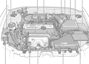
ENGINE COMPARTMENT
G010C01A-GAT (1.6 DOHC)
5 6
CAUTION:
When inspecting or ser- vicing the engine, you should handle tools and other heavy objects care- fully so that the plastic rocker cover of the engine is not damaged.
10
11
12
13
14
G010D01A-1
1. Engine coolant reservoir 2. Power steering fluid reservoir (If Installed) 3. Rocker cover 4. Engine oil filler cap 5. Brake booster
6. Brake fluid reservoir 7. Clutch fluid reservoir 8. Air filter element 9. Relay box 10. Windshield washer fluid reservoir cap
11. Engine oil level dipstick 12. Radiator cap 13. Automatic transaxle fluid level dipstick
(If Installed)
14. Battery
GENERAL CHECKS
G020A01A-AAT Engine Compartment
G020B01A-AAT Vehicle Exterior
G020C01A-AAT Vehicle Interior
DO-IT-YOURSELF MAINTENANCE
The following should be checked regularly:
The following should be checked monthly:
o Engine oil level and condition o Transaxle fluid level and condition o Brake fluid level o Clutch fluid level o Engine coolant level o Windshield washer fluid level o Accessory drive belt condition o Engine coolant hose condition o Fluid leaks (on or below components) o Power steering fluid level and condition o Battery Condition o Air filter condition
o Overall appearance and condition o Wheel condition and wheel nut tightness o Exhaust system condition o Light condition and operation o Windshield glass condition o Wiper blade condition o Paint condition and body corrosion o Fluid leaks o Door and hood lock condition o Tire pressure and condition
(including spare tire)
The following should be checked each time when the vehicle is driven:
o Light operation o Windshield wiper operation o Horn operation o Defroster, heater system operation (and air
conditioning, if installed)
o Steering operation and condition o Mirror condition and operation o Turn signal operation o Accelerator pedal operation o Brake operation, including parking brake o Manual transaxle operation, including clutch
operation
o Automatic transaxle operation, including
"Park" mechanism operation
o Seat control condition and operation o Seat belt condition and operation o Sun visor operation
If you notice anything that does not operate correctly or appear to be functioning correctly, inspect it carefully and seek assistance from your Hyundai dealer if service is needed.
6 DO-IT-YOURSELF MAINTENANCE
CHECKING THE ENGINE OIL
G030A01A-AAT Engine oil is essential to the performance and service of the engine. It is suggested that you check the oil level at least once a week in normal use and more often if you are on a trip or driving in severe conditions.
G030B01O-AAT Recommended Oil
o If SAE 5W-20, ILSAC GF-3 engine oil is not available, secondary recommended engine oil for corresponding temperature range can be used.
G030D01A-AAT Adding Oil
G030C02A-AAT To Check the Oil Level
G030D03A If the oil level is close to or below the "L" mark, add oil until it reaches the "F" mark. To add oil:
G030B01JM-U The engine oil quality should meet the following classification.
API SJ, SL or ABOVE, ILSAC GF-3 or ABOVE NOTE: o For good fuel economy, SAE 5W-20 (5W- 30), ILSAC GF-3 engine oil is preferred regardless of regional option and engine variation.
G030C03A Before checking the oil, warm up the engine to the normal operating temperature and be sure it is parked on level ground. Turn the engine off.
Wait five minutes, then remove the dipstick, wipe it off, fully reinsert the dipstick and with- draw it again. Then note the highest level the oil has reached on the dipstick. It should be be- tween the upper ("F") and lower ("L") range.
1. Remove the oil filler cap by turning it counter-
2. Add oil, then check the level again. Do not
clockwise.
overfill.
3. Replace the cap by turning it clockwise.
The distance between the "F" and "L" marks is equal to about 1 quart of oil.
CHANGING THE OIL AND FILTER
G040A03A-AAT
Oil filler cap
3. Slide underneath the car and loosen the drain plug by turning it counterclockwise with a wrench of the proper size. Be sure that a drain pan is in position to catch the oil as it drains out, then remove the drain plug.
WARNING:
Be very careful when draining the engine oil as it may be hot enough to burn you!
Oil filter .........
Drain plug
F040A02TB
4. When the oil has stopped draining, replace the drain plug using a new gasket and re- tighten by turning it clockwise.
The engine oil and filter should be changed at those intervals specified in the maintenance schedule in Section 5. If the car is being driven in severe conditions, more frequent oil and filter changes are required.
The procedure for changing the oil and filter is as follows: 1. Park the car on level ground and set the parking brake. Start the engine and let it warm up until the needle on the temperature gauge moves above the lowest mark. Turn the engine off and place the gear selector lever in "P" (automatic) or reverse gear (manual transaxle).
2. Open the hood and remove the engine oil
filler cap.
Oil pan drain plug tightening torque: 3.5 ~ 4.5 kgf.m
6.
5. Remove the oil filter by turning it counter- clockwise with a oil filter wrench of the proper size. A certain amount of oil will come out when you remove the filter. So be sure to have your drain pan in place underneath it. Install a new oil filter in accordance with the instructions on the carton or on the filter itself. Do not over-tighten (Tightening torque : 1.2 ~ 1.6 kgf.m). Be sure that the mounting surface on the engine is clean and that the old gasket is removed completely. Lubricate the new gas- ket on the filter before installation with clean engine oil.
DO-IT-YOURSELF MAINTENANCE
7. Refill the crankcase with the recommended engine oil. Refer to the specification in chap- ter 9 for engine oil capacity.
8. Start the engine and check to be sure no oil
is leaking from the drain plug or oil filter.
9. Shut off the engine and recheck the oil
level.
NOTE: Always dispose of used engine oil in an environmentally acceptable manner. It is sug- gested that it be placed in a sealed container and taken to a service station for reclama- tion. Do not pour the oil on the ground or put it in with the household trash.
PROPOSITION 65 WARNING: Used engine oil may cause irritation or can- cer of the skin if left in contact with the skin for prolonged periods of time. Used engine oil contains chemicals that have caused can- cer in laboratory animals. Always protect your skin by washing your hands thoroughly with soap and warm water as soon as pos- sible after handling used oil.
6 DO-IT-YOURSELF MAINTENANCE
CHECKING AND CHANGING THE ENGINE COOLANT
G050A01A-AAT
WARNING:
Do not remove the radiator cap when the engine is hot. When the engine is hot, the engine coolant is under pressure and may erupt through the opening if the cap is re- moved. You could be seriously burned if you do not observe this precaution. Do not re- move the radiator cap until the radiator is cool to the touch.
G050B01A-AAT Recommended Engine Coolant
G050C01A-AAT To Check the Coolant Level
Use a high quality ethylene-glycol coolant in a 50/50 mix with water. The engine coolant should be compatible with aluminum engine parts. Ad- ditional corrosion inhibitors or additives should not be used. The cooling system must be main- tained with the correct concentration and type of engine coolant to prevent freezing and corro- sion. Never allow the concentration of antifreeze to exceed the 60% level or go below the 35% level or damage to the coolant system may result. For proper concentration when adding or replacing the coolant, refer to the following table.
Ambient
temperature
°F (°C)
5 (-15)
-13 (-25)
-31 (-35)
-49 (-45)
Engine coolant
concentration
Antifreeze
solution
35%
40%
50%
60%
Water
65%
60%
50%
40%
HLC5005
The coolant level can be seen on the side of the plastic coolant reservoir. The level of the coolant should be between the "L" and "F" lines on the reservoir when the engine is cool. If the level is below the "L" mark, add engine coolant to bring it up between "L" and "F". If the level is low, inspect for coolant leaks and recheck the fluid level frequently. If the level drops again, visit your Hyundai dealer for an inspection and diag- nosis of the reason.G050D02A-AAT To Change the Coolant
The coolant should be changed at those inter- vals specified in the vehicle maintenance sched- ule in Section 5.
DO-IT-YOURSELF MAINTENANCE
CAUTION:
Engine coolant can damage the finish of your car. If you spill engine coolant on the car, wash it off thoroughly with clean water.
1. Park the car on level ground, set the parking brake and remove the radiator cap when cool.
2. Be sure your drain receptacle is in place. Open the drain cock on the radiator. Allow all the engine coolant to drain from the cooling system, then securely close the drain cock. 3. Check Section 9 for the capacity of the cooling system in your car. Then, following the manufacturer's directions on the engine coolant container, add the appropriate quan- tity of coolant to the radiator.
G050D01A
G050D02A
4. Turn the radiator cap counterclockwise with- out pressing down on it, until it stops. This relieves any pressure remaining in the cool- ing system. And remove the radiator cap by pushing down and turning counterclockwise. Now fill the radiator with clean demineralized or distilled water. Continue to add clean demineralized or distilled water in small quan- tities until the fluid level stays up in the radiator neck.
5. Start the engine, top off the radiator with water and then add engine coolant to the reservoir until the level is between "L" and "F".
6. Replace the radiator and reservoir caps and check to be sure the drain cocks are fully closed and not leaking.
6 DO-IT-YOURSELF MAINTENANCE
REPLACING THE SPARK PLUGS
G060B01A-AAT
WARNING:
The cooling fan is controlled by engine cool- ant temperature and may sometimes operate even when the engine is not running. Use extreme caution when working near the blades of the cooling fan so that you are not injured by a rotating fan blade. As the engine coolant temperature decreases, the fan will automatically shut off. This is a normal con- dition.
0.039 ~ 0.043 in. (1.0 ~ 1.1 mm )
G060A01L The spark plugs should be changed at the intervals specified in the vehicle maintenance schedule in section 5, or whenever engine per- formance indicates they should be changed. Symptoms that suggest poor spark plug perfor- mance include engine misfiring under load, loss of fuel economy, poor acceleration, etc. When spark plugs are replaced, always use spark plugs recommended by Hyundai. The use of other spark plugs can result in loss of perfor- mance, radio interference or engine damage.
NOTE: When replacing the spark plugs, genuine Hyundai replacement parts are recom- mended.
Recommended Spark Plugs: CHAMPION : RC10YC4
NGK : BKR5ES-11G060C01S-GAT Changing the Spark Plugs
You will find it easier to change spark plugs if the engine is cold. Always change one spark plug at a time. This helps avoid getting the wires mixed up.
G060C01A-D 1. Remove the center cover on the engine
rocker cover.
2. Using a clean cloth, remove any dirt that has accumulated around the base of the spark plug so it cannot fall into the cylinder when the spark plug is removed.
3. To remove the spark plug cable, pull straight up on the insulated connector, not the cable. Pulling on the cable may damage the carbon core conductor.
5. To remove the old spark plug, turn the wrench
handle in a counterclockwise direction.
DO-IT-YOURSELF MAINTENANCE
WARNING:
It is recommended that the engine be cool or cold when changing the spark plugs. If the engine is hot, you could burn yourself on the insulated connector, the spark plug or the engine itself.
4. When preparing to remove the old spark plug, guide the socket down over the spark plug, being careful not to damage the ce- ramic insulator.
6. To install the new spark plug, guide the socket down over the spark plug, being care- ful not to damage the ceramic insulator.
G060C03A-D
G060C04A-D
NOTE: Spark plugs should be tightened firmly. Over- tightening can damage the threads in the aluminum cylinder head. Also, leaving them too loose can cause the spark plugs to get very hot and possibly result in damage to the engine.
7. Replace the cable by pushing the insulated connector directly down onto the electrode. Check to be sure it has snapped into place and can't fall off.
G060C02A-D
6 DO-IT-YOURSELF MAINTENANCE 10
CHANGING THE AIR CLEANER FILTER G070A03Y-AAT
CAUTION:
o Operating your vehicle without a proper air filter in place can result in excessive engine wear.
o When removing the air cleaner filter, be careful that dust or dirt does not enter the air intake. These may result in damage to the air cleaner filter.
G070A01A
The replacement of air cleaner filter is per- formed in the following manner.
1. Unsnap the clips around the cover. 2. When this is done, the cover can be lifted off, the old filter removed and the new filter put in its place.
Genuine Hyundai replacement parts are recom- mended.
WINDSHIELD WIPER BLADES
G080A02A-AAT
HEF119
The wiper blades should be carefully inspected from time to time and cleaned to remove accu- mulations of road film or other debris. To clean the wiper blades and arms, use a clean sponge or cloth with a mild soap or detergent and water. If the wipers continue to streak or smear the glass, replace them with genuine Hyundai re- placement parts or their equivalent.
CAUTION:
o Do not operate the wipers on dry glass. This can result in more rapid wear of the wiper blades and may scratch the glass. o Keep the blade rubber out of contact with petroleum products such as engine oil, gasoline, etc.
FILLING THE WASHER RESERVOIR
CHECKING THE TRANSAXLE OIL (MANUAL)
G090A01A-AAT
G100A03A-AAT
DO-IT-YOURSELF MAINTENANCE
11
WARNING:
It is always better to check the transaxle oil level when the engine is cool or cold. If the engine is hot, you should exercise great caution to avoid burning yourself on hot engine or exhaust parts.
HLC5007
A good quality washer fluid should be used to fill the washer reservoir. The fluid level should be checked more frequently during inclement weath- er or whenever the washer system is in more frequent use. The capacity of the washer reservoir is 3.2 U.S. quarts (3.0 Liters).CAUTION:
o Radiator anti-freeze (engine coolant) should not be used in the washer system because it will damage the car's finish.
o The washer should not be operated if the washer reservoir is empty. This can dam- age the washer fluid pump.
Filler plug
Drain plug
HXGS506
Transaxle lubricant in the manual transaxle should be checked at those intervals specified in the vehicle maintenance schedule in Section 5.Recommended Oil Use only HYUNDAI GENUINE PARTS MTF 75W/85 (API GL-4) or equivalent in the manual transaxle.
Manual Transaxle Oil Capacity The oil capacity of the manual transaxle is 2.27
U.S. quarts (2.15 liters).G100B02A-AAT To check the Manual Transaxle Fluid Level
Park the car on level ground with the engine off.
G100B01L
6 DO-IT-YOURSELF MAINTENANCE 12
1. Using a wrench of the correct size, loosen the oil filler plug by turning it counterclock- wise and remove it with your fingers.
2. Use your finger or suitable tool to feel inside the hole. The oil level should be at its bottom edge. If it is not, check for leaks before adding oil. To refill the transaxle or bring the oil level up, add oil slowly until it reaches the proper level. Do not overfill.
3. Replace the plug and washer, screw it in with your fingers and then tighten securely with the wrench.
CHECKING THE TRANSAXLE FLUID (AUTOMATIC)
G110A01E-AAT Transaxle fluid in the automatic transaxle should be checked at those intervals specified in the vehicle maintenance schedule in Section 5.
NOTE: Automatic transaxle fluid is basically a red color. As driving distance increases, the fluid color turns darkish red gradually. It is a normal condition and you should not judge the need to replace based upon the chang- ing color. You must replace the automatic transaxle fluid in accordance with intervals specified in the vehicle maintenance schedule in sec- tion 5.
G110B05A-AAT Recommended Fluid Your Hyundai automatic transaxle is specially designed to operate with HYUNDAI GENUINE ATF SP III, DIAMOND ATF SP III, SK ATF SP III or other brands meeting the SP III specifi- cation approved by Hyundai Motor Co.. Damage caused by a nonspecified fluid is not covered by your new vehicle limited warranty.
CAUTION:
Use of aftermarket ATF additives may cause damage to the automatic transaxle. Only use HYUNDAI GENUINE ATF SP III, DIAMOND ATF SP III, SK ATF SP III or other brands meeting the SP III specification approved by Hyundai Motor Co.. If you are having your vehicle serviced at a facility other than a Hyundai dealer, verify that the correct ATF is used for your vehicle.
G110C02A-AAT Transaxle Fluid Capacity The fluid capacity of the automatic transaxle is 6.45 U.S. quarts (6.1 liters).
WARNING:
The transaxle fluid level should be checked when the engine is at normal operating tem- perature. This means that the engine, radia- tor, exhaust system etc., are very hot. Exer- cise great care not to burn yourself during this procedure.
G110D02A-AAT To Check the Transaxle Fluid Level
C090A01A
Park the car on level ground with the parking brake engaged. When the transaxle fluid level is checked, the transaxle fluid should be at normal operating temperature and the engine idling.
G110D03A
While the engine is idling, apply the brakes and move the gear selector lever from "P" to each of its other positions -- "R", "N", "D", "2", "L" -- and then return to "N" or "P". With the engine still idling:
1. Open the hood, being careful to keep hands, hair and clothing clear of any moving parts. 2. Remove the transaxle dipstick, wipe it clean, reinsert the dipstick as far as it will go, then remove it again. Now check the fluid level on the dipstick. It should be in the "HOT" range on the dipstick.
DO-IT-YOURSELF MAINTENANCE
13
Fluid level should be within "HOT" range
3.
G110D04A If the transaxle fluid level is low, use a funnel to add transaxle fluid through the dipstick tube until the level reaches the "HOT" range. Do not overfill.
WARNING:
The cooling fan is controlled by the engine coolant temperature and may sometimes op- erate even when the engine is not running. Use extreme caution when working near the blades of the cooling fan, so that you are not injured by a rotating fan blade. As the engine coolant temperature decreases, the fan will automatically shut off. This is a normal con- dition.
6 DO-IT-YOURSELF MAINTENANCE 14
CHECKING THE BRAKES
G120A01A-AAT
CAUTION:
Because brakes are essential to the safe operation of the car, it is suggested that they be checked and inspected by your Hyundai dealer. The brakes should be checked and inspected for wear at those intervals speci- fied in the vehicle maintenance schedule in Section 5.
G120B01A-AAT Checking the Brake Fluid Level
WARNING:
Use caution when handling brake fluid. It can damage your vision if it gets into your eyes. It will also damage your vehicle's paint if spilled on it and not removed immediately.
G120C02A-AAT Recommended Brake Fluid
G120E02A-AAT Adding Brake Fluid
WARNING:
Handle brake fluid carefully. It can damage your vision if it gets into your eyes. Use only DOT 3 or DOT 4 specification fluid from a sealed container. Do not allow the fluid can or reservoir to remain open any longer than required. This will avoid entry of dirt and moisture which can damage the brake sys- tem and cause improper operation.
To add brake fluid, first wipe away any dirt then unscrew the fluid reservoir cap. Slowly pour the recommended fluid into the reservoir. Do not overfill. Carefully replace the cap on the reser- voir and tighten.
Use only hydraulic brake fluid conforming to DOT 3 or DOT 4 specifications in your braking system. Follow the instructions printed on the container.
G120D01A-AAT To Check the Fluid Level
HLC5035
The fluid level in the brake fluid reservoir should be checked periodically. The level should be between the "MIN" and "MAX" marks on the side of the reservoir. If the level is at or below the "MIN" mark, carefully add fluid to bring it up to "MAX". Do not overfill.
CHECKING THE CLUTCH FLUID
G130A01A-AAT To Check the Clutch Fluid
G130B02A-AAT To Replace the Fluid
Recommended brake fluid conforming to DOT 3
or DOT 4 specification should be used. The reservoir cap must be fully tightened to avoid contamination from foreign matter or moisture.NOTE: Do not allow any other liquids to contami- nate the brake fluid. Seal damage will result.
DO-IT-YOURSELF MAINTENANCE
AIR CONDITIONER CARE
15
G140A01A-AAT Keeping the Condenser Clean
The air conditioner condenser (and engine ra- diator) should be checked periodically for accu- mulation of dirt, dead insects, leaves, etc. These can interfere with maximum cooling efficiency. When removing such accumulations, brush or hose them away carefully to avoid bending the cooling fans.
WARNING:
Use caution when handling brake fluid. It can damage your vision if you get it in your eyes. It will also damage your vehicles paint if spilled on it and not removed immediately.
HLC5036
The clutch fluid level in the master cylinder should be checked when performing other un- der hood services. The system should be checked for leakage at the same time. Check to make certain that the clutch fluid level is between the "MAX" and "MIN" level markings on the fluid reservoir. Fill as required. Fluid loss indicates a leak in the clutch system which should be inspected and repaired immediately. Consult your Hyundai dealer.6 DO-IT-YOURSELF MAINTENANCE 16
G140B01A-AAT Checking the Air Conditioner Opera- tion
1. Start the engine and let it run at fast idle for several minutes with the air conditioner set at the maximum cold setting. If the air coming out of the in-dash vents is not cold, have the air conditioning system inspected by your Hyundai dealer.
2.
CAUTION:
Running the air conditioning system for ex- tended periods of time with a low refrigerant level may damage the compressor.
G140C01A-AAT Lubrication
To lubricate the compressor and the seals in the system, the air conditioner should be run for at least 10 minutes each week. This is particularly important during cool weather when the air con- ditioning system is not otherwise in use.
G140D02A-AAT Checking the Compressor Drive Belt
A/C
0.315 in. (8mm)
TENSION PULLEY
CRANK PULLEY
G140D01A
When the air conditioning is being used regular- ly, the compressor drive belt tension should be checked at least once a month with the engine turned off. To check the drive belt tension, press down on the belt halfway between the engine crankshaft and compressor pulleys. Pressing with your finger, you should not be able to deflect this belt anymore than 1/3 of an inch. If the belt is too loose, have it adjusted by your Hyundai dealer.
CHANGING THE AIR CONDITIONER FILTER B145A02A-GAT (For Evaporator and Blower Unit) (If Installed)
The air conditioner filter is located in front of the evaporator unit behind the glove box. It helps to decrease the amount of pollutants entering the car.
(2)
(1)
HLC2096
1. Open the glove box and by pushing at the outside of adjusting pin (1) first and then sliding the adjusting pin (2) in makes it easier to remove adjusting pin.
DO-IT-YOURSELF MAINTENANCE
CHECKING THE FREE-PLAY
17
3. Remove the filter cover by pushing the upper
end of the filter cover.
G150A01A-AAT Steering Wheel
2. Remove the cable and the wiring from the
filter cover.
HLC2097
4. Replace the two filters. 5.
Installation is the reverse order of disassem- bly.
HLC2099
CAUTION:
Be sure to install the air conditioner filter in the direction of the arrow sign. Otherwise, it may cause noise or deterioration.
HLC2098
1.18 in. (30 mm)
HLC5008
To check the steering wheel free-play, stop the car with the wheels pointed straight ahead and gently move the steering wheel back and forth. Use very light finger pressure and be sensitive to changes in resistance that mark the limits of the free-play. If the free-play is greater than specified, have it inspected by your Hyundai dealer and adjusted or repaired if necessary.
6 DO-IT-YOURSELF MAINTENANCE 18
G160A01A-AAT Clutch Pedal
G170A01A-AAT Brake Pedal
CHECKING BRAKE PEDAL CLEARANCE
G180A01A-AAT
0.24 ~ 0.51 in. (6 ~ 13 mm)
0.12 ~ 0.31 in. (3 ~ 8 mm)
1.78 in. (45.1 mm)
G180A01L
G160A01E With the engine off, press lightly on the clutch pedal until you feel a change in resistance. This is the clutch pedal free-play. The free-play should be within the limits specified in the illustration below. If it is not, have it inspected by your Hyundai dealer and adjusted or repaired if nec- essary.
HXGS508
With the engine off, press down on the brake pedal several times to reduce the vacuum in the brake booster. Then, using your hand, press down slowly on the brake pedal until you feel a change in resis- tance. This is the brake pedal free-play. The free-play should be within the limits speci- fied in the illustration above. If it is not, have it inspected by your Hyundai dealer and adjusted or repaired if necessary.
You need a helper to check the brake pedal clearance. With the engine running, have your helper press down on the brake pedal several times and then hold it down with a force of about 110 lbs (50 kg, 490 N). The brake pedal clear- ance is the distance from the top surface of the brake pedal to the asphalt sheeting under the floor mat. If the brake pedal clearance is not within the limits specified in the illustration, have it in- spected by your Hyundai dealer and adjusted or repaired if necessary.
DO-IT-YOURSELF MAINTENANCE
19
CAUTION:
When replacing a fusible link, never use anything but a new fusible link with the same or lower amperage rating. Never use a piece of wire or a higher-rated fusible link. This could result in serious damage and create a fire hazard.
CHECKING DRIVE BELTS
G190A01A-AAT
Water Pump Pulley
CHECKING AND REPLACING FUSES G200A01A-AAT Replacing a Fusible Link
0.2~0.24 in. (5.1~6 mm)
Alternator Pulley
Open- Replace
Good
Crankshaft Pulley
HTB186
Drive belts should be checked periodically for proper tension and adjusted if necessary. At the same time, belts should be examined for cracks, wear, fraying or other evidence of deterioration and replaced if necessary. Belt routing should also be checked to be sure there is no interference between the belts and other parts of the engine. After a belt is replaced, the new belt should be adjusted again after two or three weeks to eliminate slack resulting from initial stretching after use.
G200A01A A fusible link will melt if the electrical circuits from the battery are ever overloaded, thus pre- venting damage to the entire wiring harness. (This could be caused by a short in the system drawing too much current.) If this ever happens, have a Hyundai dealer determine the cause, repair the system and replace the fusible link. The fusible links are located in a relay box for easy inspection.
6 DO-IT-YOURSELF MAINTENANCE 20
G200B01A-AAT Replacing Accessory Fuses
1. Turn off the ignition and all other switches. 2. Open the fuse box and examine each fuse. Remove each fuse by pulling it toward you (a small "fuse puller" tool is contained in the fuse box to simplify this operation).
3. Be sure to check all other fuses even if you
find one that appears to have opened.
HLC4002
The fuse box for the lights and other electrical accessories will be found low on the dashboard on the driver's side. Inside the box you will find a list showing the circuits protected by each fuse. If any of your car's lights or other electrical accessories stop working, a blown (open) fuse could be the reason. If the fuse has opened, you will see that the metal strip inside the fuse has melted through. If you suspect a blown fuse, follow this procedure:
HLC4003
4. Replace the blown fuse by pressing a new fuse of the same rating into place. The fuse should be a snug fit. If it is not, have the fuse clip repaired or replaced by a Hyundai deal- er. If you do not have a spare fuse, you may be able to borrow a fuse of the same or lower rating from an accessory you can tempo- rarily get along without (the radio or cigarette lighter, for example). Always remember to replace the borrowed fuse.
Good
Open - Replace
G200B02L
CAUTION:
An open fuse indicates that there is a prob- lem in the electrical circuit. If you replace a fuse and it blows as soon as the accessory is turned on, the problem is serious and should be referred to a Hyundai dealer for diagnosis and repair. Never replace a fuse with anything except a fuse with the same or a lower amperage rating. A higher capacity fuse could cause damage and create a fire hazard.
NOTE: See page 6-32 for the fuse panel descrip- tions.
CHECKING THE BATTERY
G210A01A-AAT
D010B01A
WARNING:
When working with batteries, carefully ob- serve the following precautions to avoid se- rious injuries.
The fluid in the battery contains a strong solution of sulfuric acid, which is poisonous and highly corrosive. Be careful not to spill it on yourself or the car. If you do spill battery fluid on yourself, immediately do the following:
o If battery fluid is on your skin, flush the affected areas with water for at least 15
minutes and then seek medical assistance. o If battery fluid is in your eyes, rinse out your eyes with water and get medical assistance as soon as possible. While you are being driven to get medical assistance, continue to rinse your eyes by using a sponge or soft cloth saturated with water.o If you swallow battery fluid, drink a large quantity of water or milk followed by milk of magnesia, eat a raw egg or drink vegetable oil. Get medical assistance as soon as pos- sible.
While batteries are being charged (either by a battery charger or by the vehicle's alternator), they produce explosive gases. Always observe these warnings to prevent injuries from occur- ring: o Charge batteries only in a well ventilated
o Do not permit flames, sparks or smoking in
area.
the area.
o Keep children away from the area.
DO-IT-YOURSELF MAINTENANCE
21
G210B02A-AAT Checking the Battery
Keep the battery clean. Any evidence of corro- sion around the battery posts or terminals should be removed using a solution of household bak- ing soda and warm water. After the battery terminals are dry, cover them with a light coating of grease.
WARNING:
Always read the following instruc- tions carefully when handling a battery. Keep lighted cigarettes and all other flames or sparks away from the battery. Hydrogen, which is a highly com- bustible gas, is always present in battery cells and may explode if ignited. Keep batteries out of the reach of children because batteries con- tain highly corrosive SULFURIC ACID. Do not allow battery acid to contact your skin, eyes, clothing or paint finish.
6 DO-IT-YOURSELF MAINTENANCE 22
CHECKING ELECTRIC COOLING FANS G220A01A-AAT
POWER STEERING FLUID LEVEL
G230A03A-AAT
If any electrolyte gets into your eyes, flush your eyes with clean water for at least 15 minutes and get immediate medical attention. If possible, continue to apply wa- ter with a sponge or cloth until medical attention is received. If electrolyte gets on your skin, thoroughly wash the contacted area. If you feel a pain or a burning sensation, get medical attention immediately. Wear eye protection when charg- ing or working near a battery. Always provide ventilation when working in an enclosed space.
o When lifting a plastic-cased battery, ex- cessive pressure on the case may cause battery acid to leak, resulting in personal injury. Lift with a battery carrier or with your hands on opposite corners.
o Never attempt to charge the battery when
the battery cables are connected.
o The electrical ignition system works with
high voltage. Never touch these components with the engine running or the ignition switched on.
WARNING:
The radiator fan is controlled by engine cool- ant temperature and may sometimes operate even when the engine is not running. Use extreme caution when working near the blades of the cooling fan, so that you are not injured by a rotating fan blade. As the cool- ant temperature decreases the fan will auto- matically shut off. This is a normal condition.
G220B01A-AAT Checking Engine Cooling Fan
The engine cooling fan should come on auto- matically if the engine coolant temperature is high.
G220C01A-AAT Checking Condenser Cooling Fan
The condenser cooling fan should come on automatically whenever the air conditioner is in operation.
HLC5006
The power steering fluid level should be checked regularly. To check the power steering fluid level, be sure the engine is "OFF", then check to make certain that the power steering fluid level is between the "MAX" and "MIN" level markings on the fluid reservoir.NOTE: Grinding noise from the power steering pump may be heard immediately after the engine is started in extremely cold conditions (below -4°F). If the noise stops during warm up, there is no abnormal function in the system. It is due to a power steering fluid character- istic in extremely cold conditions.
Recommended Fluid Use PSF-3 type fluid
NOTE: Do not start the engine when the power steering oil reservoir is empty.
G240A01A-AAT POWER STEERING HOSES
It is suggested that you check the power steer- ing hose connections for fluid leakage at those intervals specified in the vehicle maintenance schedule in Section 5. The power steering hoses should be replaced if there is severe surface cracking, pulling, scuff- ing or worn spots. Deterioration of the hose could cause premature failure.
DO-IT-YOURSELF MAINTENANCE
HEADLIGHT AIMING ADJUSTMENT
23
G250A01A-AAT FOR MORE INFORMATION ABOUT YOUR HYUNDAI
G290A04A-AAT Before performing aiming adjustment, make sure of the following.
If you desire additional information about main- taining and servicing your Hyundai, you may purchase a factory Shop Manual at your Hyundai dealer's parts department. This is the same manual used by dealership technicians and while it is highly technical it can be useful in obtaining a better understanding of your car and how it works.
1. Keep all tires inflated to the correct pressure. 2. Place the vehicle on level ground and press the front bumper & rear bumper down sever- al times. Place vehicle at a distance of 118
in. (3m) from the test wall.3. See that the vehicle is unloaded (except for full levels of coolant, engine oil and fuel, and spare tire, jack, and tools). Have the driver or equivalent weight placed in driver's seat.
4. Clean the headlight lenses and turn on the
headlights (Low beam).
5. Open the hood.
Vertical Aiming
G290A01A-1
6 DO-IT-YOURSELF MAINTENANCE 24
6. Draw the vertical line (through the center of each headlight) and the horizontal line (through the center of each headlight) on the aiming screen. And then, draw a parallel line at 0.8 in.(21
mm) under the horizontal line.7. Adjust each cut-off line of the low beam to
the parallel line with a phillips screwdriver - VERTICAL AIMING
WARNING:
Horizontal aiming should be adjusted by an authorized Hyundai dealer.
SPECIFICATIONS:
"H"; Horizontal center line of headlights from ground : 25.8 in. (656 mm)
"W"; Distance between each headlight center : 42.4 in. (1,078 mm)
"L"; Distance between the headlights and the wall that the lights are tested against: 118 in. (3,000 mm).
G290B02A-AAT Adjustment After Headlight Assembly Replacement
0.8 in. (21mm)
Vertical line
Horizontal line
"P"
Ground line
G290B01A-2
Cut-off line
If the vehicle has had front body repair and the headlight assembly has been replaced, the head- light aiming should be checked using an aiming screen as shown in the illustration. Turn on the headlight switch. (Low Beam Position)
1. Adjust headlights so that main axis of light is parallel to center line of the body and is aligned with point "P" shown in the illustra- tion.
2. Dotted lines in the illustration show the cen-
ter of headlights.
REPLACEMENT OF LIGHT BULBS
G260A02A-AAT Before attempting to replace a light bulb, be sure the switch is turned to the "OFF" position. The next paragraph shows how to reach the light bulbs so they may be changed. Be sure to replace the burned-out bulb with one of the same number and wattage rating. See page 6-31 for the wattage descriptions
G270A03A-AAT Headlight Bulb
1. Allow the bulb to cool. Wear eye protection. 2. Open the engine hood. 3. Always grasp the bulb by its plastic base,
avoid touching the glass.
DO-IT-YOURSELF MAINTENANCE
25
CAUTION:
Keep the lamps out of contact with petro- leum products, such as oil, gasoline, etc.
4. Using a socket wrench of the correct size, remove the headlight assembly mounting bolts.
HLC5033
HLC5034-1
5. Disconnect the power cord from the bulbbase in the back of the headlight.
6. Remove the dust cover.
HLC5009
6 DO-IT-YOURSELF MAINTENANCE 26
7. Push the bulb spring to remove the headlight
bulb.
HLC5010
HLC5011
G270A03O
8. Remove the protective cap from the replace- ment bulb and install the new bulb by match- ing the plastic base with the headlight hole. Re-attach the bulb spring and install the dust cover. Reconnect the power cord.
9. Use the protective cap and carton to dispose
of the old bulb.
10.Check for proper headlight aim.
WARNING:
The halogen bulb contains gas under pres- sure and if impacted could shatter, resulting in flying fragments. Always wear eye protec- tion when servicing the bulb. Protect the bulb against abrasions or scratches and against liquids when lighted. Turn the bulb on only when installed in a headlight. Re- place the headlight if damaged or cracked. Keep the bulb out of the reach of children and dispose of the used bulb with care.
G270B01A-GAT Front Turn Signal light / Position Light
(2)
(1)
G270D01TB-AAT Rear Combination Light 4 Door
DO-IT-YOURSELF MAINTENANCE
27
HLC5034
1. Disconnect the power cord from the bulb.HLC5012
2. To replace the front turn signal light (1) or position light (2), take it out from the bulb holder by turning it counterclockwise. Install the new bulb.
3.
3 Door
G270D01A
1. Open the trunk lid/tail gate.
HLC5015
6 DO-IT-YOURSELF MAINTENANCE 28
2. Remove the mounting screws as shown with
a phillips screwdriver.
4 Door
3. To replace the rear combination light (stop/ tail light, turn signal light or back-up light), take it out from the bulb holder by turning it counterclockwise.
G270C01TB-AAT Luggage Compartment Light (If Installed) 3 Door
4 Door
(1) Stop/Tail Light (2) Turn Signal Light (3) Back-up Light
4.
Install the new bulb.
3 Door
(2)
(3)
(1)
(3)
(1)
(2)
G270D02A
HLC5016
1. Remove the cover with a flat-head screw-
driver.
HLC5014
G270G01A-AAT Interior Light (Map Light) (If Installed)
DO-IT-YOURSELF MAINTENANCE
29
2. Disconnect the power cord.
HTB283
HLC5017
2. Replace with a new bulb.
HLC5018
1. Remove the cover with a flat-head screw-
driver.
3. Replace with a new bulb.
HTB284
6 DO-IT-YOURSELF MAINTENANCE 30
G270H01A-AAT Interior Light
HLC5019
2. Replace with a new bulb.
HLC5020
1. Remove the cover with a flat-head screw-
driver.
BULB WATTAGES
G280A03A-AAT
4 DOOR
3 DOOR
DO-IT-YOURSELF MAINTENANCE
31
12
10
11
11
10
12
G280A02A
No.
Part Name
Front Position Light Headlight (High/Low) Front Turn Signal Light Interior Light (Map Light) (If Installed) Interior Light Front Fog Light (If Installed) Front Side Marker Light
Wattage
60/55
27
10
10
27No.
10
11
12Part Name
Rear Combination Light
Turn Signal Light Stop/Tail Light Back-up Light
High Mounted Rear Stop Light (If Installed) Rear Side Marker Light Luggage Compartment Light (If Installed) License Plate Light
Wattage
27
27/8(4 Door), 28/8(3 Door)
17
176 DO-IT-YOURSELF MAINTENANCE 32
FUSE PANEL DESCRIPTION
G200C02A-GAT Engine Compartment
DESCRIPTION ALT
FUSIBLE
LINK
BATTERY
LAMP ECU IGN
RAD FAN BLOWER
ABS ABS
P/WDW
COND FAN
FUSE RATING
PROTECTED COMPONENTS
120A 50A 50A 20A 30A 20A 30A 30A 30A 30A 20A
Charging (Generator) Fuse 6, 7, 8, 9, Horn fuse, Room lamp fuse Head lamp fuse, Front fog lamp fuse, Tail lamp relay, H/LP washer fuse Engine control relay, Generator, Fuel pump relay, ECU #3 fuse Ignition power source, Start relay Radiator fan control Blower control ABS control, ABS bleeding connector ABS control, ABS bleeding connector Power window Condenser fan control
NOTE: Not all fuse panel descriptions in this manual may be applicable to your vehicle. It is accurate at the time of printing. When you inspect the fuse box on your vehicle, refer to the fuse box label.
HLC5027
DESCRIPTION
FUSE RATING
PROTECTED COMPONENTS
DO-IT-YOURSELF MAINTENANCE
33
ECU #1
A/CON COMP
HORN
TAIL LH
TAIL RH H/LP LH H/LP RH
FRONT FOG
ROOM LP
AUDIO
ECU #2
ECU#3
FUSE
H/L WASHER F/PUMP CHK (E50)
10A
10A 10A
10A
10A 10A 10A 15A
10A
15A
15A
10A 25A
Radiator fan, Condenser fan, ECM, Oxygen sensor, Purge control valve, SMATRA, Glow plug relay, Heater relay, Stop lamp switch A/C relay Horn relay Illumination lamps, Left rear combination lamp, License lamp, DRL control, Position lamp, H/LP washer relay Right rear combination lamp, License lamp, Position lamp Left head lamp, DRL control, Instrument cluster Right head lamp Front fog lamp relay Instrument cluster, Courtesy lamp, Trunk room lamp, ETACM, DLC, Door warning, Multipurpose check connector Audio, Digital clock, Power antenna, A/C switch, Rear fog lamp switch Idle speed actuator, ECM, Camshaft position sensor, EGR actuator, Throttle plate actuator ECM Head lamp washer motor Fuel pump relay, Fuel pump motor
6 DO-IT-YOURSELF MAINTENANCE 34
G200E01A-GAT Inner Panel
FUSE
FUSE RATING
PROTECTED COMPONENTS
10
11
12
13
14
15
16
17
1810A
10A 10A 15A
10A
10A 10A 10A 20A
10A
20A 20A 10A 10A 15A 10A 10A 20A
Hazard warning, Back-up lamp switch, Transaxle range switch, A/T shift & key lock control module ETACM, Pre-Excitation resistor, Instrument cluster, Seat belt timer Instrument cluster Air bag ECM, A/T shift lever, Transaxle range switch, Mass air flow sensor, Vehicle speed sensor, Water sensor Power door lock Hazard warning, ETACM Stop lamp, A/T shift lever, A/T key interlock solenoid Rear window defogger Head lamp, Power window, Head lamp leveling, Head lamp washer, ETACM, Front fog lamp, Blower control, Rear intermittent washer, Fuel filter relay Front wiper & washer Seat warmer ABS control, ABS bleeding Digital clock, Audio, A/T shift & key lock control module Cigarette lighter Power outside mirror Rear window & outside mirror defogger Rear wiper
HLC5031
EMISSION CONTROL SYSTEMS
Emission Control System ............................................. 7-2
Catalytic Converter ....................................................... 7-37 EMISSION CONTROL SYSTEMS
EMISSION CONTROL SYSTEM
H010A01A-AAT Your Hyundai is equipped with an emission control system to meet all requirements of the U.S. Environmental Protection Agency or Cali- fornia Air Resources Board. There are three emission control systems which are as follows.
1) Crankcase Emission Control System 2) Evaporative Emission Control System 3) Exhaust Emission Control System
In order to ensure the proper function of the emission control systems, it is recommended that you have your car inspected and main- tained by an authorized Hyundai dealer in accordance with the maintenance schedule in this manual.
H010B01A-AAT 1. CRANKCASE EMISSION CONTROL
SYSTEM
The positive crankcase ventilation system is employed to prevent air pollution caused by blow-by gases being emitted from the crank- case. This system supplies filtered fresh air to the crankcase through the air intake hose. Inside the crankcase, the fresh air mixes with blow-by gases, then passes through the PCV valve into the induction system.
H010C01S-AAT 2. Evaporative Emission Control (Includ- ing ORVR: Onboard Refueling Vapor Recovery) System
The Evaporative Emission Control System is designed to prevent fuel vapors from escaping into the atmosphere. (The ORVR system is designed to allow the vapors from the fuel tank to be loaded into a canister while refueling at the gas station, preventing the escape of fuel vapors into the atmosphere.)
Canister
Fuel vapors generated inside the fuel tank are absorbed and stored in the onboard canister. When the engine is running, the fuel vapors absorbed in the canister are drawn into the induction system through the purge control solenoid valve.
Purge Control Solenoid Valve (PCSV)
The purge control solenoid valve is controlled by the Engine Control Module (ECM); when the engine coolant temperature is low during idling, the PCSV closes so that evaporated fuel is not taken into the engine. After the engine warms-up during ordinary driving, the PCSV opens to introduce evaporated fuel to the engine.
H010D01A-AAT 3. EXHAUST EMISSION
CONTROL SYSTEM
The Exhaust Emission Control System is a highly effective system which controls ex- haust emissions while maintaining good ve- hicle performace.
EMISSION CONTROL SYSTEMS
system.
WARNING:
o Remember that your Hyundai dealer is
your best source of assistance.
o Do not stop your Hyundai over any combustible material such as grass, paper, leaves or rags. These materials might contact the hot catalytic con- verter and a fire might result.
CATALYTIC CONVERTER
H020A01A-AAT
Catalytic Converter
HLC5022
All Hyundai vehicles are equipped with a mono- lith type three-way catalytic converter to reduce the carbon monoxide, hydrocarbons and nitrogen oxides contained in the exhaust gas. Exhaust gases passing through the cata- lytic converter cause it to operate at a very high temperature. The introduction of large amounts of unburned gasoline into the ex- haust may cause the catalytic converter to overheat and create a fire hazard. This risk may be reduced by observing the following:
WARNING:
o Use unleaded fuel only. o Maintain the engine in good operating condition. Extremely high catalytic con- verter temperatures can result from im- proper operation of the electrical, igni- tion or multiport electronic fuel injec- tion.
o If your engine stalls, pings, knocks, or is hard to start, have your Hyundai dealer inspect and repair the problem as soon as possible.
o Avoid driving with a very low fuel level. Running out of gasoline may cause the engine to misfire and result in damage to the catalytic converter.
o Avoid idling the engine for periods
longer than 10 minutes.
o The vehicle should not be pushed or pulled to get started. This may cause the catalytic converter to overheat and create a fire hazard.
o Do not touch the catalytic converter or any other part of the exhaust system while the catalytic converter is hot. Shut off the engine, wait for at least one hour before touching the catalytic con- verter or any other part of the exhaust
CONSUMER INFORMATION, REPORTING
SAFETY DEFECTS & BINDING
ARBITRATION OF WARRANTY CLAIMS
Vehicle Identification Number (VIN) ............................. 8-2
Engine Number ............................................................. 8-2
Recommended Cold Tire Inflation Pressures .............. 8-3
Snow Tires.................................................................... 8-9
Tire Chains ................................................................. 8-10
Tire Rotation ............................................................... 8-10
Tire Balancing ............................................................. 8-11
Tire Traction................................................................ 8-11
When to Replace Tires ............................................... 8-11
Spare Tire and Tools .................................................. 8-12
Warranties for Your Hyundai Vehicle ......................... 8-12
Consumer Information ................................................ 8-13
Reporting Safety Defects ........................................... 8-15
Binding Arbitration of Warranty Claims ...................... 8-168 CONSUMER INFORMATION, REPORTING SAFETY DEFECTS & BINDING ARBITRATION OF WARRANTY CLAIMS
ENGINE NUMBER
VEHICLE IDENTIFICATION NUMBER (VIN)
I010A02A-AAT
I010B01A-AAT
I010A01A-1
The vehicle identification number (VIN) is the number used in registering your car and in all legal matters pertaining to its ownership, etc. It can be found in four different places on your car:The engine number is stamped on the engine block as shown in the drawing.
F040A02TB-1
TIRES
I020A02A-AAT TIRE INFORMATION The tires supplied on your new Hyndai are chosen to provide the best perfor- mance for normal driving. If you ever have questions about your tire warranty and where to obtain ser- vice, see the tire manufacture's book- let included with your vehicle's Owner's Manual Literature Kit.
1. On the bulkhead between the engine and
passenger compartments.
2. On the left top side of the instrument panel where it can be seen by looking down through the windshield. 3. Door edge post 4. On the lower side of the center pillar outer
panel.
I030A02JM-AAT
RECOMMENDED COLD TIRE INFLA- TION PRESSURES
I030A01A-2
Tire label located on the driver's side of the center pillar outer panel gives the cold tire pressures recommended for your vehicle with the original tire size, the number of people that can be in your vehicle and vehicle capacity weight.
CONSUMER INFORMATION, REPORTING SAFETY DEFECTS & BINDING ARBITRATION OF WARRANTY CLAIMS
WARNING:
Severe underinflation (10 psi (70
kPa) or more) can lead to severe heat buildup, causing blowouts, tread separation and other tire fail- ures that can result in the loss of vehicle control leading to severe injury or death. This risk is much higher on hot days and when driv- ing for protracted periods at high speeds.I030A01LC-1
I030A01LC-2
These pressures were chosen to pro- vide the most satisfactory combina- tion of ride comfort, tire wear and stability under normal conditions. Tire pressures should be checked at least monthly. Proper tire inflation pressures should be maintained for these rea- sons:
8 CONSUMER INFORMATION, REPORTING SAFETY DEFECTS & BINDING ARBITRATION OF WARRANTY CLAIMS
NOTE: o Underinflation also results in ex- cessive wear, poor handling and reduced fuel economy. Wheel de- formation also is possible. Keep your tire pressures at the proper levels. If a tire frequently needs refilling, have it checked by your Hyundai Dealer.
o Overinflation produces a harsh ride, excessive wear at the center of the tire tread, and a greater possibility of damage from road hazards.