- 2008 Hummer H2 Owners Manuals
- Hummer H2 Owners Manuals
- 2006 Hummer H2 Owners Manuals
- Hummer H2 Owners Manuals
- 2009 Hummer H2 Owners Manuals
- Hummer H2 Owners Manuals
- 2004 Hummer H2 Owners Manuals
- Hummer H2 Owners Manuals
- 2007 Hummer H2 Owners Manuals
- Hummer H2 Owners Manuals
- 2005 Hummer H2 Owners Manuals
- Hummer H2 Owners Manuals
- Download PDF Manual
-
If express override is activated, the midgate window will not reverse automatically. You or others could be injured and the window could be damaged. Before you use express override, make sure that all people and obstructions are clear of the midgate window path.
Midgate Window Express Override Mode If an obstruction or weather condition such as severe icing stops the window as it is moving upward, the window will automatically reverse to a partially open position. The window will return to normal operation once the obstruction or condition is removed.
2-22
The window auto-reversal function can be overridden in the express override mode. To override, the window must be operated manually by pressing and holding the Midgate window switch or the global window button. This must be done within two seconds after the Midgate window has stopped at a partially open position. The express override mode only works immediately following a window auto-reversal. Window express functions will not work while in this mode.
Midgate Window Error/Jog Mode If the Midgate window has sensed conditions which may lead to damage or malfunction of the window system, the window will automatically go into Error/Jog mode. In this mode, window express functions will not work. The window can only be operated manually by pressing the Midgate window switch or the global window button. The window will move slightly and stop. Press and hold the window switch or global window button to continue to close the window a small amount at a time.
To Exit Error/Jog Mode 1. Ensure normal Midgate window operating conditions
have begun.
2. Press and hold the Midgate window down switch
approximately one second to start window express-down.
3. Release the window down switch and allow the
window to fully open. Do not use any window switches once window movement has started.
4. Press the Midgate window up switch and visually confirm that the express-up has been completed.
Sun Visors Swing the sun visor down to block glare. Swing the sun visor to the side to cover the side window. Illuminated Visor Vanity Mirrors Swing the sun visor down and lift the mirror cover to turn the lamps on.
2-23
Theft-Deterrent Systems Vehicle theft is big business, especially in some cities. Although your vehicle has a number of theft-deterrent features, we know that nothing we put on it can make it impossible to steal.
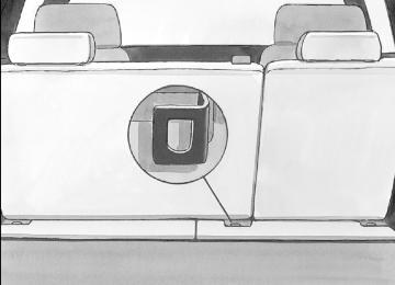
Content Theft-Deterrent Your vehicle is equipped with a content theft-deterrent alarm system.
With this system, the security light in the instrument panel cluster will flash as you open the door if your ignition is off.
This light reminds you to activate the theft-deterrent system.
To activate the theft-deterrent system: 1. Open the door. 2. Lock the door with the Remote Keyless Entry (RKE)
transmitter. The security light will illuminate to inform the driver the system is arming. If a door is open when the doors are locked, the security light will flash.
3. Close all doors. The security light should go off after about 30 seconds. The alarm is not armed until the security light goes off. If the delayed locking feature is turned on, the theft-deterrent system will not start the arming process until the last door is closed and the delay timer has expired. See Delayed Locking on page 2-11.
If a locked door is opened without the RKE transmitter, the alarm will go off. The headlamps and parking lamps will flash and the horn will sound for 30 seconds, then will turn off to save the battery power.
2-24
Remember, the theft-deterrent system will not activate if you lock the doors with the vehicle’s key or use the manual door lock. It activates only if you use a power door lock switch with the door open, or with the RKE transmitter. You should also remember that you can start your vehicle with the correct ignition key if the alarm has been set off. Here is how to avoid setting off the alarm by accident:
If you do not want to activate the theft-deterrent system, the vehicle should be locked with the door key after the doors are closed.
(cid:129) Always unlock a door with the RKE transmitter. Unlocking a door any other way will set off the alarm.
If you set off the alarm by accident, press unlock on the RKE transmitter or place the key in the ignition and turn it to START to turn it off. The alarm will not stop if you try to unlock a door any other way.
Testing the Alarm To test the alarm: 1. From inside the vehicle, lower the driver’s window
and open the driver’s door.
2. Activate the system by locking the doors with the power door lock switch while the door is open, or with the RKE transmitter.
3. Get out of the vehicle, close the door and wait for
the security light to go out.
4. Then reach in through the window, unlock the door with the manual door lock and open the door. This should set off the alarm.
While the alarm is set, the power door unlock switch is not operational. If the alarm does not sound when it should but the headlamps flash, check to see if the horn works. The horn fuse may be blown. To replace the fuse, see Instrument Panel Fuse Block on page 5-111 and Underhood Fuse Block on page 5-113. If the alarm does not sound or the headlamps do not flash, the vehicle should be serviced by your dealer/retailer.
2-25
(cid:129) PASS-Key® III+ The PASS-Key® III+ system operates on a radio frequency subject to Federal Communications Commission (FCC) Rules and with Industry Canada. This device complies with Part 15 of the FCC Rules. Operation is subject to the following two conditions: 1. This device may not cause harmful interference. 2. This device must accept any interference received,
including interference that may cause undesired operation.
This device complies with RSS-210 of Industry Canada. Operation is subject to the following two conditions: 1. This device may not cause interference. 2. This device must accept any interference received,
including interference that may cause undesired operation of the device.
Changes or modifications to this system by other than an authorized service facility could void authorization to use this equipment. PASS-Key® III+ uses a radio frequency transponder in the key that matches a decoder in your vehicle.
PASS-Key® III+ Operation Your vehicle has PASS-Key® III+ (Personalized Automotive Security System) theft-deterrent system. PASS-Key® III+ is a passive theft-deterrent system. The system is automatically armed when the key is removed from the ignition. The system is automatically disarmed when the key is turned to ON/RUN, ACC/ACCESSORY or START from the LOCK/OFF position. You do not have to manually arm or disarm the system. The security light will come on if there is a problem with arming or disarming the theft-deterrent system. When the PASS-Key® III+ system senses that someone is using the wrong key, it prevents the vehicle from starting. Anyone using a trial-and-error method to start the vehicle will be discouraged because of the high number of electrical key codes. If the engine does not start and the security light on the instrument panel cluster comes on when trying to start the vehicle, there may be a problem with your theft-deterrent system. Turn the ignition off and try again.
2-26
If the engine still does not start, and the key appears to be undamaged, try another ignition key. At this time, you may also want to check the fuse, see Fuses and Circuit Breakers on page 5-110. If the engine still does not start with the other key, your vehicle needs service. If your vehicle does start, the first key may be faulty. See your dealer/retailer who can service the PASS-Key® III+ to have a new key made. In an emergency, contact Roadside Assistance. It is possible for the PASS-Key® III+ decoder to learn the transponder value of a new or replacement key. Up to 10 keys may be programmed for the vehicle. The following procedure is for programming additional keys only. If all the currently programmed keys are lost or do not operate, you must see your dealer/retailer or a locksmith who can service PASS-Key® III+ to have keys made and programmed to the system. See your dealer/retailer or a locksmith who can service PASS-Key® III+ to get a new key blank that is cut exactly as the ignition key that operates the system.
To program the new additional key: 1. Verify that the new key has a 1 stamped on it. 2. Insert the original, already programmed, key in the ignition and start the engine. If the engine will not start, see your dealer/retailer for service.
3. After the engine has started, turn the key to
LOCK/OFF, and remove the key.
4. Insert the new key to be programmed and turn it to the ON/RUN position within five seconds of turning the ignition to the LOCK/OFF position in Step 3. The security light will turn off once the key has been programmed.
5. Repeat Steps 1 through 4 if additional keys are to
be programmed.
If you lose or damage your PASS-Key® III+ key, see your dealer/retailer or a locksmith who can service PASS-Key® III+ to have a new key made. Do not leave the key or device that disarms or deactivates the theft deterrent system in the vehicle.
2-27
Ignition Positions
Use the key to turn the ignition switch to four different positions.
In order to shift out of PARK (P), ignition must be in the ON/RUN or ACC/ACCESSORY and the regular brake pedal must be applied.
A (LOCK/OFF): This position locks the ignition and transmission. It is a theft-deterrent feature. The key can only be removed when the ignition is turned to LOCK/OFF.
Starting and Operating Your Vehicle New Vehicle Break-In Notice: Your vehicle does not need an elaborate break-in. But it will perform better in the long run if you follow these guidelines: (cid:129) Keep your speed at 55 mph (88 km/h) or less for
the first 500 miles (805 km).
(cid:129) Do not drive at any one constant speed, fast or
slow, for the first 500 miles (805 km). Do not make full-throttle starts. Avoid downshifting to brake or slow the vehicle.
(cid:129) Avoid making hard stops for the first 200 miles (322 km) or so. During this time the new brake linings are not yet broken in. Hard stops with new linings can mean premature wear and earlier replacement. Follow this breaking-in guideline every time you get new brake linings. (cid:129) Do not tow a trailer during break-in. See Towing
a Trailer on page 4-55 for the trailer towing capabilities of your vehicle and more information.
Following break-in, engine speed and load can be gradually increased.
2-28
Notice: Using a tool to force the key from the ignition switch could cause damage or break the key. Use the correct key and turn the key only with your hand. Make sure the key is all the way in. If it is, turn the steering wheel left and right while you turn the key hard. If none of this works, then your vehicle needs service.
B (ACC/ACCESSORY): This position lets things like the radio and the windshield wipers operate while the engine is off.
Lengthy operation of features such as the radio in the ACC/ACCESSORY ignition position and the ON/RUN position may drain the battery and prevent your vehicle from starting. Do not operate your vehicle in the ACC/ACCESSORY ignition position for a long period of time.
C (ON/RUN): This is the position for driving. It is the position the ignition switch returns to after the engine starts, and the key is released.
The battery could be drained if you leave the key in the ACC/ACCESSORY or ON/RUN position with the engine off. You may not be able to start your vehicle if the battery is allowed to drain for an extended period of time.
D (START): This position starts the engine.
Key In the Ignition Never leave your vehicle with the keys inside, as it is an easy target for joy riders or thieves. If you leave the key in the ignition and park your vehicle, a chime will sound, when you open the driver’s door. Always remember to remove your key from the ignition and take it with you. This will lock your ignition and transmission. Also, always remember to lock the doors. The battery could be drained if you leave the key in the ignition while your vehicle is parked. You may not be able to start your vehicle after it has been parked for an extended period of time.
Retained Accessory Power (RAP) These vehicle accessories can be used for up to 10 minutes after the engine is turned off: (cid:129) Audio System (cid:129) Sunroof (cid:129) Power Windows The sunroof and power windows will continue to work up to 10 minutes after the key is turned to LOCK/OFF or until any door is opened. The radio will continue to work for up to 10 minutes after the key is turned to LOCK/OFF or until the driver’s door is opened.
2-29
Starting the Engine Move your shift lever to PARK (P) or NEUTRAL (N). Your engine will not start in any other position – this is a safety feature. To restart when you are already moving, use NEUTRAL (N) only. Notice: Do not try to shift to PARK (P) if your vehicle is moving. If you do, you could damage the transmission. Shift to PARK (P) only when your vehicle is stopped.
Starting Procedure 1. With your foot off the accelerator pedal, turn the ignition key to START. When the engine starts, let go of the key. The idle speed will go down as your engine gets warm. Do not race the engine immediately after starting it. Operate the engine and transmission gently to allow the oil to warm up and lubricate all moving parts. Your vehicle has a Computer-Controlled Cranking System. This feature assists in starting the engine and protects components. If the ignition key is turned to the START position, and then released when the engine begins cranking, the engine will continue cranking for a few seconds or until the vehicle starts. If the engine does not start and the key is held in START for many seconds, cranking will be stopped after 15 seconds to prevent cranking motor damage.
2-30
To prevent gear damage, this system also prevents cranking if the engine is already running. Engine cranking can be stopped by turning the ignition switch to the ACC/ACCESSORY or LOCK/OFF position.
Notice: Cranking the engine for long periods of time, by returning the key to the START position immediately after cranking has ended, can overheat and damage the cranking motor, and drain the battery. Wait at least 15 seconds between each try, to let the cranking motor cool down.
2. If the engine does not start after 5-10 seconds,
especially in very cold weather (below 0°F or −18°C), it could be flooded with too much gasoline. Try pushing the accelerator pedal all the way to the floor and holding it there as you hold the key in START for up to a maximum of 15 seconds. Wait at least 15 seconds between each try, to allow the cranking motor to cool down. When the engine starts, let go of the key and accelerator. If the vehicle starts briefly but then stops again, do the same thing. This clears the extra gasoline from the engine. Do not race the engine immediately after starting it. Operate the engine and transmission gently until the oil warms up and lubricates all moving parts.
Notice: The engine is designed to work with the electronics in your vehicle. If you add electrical parts or accessories, you could change the way the engine operates. Before adding electrical equipment, check with your dealer/retailer. If you do not, your engine might not perform properly. Any resulting damage would not be covered by your vehicle’s warranty.
Engine Coolant Heater The engine coolant heater, if available, can help in cold weather conditions at or below 0°F (−18°C) for easier starting and better fuel economy during engine warm-up. Plug in the coolant heater at least four hours before starting your vehicle. An internal thermostat in the plug-end of the cord may exist which will prevent engine coolant heater operation at temperatures above 0°F (−18°C). To Use the Engine Coolant Heater 1. Turn off the engine. 2. Locate the electrical cord near the front recovery
loop on the driver’s side of the vehicle.
3. Plug it into a normal, grounded 110-volt AC outlet.
{CAUTION:
Plugging the cord into an ungrounded outlet could cause an electrical shock. Also, the wrong kind of extension cord could overheat and cause a fire. You could be seriously injured. Plug the cord into a properly grounded three-prong 110-volt AC outlet. If the cord will not reach, use a heavy-duty three-prong extension cord rated for at least 15 amps.
4. Before starting the engine, be sure to unplug and
store the cord as it was before to keep it away from moving engine parts. If you do not, it could be damaged.
How long should you keep the coolant heater plugged in? The answer depends on the outside temperature, the kind of oil you have, and some other things. Instead of trying to list everything here, we ask that you contact your dealer/retailer in the area where you will be parking your vehicle. The dealer/retailer can give you the best advice for that particular area.
2-31
Automatic Transmission Operation Your vehicle has a Hydra-Matic® 6L80 automatic transmission, and has an electronic shift position indicator within the instrument panel cluster. This display comes on when the ignition key is turned to the ON/RUN position. There are several different positions for the shift lever.
PARK (P): This position locks the rear wheels. It is the best position to use when you start your engine because your vehicle cannot move easily.
When parked on a hill, especially when the vehicle has a heavy load, you may notice an increase in the effort to shift out of PARK (P). See Torque Lock (Automatic Transmission) under Shifting Into PARK (P) on page 2-41 for more information.
2-32
{CAUTION:
It is dangerous to get out of your vehicle if the shift lever is not fully in PARK (P) with the parking brake firmly set. Your vehicle can roll. Do not leave your vehicle when the engine is running unless you have to. If you have left the engine running, the vehicle can move suddenly. You or others could be injured. To be sure your vehicle will not move, even when you are on fairly level ground, always set your parking brake and move the shift lever to PARK (P). See Shifting Into PARK (P) on page 2-41. If you are pulling a trailer, see Towing a Trailer on page 4-55.
REVERSE (R): Use this gear to back up. Notice: Shifting to REVERSE (R) while your vehicle is moving forward could damage the transmission. The repairs would not be covered by your warranty. Shift to REVERSE (R) only after your vehicle is stopped.
To rock your vehicle back and forth to get out of snow, ice, or sand without damaging the transmission, see If Your Vehicle is Stuck in Sand, Mud, Ice, or Snow on page 4-39.
NEUTRAL (N): In this position, the engine does not connect with the wheels. To restart when you are already moving, use NEUTRAL (N) only. Also, use NEUTRAL (N) when your vehicle is being towed.
{CAUTION:
Shifting into a drive gear while the engine is running at high speed is dangerous. Unless your foot is firmly on the brake pedal, your vehicle could move very rapidly. You could lose control and hit people or objects. Do not shift into a drive gear while your engine is running at high speed.
Notice: Shifting out of PARK (P) or NEUTRAL (N) with the engine running at high speed may damage the transmission. The repairs would not be covered by your warranty. Be sure the engine is not running at high speed when shifting your vehicle.
DRIVE (D): This position is for normal driving. It provides the best fuel economy for your vehicle. If you need more power for passing, and you are: (cid:129) Going less than about 35 mph (55 km/h), push the
accelerator pedal about halfway down.
(cid:129) Going about 35 mph (55 km/h) or more, push the
accelerator all the way down.
By doing this, the vehicle shifts down to the next gear and has more power. DRIVE (D) can be used when towing a trailer, carrying a heavy load, driving on steep hills, or for off-road driving. You may want to shift the transmission to a lower gear selection if the transmission shifts too often. Downshifting the transmission in slippery road conditions could result in skidding, see Skidding under Loss of Control on page 4-12.
MANUAL MODE (M): This position lets drivers select the range of gears appropriate for current driving conditions. If your vehicle has this feature, see Driver Shift Control (DSC) later in this section. Notice: Spinning the tires or holding the vehicle in one place on a hill using only the accelerator pedal may damage the transmission. The repair will not be covered by your warranty. If you are stuck, do not spin the tires. When stopping on a hill, use the brakes to hold the vehicle in place.
2-33
SECOND (2): This position reduces vehicle speed without using the brakes. Use SECOND (2) on hills. It can help control your speed as you go down steep mountain roads, but then you may also want to use the brakes off and on.
FIRST (1): This position reduces vehicle speed without using the brakes. Use it for major/severe downgrades and off-road driving where the vehicle would otherwise accelerate due to steepness of grade.
When you shift to SECOND (2) or FIRST (1) it provides the lowest gear appropriate to your current road speed and continues to downshift as the vehicle slows, eventually downshifting to the selected gear. Your vehicle has a shift stabilization feature that adjusts the transmission shifting to the current driving conditions in order to reduce rapid upshifts and downshifts. This shift stabilization feature is designed to determine, before making an upshift, if the engine will be able to maintain vehicle speed by analyzing things such as vehicle speed, throttle position and
vehicle load. If the shift stabilization feature determines that a current vehicle speed cannot be maintained, the transmission does not upshift and instead holds the current gear. In some cases, this may appear to be a delayed shift, however the transmission is operating normally. Your vehicle’s transmission uses adaptive shift controls that compares key shift parameters to pre-programmed ideal shifts stored in the transmissions computer. The transmission constantly makes adjustments to improve vehicle performance according to how the vehicle is being used, such as with a heavy load or when temperature changes. During this adaptive shift controls process, shifting may feel different as the transmission determines the best settings. When temperatures are very cold, the Hydra-Matic® 6L80 automatic transmission’s gear shifting may be delayed providing more stable shifts until the engine warms up. Shifts may be more noticeable with a cold transmission. This difference in shifting is normal.
2-34
Driver Shift Control (DSC)
Your vehicle has a Driver Shift Control (DSC). The DSC controls the vehicle’s transmission and vehicle speed while driving down hill or towing a trailer by allowing you to select a desired range of gears.
To use this feature: 1. Move the shift lever to the MANUAL MODE (M). This will force a downshift from the current gear, for gears 3 through 6.
2. Press the (+) plus or (−) minus button on the left side of the steering wheel, to select the desired range of gears for your current driving conditions.
When in the MANUAL MODE (M) a number will display next to the M, indicating the maximum available gear. The DIC display will show the message MANUAL SHIFT on the first line and the maximum available gear will be displayed on the second line. See Driver Information Center (DIC) on page 3-49 and DIC Operation and Displays (Using DIC Buttons) on page 3-49 or DIC Operation and Displays (Using Trip Odometer Reset Stem) on page 3-54 for more information. The number displayed in the DIC is the highest gear available. The transmission will be limited to the gear selected and lower gears. Shifting will occur normally while driving, however the cluster will continue to display the maximum available gear. Higher gears will not be available unless the selection is changed to include higher gears using the (+) plus button. Grade Braking is not available when the Driver Shift Control is active. See Tow/Haul Mode on page 2-36 and Towing a Trailer on page 4-55 for more information. While using the DSC, cruise control and the tow/haul mode can be used.
2-35
Tow/Haul Mode
Transfer Case Dial
Your vehicle is equipped with a tow/haul mode. The button is located on the instrument panel to the right of the steering wheel.
The transfer case dial is located to the right of the instrument panel cluster. Use this switch to shift into and out of the different Full-Time Four-Wheel Drive modes.
You can use this feature to assist when towing or hauling a heavy load. See “Tow/Haul Mode” under Towing a Trailer on page 4-55 for more information.
Full-Time Four-Wheel Drive The transfer case on your Full-Time Four-Wheel Drive vehicle is designed to constantly send the engine’s driving power to all four wheels for extra traction. To get the most out of Full-Time Four-Wheel Drive, you must be familiar with its operation. Notice: Driving on pavement in Four-Wheel High Lock or Four Wheel Low Lock for extended periods may cause premature wear on your vehicle’s powertrain and tires. Do not drive in Four-Wheel High Lock or Four-Wheel Low Lock on pavement for extended periods.
2-36
The transfer case is a part of the Full-Time Four-Wheel Drive system and allows the following four different modes of operation: 4 m(Full-Time Four-Wheel Drive): This setting is used for driving in most street and highway situations. It can be used for light or variable off-road conditions. 4 mQ(Four-Wheel-High Lock): Use this mode when you need extra traction in most off-road situations such as sand, mud, snow, or level, rocky trails. 4 nQ(Four-Wheel-Low Lock): This mode delivers extra torque to all four wheels and is used for extreme off-road conditions. Choose Four-Wheel-Low Lock while driving off-road in deep sand, mud, or snow and climbing or descending steep hills.
When in this mode you can also choose to lock the rear axle for additional traction in extreme off-road situations. See Locking Rear Axle on page 4-6. Notice: Operating your vehicle in Four-Wheel-Low Lock above 50 mph (80 km/h) for any extended period of time could cause damage to the transfer case. Do not operate your vehicle in Four-Wheel-Low Lock above 50 mph (80 km/h) for extended periods.
{CAUTION:
Shifting the transfer case to NEUTRAL can cause your vehicle to roll even if the transmission is in PARK (P). You or someone else could be seriously injured. Be sure to set the parking brake before placing the transfer case in NEUTRAL. See Parking Brake on page 2-40.
N (NEUTRAL): Shift the vehicle’s transfer case to NEUTRAL only when towing your vehicle. See Recreational Vehicle Towing on page 4-51 or Towing Your Vehicle on page 4-51 for more information. Indicator lights in the dial shows which mode you are in. The indicator lights will come on briefly when you turn on the ignition and one will stay on. If the lights do not come on, take your vehicle to your dealer/retailer for service. An indicator light will flash while shifting the transfer case. It will remain on when the shift is complete. If for some reason the transfer case cannot make a requested shift, it will return to the last chosen setting. If the SERVICE 4WD message stays on, you should take your vehicle to your dealer/retailer for service. See “Service 4WD message” under Driver Information Center (DIC) on page 3-49.
2-37
Shifting between Four-Wheel High and Four-Wheel-High Lock With the vehicle traveling less than 40 mph (64 km/h), turn the dial to the Four-Wheel High or Four-Wheel-High Lock position. The indicator light on the dial will flash while shifting. It will remain on when the shift is complete. It may be necessary to drive backwards for a short distance of 25 feet (7.5 m) to get the lock feature to disengage.
Shifting into Four-Wheel-Low Lock To shift into Four-Wheel-Low Lock, the ignition must be in RUN and the vehicle must be stopped or moving less than 3 mph (5 km/h) with the transmission in NEUTRAL (N). The preferred method for shifting into Four-Wheel Low is to have your vehicle moving 1 to 2 mph (1.6 to 3.2 km/h). Turn the dial to the Four-Wheel-Low Lock position. You must wait for the Four-Wheel-Low Lock indicator light on the dial to stop flashing and remain lit before shifting the transmission in gear.
When the transfer case is shifted into Four-Wheel-Low Lock position a StabiliTrak® indicator light will come on to show that the system has been turned off and a message will show in the DIC. See DIC Warnings and Messages on page 3-56 for more information. Notice: Shifting the transmission into gear before the indicator light stops flashing could cause damage to the transfer case. Always wait until the indicator light stops flashing before putting the transmission back in gear. It is normal for your vehicle to have engagement noise and bump when shifting between Four-Wheel Low and Four-Wheel High or Four-Wheel-High Lock ranges or from NEUTRAL with the engine running. If the Four-Wheel-Low Lock position is selected when your vehicle is in gear and/or moving, the Four-Wheel Low Lock indicator light will flash for 15 seconds and not complete the shift unless your vehicle is moving less than 3 mph (5 km/h) and the transmission is in NEUTRAL (N). After 15 seconds the transfer case will return to the setting last chosen.
2-38
Shifting Out of Four-Wheel Low Lock To shift from Four-Wheel-Low Lock to Four-Wheel High or Four-Wheel-High Lock, your vehicle must be stopped or moving less than 3 mph (5 km/h) with the transmission in NEUTRAL (N) and the ignition in RUN. The preferred method for shifting out of Four-Wheel-Low Lock is to have your vehicle moving 1 to 2 mph (1.6 to 3.2 km/h). Turn the dial to the Four-Wheel High or Four-Wheel-High Lock position. You must wait for the Four-Wheel High or Four-Wheel-High Lock indicator light to stop flashing and remain lit before shifting your transmission into gear. It is normal for your vehicle to have engagement noise and bump when shifting between Four-Wheel Low and Four-Wheel High or Four-Wheel-High Lock ranges or from NEUTRAL with the engine running. If the Four-Wheel High or Four-Wheel-High Lock position is selected when your vehicle is in gear and/or moving, the Four-Wheel High or Four-Wheel-High Lock indicator light will flash for 30 seconds but will not complete the shift unless your vehicle is moving less than 3 mph (5 km/h) and the transmission is in NEUTRAL (N). Notice: Shifting the transmission into gear before the indicator light stops flashing could cause damage to the transfer case. Always wait until the indicator light stops flashing before putting the transmission back in gear.
Shifting into NEUTRAL To shift the transfer case to NEUTRAL do the following: 1. Make sure the vehicle is parked so that it will not roll. 2. Set the parking brake and apply the regular brake
pedal. See Parking Brake on page 2-40
3. Start the vehicle or turn the ignition to ON/RUN. 4. Put the transmission in NEUTRAL (N). 5. Shift the transfer case to Two-Wheel Drive High. 6. Turn the transfer case dial clockwise to NEUTRAL
position. The transfer case will not shift to NEUTRAL unless this position is held for 10 seconds. The NEUTRAL light will come on and then the dial can be slowly released. The dial will be in the Four-Wheel Low Lock position but the transfer case will be in NEUTRAL with the NEUTRAL light on.
7. If the engine is running, make sure that the transfer case is in NEUTRAL (N) by shifting the transmission to REVERSE (R) for one second, then shift the transmission to DRIVE (D) for one second.
8. Turn the ignition to ACC/ACCESSORY, which will
turn the engine off.
9. Place the transmission shift lever in PARK (P). 10. Release the parking brake prior to moving
the vehicle.
11. Turn the ignition to LOCK/OFF.
2-39
Shifting Out of NEUTRAL To shift out of NEUTRAL do the following: 1. Set the parking brake and apply the regular brake
pedal.
2. Shift the transmission to NEUTRAL (N) and turn
the ignition to RUN with the engine off.
3. Turn the transfer case dial to Four-Wheel High, Four-Wheel High Lock or Four-Wheel Low Lock. After the transfer case has shifted out of NEUTRAL the NEUTRAL light will go out.
4. Release the parking brake prior to moving the
vehicle.
Notice: Shifting the transmission into gear before the requested mode indicator light has stopped flashing could damage the transfer case. To help avoid damaging your vehicle, always wait for the mode indicator lights to stop flashing before shifting the transmission into gear. 5. Start the engine and shift the transmission to the
desired position.
2-40
Parking Brake To set the parking brake, hold the regular brake pedal down with your right foot. Push down the parking brake pedal with your left foot.
A chime will activate and the warning light will flash when the parking brake is applied and the vehicle is moving at least 3 mph (5 km/h) for at least three seconds.
To release the parking brake, hold the regular brake pedal down. Pull the bottom edge of the lever, located above the parking brake pedal, with the parking brake symbol, to release the parking brake. If the ignition is on when the parking brake is released, the brake system warning light will go off. Notice: Driving with the parking brake on can overheat the brake system and cause premature wear or damage to brake system parts. Make sure that the parking brake is fully released and the brake warning light is off before driving. If you are towing a trailer and are parking on any hill, see Towing a Trailer on page 4-55.
Shifting Into PARK (P)
{CAUTION:
It can be dangerous to get out of your vehicle if the shift lever is not fully in PARK (P) with the parking brake firmly set. Your vehicle can roll. If you have left the engine running, the vehicle can move suddenly. You or others could be injured. To be sure your vehicle will not move, even when you are on fairly level ground, use the steps that follow. If you are pulling a trailer, see Towing a Trailer on page 4-55.
1. Hold the brake pedal down with your foot and set
the parking brake. See Parking Brake on page 2-40
for more information.2. Move the shift lever into PARK (P) by pressing the
button on the shift lever and pushing the lever all the way toward the front of the vehicle.
3. Turn the ignition key to LOCK/OFF. 4. Remove the key and take it with you. If you can
leave your vehicle with the key, your vehicle is in PARK (P).
Leaving Your Vehicle With the Engine Running
{CAUTION:
It can be dangerous to leave your vehicle with the engine running. Your vehicle could move suddenly if the shift lever is not fully in PARK (P) with the parking brake firmly set. And, if you leave the vehicle with the engine running, it could overheat and even catch fire. You or others could be injured. Do not leave your vehicle with the engine running.
If you have to leave your vehicle with the engine running, be sure your vehicle is in PARK (P) and your parking brake is firmly set before you leave it. After you have moved the shift lever into PARK (P), hold the regular brake pedal down. Then, see if you can move the shift lever away from PARK (P) without first pressing the button on the console shift lever. If you can, it means that the shift lever was not fully locked into PARK (P).
2-41
Torque Lock If you are parking on a hill and you do not shift your transmission into PARK (P) properly, the weight of the vehicle may put too much force on the parking pawl in the transmission. You may find it difficult to pull the shift lever out of PARK (P). This is called “torque lock.” To prevent torque lock, set the parking brake and then shift into PARK (P) properly before you leave the driver’s seat. To find out how, see Shifting Into PARK (P) on page 2-41. When you are ready to drive, move the shift lever out of PARK (P) before you release the parking brake. If torque lock does occur, you may need to have another vehicle push yours a little uphill to take some of the pressure from the parking pawl in the transmission, so you can pull the shift lever out of PARK (P).
Shifting Out of PARK (P) This vehicle is equipped with an electronic shift lock release system. The shift lock release is designed to: (cid:129) Prevent ignition key removal unless the shift
lever is in PARK (P) with the shift lever button fully released, and
(cid:129) Prevent movement of the shift lever out of
PARK (P), unless the ignition is in ON/RUN or ACC/ACCESSORY and the regular brake pedal is applied.
The shift lock release is always functional except in the case of an uncharged or low voltage (less than 9 volt) battery. If your vehicle has an uncharged battery or a battery with low voltage, try charging or jump starting the battery. See Jump Starting on page 5-40 for more information. To shift out of PARK (P) use the following: 1. Apply the brake pedal. 2. Then press the shift lever button. 3. Move the shift lever to the desired position.
2-42
If you still are unable to shift out of PARK (P): 1. Fully release the shift lever button. 2. While holding down the brake pedal, press the
shift lever button again.
3. Move the shift lever to the desired position. If you still cannot move the shift lever from PARK (P), consult your dealer/retailer or a professional towing service.
Parking Over Things That Burn
{CAUTION:
Things that can burn could touch hot exhaust parts under your vehicle and ignite. Do not park over papers, leaves, dry grass, or other things that can burn.
Engine Exhaust
{CAUTION:
Engine exhaust can kill. It contains the gas carbon monoxide (CO), which you cannot see or smell. It can cause unconsciousness and death. You might have exhaust coming in if:
(cid:129) The exhaust system sounds strange or
different.
(cid:129) Your vehicle gets rusty underneath. (cid:129) Your vehicle was damaged in a collision. (cid:129) Your vehicle was damaged when driving
over high points on the road or over road debris.
(cid:129) Repairs were not done correctly. (cid:129) Your vehicle or the exhaust system has
been modified improperly.
If you ever suspect exhaust is coming into your vehicle:
(cid:129) Drive it only with all the windows down to
blow out any CO; and
(cid:129) Have your vehicle fixed immediately.
2-43
Running the Engine While Parked It is better not to park with the engine running. But if you ever have to, here are some things to know.
{CAUTION:
It can be dangerous to get out of your vehicle if the shift lever is not fully in PARK (P) with the parking brake firmly set. Your vehicle can roll. Do not leave your vehicle when the engine is running unless you have to. If you have left the engine running, the vehicle can move suddenly. You or others could be injured. To be sure your vehicle will not move, even when you are on fairly level ground, always set the parking brake and move the shift lever to PARK (P).
{CAUTION:
Idling the engine with the climate control system off could allow dangerous exhaust into your vehicle. See the earlier caution under Engine Exhaust on page 2-43. Also, idling in a closed-in place can let deadly carbon monoxide (CO) into your vehicle even if the climate control fan is at the highest setting. One place this can happen is a garage. Exhaust — with CO — can come in easily. NEVER park in a garage with the engine running. Another closed-in place can be a blizzard. See Winter Driving on page 4-36.
2-44
{CAUTION:
Full-time four-wheel drive vehicles with the transfer case in NEUTRAL will allow the vehicle to roll, even if the shift lever is in PARK (P). So, be sure the transfer case is in a drive gear — not in NEUTRAL. Always set the parking brake.
Follow the proper steps to be sure your vehicle will not move. See Shifting Into PARK (P) on page 2-41. If you are pulling a trailer, see Towing a Trailer on page 4-55.
Mirrors
Automatic Dimming Rearview Mirror with Compass and Temperature Display Your vehicle may have this mirror. When on, an automatic dimming mirror will dim to the proper level to minimize glare from lights behind you after dark. The mirror also includes a dual display in the upper right corner of the mirror with the compass reading and the outside temperature. Yb: Briefly press this button to turn the display on or off. Your vehicle may also have a Rear Vision Camera. See Rear Vision Camera on page 2-50.
2-45
Compass Operation Press the compass/temperature button once briefly to turn the compass on or off.
Compass Calibration The compass may need calibration if the following occurs:
The compass does not display the correct heading and the compass zone variance is set correctly. In order to calibrate, CAL must be displayed in the mirror compass windows. If CAL is not displayed, push in the compass/temperature button for approximately eight seconds or until CAL is displayed. The compass can only be calibrated by driving the vehicle forward in circles at 5 mph (8 km/h) or less until the display reads a direction. Do not attempt to calibrate the compass by driving in reverse.
Automatic Dimming Mirror Operation O: Press this button to turn the automatic dimming feature on or off. The indicator light to the left of the button will turn on to indicate when the feature is on. Once the mirror is turned off, it will remain off until it is turned back on, or until the vehicle is restarted.
Temperature Display The temperature can be displayed by pressing the compass/temperature button. Pressing the compass/temperature button once briefly, will toggle the temperature reading on and off. To alternate the temperature reading between Fahrenheit and Celsius, press and hold the compass/temperature button for approximately four seconds until the display blinks F and C. Press and release the compass/temperature button to toggle between the Fahrenheit and Celsius readings. After approximately four seconds of inactivity, the display will stop blinking and display the last selection made. If an abnormal reading is displayed, for an extended period of time, please consult your dealer/retailer. Under certain circumstances, a delay in updating the temperature is normal.
2-46
(cid:129) Compass Variance The mirror is set in zone eight upon leaving the factory. It will be necessary to adjust the compass to compensate for compass variance if you live outside zone eight. Under certain circumstances, as during a long distance cross-country trip, it will be necessary to adjust for compass variance. Compass variance is the difference between earth’s magnetic north and true geographic north. If not adjusted to account for compass variance, your compass could give false readings. To adjust for compass variance: 1. Find your current location and variance zone
number on the following zone map.
2. Press and hold the compass/temperature button for
five seconds until a zone number appears in the display.
Cleaning the Mirror When cleaning the mirror, use a paper towel or similar material dampened with glass cleaner. Do not spray glass cleaner directly on the mirror as that may cause the liquid cleaner to enter the mirror housing.
2-47
If the mirrors are accidentally folded/unfolded manually, they may shake or flutter at normal driving speeds and may not stay in the unfolded position. If this happens, you will need to reset the mirrors. See “Resetting the Power Foldaway Mirrors” next.
Resetting the Power Foldaway Mirrors You will need to reset the power foldaway mirrors if the following occurs:
The mirrors are accidentally obstructed while folding. They are accidentally manually folded/unfolded. The mirrors will not stay in the unfolded position. The mirrors shake and flutter at normal driving speeds.
To reset the power foldaway mirrors, fold and unfold them three times using the mirror controls. This will reset them to their normal position.
Outside Power Foldaway Mirrors
If your vehicle has outside power foldaway mirrors, the controls are located on the driver’s door armrest.
(cid:129) Press (A) to select the driver side mirror.
Then press the arrows located on the four-way control pad to adjust the mirror. Press (A) again to deselect this mirror.
(cid:129) Press (B) to select the passenger side mirror. Then press the arrows located on the four-way control pad to adjust the mirror. Press (B) again to deselect this mirror.
(cid:129) Press (C), to fold the mirrors out to the driving
position.
(cid:129) Press (D) to fold the mirrors in to the folded
position.
2-48
(cid:129) (cid:129) (cid:129) (cid:129) Outside Automatic Dimming Mirror If the vehicle has this feature, the driver’s outside mirror adjusts for the glare of the headlamps behind you. See Automatic Dimming Rearview Mirror with Compass and Temperature Display on page 2-45.
Park Tilt Mirrors The vehicle’s outside mirrors can also perform a park tilt function. This causes the passenger’s and/or driver’s mirror to tilt to a preselected position when the vehicle is in REVERSE (R). This feature may be useful in viewing the curb when parallel parking. When the vehicle is shifted out of REVERSE (R) and a short delay has occurred, the passenger’s and/or driver’s mirror will return to its original position. To change the preselected tilt position, adjust the mirrors to the desired position while the vehicle is in REVERSE (R). When the vehicle is shifted out of REVERSE (R), this new position is saved in memory as the tilt position. This feature can be enabled/disabled through the Driver Information Center. See DIC Vehicle Customization (With DIC Buttons) on page 3-63 for more information.
Outside Convex Mirror
{CAUTION:
A convex mirror can make things (like other vehicles) look farther away than they really are. If you cut too sharply into the right lane, you could hit a vehicle on your right. Check your inside mirror or glance over your shoulder before changing lanes.
The passenger side mirror is convex. A convex mirror’s surface is curved so more can be seen from the driver seat. It also makes things, like other vehicles, look farther away than they really are.
Outside Heated Mirrors The vehicle may have outside heated mirrors which help clear them of condensation, snow, and ice. When the rear window defogger button is pressed, the heated mirrors are also turned on. See “Rear Window Defogger” under Dual Automatic Climate Control System on page 3-22 for more information.
2-49
Object Detection Systems
Rear Vision Camera Your vehicle may be equipped with a rear vision camera system. Read this entire section before using the camera system. The rear vision camera system is designed to help the driver when backing up by displaying a view of the area behind the vehicle. When the driver shifts the vehicle into REVERSE (R), the video screen will automatically slide out from the rear view mirror. Once the driver shifts out of REVERSE (R), the video screen will slide back into the rear view mirror after a delay. If your vehicle does not have a rearview mirror slide-out video screen, your vehicle may have a navigation radio system. See the Navigation System manual for more information on the rear vision camera display video screen.
Turning the Rear Vision Camera System On or Off To turn off the rear vision camera system, do the following: 1. Shift into (P) PARK. 2. Turn the ignition key to the RUN position. 3. Press the right button on the inside rear view mirror
briefly; the right green light indicator will turn off. The rear camera vision display is now disabled.
To turn on the rear camera vision feature again, press the right button on the inside rear view mirror briefly. The green light indicator will illuminate. The rear camera vision system is now enabled and the display will slide out from the mirror normally.
2-50
Cleaning the Camera Screen To manually slide out the rear camera screen for cleaning, do the following: 1. Shift into (P) PARK. 2. Turn the ignition key to the RUN position. 3. Press and hold the right button on the inside rear
view mirror for five seconds. The display will slide out from the mirror for 30 seconds; the right green LED indicator will remain illuminated. The camera screen will not be on when it slides out of the mirror.
4. If additional time is required for cleaning,
repeat step 3.
To resume normal operation, press the right button momentarily while the rear camera screen is out or wait 30 seconds for screen to slide back into the mirror. For more information on the automatic dimming, compass, and temperature features of the mirror, see Automatic Dimming Rearview Mirror with Compass and Temperature Display on page 2-45.
{CAUTION:
The Rear Vision Camera (RVC) system does not replace driver vision. RVC does not: (cid:129) Detect objects that are outside the
camera’s field of view, below the bumper, or underneath the vehicle.
(cid:129) Detect children, pedestrians, bicyclists,
or pets.
Do not back the vehicle by only looking at the rear vision camera screen, or use the screen during longer, higher speed backing maneuvers or where there could be cross-traffic. Your judged distances using the screen will differ from actual distances. So if you do not use proper care before backing up, you could hit a vehicle, child, pedestrian, bicyclist, or pet, resulting in vehicle damage, injury, or death. Even though the vehicle has the RVC system, always check carefully before backing up by checking behind and around your vehicle.
2-51
Rear Vision Camera Location
The image is provided by the camera located on the rear bumper. The camera uses a special lens. The distance of the image that appears on the screen differs from the actual distance. The area displayed by the camera is limited. The camera does not display objects which are close to either corner of the bumper or under the bumper. The spare tire and carrier extends rearward of the rear bumper. The area displayed on the screen may vary according to vehicle orientation or road conditions. The following illustration shows the field of view that the camera provides.
2-52
Notice: The spare tire extends farther away from rear of the vehicle than the trailer hitch shown on rear vision camera display. Your spare tire could hit an object even though there appears to be enough distance on the display between the trailer hitch and objects behind you causing vehicle or property damage. Do not use this system to judge the distance between the spare tire and objects behind you. When the System Does Not Seem To Work Properly The rear vision camera system may not work properly or display a clear image in the following situations:
In the dark.
(cid:129) When the sun or the beam of headlights is shining
directly into the camera lens. If ice, snow, mud, or anything else builds up on the camera lens. Clean the lens, rinse it with water, and wipe it with a soft cloth. If the back of the vehicle is in an accident, the position and mounting angle of the camera may change or the camera may be affected. Be sure to have the camera and its position and mounting angle checked at your dealer.
(cid:129) Extreme high or low temperatures or extreme
temperature changes can affect the image displayed.
OnStar® System
OnStar uses several innovative technologies and live advisors to provide you with a wide range of safety, security, information, and convenience services. If your airbags deploy, the system is designed to make an automatic call to OnStar Emergency advisors who can request emergency services be sent to your location. If you lock your keys in the vehicle, call OnStar at 1-888-4-ONSTAR and they can send a signal to unlock your doors. If you need roadside assistance, press the OnStar button and they can contact Roadside Service for you. OnStar service is provided to you subject to the OnStar Terms and Conditions. You may cancel your OnStar service at any time by contacting OnStar.
2-53
(cid:129) (cid:129) (cid:129) A complete OnStar Owner’s Guide and the OnStar Terms and Conditions are included in the vehicle’s OnStar Subscriber glove box literature. For more information, visit onstar.com or onstar.ca, contact OnStar at 1-888-4-ONSTAR (1-888-466-7827) or TTY 1-877-248-2080, or press the OnStar button to speak with an OnStar advisor 24 hours a day, 7 days a week. Not all OnStar features are available on all vehicles. To check if your vehicle is equipped to provide the services described below, or for a full description of OnStar services and system limitations, see the OnStar Owner’s Guide in your glove box or visit onstar.com. OnStar Services For new vehicles with OnStar, the Safe & Sound Plan, or the Directions & Connections Plan is included for one year from the date of purchase. You can extend this plan beyond the first year, or upgrade to the Directions & Connections Plan. For more information, press the OnStar button to speak with an advisor.
Some OnStar services (such as Remote Door Unlock or Stolen Vehicle Location Assistance) may not be available until you register with OnStar.
Available Services with Safe & Sound Plan (cid:129) Automatic Notification of Airbag Deployment (cid:129) Advanced Automatic Crash Notification (AACN)
(If equipped) Link to Emergency Services
(cid:129) Roadside Assistance (cid:129) Stolen Vehicle Location Assistance (cid:129) AccidentAssist (cid:129) Remote Door Unlock/Vehicle Alert (cid:129) OnStar Vehicle Diagnostics (cid:129) GM Goodwrench® On Demand Diagnostics (cid:129) OnStar Hands-Free Calling with 30 complimentary
minutes
(cid:129) OnStar Virtual Advisor (U.S. Only)
2-54
(cid:129) Available Services included with Directions & Connections Plan (cid:129) All Safe and Sound Plan Services (cid:129) Driving Directions - Advisor delivered or
OnStar Turn-by-Turn Navigation (If equipped)
(cid:129) RideAssist
Information and Convenience Services
OnStar Hands-Free Calling OnStar Hands-Free Calling allows eligible OnStar subscribers to make and receive calls using voice commands. Hands-Free Calling is fully integrated into the vehicle, and can be used with OnStar Pre-Paid Minute Packages. Hands-Free Calling may also be linked to a Verizon Wireless service plan in the U.S. or a Bell Mobility service plan in Canada, depending on eligibility. To find out more, refer to the OnStar Owner’s Guide in the vehicle’s glove box, visit www.onstar.com or www.onstar.ca, or speak with an OnStar advisor by pressing the OnStar button or calling 1-888-4-ONSTAR (1-888-466-7827).
OnStar Virtual Advisor OnStar Virtual Advisor is a feature of OnStar Hands-Free Calling that uses your minutes to access location-based weather, local traffic reports, and stock quotes. By pressing the phone button and giving a few simple voice commands, you can browse through the various topics. See the OnStar Owner’s Guide for more information (Only available in the continental U.S.). OnStar Steering Wheel Controls Your vehicle may have a Talk/Mute button that can be used to interact with OnStar Hands-Free Calling. See Audio Steering Wheel Controls on page 3-116
for more information. On some vehicles, you may have to hold the button for a few seconds and give the command “ONSTAR” to activate the OnStar Hands-Free Calling. On some vehicles, the mute button can be used to dial numbers into voicemail systems, or to dial phone extensions. See the OnStar Owner’s Guide for more information.2-55
(cid:129) How OnStar Service Works Your vehicle’s OnStar system has the capability of recording and transmitting vehicle information. This information is automatically sent to an OnStar Call Center at the time of an OnStar button press, Emergency button press or if your airbags or AACN system deploys. The vehicle information usually includes your GPS location and, in the event of a crash, additional information regarding the accident that your vehicle has been involved in (e.g. the direction from which your vehicle was hit). When you use the Virtual Advisor feature of OnStar Hands-Free Calling, your vehicle also sends OnStar your GPS location so that we can provide you with location-based services. OnStar service cannot work unless your vehicle is in a place where OnStar has an agreement with a wireless service provider for service in that area. OnStar service also cannot work unless you are in a place where the wireless service provider OnStar has hired for that area has coverage, network capacity and reception when the service is needed, and technology that is compatible with the OnStar service. Not all services are available everywhere, particularly in remote or enclosed areas, or at all times.
Location information about your vehicle is only available if the GPS satellite signals are unobstructed and available. Your vehicle must have a working electrical system (including adequate battery power) for the OnStar equipment to operate. There are other problems OnStar cannot control that may prevent OnStar from providing OnStar service to you at any particular time or place. Some examples are damage to important parts of your vehicle in an accident, hills, tall buildings, tunnels, weather or wireless phone network congestion. Your Responsibility Increase the radio volume if you cannot hear the OnStar advisor. If the light next to the OnStar buttons is red, this means that your system is not functioning properly and should be checked by your dealer/retailer. If the light appears clear (no light is appearing), your OnStar subscription has expired. You can always press the OnStar button to confirm that your OnStar equipment is active.
2-56
Universal Home Remote System The Universal Home Remote System provides a way to replace up to three hand-held radio-frequency (RF) transmitters used to activate devices such as garage door openers, security systems, and home lighting. This device complies with Part 15 of the FCC Rules. Operation is subject to the following two conditions: 1. This device may not cause harmful interference. 2. This device must accept any interference received,
including interference that may cause undesired operation.
The FCC Grant of Equipment Authorization Certificate number is KOBGTV06A. This device complies with RSS-210 of Industry Canada. Operation is subject to the following two conditions: 1. This device may not cause interference. 2. This device must accept any interference received,
including interference that may cause undesired operation of the device.
The Canadian Registration ID number is 3521A-GTV06A. Changes or modifications to this system by other than an authorized service facility could void authorization to use this equipment.
Universal Home Remote System Operation (With Three Round LED)
Your vehicle may have the Universal Home Remote System. If there are three round Light Emitting Diode (LED) indicator lights above the Universal Home Remote buttons, follow the instructions below. This system provides a way to replace up to three remote control transmitters used to activate devices such as garage door openers, security systems, and home automation devices. Do not use this system with any garage door opener that does not have the stop and reverse feature. This includes any garage door opener model manufactured before April 1, 1982.
2-57
Read the instructions completely before attempting to program the transmitter. Because of the steps involved, it may be helpful to have another person available to assist you in programming the transmitter. Be sure to keep the original remote control transmitter for use in other vehicles, as well as, for future programming. You only need the original remote control transmitter for Fixed Code programming. It is also recommended that upon the sale or lease termination of the vehicle, the programmed buttons should be erased for security purposes. See “Erasing Universal Home Remote Buttons” later in this section. When programming a garage door, it is advised to park outside of the garage. Be sure that people and objects are clear of the garage door or security device you are programming.
Programming Universal Home Remote — Rolling Code If you have questions or need help programming the Universal Home Remote System, call 1-866-572-2728 or go to www.learcar2u.com. Most garage door openers sold after 1996 are Rolling Code units. Programming a garage door opener involves time-sensitive actions, so read the entire procedure before you begin. If you do not follow these actions, the device will time out and you will have to repeat the procedure. To program up to three devices:
1. From inside the vehicle, press the two outside
buttons at the same time for one to two seconds, and immediately release them.
2-58
2. Locate in the garage, the garage door opener receiver (motor-head unit). Locate the “Learn” or “Smart” button. It can usually be found where the hanging antenna wire is attached to the motor-head unit and may be a colored button. Press this button. After you press this button, you will have 30 seconds to complete the following steps.
3. Immediately return to your vehicle. Press and hold the Universal Home Remote button that you would like to use to control the garage door until the garage door moves. The indicator light, above the selected button, should slowly blink. You may need to hold the button from five to 20 seconds.
4. Immediately, within one second, release the button
when the garage door moves. The indicator light will blink rapidly until programming is complete.
5. Press and release the same button again. The garage door should move, confirming that programming is successful and complete.
To program another Rolling Code device such as an additional garage door opener, a security device, or home automation device, repeat Steps 1-5, choosing a different function button in Step 3 than what you used for the garage door opener. If these instructions do not work, you probably have a Fixed Code garage door opener. Follow the Programming instructions that follow for a Fixed Code garage door opener.
2-59
To program up to three devices:
Programming Universal Home Remote — Fixed Code If you have questions or need help programming the Universal Home Remote System, call 1-866-572-2728 or go to www.learcar2u.com. Most garage door openers sold before 1996 are Fixed Code units. Programming a garage door opener involves time-sensitive actions, so read the entire procedure before you begin. If you do not follow these actions, the device will time out and you will have to repeat the procedure.
1. To verify if you have a Fixed Code garage door opener, remove the battery cover on your hand held transmitter supplied by the manufacturer of your garage door opener motor. If you see a row of dip switches similar to the graphic above, you have a Fixed Code garage door opener. If you do not see a row of dip switches, return to the previous section for Programming Universal Home Remote – Rolling Code. Your hand held transmitter may have between eight to 12 dip switches depending on the brand of transmitter.
2-60
Your garage door opener receiver (motor head unit) may also have a row of dip switches that can be used when programming the Universal Home Remote. If the total number of switches on the motor head and hand held transmitter are different, or if the dip switch settings are different, use the dip switch settings on the motor head unit to program your Universal Home Remote. The motor head dip switch settings can also be used when you do not have the original hand held transmitter.
Example of Eight Dip Switches with Two Positions
Example of Eight Dip Switches with Three Positions
Your panel of switches may not appear exactly as they do in the examples above, but they should be similar. The switch positions on your hand-held transmitter may be labeled, as follows: (cid:129) A switch in the up position may be labeled as
“Up,” “+,” or “On.”
(cid:129) A switch in the down position may be labeled
as “Down,” “−,” or “Off.”
(cid:129) A switch in the middle position may be labeled
as “Middle,” “0,” or “Neutral.”
2-61
2. Write down the eight to 12 switch settings from
left to right as follows: (cid:129) When a switch is in the up position, write “Left.” (cid:129) When a switch is in the down position, write
“Right.” If a switch is set between the up and down position, write “Middle.” The switch settings that you wrote down in Step 2 will now become the button strokes you enter into the Universal Home Remote in Step 4. Be sure to enter the switch settings that you wrote down in Step 2, in order from left to right, into the Universal Home Remote, when completing Step 4.
3. From inside your vehicle, first firmly press all three buttons at the same time for about three seconds. Release the buttons to put the Universal Home Remote into programming mode.
2-62
4. The indicator lights will blink slowly. Enter each
switch setting from Step 2 into your vehicle’s Universal Home Remote. You will have two and one-half minutes to complete Step 4. Now press one button on the Universal Home Remote for each switch setting as follows:
If you wrote “Left,” press the left button in the vehicle. If you wrote “Right,” press the right button in the vehicle. If you wrote “Middle,” press the middle button in the vehicle.
(cid:129) (cid:129) (cid:129) (cid:129) 5. After entering all of the switch positions, again, firmly press and release all three buttons at the same time. The indicator lights will turn on.
6. Press and hold the button you would like to use to
control the garage door until the garage door moves. The indicator light above the selected button should slowly blink. You may need to hold the button from five to 55 seconds.
7. Immediately release the button when the garage door moves. The indicator light will blink rapidly until programming is complete.
8. Press and release the same button again. The garage door should move, confirming that programming is successful and complete. To program another Fixed Code device such as an additional garage door opener, a security device, or home automation device, repeat Steps 1-8, choosing a different button in Step 6 than what you used for the garage door opener. Using Universal Home Remote Press and hold the appropriate button for at least half of a second. The indicator light will come on while the signal is being transmitted.
Reprogramming Universal Home Remote Buttons You can reprogram any of the three buttons by repeating the instructions. Erasing Universal Home Remote Buttons You should erase the programmed buttons when you sell or terminate your lease. To erase either Rolling Code or Fixed Code on the Universal Home Remote device: 1. Press and hold the two outside buttons at the same
time for approximately 20 seconds, until the indicator lights, located directly above the buttons, begin to blink rapidly.
2. Once the indicator lights begin to blink, release both
buttons. The codes from all buttons will be erased. For help or information on the Universal Home Remote System, call the customer assistance phone number under Customer Assistance Offices on page 7-5.
2-63
Storage Areas
Center Console Storage
Glove Box To open the glove box, lift up on the lever.
Cupholder(s) Your vehicle has cupholders located in front of the center console, in the rear center armrest, and in the rear of the vehicle on the left side.
Your vehicle has a center console located between the front seats. To open, press the button and lift up.
2-64
Luggage Carrier If your vehicle has this feature, you can load cargo on your vehicle. The luggage carrier consists of siderails attached to the roof. The crossrails attach into the siderails and can be moved back and forth to accommodate securing various cargo sizes. See your dealer/retailer for more information. Notice: Loading cargo on the luggage carrier that weighs more than 300 lbs. (136 kg) or hangs over the rear or sides of the vehicle may damage your vehicle. Load cargo only on top of the crossrails and tie the cargo down to the crossrail support cargo tie-down loops, making sure to fasten it securely. Do not exceed the maximum vehicle capacity when loading your vehicle. For more information on vehicle capacity and loading, see Loading Your Vehicle on page 4-44.
Rear Seat Armrest Your vehicle has a rear seat armrest with cupholders. To access, pull the tab on the armrest forward.
Cargo Tie Downs (SUT)
There are four oval shaped openings (A) in the cargo bed that allow access to four tie downs. You can use these tie downs to secure cargo.
2-65
All-Weather Cargo Area (SUT) Your vehicle has features to help it resist the elements and protect cargo inside the cargo area. Even when the water management system is working properly and the cover system is on, there may be some instances (heavy rains, automated car washes, etc.) when water may be present in the drain holes. See “Cargo Area Floor Drains” later in this section for more information. Removal and Cleaning To ensure that the water management system performs properly, be sure that the midgate, tailgate and cover system are fully closed and that each element of the water management system is clean and not blocked with debris. Follow the instruction given next in this section for the proper procedures on cleaning each item of the water management system.
Side Rail Channels
The side rail channels are located on top of both sides of the roof and the cargo area. You may want to flush them out with clean water if you notice any debris collecting inside of them. When loading cargo into the cargo area, be careful not to damage the rails. For more information on this feature see Luggage Carrier on page 2-65.
2-66
Cargo Area Floor Drains
The cargo mat has cutouts for the drains. You can flush the drains through the cutouts, but if the cargo area is extremely dirty you can lift up the edges of the cargo floor mat or take the whole mat out and flush the drains with water. The drain grates can be removed to clear any debris that has accumulated in the drain. Sunroof
The vehicle may have a power sliding sunroof. The ignition must be on or in the accessory position, or Retained Accessory Power (RAP) must be active.
Your vehicle also has four cargo-area floor drains (A) located under the cargo mat, if it has this feature, near the sides of the cargo area. These drains should be cleaned periodically to allow water to exit the cargo area.
See Retained Accessory Power (RAP) on page 2-29. The switch used to operate the sunroof is located in the overhead console.
2-67
Express-Open/Close Sunroof The sunroof has a feature which allows the sunroof panel to be opened or closed without continuously pressing the switch. The express-open can be stopped at any time by pushing the front of the switch a second time. The sunroof has four positions: (cid:129) Comfort open stop: To open the sunroof and
sunshade, press the rear of the switch quickly and release. The glass panel will open to an interim position that reduces wind noise. For information on using the sunshade, see “Sunshade Operation” later. Full open stop: To open the sunroof further, press the rear of the switch quickly once more.
(cid:129) Express close: To close the sunroof, press the front
of the switch quickly and release.
(cid:129) Vent: The vent position allows the rear of the sunroof
to be opened and tilted upward. With the sunroof in the fully closed position, press and hold the front of the switch until the sunroof reaches the desired vent position or until it stops moving. To close the sunroof from the vent position, press and hold the rear of the switch until the sunroof is fully closed.
Do not leave the sunroof open for long periods of time as debris may collect in the tracks.
2-68
Anti-Pinch Protection Feature If something gets caught between the glass panel and roof frame while the sunroof is closing, the glass panel will stop and open half way, and the deflector will raise fully. If something gets caught between the glass panel and the roof frame during the tilt down operation, the glass panel will stop and open fully. If the sunroof panel receives a strong impact, the anti-pinch protection feature may work even if nothing gets caught between the glass panel and roof frame. Sunshade Operation The sunshade will open automatically when opening the sunroof. However, it can manually be pulled shut after the sunroof is closed. To adjust the sunshade, push it backward or pull it forward to the desired position. The sunshade cannot be adjusted further than the current closed position of the sunroof. Notice: sliding glass panel, damage will occur and the sunroof may not open or close properly. Always close the glass panel before closing the sunshade.
If you force the sunshade forward of the
(cid:129) Section 3
Instrument Panel
Instrument Panel Overview ...............................3-4
Hazard Warning Flashers ................................3-6
Other Warning Devices ...................................3-6
Horn .............................................................3-6
Tilt Wheel .....................................................3-6
Turn Signal/Multifunction Lever .........................3-7
Turn and Lane-Change Signals ........................3-8
Headlamp High/Low-Beam Changer ..................3-8
Flash-to-Pass .................................................3-9
Windshield Wipers ..........................................3-9
Windshield Washer .......................................3-10
Rear Window Wiper/Washer ...........................3-11
Cruise Control ..............................................3-12
Exterior Lamps .............................................3-15
Headlamps on Reminder ................................3-17
Daytime Running Lamps (DRL) .......................3-17
Automatic Headlamp System ..........................3-18
Instrument Panel Brightness ...........................3-18
Dome Lamps ...............................................3-19
Dome Lamp Override ....................................3-19
Entry/Exit Lighting .........................................3-19
Reading Lamps ............................................3-19
Battery Run-Down Protection ..........................3-19
Accessory Power Outlet(s) .............................3-20
Ashtray(s) and Cigarette Lighter ......................3-21
Analog Clock ...............................................3-21Climate Controls ............................................3-22
Dual Automatic Climate Control System ...........3-22
Outlet Adjustment .........................................3-29
Rear Air Conditioning and Heating Systemand Electronic Climate Controls ...................3-29
Warning Lights, Gages, and Indicators ............3-31
Instrument Panel Cluster ................................3-32
Speedometer and Odometer ...........................3-33
Trip Odometer ..............................................3-33
Tachometer .................................................3-33
Safety Belt Reminders ...................................3-33
Airbag Readiness Light ..................................3-34
Airbag Off Light ............................................3-35
Charging System Light ..................................3-37
Voltmeter Gage ............................................3-37
Brake System Warning Light ..........................3-38
Antilock Brake System Warning Light ...............3-39
StabiliTrak® Indicator Light ..............................3-40
Engine Coolant Temperature Gage ..................3-40
Tire Pressure Light .......................................3-41
Malfunction Indicator Lamp .............................3-42
Oil Pressure Gage ........................................3-45
Oil Pressure Light .........................................3-46
Security Light ...............................................3-46
Cruise Control Light ......................................3-463-1
Section 3
Instrument Panel
Highbeam On Light .......................................3-47
Tow/Haul Mode Light ....................................3-47
Fuel Gage ...................................................3-47
Low Fuel Warning Light .................................3-48
Driver Information Center (DIC) .......................3-49DIC Operation and Displays
(Using DIC Buttons) ...................................3-49
DIC Operation and Displays
(Using Trip Odometer Reset Stem) ..............3-54
DIC Warnings and Messages .........................3-56
DIC Vehicle Customization (With DIC Buttons) ...3-63
Audio System(s) .............................................3-72
Setting the Clock ..........................................3-73
Radio(s) (MP3) .............................................3-75Using an MP3 (Radio with Six-Disc Player) ......3-94
Using an MP3 (Radio with CD andDVD Player) .............................................3-98
XM Radio Messages ...................................3-103
Navigation/Radio System ..............................3-104
Rear Seat Entertainment (RSE) System .........3-105
Rear Seat Audio (RSA) ................................3-114
Theft-Deterrent Feature ................................3-116
Audio Steering Wheel Controls ......................3-116
Radio Reception .........................................3-117
Fixed Mast Antenna ....................................3-118
XM™ Satellite Radio Antenna System ............3-1183-2
✍ NOTES
3-3
Instrument Panel Overview
3-4
The main components of the instrument panel are the following:
A. Air Outlets. See Outlet Adjustment on page 3-29. B. Midgate Window Switch (SUT). See Power Windows
on page 2-20. Rear Wiper/Washer Switch (SUV). See Rear Window Wiper/Washer on page 3-11.
C. Turn Signal/Multifunction Lever. See Turn
Signal/Multifunction Lever on page 3-7.
D. Instrument Panel Cluster. See Instrument Panel
Cluster on page 3-32.
E. Audio Steering Wheel Buttons. See Audio Steering
Wheel Controls on page 3-116.
F. Driver Information Center (DIC) Buttons. See Driver
Information Center (DIC) on page 3-49.
G. Analog Clock. Analog Clock on page 3-21. H. Airbag Switch. See Airbag Off Switch on page 1-72. I. Global Window Switch. See Power Windows
on page 2-20.
J. Exterior Lamps Control. See Exterior Lamps
on page 3-15.
K. Dome Lamp Override Button. See Dome Lamp
Override on page 3-19 Instrument Panel Brightness Control. See Instrument Panel Brightness on page 3-18. Heated Windshield Washer Control (If Equipped). See Windshield Washer on page 3-10.
L. Cruise Control Buttons. See Cruise Control
on page 3-12.
M. Tilt Lever. See Tilt Wheel on page 3-6. N. Horn. See Horn on page 3-6. O. Full-Time Four-Wheel Drive Buttons. See Full-Time
Four-Wheel Drive on page 2-36.
P. Locking Rear Axle. See Locking Rear Axle on
page 4-6. Tow/Haul Selector Button. See Tow/Haul Mode on page 2-36. Traction Control (TCS) Button. See Traction Control System (TCS) on page 4-5. Ride Height Selector Button (If Equipped). See Selectable Extended Rear Ride Height on page 4-53.
Q. Shift Lever. See Automatic Transmission Operation
on page 2-32.
R. Accessory Power Outlet. See Accessory Power
Outlet(s) on page 3-20.
S. Climate Control System. See Dual Automatic
Climate Control System on page 3-22.
T. Audio System. See Audio System(s) on page 3-72. U. Glove Box. See Glove Box on page 2-64.
3-5
Hazard Warning Flashers The hazard warning flashers warn others. They also let the police and other emergency vehicles know you have a problem.
Other Warning Devices If you carry reflective triangles, you can set them up at the side of the road about 300 feet (100 m) behind your vehicle.
The hazard warning flasher button is located on top of the steering column.
Horn Press on or near the horn symbols on the steering wheel pad to sound the horn.
Tilt Wheel The tilt steering wheel allows you to adjust the steering wheel before you drive. You can raise it to the highest level to give your legs more room when you enter and exit the vehicle.
Press the button to make the front and rear turn signal lamps flash on and off. Press the button again to turn the flashers off. The hazard warning flashers work no matter what ignition position the key is in, and even if the key is not in the ignition. When the hazard warning flashers are on, your vehicle’s turn signals will not work.
3-6
The tilt lever is located on the driver’s side of the steering column under the turn signal lever. To tilt the wheel, hold the steering wheel and pull the lever. Move the steering wheel to a comfortable level, then release the lever to lock the wheel in place.
Turn Signal/Multifunction Lever
The lever on the left side of the steering column includes the following: (cid:129) GTurn and Lane Change Signals. Turn and
Lane-Change Signals on page 3-8.
(cid:129) 53Headlamp High/Low-Beam Changer.
Headlamp High/Low-Beam Changer on page 3-8. Flash-to-Pass Feature. See Flash-to-Pass on page 3-9.
(cid:129) NWindshield Wipers. See Windshield Wipers
on page 3-9.
(cid:129) LWindshield Washer. See Windshield Washer
on page 3-10.
3-7
(cid:129) Turn and Lane-Change Signals The turn signal has two upward (for right) and two downward (for left) positions. These positions allow you to signal a turn or a lane change. To signal a turn, move the lever all the way up or down. When the turn is finished, the lever will return automatically. To signal a lane change, raise or lower the lever for less than one second until the arrow starts to flash. This will cause the turn signals to automatically flash three times. It will flash six times if the tow-haul mode is active. Holding the turn signal lever for more than one second will cause the turn signals to flash until you release the lever. The lever will return by itself when it is released.
An arrow on the instrument panel cluster will flash in the direction of the turn or lane change.
As you signal a turn or a lane change, if the arrows flash more quickly than normal, a signal bulb may be burned out and other drivers will not see your turn signal.
3-8
If a bulb is burned out, replace it to help avoid an accident. If the arrows do not go on at all when you signal a turn, check for burned-out bulbs and a blown fuse. See Instrument Panel Fuse Block on page 5-111
and Underhood Fuse Block on page 5-113.Turn Signal On Chime If your turn signal is left on for more than 3/4 of a mile (1.2 km), a chime will sound at each flash of the turn signal and the message TURN SIGNAL ON will also appear in the DIC. See DIC Warnings and Messages on page 3-56. To turn the chime and message off, move the turn signal lever to the off position. Headlamp High/Low-Beam Changer 53(Headlamp High/Low Beam Changer): To change the headlamps from low to high beam, push the lever toward the instrument panel. To return to low-beam headlamps, pull the multifunction lever toward you. Then release it.
When the high beams are on, this indicator light on the instrument panel cluster will also be on.
Flash-to-Pass This feature lets you use your high-beam headlamps to signal a driver in front of you that you want to pass. It works even if your headlamps are in the automatic position. To use it, pull the turn signal lever toward you, then release it. If your headlamps are in the automatic position or on low beam, your high-beam headlamps will turn on. They will stay on as long as you hold the lever toward you. The high-beam indicator on the instrument panel cluster will come on. Release the lever to return to normal operation.
Windshield Wipers You control the windshield wipers by turning the band with the wiper symbol on it. 8(Mist): For a single wiping cycle, turn the band to mist. Hold it there until the wipers start. Then let go. The wipers will stop after one wipe. If you want more wipes, hold the band on mist longer.
6 (Delay): You can set the wiper speed for a long or short delay between wipes. This can be very useful in light rain or snow. Turn the band to choose the delay time. The closer to the top of the lever, the shorter the delay. 6 (Low Speed): For steady wiping at low speed, turn the band away from you to the first solid band past the delay settings. 1 (High Speed): For high-speed wiping, turn the band further, to the second solid band past the delay settings. 9(Off): To stop the wipers, move the band to off. Be sure to clear ice and snow from the wiper blades before using them. If they are frozen to the windshield, carefully loosen or thaw them. If your blades do become worn or damaged, get new blades or blade inserts.
3-9
Windshield Washer
{CAUTION:
In freezing weather, do not use your washer until the windshield is warmed. Otherwise the washer fluid can form ice on the windshield, blocking your vision.
LQ (Washer Fluid): There is a paddle marked with the windshield washer symbol at the top of the multifunction lever. Push the paddle to spray washer fluid on the windshield. The wipers will clear the window and then either stop or return to the preset speed. _ (Heated Washer Fluid): If your vehicle has the heated windshield washer fluid system, it is used to help clear ice, snow, tree sap, or bugs from your windshield.
To activate Automatic mode for de-icing, press the heated washer button located to the left of the steering wheel below the instrument panel brightness control knob. Pushing the heated washer fluid button activates the heated windshield washer fluid system. This activation will initiate four heated wash/wipe cycles. The first heated wash/wipe cycle may take up to 40 seconds to occur, depending on outside temperature. After the first wash/wipe cycle, it may take up to 20 seconds for each of the remaining cycles. The heated windshield washer fluid system may be turned off at any time by pushing the button again prior to the completion of 4 wash/wipe cycles. When the heated windshield washer fluid system is activated under certain outside temperature conditions, steam may flow out of the washer nozzles for a short period of time before washer fluid is sprayed. This is a normal condition. A message will be displayed on the Driver Information Center (DIC) when the washer fluid is low. See DIC Warnings and Messages on page 3-56.
3-10
Rear Window Wiper/Washer If your vehicle has a rear window washer/wiper, the button is located on the instrument panel to the left of the instrument panel cluster.
{CAUTION:
In freezing weather, do not use your washer until the windshield is warmed. Otherwise the