- 2007 Honda Civic Sedan Owners Manuals
- Honda Civic Sedan Owners Manuals
- 1997 Honda Civic Sedan Owners Manuals
- Honda Civic Sedan Owners Manuals
- 2013 Honda Civic Sedan Owners Manuals
- Honda Civic Sedan Owners Manuals
- 1999 Honda Civic Sedan Owners Manuals
- Honda Civic Sedan Owners Manuals
- 1992 Honda Civic Sedan Owners Manuals
- Honda Civic Sedan Owners Manuals
- 2012 Honda Civic Sedan Owners Manuals
- Honda Civic Sedan Owners Manuals
- 2006 Honda Civic Sedan Owners Manuals
- Honda Civic Sedan Owners Manuals
- 2004 Honda Civic Sedan Owners Manuals
- Honda Civic Sedan Owners Manuals
- 2000 Honda Civic Sedan Owners Manuals
- Honda Civic Sedan Owners Manuals
- 1993 Honda Civic Sedan Owners Manuals
- Honda Civic Sedan Owners Manuals
- 1995 Honda Civic Sedan Owners Manuals
- Honda Civic Sedan Owners Manuals
- 2005 Honda Civic Sedan Owners Manuals
- Honda Civic Sedan Owners Manuals
- 2008 Honda Civic Sedan Owners Manuals
- Honda Civic Sedan Owners Manuals
- 2010 Honda Civic Sedan Owners Manuals
- Honda Civic Sedan Owners Manuals
- 1998 Honda Civic Sedan Owners Manuals
- Honda Civic Sedan Owners Manuals
- 2003 Honda Civic Sedan Owners Manuals
- Honda Civic Sedan Owners Manuals
- 1994 Honda Civic Sedan Owners Manuals
- Honda Civic Sedan Owners Manuals
- 2011 Honda Civic Sedan Owners Manuals
- Honda Civic Sedan Owners Manuals
- 2001 Honda Civic Sedan Owners Manuals
- Honda Civic Sedan Owners Manuals
- 1996 Honda Civic Sedan Owners Manuals
- Honda Civic Sedan Owners Manuals
- 2002 Honda Civic Sedan Owners Manuals
- Honda Civic Sedan Owners Manuals
- 2009 Honda Civic Sedan Owners Manuals
- Honda Civic Sedan Owners Manuals
- Download PDF Manual
-
322
uuIf a Tire Goes FlatuTemporarily Repairing a Flat Tire
1Getting Ready to Temporarily Repair the Flat Tire
When making a temporary repair, carefully read the instruction manual provided with the kit.
In cold temperatures, the sealant may not flow easily. In this situation, warm it up for five minutes before using.
1. Open the trunk floor lid.
2. Take the kit out of the case.
u Place the kit face up, on flat ground near
the flat tire, and away from traffic. Do not place the kit on its side.
Continued
323
uuIf a Tire Goes FlatuTemporarily Repairing a Flat Tire
■ Injecting Sealant and Air
Valve Cap
1. Remove the valve cap from the tire valve
stem.
Valve Stem
Sealant/Air Hose
2. Remove the sealant/air hose from the
packaging.
Sealant/Air Hose
3. Attach the sealant/air hose onto the tire
valve stem. Screw it until it is tight.
Valve Stem
324
1Injecting Sealant and Air
3WARNING
Tire sealant contains substances that are harmful and can be fatal if swallowed.
If accidentally swallowed, do not induce vomiting. Drink plenty of water and get medical attention immediately. For skin or eye contact, flush with cool water and get medical attention if necessary.
In cold temperatures, the sealant may not flow easily. In this situation, warm it up for five minutes before using.
The sealant can permanently stain clothing and other materials. Be careful during handling and wipe away any spills immediately.
uuIf a Tire Goes FlatuTemporarily Repairing a Flat Tire
4. Plug in the compressor to the accessory
power socket. u Be careful not to pinch the cord in a
door or window.
5. Start the engine.
u Keep the engine running while injecting
sealant and air. 2 Carbon Monoxide Gas P. 62
6. Turn the selector switch to SEALANT/
AIR.
1Injecting Sealant and Air
3WARNING
Running the engine with the vehicle in an enclosed or even partly enclosed area can cause a rapid build-up of toxic carbon monoxide.
Breathing this colorless, odorless gas can cause unconsciousness and even death. Only run the engine to power the air compressor with the vehicle outdoors.
SEALANT/AIR side
Pressure Gauge
7. Press the inflator switch to turn on the
compressor. u The compressor starts injecting sealant
and air into the tire.
8. When the sealant injection is complete,
continue to add air.
9. After the air pressure reaches 32 psi (220
kPa), turn off the kit. u To check the pressure, occasionally turn off the compressor and read the gauge.
ON
OFF
NOTICE Do not operate the tire repair kit compressor for more than 15 minutes. The accessory power socket and compressor can overheat and become permanently damaged.
Until the sealant injection is complete, the pressure shown on the pressure gauge will appear higher than actual. After the sealant injection is complete the pressure will drop and then begin to rise again as the tire is inflated with air. This is normal. To accurately measure the air pressure using the gauge, turn the air compressor off only after the sealant injection is complete.
If the required air pressure is not reached within 10 minutes, the tire may be too severely damaged for the kit to provide the necessary seal and your vehicle will need to be towed.
Continued
325
uuIf a Tire Goes FlatuTemporarily Repairing a Flat Tire
Sealant/Air Hose
Valve Stem
Repair Notification Label
10. Unplug the power plug from the accessory
1Injecting Sealant and Air
See a Honda dealer for a replacement sealant bottle and proper disposal of an empty bottle.
power socket.
11. Unscrew the sealant/air hose from the tire
valve stem. Reinstall the valve cap.
12. Press the pressure relief button until the
gauge returns 0 psi (0 kpa).
13. Apply the repair notification label to the
flat surface of the wheel. u The wheel surface must be clean to
ensure the label adheres properly.
■ Distributing the Sealant in the Tire
1. Apply the speed restriction label to the
location as shown.
2. Drive the vehicle for about 10 minutes.
u Do not exceed 50 mph (80 km/h).
3. Stop the vehicle in a safe place.
1Distributing the Sealant in the Tire
Stop and recheck the air pressure after every 10 minutes of driving as necessary until you reach the nearest service station where you should have the tire permanently repaired or replaced.
Speed Restriction Label
326
Air Only Hose
4. Recheck the air pressure using the air only
hose on the compressor.
5. Turn the selector switch to AIR ONLY.
u Do not turn the air compressor on to
check the pressure. 2 Inflating An Under-inflated Tire P. 328
6. If the air pressure is:
• Less than 19 psi (130 kPa):
Do not add air or continue driving. The leak is too severe. Call for help and have your vehicle towed. 2 Emergency Towing P. 344
• 32 psi (220 kPa) or more:
Continue driving for another 10 minutes or until you reach the nearest service station. Do not exceed 50 mph (80 km/h). uIf the air does not go down after the 10 minute driving, you do not need to check the pressure any more.
• Greater than 19 psi (130kPa), but less
than 32 psi (220 kPa): Turn the air compressor on to inflate the tire until the tire pressure reaches 32 psi (220 kPa). Then drive carefully for 10 more minutes or until you reach the nearest service station. Do not exceed 50 mph (80 km/h). uYou should repeat this procedure as long
as the air pressure is within this range.
7. Repackage and properly stow the kit.
Continued
uuIf a Tire Goes FlatuTemporarily Repairing a Flat Tire
1Distributing the Sealant in the Tire
3WARNING
Running the engine with the vehicle in an enclosed or even partly enclosed area can cause a rapid build-up of toxic carbon monoxide.
Breathing this colorless, odorless gas can cause unconsciousness and even death. Only run the engine to power the air compressor with the vehicle outdoors.
327
1Inflating An Under-inflated Tire
NOTICE Do not operate the temporary tire repair kit compressor for more than 15 minutes. The accessory power socket and compressor can overheat and become permanently damaged.
uuIf a Tire Goes FlatuTemporarily Repairing a Flat Tire
■ Inflating An Under-inflated Tire You can use the kit to inflate a non-punctured under-inflated tire. 1. Open the trunk floor lid.
2 Getting Ready to Temporarily Repair
the Flat Tire P. 322
2. Remove the kit from the case.
u Place the kit on flat ground near the tire
to be inflated, away from traffic.
3. Place the kit, face up, on flat ground near
the flat tire, away from traffic. Do not place the kit on its side.
4. Remove the air only hose from the kit. 5. Remove the valve cap.
Valve Cap
Air Only Hose
6. Attach the air only hose onto the tire valve
stem. Screw it until it is tight.
Valve Stem
Air Only Hose
328
uuIf a Tire Goes FlatuTemporarily Repairing a Flat Tire
7. Plug in the kit to the accessory power
socket. u Be careful not to pinch the cord in a
door or window.
8. Start the engine.
u Keep the engine running while injecting
air. 2 Carbon Monoxide Gas P. 62
AIR ONLY side
9. Turn the selector switch to AIR ONLY. 10. Press the inflator switch to turn on the kit. u The compressor starts to inject air into
the tire.
11. Inflate the tire to the specified air pressure.
ON
1Inflating An Under-inflated Tire
3WARNING
Running the engine with the vehicle in an enclosed or even partly enclosed area can cause a rapid build-up of toxic carbon monoxide.
Breathing this colorless, odorless gas can cause unconsciousness and even death. Only run the engine to power the air compressor with the vehicle outdoors.
12. Turn off the kit.
u Check the pressure gauge on the air
compressor.
u If overinflated, press the pressure relief
13. Unplug the kit from the accessory power
button.
socket.
14. Unscrew the air only hose from the tire
valve stem. Reinstall the valve cap.
15. Press the pressure relief button until the
gauge returns 0 psi (0 kpa).
16. Repackage and properly stow the kit.
Pressure Relief Button
329
Engine Does Not Start
Checking the Engine If the engine does not start, check the starter.
1Checking the Engine
If you must start the vehicle immediately, use an assisting vehicle to jump start it.
2 Jump Starting P. 331
Starter condition
Starter doesn’t turn or turns over slowly. The battery may be dead. Check each of the items on the right and respond accordingly.
The starter turns over normally but the engine doesn’t start. There may be a problem with the fuse. Check each of the items on the right and respond accordingly.
Checklist
Check brightness of the interior light. Turn on interior lights and check brightness. ● If the interior lights are dim or do not come on at all
2 Battery P. 306
● If the interior lights come on normally
2 Fuses P. 341
Review the engine start procedure. Follow its instructions, and try to start the engine again.
2 Starting the Engine P. 223
Check the immobilizer system indicator. When the immobilizer system indicator is blinking, the engine cannot be started.
2 Immobilizer System P. 112
Check the fuel level. There should be enough fuel in the tank.
2 Fuel Gauge P. 77
Check the fuse. Check all fuses, or have the vehicle checked by a dealer.
2 Inspecting and Changing Fuses P. 343
If the problem continues:
2 Emergency Towing P. 344
330
Jump Starting
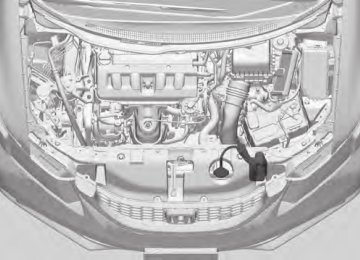
■ Jump Starting Procedure Turn off the power to electric devices, such as audio and lights. Turn off the engine, then open the hood. 1.8 ℓ engine models
1. Connect the first jumper cable to your
vehicle's battery + terminal.
2. Connect the other end of the first jumper
cable to the booster battery + terminal. u Use a 12-volt booster battery only.
3. Connect the second jumper cable to the
booster battery - terminal.
Booster Battery
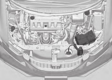
2.4 ℓ engine models
Booster Battery
1Jump Starting
3WARNING
A battery can explode if you do not follow the correct procedure, seriously injuring anyone nearby.
Keep all sparks, open flames, and smoking materials away from the battery.
Securely attach the jumper cables clips so that they do not come off when the engine vibrates. Also be careful not to tangle the jumper cables or allow the cable ends to touch each other while attaching or detaching the jumper cables.
Continued
331
4. Connect the other end of the second
1Jump Starting
Battery performance degrades in cold conditions and may prevent the engine from starting.
jumper cable to the engine mounting bolt as shown. Do not connect this jumper cable to any other part.
5. If your vehicle is connected to another
vehicle, start the assisting vehicle's engine and increase its rpm slightly.
6. Attempt to start your vehicle's engine. If it
turns over slowly, check that the jumper cables have good metal-to-metal contact.
uuJump Startingu
1.8 ℓ engine models
2.4 ℓ engine models
332
■ What to Do After the Engine Starts Once your vehicle's engine has started, remove the jumper cables in the following order.
1. Disconnect the jumper cable from your vehicle's ground. 2. Disconnect the other end of the jumper cable from the booster battery -
terminal.
3. Disconnect the jumper cable from your vehicle's battery + terminal. 4. Disconnect the other end of the jumper cable from the booster battery +
terminal.
Have your vehicle inspected by a nearby service station or a dealer.
uuJump Startingu
333
Shift Lever Does Not Move
Automatic transmission models Follow the procedure below if you cannot move the shift lever out of the (P position.
■ Releasing the Lock
1. Set the parking brake. 2. Remove the key from the ignition switch. 3. Wrap a cloth around the tip of a small flat-
tip screwdriver. Put it into the shift lock release slot as shown in the image, and remove the cover.
Slot
Cover
4. Insert the key into the shift lock release slot. 5. While pushing the key down, press the shift lever release button and place the shift lever into (N. u The lock is now released. Have the shift
lever checked by a dealer as soon as possible.
Release Button
Shift Lock Release Slot
334
Overheating
How to Handle Overheating Overheating symptoms are as follows: • The high temperature indicator comes on or the engine suddenly loses power. • Steam or spray comes out of the engine compartment.
■ First thing to do 1. Immediately park the vehicle in a safe place. 2. Turn off all accessories and turn on the hazard warning lights.
u No steam or spray present: Keep the engine running and open the hood. u Steam or spray is present: Turn off the engine and wait until it subsides.
Then open the hood.
1How to Handle Overheating
3WARNING
Steam and spray from an overheated engine can seriously scald you.
Do not open the hood if steam is coming out.
NOTICE Continuing to drive with the high temperature indicator on may damage the engine.
Continued
335
uuOverheatinguHow to Handle Overheating
■ Next thing to do
MAX
MIN
Reserve Tank
1. Check that the cooling fan is operating and stop the engine once the high temperature indicator goes off. u If the cooling fan is not operating,
immediately stop the engine.
2. Once the engine has cooled down, inspect
the coolant level and check the cooling system components for leaks. u If the coolant level in the reserve tank is
low, add coolant until it reaches the MAX mark.
u If there is no coolant in the reserve tank, check that the radiator is cool. Cover the radiator cap with a heavy cloth and open the cap. If necessary, add coolant up to the base of the filler neck, and put the cap back on.
1How to Handle Overheating
3WARNING
Removing the radiator cap while the engine is hot can cause the coolant to spray out, seriously scalding you.
Always let the engine and radiator cool down before removing the radiator cap.
If the coolant is leaking, contact a dealer for repairs.
Use water as an emergency/temporary measure only. Have a dealer flush the system with proper antifreeze as soon as possible.
■ Last thing to do Once the engine has cooled sufficiently, restart it and check the high temperature indicator. If the high temperature indicator is off, resume driving. If it stays on, contact a dealer for repairs.
336
Indicator, Coming On/Blinking
If the Low Oil Pressure Indicator Comes On
■ Reasons for the indicator to come on Comes on when the engine oil pressure is low. ■ What to do as soon as the indicator comes on 1. Immediately park the vehicle in a safe place. 2. If necessary, turn the hazard warning lights on. ■ What to do after parking the vehicle 1. Stop the engine and let it sit for about one minute. 2. Open the hood and check the oil level.
u Add oil as necessary.
3. Start the engine and check the low oil pressure indicator.
u The light goes out: Start driving again. u The light does not go out within 10 seconds: Stop the engine and
contact a dealer for repairs immediately.
If the Charging System Indicator Comes On
■ Reasons for the indicator to come on Comes on when the battery is not being charged. ■ What to do when the indicator comes on Turn off the heating and cooling system */climate control system *, rear defogger, and other electrical systems, and immediately contact a dealer for repairs.
1If the Low Oil Pressure Indicator Comes On
NOTICE Running the engine with low oil pressure can cause serious mechanical damage almost immediately.
1If the Charging System Indicator Comes On
If you need to stop temporarily, do not turn off the engine. Restarting the engine may rapidly discharge the battery.
* Not available on all models
337
uuIndicator, Coming On/BlinkinguIf the Malfunction Indicator Lamp Comes On or Blinks
If the Malfunction Indicator Lamp Comes On or Blinks
■ Reasons for the indicator lamp to come on or blink • Comes on when there is a problem with the engine emissions control
system, or the fuel fill cap is missing, or loose.
• Blinks when engine misfiring is detected. ■ What to do when the indicator lamp comes on Avoid high speeds and immediately get your vehicle inspected at a dealer. ■ What to do when the indicator lamp blinks Park the vehicle in a safe place with no flammable items and wait at least ten minutes or more with the engine stopped until it cools.
1If the Malfunction Indicator Lamp Comes On or Blinks
NOTICE If you drive with the malfunction indicator lamp on, the emissions control system and the engine could be damaged.
If the malfunction indicator lamp blinks again when restarting the engine, drive to the nearest dealer at 31 mph (50 km/h) or less. Have your vehicle inspected.
■ Check/Tighten Fuel Cap Message ■ The message appears on when: An evaporative system leak is detected. This may be caused by the fuel fill cap being loose or not being installed.
■ What to do when the message appears: 1. Stop the engine. 2. Check that the fuel fill cap is fully installed.
u If not, loosen the cap, and then retighten it until it clicks at least once.
3. Drive for several days of normal driving.
u The message should go off.
■ When the malfunction indicator lamp comes on Malfunction indicator lamp comes on if the system continues to detect a leak of gasoline vapor. If this happens, check the fuel fill cap using the procedures described above.
338
uuIndicator, Coming On/BlinkinguIf the Brake System Indicator Comes On
If the Brake System Indicator Comes On
U.S.
Canada
■ Reasons for the indicator to come on • The brake fluid is low. • There is a malfunction in the brake system. ■ What to do when the indicator comes on while driving Press the brake pedal lightly to check pedal pressure. • If normal, check the brake fluid level the next time you stop. • If abnormal, take immediate action. If necessary, downshift the
transmission to slow the vehicle using engine braking.
1If the Brake System Indicator Comes On
Have your vehicle repaired immediately. It is dangerous to drive with low brake fluid. If there is no resistance from the brake pedal, stop immediately in a safe place. If necessary downshift the gears.
If the brake system indicator and ABS indicator come on simultaneously, the electronic brake distribution system is not working. This can result in vehicle instability under sudden braking. Have your vehicle inspected by a dealer immediately.
If the EPS System Indicator Comes On
■ Reasons for the indicator to come on • Comes on when there is a problem with the EPS system. • If you depress the accelerator pedal repeatedly to increase the engine
speed while the engine is idling, the indicator comes on, and sometimes the steering wheel becomes harder to operate.
■ What to do when the indicator comes on Stop the vehicle in a safe place and restart the engine. If the indicator comes on and stays on, immediately have your vehicle inspected by a dealer.
1If the EPS System Indicator Comes On
NOTICE If you repeatedly turn the steering wheel at an extremely low speed, or hold the steering wheel on the full left or right position for a while, the system heats up. The system goes into a protective mode, and limits its performance. The steering wheel becomes harder and harder to operate. Once the system cools down, the EPS system is restored. Repeated operation under these conditions can eventually damage the system.
339
uuIndicator, Coming On/BlinkinguIf the Low Tire Pressure/TPMS Indicator Comes On or Blinks
U.S. models If the Low Tire Pressure/TPMS Indicator Comes On or Blinks
■ Reasons for the indicator to come on or blink A tire pressure is significantly low. If there is a problem with the TPMS or the compact spare tire * is installed, the indicator blinks for about one minute, and then stays on. ■ What to do when the indicator comes on Stop your vehicle in a safe place. Check the tire pressure and adjust the pressure to the specified level. The specified tire pressure is on a label on the driver side doorjamb. ■ What to do when the indicator blinks Have the tire inspected by a dealer as soon as possible. If the compact spare tire * causes the indicator to blink, change the tire to a full-size tire. The indicator goes off after driving for a few miles (kilometers).
1If the Low Tire Pressure/TPMS Indicator Comes On or Blinks
NOTICE Driving on an extremely underinflated tire can cause it to overheat. An overheated tire can fail. Always inflate your tires to the prescribed level.
340
* Not available on all models
Fuses
Fuse Locations If any electrical devices are not working, turn the ignition switch to LOCK (0 and check to see if any applicable fuse is blown.
■ Engine Compartment Fuse Box Located near the brake fluid reservoir. Push the tabs to open the box. Fuse locations are shown on the fuse box cover. Locate the fuse in question by the fuse number and box cover number.
■ Circuit protected and fuse rating
Circuit Protected
Circuit Protected
EPS −
ABS/VSA Motor ABS/VSA FSR
−
Main Fuse IG Main
Fuse Box Main Fuse Box Main 2
Headlight Main−
Rear Defogger
−
Blower
−
Sub Fan Motor Main Fan Motor
−
Amps 70 A
−
30 A 30 A
−
100 A 50 A 60 A 60 A 30 A
−
30 A
−
40 A
−
20 A 20 A
−
10
Left Headlight Low Beam
10 A 7.5 A Right Headlight Low Beam 10 A
ST MG
− − − −
− − − −
Oil Level
Fog Lights *
11
12
13 Driver’s Power Seat Sliding * 14
15
16Hazard FI Sub IG Coil
17
18
19
20
21
22
2324
25
26
27
28
29Stop
Horn
Premium Amp *
INJ IGP DBW H/L LO
Driver’s Power Seat
Reclining * MG Clutch
−
SMALL
Interior Lights
Backup
*1:1.8 ℓ models *2:2.4 ℓ models
Amps 7.5 A (20 A) (20 A) 10 A 15 A 15 A 15 A*1
10 A*2
10 A (20 A) (15 A) 15 A 15 A 20 A(20 A)
7.5 A
−
20 A 7.5 A 10 A
* Not available on all models
Continued
341
uuFusesuFuse Locations
■ Interior Fuse Box Located under the dashboard.
Fuse Label
Fuse locations are shown on the label on the side panel. Locate the fuse in question by the fuse number and label number.
■ Circuit protected and fuse rating
Circuit Protected
ACG SRS
Fuel Pump
HAC Option*
8 Door Lock Motor 2 (Unlock) 9 Door Lock Motor 1 (Unlock)
Power Window
VB SOL *
Meter
Amps (20 A) 10 A 10 A 15 A 7.5 A 7.5 A (15 A) 15 A 15 A
342
* Not available on all models
10
1112
13
1415
16
17
18
19
20
21
22
23
24
25
2627
28
2930
Circuit Protected
−
Moonroof *
Accessory Power Socket
(Center Console) *
−
Seat Heaters *
Driver’s Door Lock Motor
(Unlock) *
− − −
ACC
ACC Key Lock
Daytime Running Lights
HAC HAC*
ABS/VSA
− −
Accessory Power Socket
(Front) Washer
ODS
Driver’s Door Lock Motor
(Lock) *
31
32 Door Lock Motor 2 (Lock)−
Amps
−
(20 A)
(20 A)
−
(15 A)
(10 A)
− − −
7.5 A 7.5 A 7.5 A 7.5 A (7.5 A) 7.5 A
− −
20 A
15 A 7.5 A
(10 A)
−
15 A
Circuit Protected
Amps 15 A 7.5 A 7.5 A
− −
Small Lights Illumination
33 Door Lock Motor 1 (Lock) 34
35
36
37
10 A 38
39 Right Headlight High Beam 10 A (7.5 A) 40
20 A 41
42
20 ALeft Headlight High Beam
Door Lock
TPMS *
Driver’s Power Window Rear Passenger’s Side
− −
43
44
45
46
−Power Window
Front Passenger’s Side
Power Window
Rear Driver’s Side Power
Window Wiper STS *
(20 A)
20 A
(20 A)
30 A (7.5 A)
uuFusesuInspecting and Changing Fuses
Inspecting and Changing Fuses
1. Turn the ignition switch to LOCK (0. Turn
1Inspecting and Changing Fuses
Blown Fuse
headlights and all accessories off.
2. Remove the fuse box cover. 3. Check the large fuse in the engine
compartment. u If the fuse is blown, use a Phillips-head
screwdriver to remove the screw and replace it with a new one.
4. Inspect the small fuses in the engine compartment and the vehicle interior. u If there is a burned out fuse, remove it
with the fuse puller and replace it with a new one.
NOTICE Replacing a fuse with one that has a higher rating greatly increases the chances of damaging the electrical system.
Replace fuse with a spare fuse of the same specified amperage. Confirm the specified amperage using the charts on P. 341 to 342.
There is a fuse puller on the back of the engine compartment fuse box cover.
Combined Fuse
Fuse Puller
343
Emergency Towing
Call a professional towing service if you need to tow your vehicle.
1Emergency Towing
■ Flat bed equipment The operator loads your vehicle on the back of a truck. This is the best way to transport your vehicle.
■ Wheel lift equipment The tow truck uses two pivoting arms that go under the front tires and lift them off the ground. The rear tires remain on the ground. This is an acceptable way to tow your vehicle.
NOTICE Trying to lift or tow your vehicle by the bumpers will cause serious damage. The bumpers are not designed to support the vehicle's weight.
NOTICE Improper towing such as towing behind a motorhome or other motor vehicle can damage the transmission.
Never tow your vehicle with just a rope or chain. It is very dangerous, since ropes or chains may shift from side to side or break.
344
Information
This chapter includes your vehicle's specifications, locations of identification numbers, and other information required by regulation.
Specifications .................................... 346
Identification NumbersVehicle Identification Number (VIN)...... 350
Engine Number and Transmission Number...................................... 350
Devices that Emit Radio Waves ....... 351
Reporting Safety Defects ................. 352Emissions Testing
Testing of Readiness Codes.............. 353
Warranty Coverages ........................ 355
Authorized Manuals......................... 357
Customer Service Information......... 358345
■ Light Bulbs Headlights (Low Beam) Headlights (High Beam) Fog Lights * Front Turn Signal/Parking/Side Marker Lights Brake/Taillights Rear Turn Signal Lights Rear Side Marker Lights Back-Up Lights Taillights High-Mount Brake Light Rear License Plate Lights Trunk Light Interior Lights
51W (HB4) 60W (HB3) 55W (H11)
28/8W
21/5W 21W (Amber) LED 16W 3CP 21W 5W 5W
Map Lights Ceiling Light
8W 8W
Specifications
Honda Civic 4-Door
1.8 ℓ engine models ■ Vehicle Specifications Model No. of Passengers: Front Rear Total Weights: Gross Vehicle Weight Rating
U.S.: 3,660 lbs (1,660 kg)*1
Canada: 1,660 kg*1
U.S.: 3,792 lbs (1,720 kg)*2
Canada: 1,720 kg*2■ Engine Specifications Displacement
110 cu-in (1,798 cm3) NGK DENSO
DILZKR7B11GS DXU22HCR-D11S
Spark Plugs
■ Fuel Fuel: Type Fuel Tank Capacity ■ Battery Capacity/Type ■ Washer Fluid
Unleaded gasoline, Pump octane number of 87 or higher 13.2 US gal (50 ℓ)
38AH(5)/47AH(20)
Tank Capacity
U.S.: 2.6 US qt (2.5 ℓ) Canada: 4.8 US qt (4.5 ℓ)
Gross Axle Weight Rating (Front)
Gross Axle Weight Rating (Rear)
U.S.: 1,985 lbs (900 kg)*1
Canada: 900 kg*1
U.S.: 2,029 lbs (920 kg)*2
Canada: 920 kg*2U.S.: 1,742 lbs (790 kg)*1
Canada: 790 kg*1
U.S.: 1,786 lbs (810 kg)*2
Canada: 810 kg*2Air Conditioning: Refrigerant Type Charge Quantity Lubricant Type *1: LX, HF and Canadian DX models *2: EX, U.S. EX-L and Canadian Touring models
HFC-134a (R-134a) 13.2 – 15.0 oz (375 – 425 g) SP-10
346
* Not available on all models
■ Brake/Clutch Fluid Specified ■ Automatic Transmission Fluid
Honda Heavy Duty Brake Fluid DOT 3
Specified
Honda ATF DW-1
(automatic transmission fluid) ChangeCapacity ■ Manual Transmission Fluid Specified Capacity
Honda Manual Transmission Fluid Change
1.5 US qt (1.4 ℓ)
2.5 US qt (2.4 ℓ)
■ Engine Oil
Capacity
Recommended
3.7 US qt (3.5 ℓ)
·Genuine Honda Motor Oil 0W-20
·API Premium-grade 0W-20 detergent oil Change Change including filter ■ Engine Coolant Specified RatioHonda Long-Life Antifreeze/Coolant Type2
50/50 with distilled water 1.48 US gal (5.59 ℓ) (change including the remaining 0.125 US gal (0.475 ℓ) in the reserve tank)3.9 US qt (3.7 ℓ)
Capacity
uuSpecificationsu
P195/65R15 89H*1, *2
P195/65R15 89S*3
P205/55R16 89H*4
P215/45R17 87V*5
30 (210 [2.1])*1, *2
32 (220 [2.2])*3, *4, *5
T135/80D15 99M60 (420 [4.2])
15 x 6J*1, *3
15 x 6 1/2J*2
16 x 6 1/2J*4
17 x 7J*5
15 x 4T■ Tire
Size
Regular
Pressure psi(kPa[kgf/cm2]) Size Pressure psi(kPa[kgf/cm2])
Compact Spare *
Wheel Size
Regular
Compact Spare *
*1: Canadian DX models *2: LX models *3: HF model *4: EX and U.S. EX-L models *5: Canadian Touring models
* Not available on all models
Continued
347
■ Engine Specifications Displacement
144 cu-in (2,354 cm3) NGK DENSO
ILZKR7B-11S SXU22HCR11S
Spark Plugs
■ Fuel Fuel: Type Fuel Tank Capacity ■ Battery Capacity/Type ■ Washer Fluid
Unleaded premium gasoline, Pump octane number of 91 or higher 13.2 US gal (50 ℓ)
38AH(5)/47AH(20)
Tank Capacity
U.S.: 2.6 US qt (2.5 ℓ) Canada: 4.8 US qt (4.5 ℓ)
■ Light Bulbs Headlights (Low Beam) Headlights (High Beam) Fog Lights Front Turn Signal/Parking/Side Marker Lights Brake/Taillights Rear Turn Signal Lights Rear Side Marker Lights Back-Up Lights Taillights High-Mount Brake Light Rear License Plate Lights Trunk Light Interior Lights
51W (HB4) 60W (HB3) 35W (H8)
28/8W
21/5W 21W (Amber) LED 16W 3CP LED 5W 5W
Map Lights Ceiling Light
8W 8W
uuSpecificationsu
Honda Civic 4-Door
2.4 ℓ engine models ■ Vehicle Specifications Model No. of Passengers: Front Rear Total Weights: Gross Vehicle Weight Rating Gross Axle Weight Rating (Front)
U.S.: 3,925 lbs (1,780 kg) Canada: 1,780 kg
U.S.: 2,117 lbs (960 kg) Canada: 960 kg
Gross Axle Weight Rating (Rear)
Air Conditioning: Refrigerant Type Charge Quantity Lubricant Type
U.S.: 1,830 lbs (830 kg) Canada: 830 kg
HFC-134a (R-134a) 13.2 – 15.0 oz (375 – 425 g) SP-10
348
■ Brake/Clutch Fluid Specified ■ Manual Transmission Fluid Specified Capacity
Honda Manual Transmission Fluid Change
Honda Heavy Duty Brake Fluid DOT 3
2.0 US qt (1.9 ℓ)
■ Engine Oil
Capacity
Recommended
4.2 US qt (4.0 ℓ)
·Genuine Honda Motor Oil 0W-20
·API Premium-grade 0W-20 detergent oil Change Change including filter ■ Engine Coolant Specified RatioHonda Long-Life Antifreeze/Coolant Type2
50/50 with distilled water 1.45 US gal (5.5 ℓ) (change including the remaining 0.125 US gal (0.475 ℓ) in the reserve tank)4.4 US qt (4.2 ℓ)
Capacity
uuSpecificationsu
■ Tire
Regular
Compact Spare
Wheel Size
Size
Pressure psi(kPa[kgf/cm2]) Size Pressure psi(kPa[kgf/cm2]) Regular Compact Spare
P215/45R17 87V 215/45ZR17 91W*1
32 (220 [2.2])
T135/80D16 101M
60 (420 [4.2])
17 x 7J 16 x 4T
*1: Optional for U.S. models (summer tires)
349
Identification Numbers