- Download PDF Manual
-
transmission
CAUTIONS
Do not tow your vehicle faster than 50 km/h (30 mph) or further than 50
kilometres (30 miles). If a speed of 50 km/h (30 mph) and a distance of 50 kilometres (30 miles) is to be exceeded the drive wheelsmust be lifted clear of the ground.
In the event of a mechanical failure of the transmission the drive wheels must be lifted clear of the ground. Do not tow your vehicle backwards.
Select neutral when your vehicle is being towed.
99
E87280 Maintenance
•
Check when refuelling •
Engine oil level. See Engine Oil Check (page 107). Brake fluid level. See Brake and Clutch Fluid Check (page 108).
• Washer fluid level. See Washer Fluid
Check (page 109). Tyre pressures (when cold). See Technical Specifications (page 125). Tyre condition. See Tyre Care (page 124).
•
•
Monthly checks •
Engine coolant level (engine cold). See Engine Coolant Check (page 107). • Pipes, hoses and reservoirs for leaks. • Power steering fluid level. See Power
Steering Fluid Check (page 108).
• Air conditioning operation. • Parking brake operation. • Horn operation. •
Tightness of wheel nuts. See Technical Specifications (page 125).
GENERAL INFORMATION Have your vehicle serviced regularly to help maintain its roadworthiness and resale value. There is a large network of Ford Authorised Repairers that are there to help you with their professional servicing expertise. We believe that their specially trained technicians are best qualified to service your vehicle properly and expertly. They are supported by a wide range of highly specialised tools developed specifically for servicing your vehicle. In addition to regular servicing, we recommend that you carry out the following additional checks. WARNINGS
Switch the ignition off before touching or attempting adjustment of any kind. Do not touch the electronic ignition system parts after you have switched the ignition on or when the engine is
running. The system operates at high voltage.
Keep your hands and clothing clear of the engine cooling fan. Under certain conditions, the fan may
continue to run for several minutes after you have switched the engine off.
CAUTION
When carrying out maintenance checks, make sure that filler caps are fitted securely.
Daily checks • • • Warning lamps and indicators.
Exterior lamps. Interior lamps.
100
Maintenance
OPENING AND CLOSING THE BONNET Opening the bonnet
2. Raise the bonnet slightly and pull the
catch towards you.
1. Pull the lever.
3. Open the bonnet and support it with
the strut.
Closing the bonnet Note: Make sure that the bonnet is closed properly. Lower the bonnet and allow it to drop from under its own weight for the last 20 – 30
centimetres.101
E9041312E9041454E78143 Maintenance
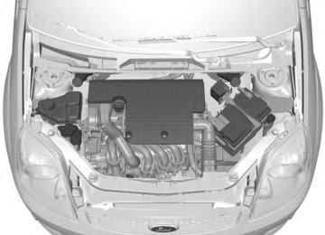
UNDER BONNET OVERVIEW - 1.25L DURATEC-16V (SIGMA)/1.4L DURATEC-16V (SIGMA)/1.6L DURATEC-16V (SIGMA)
Engine coolant reservoir*: See Engine Coolant Check (page 107). Brake and clutch fluid reservoir (right-hand drive)*: See Brake and Clutch Fluid Check (page 108). Engine oil filler cap*: See Engine Oil Check (page 107). Engine compartment fuse box. See Fuses (page 96).
102
ABCDFEGHJIE90583 Maintenance
Brake and clutch fluid reservoir (left-hand drive)*: See Brake and Clutch Fluid Check (page 108). Battery: No maintenance necessary. Windscreen and rear window washer fluid reservoir: See Washer Fluid Check (page 109). Air cleaner: No maintenance necessary. Engine oil dipstick*: See Engine Oil Check (page 107). Power steering fluid reservoir: See Power Steering Fluid Check (page 108).
* The filler caps and the engine oil dipstick are coloured for easy identification.
103
Maintenance
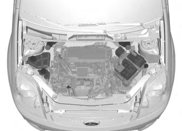
UNDER BONNET OVERVIEW - 1.4L DURATORQ-TDCI (DV) DIESEL
Engine coolant reservoir*: See Engine Coolant Check (page 107). Brake and clutch fluid reservoir (right-hand drive)*: See Brake and Clutch Fluid Check (page 108). Engine oil filler cap*: See Engine Oil Check (page 107). Engine compartment fuse box. See Fuses (page 96). Brake and clutch fluid reservoir (left-hand drive)*: See Brake and Clutch Fluid Check (page 108). Battery: No maintenance necessary.
104
ABCDFEGHJIE90585 Maintenance
Windscreen and rear window washer fluid reservoir: See Washer Fluid Check (page 109). Air cleaner: No maintenance necessary. Engine oil dipstick*: See Engine Oil Check (page 107). Power steering fluid reservoir: See Power Steering Fluid Check (page 108).
* The filler caps and the engine oil dipstick are coloured for easy identification.
UNDER BONNET OVERVIEW - 1.6L DURATORQ-TDCI (DV) DIESEL
105
ABCDFEGHKIJE90586 Maintenance
Engine coolant reservoir*: See Engine Coolant Check (page 107). Brake and clutch fluid reservoir (right-hand drive)*: See Brake and Clutch Fluid Check (page 108). Engine oil filler cap*: See Engine Oil Check (page 107). Engine compartment fuse box. See Fuses (page 96). Brake and clutch fluid reservoir (left-hand drive)*: See Brake and Clutch Fluid Check (page 108). Battery: No maintenance necessary. Windscreen and rear window washer fluid reservoir (left-hand drive): See Washer Fluid Check (page 109). Air cleaner: No maintenance necessary. Engine oil dipstick*: See Engine Oil Check (page 107). Power steering fluid reservoir: See Power Steering Fluid Check (page 108). Windscreen and rear window washer fluid reservoir (right-hand drive): See Washer Fluid Check (page 109).
* The filler caps and the engine oil dipstick are coloured for easy identification.
ENGINE OIL DIPSTICK - 1.25L DURATEC-16V (SIGMA)/1.4L DURATEC-16V (SIGMA)/1.6L DURATEC-16V (SIGMA)
ENGINE OIL DIPSTICK - 1.4L DURATORQ-TDCI (DV) DIESEL
MIN MAX
MIN MAX
106
E95540BAE95911AB Maintenance
ENGINE OIL DIPSTICK - 1.6L DURATORQ-TDCI (DV) DIESEL
MIN MAX
ENGINE OIL CHECK CAUTION
Do not use oil additives or other engine treatments. Under certain conditions, they could damage the
engine.
Note: The oil consumption of new engines reaches its normal level after approximately 5000 kilometres (3000 miles). Checking the oil level CAUTION
Make sure that the level is between the MIN and the MAX marks.
Note: Check the level before starting the engine. Note: Make sure that your vehicle is on level ground. Note: Oil expands when it is hot. The level may therefore extend a few millimetres beyond the MAX mark.
Remove the dipstick and wipe it with a clean, lint free cloth. Replace the dipstick and remove it again to check the oil level. If the level is at the MIN mark, top up immediately. Topping up
WARNINGS
Only top up when the engine is cold. If the engine is hot, wait 10 minutes for the engine to cool down. Do not remove the filler cap when the engine is running.
Remove the filler cap.
CAUTION
Do not top up further than the MAX mark.
Top up with fluid that meets the Ford specification. See Technical Specifications (page 109). Replace the filler cap. Turn it until you feel a strong resistance. ENGINE COOLANT CHECK Checking the coolant level
WARNING
Do not allow the fluid to touch your skin or eyes. If this happens, rinse the affected areas immediately with
plenty of water and contact your doctor.
CAUTION
Make sure that the level is between the MIN and the MAX marks.
107
E90983AB Maintenance
POWER STEERING FLUID CHECK
WARNING
Do not allow the fluid to touch your skin or eyes. If this happens, rinse the affected areas immediately with
plenty of water and contact your doctor.
CAUTION
Make sure that the level is between the MIN and the MAX marks.
If the level is at the MIN mark, top up immediately. Topping up Remove the filler cap.
CAUTION
Do not top up further than the MAX mark.
Top up with fluid that meets the Ford specification. See Technical Specifications (page 109). BRAKE AND CLUTCH FLUID CHECK
WARNINGS
Do not allow the fluid to touch your skin or eyes. If this happens, rinse the affected areas immediately with
plenty of water and contact your doctor. If the level is at the MIN mark, have the system checked by a properly trained technician as soon as
possible.
Note: Coolant expands when it is hot. The level may therefore extend beyond the MAX mark. If the level is at the MIN mark, top up immediately. Topping up
WARNINGS
Only top up when the engine is cold. If the engine is hot, wait 10 minutes for the engine to cool down. Do not remove the filler cap when the engine is running. Do not remove the filler cap when the engine is hot. Wait for the engine to cool down. Undiluted coolant is flammable and may ignite if spilt on a hot exhaust.
CAUTIONS
In an emergency, you can add just water to the cooling system to reach a vehicle service station. Have the system checked by a properly trained technician as soon as possible.
Prolonged use of incorrect dilution of the coolant can cause engine damage from corrosion, overheating or
freezing.
Unscrew the cap slowly. Any pressure will escape slowly as you unscrew the cap.
CAUTION
Do not top up further than the MAX mark.
Top up with a 50/50 mixture of coolant and water using fluid that meets the Ford specification. See Technical Specifications (page 109).
108
Maintenance
Note: Contamination with dirt, water, petroleum products or other materials may result in brake failure or costly repairs. Note: The brake and the clutch systems are supplied from the same reservoir. Top up with fluid that meets the Ford specification. See Technical Specifications (page 109).
WASHER FLUID CHECK Note: The front and rear washer systems are supplied from the same reservoir. When topping up, use a mixture of washer fluid and water to help prevent freezing in cold weather and improve the cleaning capability. We recommend that you use only high quality washer fluid. For information on fluid dilution, refer to the product instructions.
TECHNICAL SPECIFICATIONS Vehicle fluids
Item
Engine oil
Specification WSS-M2C913-C
Power steering fluid
WSS-M2C204-A2
Antifreeze
WSS-M97B44-D
Recommended fluid
Castrol Engine Oil* Ford or Motorcraft Power Steering Fluid Motorcraft SuperPlus Anti- freeze Ford or Motorcraft Super DOT 4 Brake Fluid
WSS-M6C57-A2
Brake fluid * Providing it meets the specification defined by WSS-M2C913-C, you can also use Ford Engine Oil or an alternative engine oil. Topping up the oil: If you are unable to find an oil that meets the specification defined by WSS-M2C913-C, you must use SAE 5W-30 (preferred),SAE 5W-40 (except vehicles with E85 fuel) or SAE 10W-40 that meets the specification defined by either ACEA A5/B5 (preferred) or ACEA A3/B3. Using these oils can result in longer engine cranking periods, reduced engine performance, reduced fuel economy and increased emission levels.
CAUTION
Do not use oils which do not meet the specifications or requirements. Use of unsuitable oil may lead to engine damage which is not covered by the Ford Warranty.
Note: If you operate your vehicle in temperatures below -20°C (68°F), you must not use SAE 10W-40 engine oil. Castrol engine oil recommended.
109
Maintenance
Capacities
Variant
Item
Capacity in Litres (gallons)
All
All
Petrol Diesel
1.25L Duratec
1.25L Duratec
1.25L Duratec
1.25L Duratec
1.4L Duratec
1.4L Duratec
1.4L Duratec
1.4L Duratec
1.6L Duratec
1.6L Duratec
MAX mark
2.5 (0.5)
45 (9.9) 43 (9.5)
3.75 (0.8)
3.8 (0.8)
3.5 (0.8)
5 (1.1)
3.75 (0.8)
3.8 (0.8)
3.5 (0.8)
5 (1.1)
4.1 (0.9)
4.25 (0.9)
Power steering system Windscreen and rear window washer system Fuel tank Fuel tank Engine lubrication system - including the oil filter (EFL500) Engine lubrication system - including the oil filter (EFL10) Engine lubrication system - excluding the oil filter Engine cooling system Engine lubrication system - including the oil filter (EFL500) Engine lubrication system - including the oil filter (EFL10) Engine lubrication system - excluding the oil filter Engine cooling system Engine lubrication system - including the oil filter (EFL10) Engine lubrication system - including the oil filter (EFL600)
110
E115472 Maintenance
Variant
Item
Capacity in Litres (gallons)
1.6L Duratec
1.6L Duratec
1.4L Duratorq-TDCi
1.4L Duratorq-TDCi
1.4L Duratorq-TDCi
1.6L Duratorq-TDCi
1.6L Duratorq-TDCi
1.6L Duratorq-TDCi
Engine lubrication system - excluding the oil filter Engine cooling system Engine lubrication system - including the oil filter Engine lubrication system - excluding the oil filter Engine cooling system Engine lubrication system - including the oil filter Engine lubrication system - excluding the oil filter Engine cooling system
3.75 (0.8)
5 (1.1)
3.8 (0.8)
3.4 (0.8)
5.5 (1.2)
3.85 (0.8)
3.45 (0.8)
6 (1.3)
111
Vehicle care
CLEANING THE EXTERIOR
Cleaning the chrome trim
CAUTION
Do not use abrasives or chemical solvents. Use soapy water.
Body paintwork preservation
CAUTIONS
Do not polish your vehicle in strong sunshine. Do not allow polish to touch plastic surfaces. It could be difficult to remove. Do not apply polish to the windscreen or rear window. This could cause the wipers to become noisy and they may
not clear the window properly.
We recommend that you wax the paintwork once or twice a year. CLEANING THE INTERIOR Seat belts
WARNINGS
Do not use abrasives, or chemical solvents to clean them. Do not allow moisture to penetrate the seat belt retractor mechanism.
Clean the seat belts with interior cleaner or water applied with a soft sponge. Let the seat belts dry naturally, away from artificial heat.
WARNING
If you use a car wash with a waxing cycle, make sure that you remove the wax from the windscreen.
CAUTIONS
Prior to using a car wash facility check the suitability of it for your vehicle. Some car wash installations use water at high pressure. This could damage certain parts of your vehicle. Remove the aerial before using an automatic car wash. Switch the heater blower off to prevent contamination of the fresh air filter.
We recommend that you wash your vehicle with a sponge and lukewarm water containing a car shampoo. Cleaning the headlamps
CAUTIONS
Do not scrape the headlamp lenses or use abrasives, alcoholic solvents or chemical solvents to clean them. Do not wipe the headlamps when they are dry.
Cleaning the rear window
CAUTION
Do not scrape the inside of the rear window or use abrasives or chemical solvents to clean it.
Use a clean, lint free cloth or a damp chamois leather to clean the inside of the rear window.
112
Vehicle care
Instrument cluster screens, LCD screens, radio screens WARNING
Do not use abrasives, alcoholic solvents or chemical solvents to clean them. Rear windows
CAUTIONS
Do not use any abrasive materials to clean the interior of the rear windows. Do not install stickers or labels to the interior of the rear windows.
REPAIRING MINOR PAINT DAMAGE
CAUTION
Remove apparently harmless looking substances from the paintwork immediately (e.g. bird droppings, tree resins, insect remains, tar spots, road salt and industrial fall out).
You should repair paintwork damage caused by stones from the road or minor scratches as soon as possible. A choice of products is available from your Ford Dealer. Read and follow the manufacturer’s instructions.
113
Vehicle battery
JUMP-STARTING THE VEHICLE
To connect the booster cables
CAUTIONS
Connect batteries with only the same nominal voltage. Always use booster cables with insulated clamps and adequate size cable. Do not disconnect the battery from the vehicle’s electrical system.
Flat battery vehicle Booster battery vehicle Positive connection cable Negative connection cable
114
E90587ABDC Vehicle battery
3. Run both vehicles for a minimum of
three minutes before disconnecting the leads.
CAUTION
Do not switch on the headlamps when disconnecting the cables. The peak voltage could blow the bulbs.
Disconnect the cables in the reverse order.
Vehicles with a petrol engine
CAUTIONS
Do not connect to the negative (–) terminal of the flat battery. Make sure that the jump leads are clear of any moving parts.
1. Position the vehicles so that they do
not touch one another.
2. Switch off the engine and any electrical
equipment.
3. Connect the positive (+) terminal of
vehicle A with the positive (+) terminal of vehicle B (cable C).
4. Connect the negative (-) terminal of vehicle B to the engine block or engine mount of vehicle A (cable D), as far from the battery as possible. Vehicles with a diesel engine
CAUTIONS
Do not connect to the negative (–) terminal of the flat battery. Make sure that the jump leads are clear of any moving parts.
1. Position the vehicles so that they do
not touch one another.
2. Switch off the engine and any electrical
equipment.
3. Connect the positive (+) terminal of
vehicle A with the positive (+) terminal of vehicle B (cable C).
4. Connect the negative (-) terminal of
vehicle B to the turbocharger of vehicle A (cable D).
To start the engine 1. Run the engine of vehicle B at
moderately high speed.
2. Start the engine of vehicle A.
115
Wheels and Tyres
Vehicles with a temporary spare wheel
WARNINGS
If the spare wheel differs from the other fitted wheels, these rules must be followed: Do not exceed 80 km/h (50 mph).
Drive the shortest possible distances.
Do not fit more than one spare wheel on your vehicle at any one time. Do not use snow chains on this type of wheel.
Note: Your vehicle may exhibit some unusual driving characteristics. Vehicle jack
WARNINGS
The vehicle jack supplied with your vehicle should only be used when changing a wheel in emergency
situations.
Before using the vehicle jack, check that it is not damaged or deformed and that the thread is lubricated and
free from foreign matter.
Never place anything between the jack and the ground, or the jack and the vehicle.
Note: Vehicles with a tyre repair kit are not equipped with a vehicle jack or a wheel brace. It is recommended to use a workshop type hydraulic jack for changing between summer and winter tyres.
GENERAL INFORMATION
CAUTIONS
Use only approved wheel and tyre sizes. Using other sizes could damage the vehicle and will make the National
Type Approval invalid.
If you change the diameter of the tyres from that fitted at the factory, the speedometer may not display the correct speed. Take the vehicle to your dealer to have the engine management system reprogrammed.
A decal with tyre pressure data is located in the driver’s door opening at the B-pillar. Check and set the tyre pressure at the ambient temperature in which you are intending to drive the vehicle and when the tyres are cold. Tyre pressures
WARNING
If the vehicle is used with a roof load or is fully laden the tyres must be set to the full load tyre pressure settings.
Driving at normal tyre pressures will improve ride comfort; however it will alter the driving characteristics and fuel consumption of the vehicle. For optimum dynamic performance the recommended tyre pressure setting is 2.4
bar (35 psi) front and 2.2 bar (32 psi) rear. CHANGING A ROAD WHEEL Locking wheel nuts You can obtain a replacement locking wheel nut key and replacement locking wheel nuts from your dealer using the reference number certificate.116
Wheels and Tyres
Note: Use a jack with a minimum lifting capacity of 1.5 tonnes and a lifting plate with a minimum diameter of 80 millimetres (3.1
inches). Your vehicle jack, wheel brace, screw-in towing eye and wheel trim remover are located in the spare wheel well.Jacking and lifting points
CAUTION
Use only the specified jacking points. If you use other positions, you may damage the body, steering,
suspension, engine, braking system or the fuel lines.
Emergency use only Maintenance
117
E92658AB Wheels and Tyres
Assembling the wheel brace Type one
WARNING
When returning the wheel brace extension to its original position, take care not to get your fingers caught.
Indentations in the sills A show the location of the jacking points.
Note: Make sure that the wheel brace is fully extended.
Extend the wheel brace. Type two
CAUTION
The screw-in towing eye has a left-hand thread. Turn it anti-clockwise to install it. Make sure
that the towing eye is fully tightened.
Note: If your vehicle is fitted with side skirts, remove the cover before positioning the vehicle jack.
Insert the screw-in towing eye into the wheel brace.
118
E93184AE92932E93020E122546E122502 Wheels and Tyres
WARNINGS
If your vehicle has a manual transmission, select first or reverse gear. If it has an automatic
transmission, select park.
If your vehicle is fitted with a Durashift EST transmission, select a gear before switching off the ignition. Have the passengers leave the vehicle. Secure the diagonally opposite wheel with an appropriate block or wheel chock. Make sure that the arrows on directional tyres point in the direction of rotation when the vehicle is
moving forwards. If you have to fit a spare wheel with the arrows pointing in the opposite direction, have the tyre refitted in the correct direction by a properly trained technician.
Do not work underneath the vehicle when it is supported only by a jack. Make sure the jack base is flat on the ground and vertically below the jacking point.
CAUTION
Do not lay alloy wheels face down on the ground, this will damage the paint.
Note: The spare wheel is located under the floor cover in the luggage compartment.
Removing the wheel trim Type one Insert the flat end of the wheel brace between the rim and the trim and carefully remove the trim. Type two
Insert the wheel trim remover.
1. 2. Remove the wheel trim. Note: Make sure that you pull the wheel trim remover at right angles to the trim. Removing a road wheel WARNINGS
Park your vehicle in such a position that neither the traffic nor you are hindered or endangered. Set up a warning triangle.
Make sure that the vehicle is on firm, level ground with the wheels pointing straight ahead. Switch off the ignition and apply the parking brake.
119
E12231421 Wheels and Tyres
WARNINGS
Do not fit run flat tyres on vehicles that were not originally fitted with them. Please contact your dealer for
more details regarding compatibility.
Make sure that the arrows on directional tyres point in the direction of rotation when the vehicle is
moving forwards. If you have to fit a spare wheel with the arrows pointing in the opposite direction, have the tyre refitted in the correct direction by a properly trained technician.
CAUTION
Do not install alloy wheels using wheel nuts designed for use with steel wheels.
Note: Make sure the wheel and hub contact surfaces are free from foreign matter. Note: Make sure that the cones on the wheel nuts are against the wheel. 1. 2. 3.
Install the wheel. Install the wheel nuts finger tight. Install the locking wheel nut key.
Install the jack to the flange.
Install the locking wheel nut key.
1. 2. Slacken the wheel nuts. 3. 4. Extend the jack until the base of the jack is flat on the ground, vertically below the jacking point. Jack up the vehicle until the tyre is clear of the ground.
5.
6. Remove the wheel nuts and the wheel. Installing a road wheel WARNINGS
Use only approved wheel and tyre sizes. Using other sizes could damage the vehicle and will make the National Type Approval invalid. See Technical Specifications (page 125).
4. Partially tighten the wheel nuts in the
sequence shown.
120
E121887121234E90589 Wheels and Tyres
5. Lower the vehicle and remove the jack. 6. Fully tighten the wheel nuts in the sequence shown. See Technical Specifications (page 125). Install the wheel trim using the ball of your hand.
7.
TYRE REPAIR KIT Your vehicle may not have a spare tyre. In this case it will have an emergency tyre repair kit that can be used to repair one flat tyre. The tyre repair kit is located in the spare wheel well. General information
WARNINGS
Depending on the type and extent of tyre damage, some tyres can only be partially sealed or not sealed at all.
Loss of tyre pressure can affect vehicle handling, leading to loss of vehicle control.
Do not use the tyre repair kit if the tyre has already been damaged as a result of being driven under inflated. Do not use the tyre repair kit on run flat tyres. Do not try to seal damage other than that located within the visible tread of the tyre. Do not try to seal damage to the tyre’s sidewall.
The tyre repair kit seals most tyre punctures [with a diameter of up to six millimetres (1/4 inch)] to temporarily restore mobility. Observe the following rules when using the kit:
•
•
• Drive with caution and avoid
making sudden steering or driving manoeuvres, especially if the vehicle is heavily loaded or you are towing a trailer. The kit will provide you with an emergency temporary repair, enabling you to continue your journey to the next vehicle or tyre dealer, or to drive a maximum distance of 200 kilometres (125 miles).
• Do not exceed a maximum speed of
80 km/h (50 mph). Keep the kit out of the reach of children.
• Only use the kit when the ambient
temperature is between –30°C (-22°F) and +70°C (+158°F).
Using the tyre repair kit WARNINGS
Compressed air can act as an explosive or propellant. Never leave the tyre repair kit unattended while in use.
CAUTION
Do not keep the compressor operating for more than 10 minutes.
Note: Use the tyre repair kit only for the vehicle with which it was supplied. • Park your vehicle at the roadside so that you do not obstruct the flow of traffic and so that you are able to use the kit without being in danger.
• Apply the parking brake, even if you have parked on a level road, to make sure that the vehicle will not move. • Do not attempt to remove foreign
objects like nails or screws penetrating the tyre.
121
Wheels and Tyres
•
Leave the engine running while the kit is in use, but not if the vehicle is in an enclosed or poorly ventilated area (for example, inside a building). In these circumstances, switch the compressor on with the engine turned off.
•
• Replace the sealant bottle with a new one before the expiry date (see top of bottle) is reached. Inform all other users of the vehicle that the tyre has been temporarily sealed with the tyre repair kit and make them aware of the special driving conditions to be observed.
Inflating the tyre
WARNINGS
Check the sidewall of the tyre prior to inflation. If there are any cracks, bumps or similar damage, do not
attempt to inflate the tyre.
Do not stand directly beside the tyre while the compressor is pumping. Watch the sidewall of the tyre. If any cracks, bumps or similar damage appear, turn off the compressor and let the air out by means of the pressure relief valve I. Do not continue driving with this tyre.
The sealant contains natural rubber latex. Avoid contact with skin and clothing. If this happens, rinse the
affected areas immediately with plenty of water and contact your doctor.
If the tyre inflation pressure does not reach 1.8 bar (26 psi) within 10
minutes, the tyre may have sufferedexcessive damage, making a temporary repair impossible. In this case, do not continue driving with this tyre.
Label Sealant bottle Sealant bottle hose Bottle holder Pressure gauge Power plug with cable Compressor switch Repair kit hose Pressure relief valve
1. Remove the tyre repair kit from the
wrapping.
122
E102881ABCDEFGHI Wheels and Tyres
2. Peel off the label A showing the maximum permissible speed of 80 km/h (50 mph) from the sealant bottle and attach it to the instrument panel in the driver’s field of view. Make sure the label does not obscure anything important.
3. Take the hose H with the pressure
relieve valve I and the power plug with cable F out of the kit.
4. Connect the hose H with the pressure relieve valve I to the sealant bottle B. 5. Engage the sealant bottle B into the
bottle holder D.
6. Remove the valve cap from the
damaged tyre.
7. Screw the sealant bottle hose C firmly
onto the valve of the damaged tyre.
8. Make sure that the compressor switch
G is in position 0. Insert the power plug F into the cigar lighter socket or auxiliary power socket. See Cigar Lighter (page 69).
9.
10. Start the engine. 11. Move the compressor switch G to
position 1. Inflate the tyre for no longer than 10
minutes to an inflation pressure of minimum 1.8 bar (26 psi) and a maximum of 3.5 bar (51 psi). Move the compressor switch G to position 0 and check the current tyre pressure with pressure gauge E.Note: If a tyre pressure of 1.8 bar (26 psi) is not reached do not continue. Note: When pumping in the sealant through the tyre valve, the pressure may rise up to 6 bar (87 psi) but will drop again after about 30 seconds. 13. Remove the power plug F from the
cigar lighter socket or auxiliary power socket.
12.
14. Quickly unscrew the hose C from the tyre valve. Fasten the valve cap again. Leave the sealant bottle B in the bottle holder D.
15.
16. Make sure the kit is stored safely, but
still easily accessible in the vehicle. The kit will be required again when you check the tyre pressure. Immediately drive approximately three kilometres (two miles) so that the sealant can seal the damaged area.
17.
WARNING
If you experience heavy vibrations, unsteady steering behaviour or noises while driving, reduce your speed and drive with caution to a place where it is safe for you to stop the vehicle. Recheck the tyre and its pressure. If the tyre pressure is less than 1 bar (14.7 psi) or if there are any cracks, bumps or similar damage visible, do not continue driving with this tyre.
18. Stop the vehicle after driving
approximately three kilometres (two miles). Check, and where necessary, adjust the pressure of the damaged tyre.
19. Attach the kit and read the tyre
pressure from the pressure gauge E.
20. Adjust it to the specified pressure.
See Technical Specifications (page 125).
21. Once you have inflated the tyre to its correct tyre pressure, move the compressor switch G to position 0, remove the power plug F from the socket, unscrew the hose C and fasten the valve cap.
22. Leave hose C and H connected to the
sealant bottle B and store the kit away safely.
123
Wheels and Tyres
23. Drive to the nearest tyre specialist to
get the damaged tyre replaced. Before the tyre is removed from the rim, inform your tyre dealer that the tyre contains sealant. Renew the sealant bottle B and hose C as soon as possible after they have been used.
Note: Remember that emergency roadside tyre repair kits only provide temporary mobility. Regulations concerning tyre repair after usage of tyre repair kit may differ from country to country. You should consult a tyre specialist for advice.
WARNING
Before driving, make sure the tyre is adjusted to the recommended inflation pressure. See Technical Specifications (page 125). Monitor the tyre pressure until the sealed tyre is replaced.
Empty sealant bottles can be disposed of together with normal household waste. Return remains of sealant to your dealer or dispose of it in compliance with local waste disposal regulations. TYRE CARE
To make sure the front and rear tyres of your vehicle wear evenly and last longer, we recommend that you swap the tyres from front to rear and vice versa at regular intervals of between 5000 and 10000
kilometres (3000 and 6000 miles).CAUTION
Do not scrub the sidewalls of the tyres when you are parking.
If you have to mount a kerb, do so slowly and approach it with the wheels at right-angles to the kerb. Examine the tyres regularly for cuts, foreign objects and uneven wear of the tread. Uneven wear could mean that the wheel alignment is outside specification. Check the tyre pressures (including the spare) when cold, every two weeks. USING WINTER TYRES
CAUTION
Make sure that you use the correct wheel nuts for the type of wheel the winter tyres are fitted to.
If winter tyres are used, make sure that the tyre pressures are correct. See Technical Specifications (page 125). USING SNOW CHAINS
WARNINGS
Do not exceed 50 km/h (30 mph).
Do not use snow chains on snow-free roads. Only fit snow chains to specified tyres. See Technical Specifications (page 125).
124
E70415 Wheels and Tyres
CAUTION
If your vehicle is fitted with wheel trims, remove them before fitting snow chains.
Note: The ABS will continue to operate normally. Only use small link snow chains.
Only use snow chains on the front wheels. Vehicles with stability control (ESP) Vehicles with stability control (ESP) may exhibit some unusual driving characteristics which can be avoided by switching the system off. See Using Stability Control (page 83).
TECHNICAL SPECIFICATIONS Wheel nut torque
Variant
All
Tyre pressures (cold tyres) Up to 80 km/h (50 mph)
Specification Nm (lb-ft)
110 (81)
Variant
Tyre size
All
175/65 R14
All speeds
Variant
Tyre size
All All All *Only fit snow chains to specified tyres.
185/60 R 14* 195/60 R 15
195/55 R 16Normal load
Full load
Front
bar (lbf/
in²) 3 (44)
Rear
bar (lbf/
in²) 3 (44)
Front
bar (lbf/
in²) 3 (44)
Rear
bar (lbf/
in²) 3 (44)
Normal load
Full load
Front
bar (lbf/
in²)
2.4 (35) 2.4 (35) 2.4 (35)
Rear
bar (lbf/
in²)
2.2 (32) 2.2 (32) 2.2 (32)
Front
bar (lbf/
in²)
2.5 (36) 2.5 (36) 2.5 (36)
Rear
bar (lbf/
in²)
2.8 (41) 2.8 (41) 2.8 (41)
125
Vehicle identification
VEHICLE IDENTIFICATION PLATE Note: The vehicle identification plate design may vary to that shown. Note: The information shown on the vehicle identification plate is dependant upon market requirements.
VEHICLE IDENTIFICATION NUMBER
The vehicle identification number is stamped into the floor panel on the right-hand side, beside the front seat. It is also shown on the left-hand side of the instrument panel. ENGINE NUMBER The engine number is stamped on the engine block near the gearbox on the front left-hand side facing the radiator.
Vehicle identification number Gross vehicle weight Gross train weight Maximum front axle weight Maximum rear axle weight
The vehicle identification number and maximum weights are shown on a plate located on the lock side of the right-hand front door aperture at the bottom.
126
E85610CBEDAE87496 Capacities and Specifications
DIMENSIONS Vehicle dimensions
127
E91022DECAB Capacities and Specifications
Item
Dimension Description
Maximum length
Overall width including exterior mirrors
Dimension in mm
(inches) 4013 (158)
1950 or 1963* (76.8 or
77.3*)
Overall height at EC kerb weight
1512 - 1543 (59.5 - 60.7)
Wheelbase Front track Rear track *Vehicles with electric exterior mirrors
2486 (97.9)
1477 - 1487 (58.1 - 58.5) 1435 - 1445 (56.5 - 56.9)
128
Capacities and Specifications
Towing equipment dimensions
Item
Dimension Description
Bumper – end of tow ball
Attachment point – centre of tow ball
Dimension in mm
(inches) 133 (5.2) 12 (0.5)
129
CGFDEBAE90357 Capacities and Specifications
Item
Dimension Description
Wheel centre – centre of tow ball Centre of tow ball – side member
Inner side of side member
Centre of tow ball - centre 1. attachment point Centre of tow ball - centre 2. attachment point
Dimension in mm
(inches) 869 (34.2) 493 (19.4) 986 (38.8) 436 (17.2) 721 (28.4)
130
Audio introduction
IMPORTANT AUDIO INFORMATION
WARNINGS
Due to technical incompatibility, recordable (CD-R) and rewritable (CD-RW) discs may not function
correctly.
These units will play compact discs that conform to the International Red Book standard audio
specification. Copy protected CDs from some manufacturers do not conform to this standard and playback cannot be guaranteed.
Dual format, dual sided discs (DVD Plus, CD-DVD format), adopted by the music industry, are thicker than normal CDs and consequently playback cannot be guaranteed, and jamming could occur. Irregular shaped CDs and CDs with a scratch protection film or self adhesive labels attached should not be used. Warranty claims, where this type of disc is found to be inside an audio unit returned for repair, will not be accepted.
All units except Sony CD (but not the 6CD) are designed to play commercially pressed 12 cm audio compact discs only. The Sony CD unit will play 8 cm discs with a Sony approved adaptor fitted (CSA-8).
The audio unit may be damaged if unsuitable items like credit cards or coins are pushed inside the CD
aperture. Audio unit labels
Disc labels Audio CD
MP3
131
E66256E66257E66254E66255 Audio unit overview
AUDIO UNIT OVERVIEW 6000CD
CD select. See Compact disc player (page 148). CD aperture. See Loading compact discs (page 148). CD eject. See Ejecting compact discs (page 150). See Ejecting multiple compact discs (page 151). On, off and volume control. See On/off control (page 138). Waveband select. See Waveband button (page 141). Clock. See Setting the clock and date on the audio unit (page 137). Station presets. See Station preset buttons (page 141). Traffic announcement. See Traffic information control (page 141). Accept call and phone menu. See Telephone (page 155). Seek up. See Station tuning control (page 143). Menu. See Audio menu control (page 138). Seek down. See Station tuning control (page 143). Balance and fade control. See Balance/fade control (page 138).
132
ABCDEOGNE138367FHGMILJK Audio unit overview
Base and treble control. See Bass/treble control (page 138). Auxiliary select. See Auxiliary input (AUX IN) socket (page 152).
6006CDC
CD select. See Compact disc player (page 148). CD aperture. See Loading compact discs (page 148). CD eject. See Ejecting compact discs (page 150). See Ejecting multiple compact discs (page 151). CD load. See Loading compact discs (page 148). Waveband select. See Waveband button (page 141). Clock. See Setting the clock and date on the audio unit (page 137). On, off and volume control. See On/off control (page 138). Station presets. See Station preset buttons (page 141). Traffic announcement. See Traffic information control (page 141). Accept call and phone menu. See Telephone (page 155). Seek up. See Station tuning control (page 143). Menu. See Audio menu control (page 138).
133
E138369NJMKLFIHPHOABDCEG Audio unit overview
Seek down. See Station tuning control (page 143). Balance and fade control. See Balance/fade control (page 138). Base and treble control. See Bass/treble control (page 138). Auxiliary select. See Auxiliary input (AUX IN) socket (page 152).
Sony CD
Scan. See Station tuning control (page 143). See Compact disc track scanning (page 150). Information. See Audio unit operation (page 138). See Audio unit menus (page 145). See Compact disc player (page 148). See Audio troubleshooting (page 153). Station presets. See Station preset buttons (page 141). CD aperture. See Loading compact discs (page 148). Clock. See Setting the clock and date on the audio unit (page 137). DSP select. See Digital signal processing (DSP) (page 145). Autostore. See Autostore control (page 141). Menu. See Audio menu control (page 138). Traffic announcement. See Traffic information control (page 141).
134
E138370GHIJSRQPCDABEFKMONL Audio unit overview
On and off control. See On/off control (page 138). Balance and fade control. See Balance/fade control (page 138). End call. See Telephone (page 155). Volume control, navigation buttons and select button. Accept call. See Telephone (page 155). Tone. See Bass/treble control (page 138). Phone menu. See Telephone (page 155). Radio and waveband select. See Waveband button (page 141). Auxiliary and CD select. See Auxiliary input (AUX IN) socket (page 152). See Compact disc player (page 148). CD eject. See Ejecting compact discs (page 150). See Ejecting multiple compact discs (page 151).
135
Audio system security
SECURITY CODE Each unit incorporates a unique code that must be entered before the unit will operate. If the battery is disconnected or if the unit has been removed from the vehicle, the code must be re-entered before the unit will operate. LOST SECURITY CODE If you lose the unique code, contact your dealer and supply details of your audio unit along with some proof of identity. ENTERING A SECURITY CODE If CODE - - - -, CODE 0000 or ENTER KEYCODE appears in the display when you switch on the audio unit, you must enter the unique code using the station preset buttons. 6000CD and 6006CDC 1. Press preset button 1 repeatedly until
the first digit of the unique code is shown in the display.
2. Press preset buttons 2, 3 and 4 in the same way for remaining three digits. 3. Make sure that the complete code is correct before pressing preset button 5 to confirm your selection.
Sony CD 1. Using the station preset buttons enter
the unique code. If you make a mistake entering the code, re-enter the digits by continuing to select buttons 0-9. The display will advance from digit position 1 to 4 and then back again.
2.
3. Make sure that the complete code is correct before pressing either the * preset button or the button between the navigation buttons to confirm your selection.
INCORRECT SECURITY CODE Up to a maximum of 10 unique code entry attempts are allowed with various consequences if you get it wrong. The number of attempts will be shown in the display. If the display reverts to CODE another entry attempt may be made immediately. If the display shows WAIT 30, the unit will be locked for 30 minutes. Wait until the timer counts down to zero. When CODE is shown in the display, enter the correct code. Note: After 10 incorrect attempts the unit will be permanently inoperative and LOCKED will be shown in the display. See your dealer.
136
Audio unit clock and date displays
SETTING THE CLOCK AND DATE ON THE AUDIO UNIT 6000CD and 6006CDC Changing the date and time Press the CLOCK button to display the date and time. Note: If you do not press another button within 30 seconds of pressing the CLOCK button, the display will return to its previous setting. 1. Using the seek up or seek down button select the date or time value that you wish to change. The selected value will flash in the display.
2. Rotate the volume control to change
the selected date or time value.
3. Using the seek up or seek down button
select additional date or time values that you wish to change.
4. Rotate the volume control to change
the selected date or time value.
5. Press the CLOCK button to exit and
save your settings.
Note: If you do not press the CLOCK button within 30 seconds of changing a date or time value, the display will exit and save the new values automatically. Note: Press and hold the CLOCK button for more than two seconds to automatically select the hour value for winter or summer time adjustment. 12/24 hour format 1. Press the MENU button repeatedly until the 12/24 icon is shown in the display.
2. Using the seek up or seek down button
select your required setting.
3. Press the MENU button repeatedly or allow the system to time out to confirm your selection.
Sony CD Changing the date and time 1. Press the CLOCK button. 2. Press the left or right navigation button
until the date or time value that you wish to change flashes in the display. 3. Using the up or down navigation button change the selected date or time value.
4. Using the left and right navigation
buttons select additional date or time values that you wish to change. The selected value will flash in the display.
5. Repeat steps three and four as
necessary.
6. Press the CLOCK button or the button between the navigation buttons to exit and save your settings.
12/24 hour format 1. Press the MENU button. 2. Press the up or down navigation button
until the 12/24 icon is shown in the display.
3. Using the left or right navigation button
select the required setting.
4. Press the MENU button or the button
between the navigation buttons to confirm your selection.
137
Audio unit operation
ON/OFF CONTROL Press the on/off control. This will also operate the unit for up to one hour with the ignition turned off. The radio will switch off automatically after one hour. BASS/TREBLE CONTROL The bass function is used to adjust the low-frequency response of the audio unit. The treble function is used to adjust the high-frequency response of the audio unit. 6000CD and 6006CDC Note: The selected level will be shown in the display. 1. Press the BASS/TRE button once for
bass or twice for treble.
2. Use the volume control or on some
units the seek up or seek down button to make the necessary adjustment.
Sony CD Note: You can adjust these settings separately for CD, Radio and Aux. Note: The selected level will be shown in the display. 1. Press the TONE button once for bass
or twice for treble.
2. Use the up and down navigation buttons to make the necessary adjustment.
BALANCE/FADE CONTROL The balance function is used to adjust the sound distribution between the left and right speakers. The fade function is used to adjust the sound distribution from front to rear in vehicles fitted with rear speakers. 6000CD and 6006CDC 1. Press the FADE/BAL button once for
fade or twice for balance.
2. Use the volume control or on some
units the seek up or seek down button to make the necessary adjustment.
Sony CD 1. Press the FAD/BAL button once for
fade or twice for balance.
2. Use the up and down navigation
buttons for fade adjustment, and the left and right navigation buttons for balance adjustment.
The selected level will be shown in the display. AUDIO MENU CONTROL Use the MENU button to access functions that cannot be selected directly via one of the control buttons. Press the MENU button for first level functions, or press and hold the MENU button for other second level functions (not available on Sony or Sony DAB audio units).
138
Audio unit operation
6000CD and 6006CDC
Menu functions
First level
Second level
During radio recep-
tion
During tape playback
During CD playback
During all functions
Manual tuning
12/24 hour
Scan tuning
12/24 hour
AVC*
ADV menu
AVC*
ADV menu
Scan
Shuffle
Repeat Comp
12/24 hour
AVC*
ADV menu
Traffic local or
distant AF** REG News
CLIP VID
Bluetooth enable/
disable
Note: The sequence in which functions appear may vary for different audio units and vehicles. Note: Second level functions (advanced) can also be entered by selecting ADV menu from the first level menu. *Automatic volume control. ** Alternative frequencies.
Sony CD
During radio reception
Menu functions
12/24 hour
CLIP ON/OFF News ON/OFF
AVC1
AF2139
During CD playback
12/24 hour
CLIP ON/OFF News ON/OFF
AVC1
AF2Audio unit operation
Menu functions
During radio reception
TA3 volume
Traffic local or distant
Regional ON/OFF
During CD playback
TA3 volume
Traffic local or distant
Shuffle Repeat
Comp ON/OFF
Note: The sequence in which functions appear may vary for different audio units and vehicles. 1Automatic volume control. 2Alternative frequencies. 3Traffic announcement.
140
Audio unit operation
STATION PRESET BUTTONS This feature allows you to store your favourite stations so that they can be recalled by selecting the appropriate waveband and pressing one of the preset buttons. 1. Select a waveband. 2. Tune to the station required. 3. Press and hold one of the preset buttons. The audio unit will mute. When sound returns the station has been stored.
This can be repeated on each waveband