- 2011 Ford E 150 Owners Manuals
- Ford E 150 Owners Manuals
- 2009 Ford E 150 Owners Manuals
- Ford E 150 Owners Manuals
- 2008 Ford E 150 Owners Manuals
- Ford E 150 Owners Manuals
- 2003 Ford E 150 Owners Manuals
- Ford E 150 Owners Manuals
- 2002 Ford E 150 Owners Manuals
- Ford E 150 Owners Manuals
- 2006 Ford E 150 Owners Manuals
- Ford E 150 Owners Manuals
- 2001 Ford E 150 Owners Manuals
- Ford E 150 Owners Manuals
- 2012 Ford E 150 Owners Manuals
- Ford E 150 Owners Manuals
- 2005 Ford E 150 Owners Manuals
- Ford E 150 Owners Manuals
- 2007 Ford E 150 Owners Manuals
- Ford E 150 Owners Manuals
- 1999 Ford E 150 Owners Manuals
- Ford E 150 Owners Manuals
- 2010 Ford E 150 Owners Manuals
- Ford E 150 Owners Manuals
- 2004 Ford E 150 Owners Manuals
- Ford E 150 Owners Manuals
- 2000 Ford E 150 Owners Manuals
- Ford E 150 Owners Manuals
- Download PDF Manual
-
BRAKE
50 60
80
100
70
40
60
30
40
0 0 0 0 0 0
120
20
1020 km/h
MPH
0 0 0 0
140
80
90
100160
18
SERVICE
ENGINE SOON
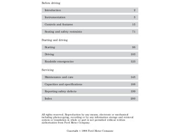
Make sure the corresponding lights illuminate briefly. If a light fails to illuminate, have the vehicle serviced. † If the driver’s safety belt is fastened, the STARTING THE ENGINE 1. Turn the key to 5 (START) without pressing the accelerator pedal and release as soon as the engine starts. The key will return to 4 (ON).
light will not illuminate.
2. If the temperature is above –12°C (10°F) and the engine does not start within five seconds on the first try, turn the key to OFF, wait ten seconds and try again. 3. If the temperature is below –12°C (10°F) and the engine does not start in fifteen seconds on the first try, turn the key OFF and wait ten seconds and try again. If the engine does not start in two attempts, depress the accelerator and start the engine while holding the accelerator down to the floor. Release the accelerator when the engine starts. 4. After idling for a few seconds, apply the brake and release the parking brake.
100
Starting
Using the engine block heater (if equipped) An engine block heater warms the engine coolant, which improves starting, warms up the engine faster and allows the heater-defroster system to respond quickly. Use of an engine block heater is strongly recommended if you live in a region where temperatures reach –23°C (–10°F) or below. For best results, plug the heater in at least three hours before starting the vehicle. Using the heater for longer than three hours will not harm the engine, so the heater can be plugged in the night before starting the vehicle.
To prevent electrical shock, do not use your heater with ungrounded electrical systems or two-pronged (cheater)
adapters.
Guarding against exhaust fumes Although odorless and colorless, carbon monoxide is present in exhaust fumes. Take precautions to avoid its dangerous effects.
If you ever smell exhaust fumes of any kind inside your vehicle, have your dealer inspect and fix your vehicle immediately. Do not drive if you smell exhaust fumes. These fumes are harmful and could kill you.
Have the exhaust and body ventilation systems checked whenever: † the vehicle is raised for service. † the sound of the exhaust system changes. † the vehicle has been damaged in a collision.
Engine exhaust, some of its constituents, and certain vehicle components contain or emit chemicals known to the State of California to cause cancer, and birth defects or other reproductive harm.
101
Starting
Important ventilating information If the engine is idling while the vehicle is stopped in an open area for long periods of time, open the windows at least 2.5 cm (one inch). Adjust the heating or air conditioning (if equipped) to bring in fresh air. Improve vehicle ventilation by keeping all air inlet vents clear of snow, leaves and other debris.
102
Driving
BRAKES Your service brakes are self-adjusting. Refer to the “Service Guide” for scheduled maintenance. Occasional brake noise is normal and often does not indicate a performance concern with the vehicle’s brake system. In normal operation, automotive brake systems may emit occasional or intermittent squeal or groan noises when the brakes are applied. Such noises are usually heard during the first few brake applications in the morning; however, they may be heard at any time while braking and can be aggravated by environmental conditions such as cold, heat, moisture, road dust, salt or mud. If a “metal-to-metal,” “continuous grinding” or “continuous squeal” sound is present while braking, the brake linings may be worn-out and should be inspected by a qualified service technician.
Four-wheel anti-lock brake system (ABS) (if equipped) On vehicles equipped with an anti-lock braking system (ABS), a noise from the hydraulic pump motor and pulsation in the pedal may be observed during ABS braking events. Pedal pulsation coupled with noise while braking under panic conditions or on loose gravel, bumps, wet or snowy roads is normal and indicates proper functioning of the vehicle’s anti-lock brake system. If the vehicle has continuous vibration or shudder in the steering wheel while braking, the vehicle should be inspected by a qualified service technician. The ABS operates by detecting the onset of wheel lockup during brake applications and compensating for this tendency. The wheels are prevented from locking even when the brakes are firmly applied. The accompanying illustration depicts the advantage of an ABS equipped vehicle (on bottom) to a non-ABS equipped vehicle (on top) during hard braking with loss of front braking traction.
103
Driving
ABSwarninglamp The ABS warning lamp in the instrument cluster momentarily illuminates when the ignition is turned on and the engine is off. If the light does not illuminate momentarily at start up, remains on or continues to flash, the ABS needs to be serviced. With the ABS light on, the anti-lock brake system is disabled and normal braking is still effective unless the brake warning light also remains illuminated with parking brake released. (If your brake warning lamp illuminates, have your vehicle serviced immediately). UsingABS † In an emergency or when maximum efficiency from the ABS is
BRAKE
required, apply continuous full force on the brake. The ABS will be activated immediately, thus allowing you to retain full steering control of your vehicle and, providing there is sufficient space, will enable you to avoid obstacles and bring the vehicle to a controlled stop. † The Anti-Lock system does not decrease the time necessary to apply the brakes or always reduce stopping distance. Always leave enough room between your vehicle and the vehicle in front of you to stop.
† We recommend that you familiarize yourself with this braking
technique. However, avoid taking any unnecessary risks.
Rear anti-lock brake system (RABS) (if equipped) Rear Anti-lock Brake System (RABS) is designed to help you maintain directional stability in emergency stopping situations. With RABS, the rear brakes are kept from locking during panic stops; however, the front wheels can lock because they are not controlled by RABS. A clicking noise and slight pedal pulsation during RABS braking events indicates the RABS is functioning. Pedal pulsation coupled with clicking noise while braking under panic conditions on loose gravel, wet or snowy roads is normal and indicates proper functioning of the vehicle’s RABS. If the vehicle has continuous vibration or shudder in the steering wheel while braking, the vehicle should be inspected by a qualified service technician. The RABS operates by detecting the onset of rear wheel lockup during brake applications and compensating for this tendency.
104
Driving
RABSwarninglamp The ABS warning lamp in the instrument cluster illuminates if a RABS fault is detected. Have your vehicle serviced as soon as possible. Normal braking is still effective unless the BRAKE warning lamp is also illuminated.
BRAKE
UsingRABS † In an emergency, applying full pressure may cause the front wheels to lock. If the front brakes lock, the vehicle cannot be steered. You should apply the brakes with steadily increasing force, as if “squeezing” the brakes. If you feel the front wheels begin to lock, momentarily release the pedal and repeat the “squeeze” technique. † We recommend that you familiarize yourself with how the RABS
performs. However, avoid unnecessary risks.
Parking brake The operation of the Type A and Type B parking brakes are basically the same except where noted. †Type A
PUSH
ON
PUSH OFF
HOOD
105
Driving †Type B Apply the parking brake whenever the vehicle is parked. Push pedal downward to set the parking brake.
The BRAKE warning lamp in the instrument cluster illuminates and remains illuminated (when the ignition is turned ON) until the parking brake is released.
BRAKE
Always set the parking brake fully and make sure the gearshift is latched in P (Park). Turn off the ignition whenever you leave
your vehicle.
The parking brake is not recommended to stop a moving vehicle. However, if the normal brakes fail, the parking brake can be used to stop your vehicle in an emergency. Since the parking brake applies only the rear brakes, the vehicle’s stopping distance will increase greatly and the handling of your vehicle will be adversely affected. †Type A Push the pedal downward again to release the parking brake. Driving with the parking brake on will cause the brakes to wear out quickly and reduce fuel economy.
PUSH OFF
PUSH
ON
HOOD
106
Driving
†Type B Pull the release lever to release the parking brake. Driving with the parking brake on will cause the brakes to wear out quickly and reduce fuel economy.
for more than a few seconds when the engine is running.
STEERING Your vehicle is equipped with power steering. Power steering uses energy from the engine to help steer the vehicle. To prevent damage to the power steering pump: † Never hold the steering wheel to the extreme right or the extreme left † Do not operate the vehicle with a low power steering pump fluid level. If the power steering system breaks down (or if the engine is turned off), you can steer the vehicle manually, but it takes more effort. If the steering wanders or pulls, the condition could be caused by any of the following: † underinflated tire(s) on any wheel(s) † high crown in center of road † high crosswinds † wheels out of alignment † loose or worn components in steering linkage
107
Driving
TRACTION-LOK AXLE (IF EQUIPPED) This axle provides added traction on slippery surfaces, particularly when one wheel is on a poor traction surface. Under normal conditions, the Traction-Lok axle functions like a standard rear axle. Extended use of other than the manufacturer’s specified size tires on a Traction-Lok rear axle could result in a permanent reduction in effectiveness. This loss of effectiveness does not affect normal driving and should not be noticeable to the driver.
To avoid injury, never run the engine with one wheel off the ground, such as when changing a tire.
TRANSMISSION OPERATION
Brake-shift interlock This vehicle is equipped with a brake-shift interlock feature that prevents the gearshift from being moved from P (Park) unless the brake pedal is depressed. If you cannot move the gearshift out of P (Park) with the brake pedal depressed: 1. Apply the parking brake, turn ignition key to LOCK, then remove the key. 2. Insert the key and turn it to OFF. Apply the brake pedal and shift to N (Neutral). 3. Start the vehicle. If it is necessary to use the above procedure to move the gearshift, it is possible that a fuse has blown or the vehicle’s brakelamps are not operating properly. Refer to Fuses and relays in the Roadside emergencies chapter.
Do not drive your vehicle until you verify that the brakelamps are working.
If your vehicle gets stuck in mud or snow it may be rocked out by shifting from forward and reverse gears, stopping between shifts, in a steady pattern. Press lightly on the accelerator in each gear.
108
Driving
Do not rock the vehicle for more than a few minutes. The transmission and tires may be damaged or the engine may overheat.
Always set the parking brake fully and make sure the gearshift is latched in P (Park). Turn off the ignition whenever you leave
your vehicle.
If the parking brake is fully released, but the brake warning lamp remains illuminated, the brakes may not be working properly.
See your dealer or a qualified service technician.
Driving with a 4–speed automatic transmission Understandinggearshiftpositions Pull the gearshift lever towards you and downward to move the automatic gearshift.
Hold the brake pedal down while you move the gearshift lever from P (Park) to another position. If you do not hold the brake pedal down, your vehicle may move unexpectedly and injure someone.
P(Park) Always come to a complete stop before shifting into P (Park). Make sure the gearshift is securely latched in P (Park). This position locks the transmission and prevents the rear wheels from turning.
Always set the parking brake fully and make sure the gearshift is securely latched in P (Park).
Never leave your vehicle unattended while it is running.
109
Driving
R(Reverse) With the gearshift in R (Reverse), the vehicle will move backward. Always come to a complete stop before shifting into and out of R (Reverse). N(Neutral) With the gearshift in N (Neutral), the vehicle can be started and is free to roll. Hold the brake pedal down while in this gear.
(Overdrive)
The normal driving position for the best fuel economy. Transmission operates in gears one through four.
(Overdrive) can be deactivated
by pressing the Transmission Control Switch (TCS) on the end of the gearshift lever. The transmission control indicator light (TCIL) (the word OFF) on the end of the gearshift lever will illuminate.
OVERDRIVE OFF
OVERDRIVE
Drive – Not shown on the display. Activate by pressing the Transmission Control Switch (TCS) on the end of the gearshift lever with the gearshift in the gearshift lever. Transmission operates in gears one through three.
position. The TCIL (the word OFF) will illuminate on the
(Drive) provides more engine braking than
(Overdrive) and is
useful when: † driving with a heavy load. † towing a trailer up or down steep hills. † additional engine downhill braking is desired. If towing a trailer, refer
to Driving while you tow in the Trailer towing section.
To return to Switch (TCS). The TCIL (the word OFF) will no longer be illuminated.
(Overdrive) mode, press the Transmission Control
110
Driving
Each time the vehicle is started, the transmission will automatically return to normal overdrive mode. Every time the vehicle is shut off and restarted, you must press the transmission control switch to cancel overdrive operation if driving in overdrive is not desired. 2(Second) Use 2 (Second) to start-up on slippery roads or to provide additional engine braking on downgrades.
1(First) Use 1 (Low) to provide maximum engine braking on steep downgrades. Upshifts can be made by shifting to 2 (Second) or to
(Overdrive). Selecting 1 (Low)
at higher speeds causes the transmission to shift to a lower gear, and will shift to 1 (Low) after vehicle decelerates to the proper speed.
VEHICLE LOADING Before loading a vehicle, familiarize yourself with the following terms: † Base Curb Weight : Weight of the vehicle including any standard equipment, fluids, lubricants, etc. It does not include passengers or aftermarket equipment. † Payload : Combined maximum allowable weight of cargo, passengers and optional equipment. The payload equals the gross vehicle weight rating minus base curb weight.
† GVW (Gross Vehicle Weight) : Base curb weight plus payload † GVWR (Gross Vehicle Weight Rating) : Maximum total weight of
weight. The GVW is not a limit or a specification.
the base vehicle, passengers, optional equipment and cargo. The GVWR is specific to each vehicle and is listed on the Safety Compliance Label on the driver’s door pillar.
† GAWR (Gross Axle Weight Rating) : Carrying capacity for each
axle system. The GAWR is specific to each vehicle and is listed on the Safety Compliance Label on the driver’s door pillar.
111
Driving † GCWR (Gross Combined Weight Rating) : Maximum combined weight of towing vehicle (including passengers and cargo) and the trailer. The GCWR indicates the maximum loaded weight that the vehicle is designed to tow.
† Maximum Trailer Weight Rating : Maximum weight of a trailer the
vehicle is permitted to tow. The maximum trailer weight rating is determined by subtracting the vehicle curb weight for each engine/transmission combination, any required option weight for trailer towing and the weight of the driver from the GCWR for the towing vehicle. † Maximum Trailer Weight : maximum weight of a trailer the loaded
vehicle (including passengers and cargo) is permitted to tow. It is determined by subtracting the weight of the loaded trailer towing vehicle from the GCWR for the towing vehicle.
† Trailer Weight Range : Specified weight range that the trailer must fall within that ranges from zero to the maximum trailer weight rating.
Remember to figure in the tongue load of your loaded trailer when figuring the total weight.
Do not exceed the GVWR or the GAWR specified on the Safety Compliance Certification Label.
Do not use replacement tires with lower load carrying capacities than the originals because they may lower the vehicle’s GVWR and GAWR limitations. Replacement tires with a higher limit than the originals do not increase the GVWR and GAWR limitations. The Certification Label, found on the inside pillar of the driver’s door, lists several important vehicle weight rating limitations. Before adding any additional equipment, refer to these limitations. If you are adding weight to the front of your vehicle, (potentially including weight added to the cab), the weight added should not exceed the Front Axle Reserve Capacity (FARC). Additional frontal weight may be added to the front axle reserve capacity provided you limit your payload in other ways (i.e. restrict the number of passengers or amount of cargo carried). You may add equipment throughout your vehicle if the total weight added is equal to or less than the Total Axle Reserve Capacity (TARC) weight. You should NEVER exceed the Total Axle Reserve Capacity. Always ensure that the weight of passengers, cargo and equipment being carried is within the weight limitations that have been established for
112
Driving
your vehicle including both Gross Vehicle Weight and Front and Rear Gross Axle Weight Rating limits. Under no circumstance should these limitations be exceeded. Exceeding any vehicle weight rating limitation could result in serious damage to the vehicle and/or personal injury.
Calculating the load your vehicle can carry/tow 1. Use the appropriate maximum gross combined weight rating (GCWR) chart to find the maximum GCWR for your type engine and rear axle ratio. 2. Weigh your vehicle as you customarily operate the vehicle without cargo. To obtain correct weights, try taking your vehicle to a shipping company or an inspection station for trucks. 3. Subtract your loaded vehicle weight from the maximum GCWR on the following charts. This is the maximum trailer weight your vehicle can tow and must fall below the maximum shown under maximum trailer weight on the chart.
DRIVING THROUGH WATER Do not drive quickly through standing water, especially if the depth is unknown. Traction or brake capability may be limited and if the ignition system gets wet, your engine may stall. Water may also enter your engine’s air intake and severely damage your engine. If driving through deep or standing water is unavoidable, proceed very slowly. Never drive through water that is higher than the bottom of the hubs. Once through the water, always try the brakes. Wet brakes do not stop the vehicle as effectively as dry brakes. Drying can be improved by moving your vehicle slowly while applying light pressure on the brake pedal. Driving through deep water where the transmission is submerged may allow water into the transmission and cause internal transmission damage.
TRAILER TOWING Refer to 7.3 Liter Power Stroke Direct Injection Turbo Diesel Owner’s Guide Supplement for diesel engine towing information. Your vehicle may tow a class I, II or III trailer provided the maximum trailer weight is less than or equal to the maximum trailer weight listed for your engine and rear axle ratio on the following charts.
113
Driving
Trailer Towing Table
GCWR (Gross Combined Weight Rating)/Trailer Weights
Engine
Rear axle ratio
Maximum GCWR-kg
(lbs.)
Trailer weight
Maximum
range-kg
(lbs.)
(0-Maximum)
Frontal Area Of Trailer-m2
(ft2)
4.2L
4.6L
5.4L
4.2L
5.4L
4.2L
5.4L
4.2L
5.4L
3.55
3.55
3.55
3.73
3.73
4.09
3.73
3.73
3.73
2 313 (5 100)
5.52 (60)
2 993 (6 600)
5.52 (60)
Regular Van E-150
4 536(10 000)
5 216
(11 500)
5 443
3 130 (6 900)
(12 000) Regular Van E-250
4 7632 359 (5 200)
(10 500)
5 897
3 402 (7 500)
(13 000) Regular Van E-250 HD
5.52 (60)
5.52 (60)
5.52 (60)
4 990
(11 000)
5 897
(13 000)
2 586 (5 700)
5.52 (60)
3 402 (7 500)
5.52 (60)
Super Van E-250
4 7632 313 (5 100)
(10 500)
5 897
3 357 (7 400)
(13 000) Super Van E-250 HD
5.52 (60)
5.52 (60)
(3 901 kg [8 600 lb.]-3 924 kg [8 650 lb.] GVW)
(3 901 kg [8 600 lb.]-3 924 kg [8 650 lb.] GVW)
4.2L
4.09
4 990
(11 000)
2 540 (5 600)
5.52 (60)
114
GCWR (Gross Combined Weight Rating)/Trailer Weights
Trailer Towing Table
Driving
Maximum GCWR-kg
(lbs.)
5 897
Trailer weight
Maximum
range-kg
(lbs.)
(0-Maximum)
Frontal Area Of Trailer-m2
(ft2)
3 356 (7 400)
(13 000) Regular Van E-350
5 4432 948 (6 500)
5.52 (60)
5.52 (60)
3 402 (7 500)
5.52 (60)
4 218 (9 300)
5.52 (60)
4 536 (10 000)
5.52 (60)
4 536 (10 000)
5.52 (60)
4 536 (10 000)
5.52 (60)
Super Van E-350
5 4432 858 (6 300)
5.52 (60)
Engine
Rear axle ratio
5.4L
3.73
5.4L
5.4L
6.8L
6.8L
7.3L
(Diesel)
7.3L
(Diesel)
5.4L
5.4L
6.8L
6.8L
7.3L
(Diesel)
7.3L
(Diesel)
3.55
4.10
3.73
4.10
3.55
4.10
3.55
4.10
3.73
4.10
3.55
4.10
(12 000)
5 897
(13 000)
6 804
(15 000)
8 392
(18 500)
7 258
(16 000)
9 072
(20 000)
(12 000)
5 897
(13 000)
6 804
(15 000)
8 392
(18 500)
7 258
(16 000)
9 072
(20 000)
3 311 (7 300)
5.52 (60)
4 173 (9 200)
5.52 (60)
4 536 (10 000)
5.52 (60)
4 445 (9 800)
5.52 (60)
4 536 (10 000)
5.52 (60)
115
Driving
GCWR (Gross Combined Weight Rating)/Trailer Weights
Trailer Towing Table
Trailer weight
Maximum
Rear axle ratio
Maximum GCWR-kg
(lbs.)
range-kg
(lbs.)
(0-Maximum) Club Wagon E-150 (8 passenger)
Frontal Area Of Trailer-m2
(ft2)
3.55
3.55
3.55
4 536
(10 000)
5 216
(11 500)
5 443
(12 000)
2 132 (4 700)
5.52 (60)
2 767 (6 100)
5.52 (60)
2 948 (6 500)
5.52 (60)
Club Wagon Regular E-350 (12 passenger)
3.55
4.10
3.73
4.10
3.55
4.10
5 443
(12 000)
5 897
(13 000)
6 804
(15 000)
8 392
(18 500)
7 258
(16 000)
9 072
(20 000)
2 722 (6 000)
5.52 (60)
3 175 (7 000)
5.52 (60)
4 037 (8 900)
5.52 (60)
4 536 (10 000)
5.52 (60)
4 309 (9 500)
5.52 (60)
4 536 (10 000)
5.52 (60)
Club Wagon Super E-350 (15 passenger)
3.55
4.10
3.73
5 443
(12 000)
5 897
(13 000)
6 804
(15 000)
2 586 (5 700)
5.52 (60)
3 039 (6 700)
5.52 (60)
3 901 (8 600)
5.52 (60)
Engine
4.2L
4.6L
5.4L
5.4L
5.4L
6.8L
6.8L
7.3L
(Diesel)
7.3L
(Diesel)
5.4L
5.4L
6.8L
116
GCWR (Gross Combined Weight Rating)/Trailer Weights
Trailer Towing Table
Driving
Engine
6.8L
7.3L
(Diesel)
7.3L
Rear axle ratio
4.10
3.55
Maximum GCWR-kg
(lbs.)
8 392
(18 500)
7 258
(16 000)
9 072
Trailer weight
Maximum
range-kg
(lbs.)
(0-Maximum)
Frontal Area Of Trailer-m2
(ft2)
4 536 (10 000)
5.52 (60)
4 173 (9 200)
5.52 (60)
(Diesel) E-350 RV Cutaway (single rear wheel-4 355 kg [9 600 lb] GVW)
(20 000)
4 536 (10 000)
5.52 (60)
4.10
7.3L
(Diesel)
4.10
9 072
(20 000)
4 717
(10 400)*
5.52 (60)
E-350 RV Cutaway (dual rear wheel)
5.4L
6.8L
7.3L
(Diesel)
7.3L
(Diesel)
5.4L
6.8L
7.3L
(Diesel)
4.10
4.10
4.10
5 897
(13 000)
8 392
(18 500)
9 072
(20 000)
1 134 (2 500)
5.52 (60)
3 629 (8 000)
5.52 (60)
4 309 (9 500)
5.52 (60)
E-350 Commercial Cutaway (single rear wheel)
4.10
9 072
(20 000)
4 717 (10
400)*
5.52 (60)
E-350 Commercial Cutaway (dual rear wheel)
4.10
4.10
4.10
5 897
(13 000)
8 392
(18 500)
9 072
(20 000)
1 225 (2 700)
5.52 (60)
3 720 (8 200)
5.52 (60)
4 400 (9 700)
5.52 (60)
117
Driving
GCWR (Gross Combined Weight Rating)/Trailer Weights
Trailer Towing Table
(Diesel) E-250/350 Stripped Chassis (single rear wheel-124(wheelbase
(20 000)
4 536 (10 000)
5.52 (60)
4.10
Maximum GCWR-kg
(lbs.)
Trailer weight
Maximum
range-kg
(lbs.)
(0-Maximum)
Frontal Area Of Trailer-m2
(ft2)
E-Super Duty
4 536 (10 000)
5.52 (60)
9 072
(20 000)
9 072
(11 000)
5 897
(13 000)
6 804
(15 000)
for E-250 only) 4 990
1 090 (2 400)
5.52 (60)
1 542 (3 400)
5.52 (60)
2 540 (5 600)
5.52 (60)
Rear axle ratio
4.63
4.09
4.10
3.73
Engine
6.8L
7.3L
4.2L
5.4L
6.8L
5.4L
6.8L
E-350 Stripped Chassis (dual rear wheel)
4.10
4.10
5 897
(13 000)
8 392
(18 500)
1 361 (3 000)
5.52 (60)
3 856 (8 500)
5.52 (60)
Maximum loaded trailer weight of 4 717 kg (10 400 lbs.) on 7.3L E350
RV and commercial cutaways (single rear wheel) applicable to fifth wheel trailer usage only. Otherwise, maximum trailer weight is 4 536 kg (10 000 lbs.). For high altitude operation reduce GCWR by 2% per 300 meters (1 000 ft) elevation. To determine the maximum trailer weight designed for you particular vehicle as equipped, follow the section Calculating the load your vehicle can tow/carry earlier in this chapter.118
Driving
Your vehicle’s load capacity is designated by weight, not by volume, so you cannot necessarily use all available space when loading a vehicle. Distribute the load so that only 10 to 15% of the total is on the tongue. Tie down the load so that it does not shift and change the weight on the hitch. Towing a trailer places an additional load on your vehicle’s engine, transmission, axle, brakes, tires and suspension. Inspect these components carefully after any towing operation.
Do not exceed the GVWR or the GAWR specified on the Safety Compliance Certification Label.
Towing trailers beyond the maximum recommended gross trailer weight could result in engine damage, transmission/axle damage,
structural damage, loss of control, and personal injury.
Preparing to tow Use the proper equipment for towing a trailer, and make sure it is properly attached to your vehicle. See your dealer or a reliable trailer dealer if you require assistance. Hitches Do not use or install hitches that clamp onto the bumper or to the axle. Underbody hitches are acceptable if installed properly. Safetychains Always connect the trailer’s safety chains to the vehicle. To connect the trailer’s safety chains, cross the chains under the trailer tongue and allow slack for turning corners. If you use a rental trailer, follow the instructions that the rental agency gives to you. Do not attach safety chains to the bumper.
119
Driving
Trailerbrakes Electric brakes and manual, automatic or surge-type brakes are safe if installed properly and adjusted to the manufacturer’s specifications. The trailer brakes must meet local and Federal regulations.
Do not connect a trailer’s hydraulic brake system directly to your vehicle’s brake system. Your vehicle may not have enough
braking power and your chances of having a collision greatly increase.
The braking system of the tow vehicle is rated for operation at the GVWR not GCWR. Trailerlamps Trailer lamps are required on most towed vehicles. Make sure your trailer lamps conform to local and Federal regulations. See your dealer or trailer rental agency for proper instructions and equipment for hooking up trailer lamps. Usingastepbumper The rear bumper is equipped with an integral hitch and requires only a ball with a 25.4 mm (one inch) shank diameter. The bumper has a 2 270 kg (5 000 lb.) trailer weight and 227 kg (500 lb.) tongue weight capability. If it is necessary to relocate the trailer hitch ball position, a frame-mounted trailer hitch must be installed.
Driving while you tow Do not drive faster than 88 km/h (55 mph) when towing a trailer. Do not drive faster than 72 km/h (45 mph) with any weight on the trailer while towing on a hot day or in hilly country. Speed control may shut off if you are towing on long, steep grades. When towing a trailer: † Use D (Drive) or a lower gear when towing up or down steep hills.
This will eliminate excessive downshifting and upshifting for optimum fuel economy and transmission cooling.
† Anticipate stops and brake gradually. When descending long, steep downhill grades, always use a lower gear to provide engine braking to save wear on brakes. Use Drive (Overdrive
120
Driving
OFF) on moderately steep hills, Second (2) on steep hills, and First (1) on very steep hills. Servicingaftertowing If you tow a trailer for long distances, your vehicle will require more frequent service intervals. Refer to your maintenance guide and or service guide for more information.
Trailer towing tips † Practice turning, stopping and backing up in an area before starting on a trip to get the feel of the vehicle trailer combination. When turning, make wider turns so the trailer wheels will clear curbs and other obstacles.
† Allow more distance for stopping with a trailer attached. † The trailer tongue weight should be 10–15% of the loaded trailer † If you will be towing a trailer frequently in hot weather, hilly conditions, at GCW, or any combination of these factors, consider refilling your rear axle with synthetic gear lube. Refer to the Capacities and specifications chapter for the lubricant specification.
† After you have traveled 80 km (50 miles), thoroughly check your † When stopped in traffic for long periods of time in hot weather, place
hitch, electrical connections and trailer wheel lug nuts.
weight.
the gearshift in P (Park) and increase idle speed. This aids engine cooling and air conditioner efficiency. † Vehicles with trailers should not be parked on a grade. If you must
park on a grade, place wheel chocks under the trailer’s wheels.
Launching or retrieving a boat When backing down a ramp during boat launching or retrieval, † Do not allow the static water level to rise above the bottom edge of † Do not allow waves to break higher than 15 cm (six inches) above the
the rear bumper and
bottom edge of the rear bumper.
Exceeding these limits may allow water to enter critical vehicle components, adversely affecting driveability, emissions, reliability and causing internal transmission damage.
121
Driving
Replace the rear axle lubricant anytime the axle has been submerged in water. Rear axle lubricant quantities are not to be checked or changed unless a leak is suspected or repair required. Disconnect the wiring to the trailer before backing the trailer into the water. Reconnect the wiring to the trailer after the trailer is removed from the water.
122
Roadside emergencies
HAZARD LIGHTS CONTROL Use only in an emergency to warn traffic of vehicle breakdown, approaching danger, etc. The hazard flashers can be operated when the ignition is off. † The hazard lights control is
located on top of the steering column.
† Depress hazard lights control to
activate all hazard flashers simultaneously.
† Depress control again to turn the
flashers off.
FUEL PUMP SHUT-OFF SWITCH After a collision, if the engine cranks but does not start, the fuel pump shut-off switch may have been activated. The shut-off switch is a device intended to stop the electric fuel pump when your vehicle has been involved in a substantial jolt. 1. Turn the ignition to the OFF position. 2. Check the fuel system for leaks. 3. If no fuel leak is apparent, reset the fuel pump shut-off switch by pushing in the reset button. 4. Turn the ignition to the ON position. Pause for a few seconds and return the key to the OFF position. 5. Make a further check for leaks in the fuel system.
123
Roadside emergencies
The fuel pump shut-off switch is located in the passenger’s foot well, behind the kick panel, except for commercial stripped chassis vehicles.
124
Roadside emergencies
For commercial stripped chassis vehicles, the fuel pump shut-off switch is located on a bracket above the brake pedal.
FUSES AND RELAYS
Fuses If electrical components in the vehicle are not working, a fuse may have blown. Blown fuses are identified by a broken wire within the fuse. Check the appropriate fuses before replacing any electrical components.
15
15
Always replace a fuse with one that has the specified amperage rating. Using a fuse with a higher amperage rating can cause
severe wire damage and could start a fire.
125
Roadside emergencies
Standardfuseamperageratingandcolor
Fuse Rating
2A 3A 4A 5A 7.5A 10A 15A 20A 25A 30A 40A 50A 60A 70A 80A
Mini Fuses
Grey Violet Pink Tan
Brown
Red Blue Yellow Natural Green
— — — — —
COLOR
Standard
Fuses
Maxi Fuses
Grey Violet Pink Tan
Brown
Red Blue Yellow Natural Green
— — — — —
— — — — — — —
Yellow
—
Green Orange
Red Blue Tan
Natural
Cartrigde
Maxi Fuses
— — — — — — — Blue — Pink Green Red — — —
Fuse Link Cartridge
— — — — — — — Blue — Pink
Orange
Red Yellow Brown Black
Passenger compartment fuse panel The fuse panel is located below and to the left of the steering wheel by the brake pedal. Remove the panel cover to access the fuses. To remove a fuse use the fuse puller tool provided on the fuse panel cover.
126
Roadside emergencies
13
19
25
31
37
14
20
26
32
38
15
21
27
33
39
10
16
22
28
34
40
11
17
23
29
35
41
42
43
44
12
18
24
30
36
The fuses are coded as follows. Fuse/Relay Location
Fuse Amp
Rating
Description
20A 15A
15A 15A
20A
10A 10A
RABS/4WABS Module Brake Warning Diode/Resistor, Instrument Cluster, Warning Chime, 4WABS Relay, Warning Indicators Main Light Switch, RKE Module, Radio Power Locks w/RKE, Illuminated Entry, Warning Chime, Modified Vehicle, Power Mirrors, Main Light Switch, Courtesy Lamps RKE Module, Power Lock Switches, Memory Lock, Power Locks with RKE Shift Interlock, Speed Control, DRL Module Multi-Function Switch, Turn Signals
127
Roadside emergencies
Fuse/Relay Location
Fuse Amp
Rating
Description
30A
30A
20A
15A
15A
15A
5A
5A 30A — — 10A 5A 30A 15A 20A 5A 10A — 5A 25A — 15A
Radio Capacitor(s), Ignition Coil, PCM Diode, PCM Power Relay, Fuel Heater, Glow Plug Relay (Diesel Only) Wiper Control Module, Windshield Wiper Motor Main Light Switch, (External Lamps) Multi-Function Switch (Flash-to-pass) Brake Pressure Switch, Multi-Function Switch (Hazards), RABS, Brake Pedal Position Switch Transmission Range (TR) Sensor, Auxiliary Battery Relay Blend Door Actuator, Function Selector Switch Instrument Cluster (Air Bag and Charge Indicator) Trailer Battery Charge Relay Power Seats Not Used Not Used Air Bag Diagnostic Monitor Overdrive Cancel Switch Power Windows* Memory Power Radio Cigar Lighter, Data Link Connector (DLC) Illuminated Entry Module Left Headlamp (Low Beam) Not Used Radio Power Plug Not Used Headlamps (High Beam Indicator), DRL10A
10
11
12
13
14
15
16
17
18
19
20
21
22
23
24
25
26
27
28
29
30128
Roadside emergencies
Fuse/Relay Location
Fuse Amp
Rating
Description
31
32
33
34
35
3637
38
39
40
41
42
43
4410A — — 10A — 5A
— 10A — 30A 30A —
20A C.B.
—
Right Headlamp (Low Beam), DRL Not Used Not Used Transmission Range (TR) Sensor Not Used (Cluster, A/C, Illumination, Radio), Steering Column Assembly Not Used Air Bag Diagnostic Monitor Not Used Modified Vehicle Modified Vehicle Not Used Power Windows* Not Used
* Either fuse 21 or circuit breaker 43 will be present for power windows.
Power distribution box The power distribution box is located in the engine compartment. The power distribution box contains high-current fuses that protect your vehicle’s main electrical systems from overloads.
Always disconnect the battery before servicing high current fuses.
Always replace the cover to the Power Distribution Box before reconnecting the battery or refilling fluid reservoirs.
129
Roadside emergencies
32
The high-current fuses are coded as follows. Fuse/Relay Location
Fuse Amp
Rating
Description
10
11
12
13130
— — — 10A
10A 10A — 60A 30A
60A
30A 60A 50A
Not Used Not Used Not Used PCM Keep Alive Memory, Instrument Cluster Right Trailer Turn Signal Left Trailer Turn Signal Not Used I/P Fuses 5, 11, 23, 38, 4, 10, 16, 22, 28
PCM Power Relay, Engine Compartment Fuse 4
Auxiliary Battery Relay, Engine Compartment Fuses 14, 22
IDM Relay Engine Compartment Fuses 26, 27
Blower Motor Relay (Blower Motor)Roadside emergencies
Fuse/Relay Location
Fuse Amp
Rating
Description
14
15
16
17
18
19
20
21
2223
24
25
26
27
28
2930A
40A 50A 30A 60A 60A 20A 50A 40A
60A — 20A 10A 15A — — — — — — — — — — — —
Trailer Running Lamps Relay, Trailer Backup Lamps Relay Main Light Switch RKE Module, Auxiliary Blower Motor Relay Fuel Pump Relay, IDM (Diesel) I/P Fuses 40, 41
4WABS Module Electric Brake Controller Modified Vehicle Power Trailer Battery Charge Relay (Modified Vehicles Only) Ignition Switch Not Used NGV Module Generator/Voltage Regulator (Diesel Only) DRL Module, Horn Relay PCM Diode Not Used Not Used Not Used Trailer Backup Lamps Relay Trailer Running Lamps Relay Trailer Running Lamps Relay IDM Relay PCM Relay Blower Motor Relay Horn Relay Fuel Pump Relay, IDM Relay (Diesel)Relays Relays are located in the power distribution box and should be replaced by qualified technicians.
131
Roadside emergencies
CHANGING THE TIRES If you get a flat tire while driving, do not apply the brake heavily. Instead, gradually decrease your speed. Hold the steering wheel firmly and slowly move to a safe place on the side of the road.
Spare tire information The spare tire for your vehicle is stowed under the rear of your vehicle (except cutaway and stripped chassis models). Toremovethesparetire: 1. Open both rear doors and remove thumb screw and anti-theft bracket. If finger pressure will not remove the thumb screw, use the lug wrench to loosen the screw. 2. Remove the access cover from the rubber strip behind the left door.
3. Remove the lug wrench from the right side compartment and insert the tapered end of the lug wrench or the tip of the jack handle through the access hole and into the tube. 4. Turn the wrench counterclockwise until the cable is slack and the tire can be slid rearward from under the vehicle. 5. Remove the retainer from the spare tire. To stow the cable retainer with the spare removed, turn the jack handle wrench clockwise until all slack is removed. Tostowthesparetire: 1. Lay the tire on the ground under the rear of the vehicle with the valve stem facing up. Stow aluminum wheels with valve stem facing down. 2. Install the retainer through the wheel center.
132
Roadside emergencies
3. Raise the tire by turning the wrench or handle clockwise. Continue until the lift mechanism “clicks.” 4. Check that the tire is tightly seated under the vehicle by pushing against the tire. Retighten as necessary. 5. Replace the access cover, anti-theft bracket and thumb screw. Use finger pressure only to secure the thumb screw.
Make sure the spare tire and jacking equipment are stowed and secured in the proper storage location.