- Download PDF Manual
-
Do not put anything on or over the air bag module. Placing objects on or over the air bag inflation area may cause those
objects to be propelled by the air bag into your face and torso causing serious injury.
109
2006 F-250/350/450/550 (f23) Owners Guide (post-2002-fmt) USA (fus)
Seating and Safety Restraints
Do not attempt to service, repair, or modify the airbag supplemental restraint systems or its fuses. See your authorized
dealer.
The front passenger air bag is not designed to offer protection to an occupant in the center front seating position.
Modifying or adding equipment to the front end of the vehicle (including frame, bumper, front end body structure and tow
hooks) may affect the performance of the airbag system, increasing the risk of injury. Do not modify the front end of the vehicle.
Additional equipment such as snowplow equipment may effect the performance of the airbag sensors increasing the risk of
injury. Please refer to the Body Builders Layout Book for instructions about the appropriate installation of additional equipment.
Removing the blocker beam without installing snow plow attachment hardware may effect airbag deployment in a crash.
Do not operate the truck unless either the blocker beam or snow plow attachment hardware is installed on the vehicle.
Children and airbags For additional important safety information, read all information on safety restraints in this guide. Children must always be properly restrained. Failure to follow these instructions may increase the risk of injury in a collision.
An infant in a rear-facing seat faces a high risk of serious or fatal injuries from a deploying passenger airbag. Rear facing infant
seats should NEVER be placed in the front seats, unless the passenger airbag is turned off. See Passenger airbag ON/OFF switch.
110
2006 F-250/350/450/550 (f23) Owners Guide (post-2002-fmt) USA (fus)
Seating and Safety Restraints
How does the airbag supplemental restraint system work? The airbag SRS is designed to activate when the vehicle sustains sufficient longitudinal deceleration. The fact that the airbags did not inflate in a collision does not mean that something is wrong with the system. Rather, it means the forces were not of the type sufficient to cause activation. Airbags are designed to inflate in frontal and near-frontal collisions, not rollover, side-impact, or rear-impacts. The airbags inflate and deflate rapidly upon activation. After airbag deployment, it is normal to notice a smoke-like, powdery residue or smell the burnt propellant. This may consist of cornstarch, talcum powder (to lubricate the bag) or sodium compounds (e.g., baking soda) that result from the combustion process that inflates the airbag. Small amounts of sodium hydroxide may be present which may irritate the skin and eyes, but none of the residue is toxic. While the system is designed to help reduce serious injuries, it may also cause minor abrasions, swelling or temporary hearing loss. Because airbags must inflate rapidly and with considerable force, there is the risk of death or serious injuries such as fractures, facial and eye injuries or internal injuries, particularly to occupants who are not properly restrained or are otherwise out of position at the time of airbag deployment. Thus, it is extremely important that occupants be properly restrained as far away from the airbag module as possible while maintaining vehicle control.
Several air bag system components get hot after inflation. Do not touch them after inflation.
111
2006 F-250/350/450/550 (f23) Owners Guide (post-2002-fmt) USA (fus)
Seating and Safety Restraints
If the air bag has deployed, the air bag will not function again and must be replaced immediately. If the air bag is not
replaced, the unrepaired area will increase the risk of injury in a collision.
airbags),
The SRS consists of: • driver and passenger airbag modules (which include the inflators and • one or more impact and safing sensors, • a readiness light and tone • and the electrical wiring which connects the components. The diagnostic module monitors its own internal circuits and the supplemental airbag electrical system wiring (including the impact sensors), the system wiring, the airbag system readiness light, the airbag back up power and the airbag ignitors.
Determining if the system is operational The SRS uses a readiness light in the instrument cluster or a tone to indicate the condition of the system. Refer to Airbag readiness section in the Instrument Cluster chapter. Routine maintenance of the airbag is not required. A difficulty with the system is indicated by one or more of the following: • The readiness light will either • The readiness light will not illuminate immediately after ignition is turned on.
• A series of five beeps will be heard. The tone pattern will repeat
flash or stay lit.
periodically until the problem and/or light are repaired.
If any of these things happen, even intermittently, have the SRS serviced at your authorized dealer immediately. Unless serviced, the system may not function properly in the event of a collision.
Disposal of airbags and airbag equipped vehicles See your local authorized dealer. Airbags MUST BE disposed of by qualified personnel.
112
2006 F-250/350/450/550 (f23) Owners Guide (post-2002-fmt) USA (fus)
Seating and Safety Restraints
Passenger airbag ON/OFF switch (if equipped)
An airbag ON/OFF switch has been installed in this vehicle. Before driving, always look at the face of the switch to be sure the switch is in the proper position in accordance with these instructions and warnings. Failure to put the switch in a proper position can increase the risk of serious injury or death in a collision.
Turning the passenger airbag off 1. Insert the ignition key, turn the switch to OFF position and hold in OFF position while removing the key. 2. When the ignition is turned to the ON position the OFF light illuminates briefly, momentarily shuts off and then turns back on. This indicates that the passenger airbag is deactivated.
If the light fails to illuminate when the passenger air bag switch is in the OFF position and the ignition switch is in ON, have the
passenger air bag switch serviced at your authorized dealer immediately.
In order to avoid inadvertent activation of the switch, always remove the ignition key from the passenger air bag ON/OFF
switch.
An infant in a rear-facing seat faces a high risk of serious or fatal injuries from a deploying passenger airbag. Rear facing infant
seats should NEVER be placed in the front seats, unless the passenger airbag is turned off.
113
2006 F-250/350/450/550 (f23) Owners Guide (post-2002-fmt) USA (fus)
Seating and Safety Restraints
Turning the passenger airbag back on The passenger airbag remains OFF until you turn it back ON. 1. Insert the ignition key and turn the switch to ON. 2. The OFF light will briefly illuminate when the ignition is turned to On. This indicates that the passenger airbag is operational.
If the OFF light is illuminated when the passenger airbag switch is in the ON position and the ignition switch is in ON, have the
passenger airbag switch serviced at your authorized dealer immediately.
The passenger side airbag should always be ON (the airbag OFF light should not be illuminated) unless the passenger is a person who meets the requirements stated either in Category 1, 2 or 3 of the NHTSA/Transport Canada deactivation criteria which follows.
The safety belts for the driver and right front passenger seating positions have been specifically designed to function together
with the airbags in certain types of crashes. When you turn OFF your airbag, you not only lose the protection of the airbag, you also may reduce the effectiveness of your safety belt system, which was designed to work with the airbag. If you are not a person who meets the requirements stated in the NHTSA/Transport Canada deactivation criteria turning OFF the airbag can increase the risk of serious injury or death in a collision.
If your vehicle has rear seats, always transport children who are 12 and younger in the rear seat. Always use safety belts and
child restraints properly. If a child in a rear facing infant seat must be transported in front, the passenger airbag must be turned OFF. This is because the back of the infant seat is too close to the inflating airbag and the risk of a fatal injury to the infant when the airbag inflates is substantial.
114
2006 F-250/350/450/550 (f23) Owners Guide (post-2002-fmt) USA (fus)
Seating and Safety Restraints
The vast majority of drivers and passengers are much safer with an airbag than without. To do their job and reduce the risk of life threatening injuries, airbags must open with great force, and this force can pose a potentially deadly risk in some situations, particularly when a front seat occupant is not properly buckled up. The most effective way to reduce the risk of unnecessary airbag injuries without reducing the overall safety of the vehicle is to make sure all occupants are properly restrained in the vehicle, especially in the front seat. This provides the protection of safety belts and permits the airbags to provide the additional protection they were designed to provide. If you choose to deactivate your airbag, you are losing the very significant risk reducing benefits of the airbag and you are also reducing the effectiveness of the safety belts, because safety belts in modern vehicles are designed to work as a safety system with the airbags. Read all airbag warning labels in the vehicle as well as the other important airbag instructions and warnings in this Owner’s Guide. NHTSA deactivation criteria (excluding Canada) 1. Infant. An infant (less than 1 year old) must ride in the front seat because: • the vehicle has no rear seat; • the vehicle has a rear seat too small to accommodate a rear-facing • the infant has a medical condition which, according to the infant’s
infant seat; or
physician, makes it necessary for the infant to ride in the front so that the driver can constantly monitor the child’s condition.
2. Child age 1 to 12. A child age 1 to 12 must ride in the front seat because: • the vehicle has no rear seat; • although children ages 1 to 12 ride in the rear seat(s) whenever possible, children ages 1 to 12 sometimes must ride in the front because no space is available in the rear seat(s) of the vehicle; or • the child has a medical condition which, according to the child’s
physician, makes it necessary for the child to ride in the front seat so that the driver can constantly monitor the child’s condition.
3. Medical condition. A passenger has a medical condition which, according to his or her physician: • causes the passenger airbag to pose a special risk for the passenger;
and
115
2006 F-250/350/450/550 (f23) Owners Guide (post-2002-fmt) USA (fus)
Seating and Safety Restraints • makes the potential harm from the passenger airbag in a crash greater than the potential harm from turning OFF the airbag and allowing the passenger, even if belted, to hit the dashboard or windshield in a crash.
This vehicle has special energy management safety belts for the driver and right front passenger. These particular belts are
specifically designed to work with airbags to help reduce the risk of injury in a collision. The energy management safety belt is designed to give or release additional belt webbing in some accidents to reduce concentration of force on an occupant’s chest and reduce the risk of certain bone fractures and injuries to underlying organs. In a crash, if the airbag is turned OFF, this energy management safety belt might permit the person wearing the belt to move forward enough to incur a serious or fatal injury. The more severe the crash, and the heavier the occupant, the greater the risk is. Be sure the airbag is turned ON for any person who does not qualify under the NHTSA deactivation criteria.
Transport Canada deactivation criteria (Canada Only) 1. Infant: An infant (less than 1 year old) must ride in the front seat because: • my vehicle has no rear seat; • the rear seat in my vehicle cannot accommodate a rear-facing infant • the infant has a medical condition which, according to the infant’s
seat; or
physician, makes it necessary for the infant to ride in the front seat so that the driver can monitor the infant’s condition.
2. Child age 12 or under: A child age 12 or under must ride in the front seat because: • my vehicle has no rear seat; • although children age 12 and under ride in the rear seat whenever
possible, children age 12 and under have no option but to sometimes ride in the front seat because rear seat space is insufficient; or • the child has a medical condition that, according to the child’s
physician, makes it necessary for the child to ride in the front seat so that the driver can monitor the child’s condition.
3. Medical condition: A passenger has a medical condition that, according to his or her physician: • poses a special risk for the passenger if the airbag deploys; and 116
2006 F-250/350/450/550 (f23) Owners Guide (post-2002-fmt) USA (fus)
Seating and Safety Restraints
• makes the potential harm from the passenger airbag deployment greater than the potential harm from turning OFF the airbag and experiencing a crash without the protection offered by the airbag
This vehicle has special energy management safety belts for the driver and right front passenger. These particular belts are
specifically designed to work with airbags to help reduce the risk of injury in a collision. The energy management safety belt is designed to give or release additional belt webbing in some accidents to reduce concentration of force on an occupant’s chest and reduce the risk of certain bone fractures and injuries to underlying organs. In a crash, if the airbag is turned OFF, this energy management safety belt might permit the person wearing the belt to move forward enough to incur a serious or fatal injury. The more severe the crash, and the heavier the occupant, the greater the risk is. Be sure the airbag is turned ON for any person who does not qualify under the NHTSA deactivation criteria.
SAFETY RESTRAINTS FOR CHILDREN See the following sections for directions on how to properly use safety restraints for children. Also see Airbag supplemental restraint system (SRS) in this chapter for special instructions about using airbags.
Important child restraint precautions You are required by law to use safety restraints for children in the U.S. and Canada. If small children (generally children who are four years old or younger and who weigh 40 lb. [18 kg] or less) ride in your vehicle, you must put them in safety seats made especially for children. Many states require that children use approved booster seats until they are eight years old. Check your local and state or provincial laws for specific requirements regarding the safety of children in your vehicle. When possible, always place children under age 12 in the rear seat of your vehicle. Accident statistics suggest that children are safer when properly restrained in the rear seating positions than in the front seating position.
Never let a passenger hold a child on his or her lap while the vehicle is moving. The passenger cannot protect the child from
injury in a collision.
Always follow the instructions and warnings that come with any infant or child restraint you might use.
117
2006 F-250/350/450/550 (f23) Owners Guide (post-2002-fmt) USA (fus)
Seating and Safety Restraints
Children and safety belts If the child is the proper size, restrain the child in a safety seat. Children who are too large for child safety seats (as specified by your child safety seat manufacturer) should always wear safety belts. Follow all the important safety restraint and airbag precautions that apply to adult passengers in your vehicle. If the shoulder belt portion of a combination lap and shoulder belt can be positioned so it does not cross or rest in front of the child’s face or neck, the child should wear the lap and shoulder belt. Moving the child closer to the center of the vehicle may help provide a good shoulder belt fit.
Do not leave children, unreliable adults, or pets unattended in your vehicle.
Child booster seats Children outgrow a typical convertible or toddler seat when they weigh 40 lb. (18 kg) and are around 4 years of age. Although the lap/shoulder belt will provide some protection, these children are still too small for lap/shoulder belts to fit properly, which could increase the risk of serious injury. To improve the fit of both the lap and shoulder belt on children who have outgrown child safety seats, Ford Motor Company recommends use of a belt-positioning booster. Booster seats position a child so that safety belts fit better. They lift the child up so that the lap belt rests low across the hips and the knees bend comfortably. Booster seats also may make the shoulder belt fit better and more comfortably, but make sure that the belt is approximately centered on the shoulder. When children should use booster seats Children need to use booster seats from the time they outgrow the toddler seat until they are big enough for the vehicle seat and lap/shoulder belt to fit properly. Generally this is when they weigh about 80 lb. (36 kg) (about 8 to 12 years old).
118
2006 F-250/350/450/550 (f23) Owners Guide (post-2002-fmt) USA (fus)
Seating and Safety Restraints
Booster seats should be used until you can answer YES to ALL of these questions: • Can the child sit all the way back against the vehicle seat back with knees bent comfortably at the edge of the seat without slouching?
the hips?
the shoulder and chest?
• Does the lap belt rest low across • Is the shoulder belt centered on • Can the child stay seated like this for the whole trip? Types of booster seats There are two types of belt-positioning booster seats: • Those that are backless.
If your backless booster seat has a removable shield, remove the shield and use the lap/shoulder belt. If a seating position has a low seat back and no head restraint, a backless booster seat may place your child’s head (top of ear level) above the top of the seat. In this case, move the backless booster to another seating position with a higher seat back and lap/shoulder belts.
• Those with a high back.
If, with a backless booster seat, you cannot find a seating position that adequately supports your child’s head, a high back booster seat would be a better choice.
Either type can be used at any seating position equipped with lap/shoulder belts if your child is over 40 lb. (18 kg).
119
2006 F-250/350/450/550 (f23) Owners Guide (post-2002-fmt) USA (fus)
Seating and Safety Restraints
Children and booster seats vary widely in size and shape. Choose a booster that keeps the lap belt low and snug across the hips, never up across the stomach, and lets you adjust the shoulder belt to cross the chest and rest snugly near the center of the shoulder. The drawings below compare the ideal fit (center) to a shoulder belt uncomfortably close to the neck and a shoulder belt that could slip off the shoulder.
If the booster seat slides on the vehicle seat, placing a rubberized mesh sold as shelf or carpet liner under the booster seat may improve this condition. The importance of shoulder belts Using a booster without a shoulder belt increases the risk of a child’s head hitting a hard surface in a collision. For this reason, you should never use a booster seat with a lap belt only. It is best to use a booster seat with lap/shoulder belts in the back seat- the safest place for children to ride.
Move a child to a different seating location if the shoulder belt does not stay positioned on the shoulder during use.
Follow all instructions provided by the manufacturer of the booster seat.
Never put the shoulder belt under a child’s arm or behind the back because it eliminates the protection for the upper part of
the body and may increase the risk of injury or death in a collision.
Never use pillows, books, or towels to boost a child. They can slide around and increase the likelihood of injury or death in a
collision.
120
2006 F-250/350/450/550 (f23) Owners Guide (post-2002-fmt) USA (fus)
Seating and Safety Restraints
SAFETY SEATS FOR CHILDREN
Child and infant or child safety seats Use a safety seat that is recommended for the size and weight of the child. Carefully follow all of the manufacturer’s instructions with the safety seat you put in your vehicle. If you do not install and use the safety seat properly, the child may be injured in a sudden stop or collision. When installing a child safety seat: • Review and follow the information
presented in the Airbag supplemental restraint system (SRS) section in this chapter. • Use the correct safety belt buckle for that seating position (the buckle closest to the direction the tongue is coming from).
• Insert the belt tongue into the proper buckle until you hear a snap and feel it latch. Make sure the tongue is securely fastened in the buckle. • Keep the buckle release button pointing up and away from the safety seat, with the tongue between the child seat and the release button, to prevent accidental unbuckling. • Place seat back in upright position. • Put the safety belt in the automatic locking mode. Refer to Automatic
locking mode (passenger side front and outboard rear seating positions) (if equipped) section in this chapter.
• LATCH lower anchors are recommended for use by children up to 48
pounds (22 kg) in a child restraint. Top tether anchors can be used for children up to 60 pounds (27 kg) in a child restraint, and to provide upper torso restraint for children up to 80 pounds (36 kg) using an upper torso harness and a belt-positioning booster.Ford recommends the use of a child safety seat having a top tether strap. Install the child safety seat in a seating position with a tether anchor. For more information on top tether straps and anchors, refer to Attaching safety seats with tether straps in this chapter.
121
2006 F-250/350/450/550 (f23) Owners Guide (post-2002-fmt) USA (fus)
Seating and Safety Restraints
Carefully follow all of the manufacturer’s instructions included with the safety seat you put in your vehicle. If you do not install and use the safety seat properly, the child may be injured in a sudden stop or collision.
Rear-facing child seats or infant carriers should never be placed in the front seats, unless the passenger airbag On/Off switch is
turned off. See Passenger airbag ON/OFF switch in this chapter.
Installing child safety seats with combination lap and shoulder belts 1. Position the child safety seat in a seat with a combination lap and shoulder belt.
An airbag can kill or injure a child in a child seat. Child seats should NEVER be placed in the front seats, unless the passenger
airbag switch is turned off, See Passenger airbag on/off switch.
Rear facing child seats should NEVER be placed in the front seats unless the passenger airbag switch is turned off.
122
2006 F-250/350/450/550 (f23) Owners Guide (post-2002-fmt) USA (fus)
Seating and Safety Restraints
2. Pull down on the shoulder belt and then grasp the shoulder belt and lap belt together.
3. While holding the shoulder and lap belt portions together, route the tongue through the child seat according to the child seat manufacturer’s instructions. Be sure the belt webbing is not twisted.
4. Insert the belt tongue into the proper buckle (the buckle closest to the direction the tongue is coming from) for that seating position until you hear and feel the latch engage. Make sure the tongue is latched securely by pulling on it.
5. To put the retractor in the automatic locking mode, grasp the shoulder portion of the belt and pull downward until all of the belt is extracted and a click is heard.
2006 F-250/350/450/550 (f23) Owners Guide (post-2002-fmt) USA (fus)
123
Seating and Safety Restraints
6. Allow the belt to retract. The belt will click as it retracts to indicate it is in the automatic locking mode. 7. Pull the lap belt portion across the child seat toward the buckle and pull up on the shoulder belt while pushing down with knee on the child seat.
8. Allow the safety belt to retract to remove any slack in the belt. 9. Before placing the child in the seat, forcibly tilt the seat forward and back to make sure the seat is securely held in place. To check this, grab the seat at the belt path and attempt to move it side to side and forward. There should be no more than one inch of movement for proper installation. 10. Try to pull the belt out of the retractor to make sure the retractor is in the automatic locking mode (you should not be able to pull more belt out). If the retractor is not locked, unbuckle the belt and repeat Steps two through nine. Check to make sure the child seat is properly secured before each use.
Attaching child safety seats with tether straps Most new forward-facing child safety seats include a tether strap which goes over the back of the seat and hooks to an anchoring point. Tether straps are available as an accessory for many older safety seats. Contact the manufacturer of your child seat for information about ordering a tether strap. The passenger seats of your vehicle may be equipped with built-in tether strap anchors located behind the seats as described below. The tether anchors in your vehicle may be straps on the seatback or an anchor bracket on the rear edge of the seat cushion or an anchor bracket mounted to the body shell on the back panel.
124
2006 F-250/350/450/550 (f23) Owners Guide (post-2002-fmt) USA (fus)
Seating and Safety Restraints
The SuperCab rear seat has three straps behind the top of the seat back that function as both routing loops for the tether straps and anchor loops. The tether strap anchors in your vehicle are in the following positions (shown from top view):
Attach the tether strap only to the appropriate tether anchor as shown. The tether strap may not work properly if attached
somewhere other than the correct tether anchor. • F-Series Regular Cab
• F-Series SuperCab
• F-Series Crew Cab
Tether strap attachment 1. Position the child safety seat on the seat cushion. 2. Route the child safety seat tether strap over the back of the seat. 3. Locate the correct anchor for the selected seating position.
125
2006 F-250/350/450/550 (f23) Owners Guide (post-2002-fmt) USA (fus)
Seating and Safety Restraints
4. You may need to pull the seatback forward to access the tether anchors. Make sure the seat is locked in the upright position before installing the child seat. Refer to the Rear folding seat system with load floor section in this chapter for information on how to operate the rear seats. 5. Clip the tether strap to the anchor as shown. • Front seats (Regular Cab)
• Front seat (SuperCab)
• Rear seats (Crew Cab)
If the tether strap is clipped incorrectly, the child safety seat may not be retained properly in the event of a collision.
126
2006 F-250/350/450/550 (f23) Owners Guide (post-2002-fmt) USA (fus)
Seating and Safety Restraints
6. Refer to the Installing child safety seats in combination lap and shoulder belt seating positions section of this chapter for further instructions to secure the child safety seat. 7. Tighten the child safety seat tether strap according to the manufacturer’s instructions.
If the safety seat is not anchored properly, the risk of a child being injured in a collision greatly increases.
Tether strap attachment (rear SuperCab only) There are three loops of webbing just above the back of the rear seat (along the bottom edge of the rear window) in the SuperCab. These loops are to be used as both routing loops and anchor loops for up to three child safety seat tether straps. Many tether straps cannot be tightened if the tether strap is hooked to the loop directly behind the child seat. To provide a tight tether strap: 1. Route the tether strap through the loop directly behind the child seat.
2. Attach the strap hook onto the loop behind an adjacent seating position.
2006 F-250/350/450/550 (f23) Owners Guide (post-2002-fmt) USA (fus)
127
Seating and Safety Restraints
3. Install the child safety seat tightly using the vehicle belts. Follow the instructions in this chapter. 4. Tighten the tether strap according to the child seat manufacturer’s instructions.
A single loop can be used to route and anchor more than one child seat. For example, the center loop can be used as a routing loop for a child safety seat in the center rear seat and as an anchoring loop for child seats installed in the outboard rear seats.
128
2006 F-250/350/450/550 (f23) Owners Guide (post-2002-fmt) USA (fus)
Tires, Wheels and Loading
NOTICE TO UTILITY VEHICLE AND TRUCK OWNERS Utility vehicles and trucks handle differently than passenger cars in the various driving conditions that are encountered on streets, highways and off-road. Utility vehicles and trucks are not designed for cornering at speeds as high as passenger cars any more than low-slung sports cars are designed to perform satisfactorily under off-road conditions.
Utility vehicles have a significantly higher rollover rate than other types of vehicles. To reduce the risk of serious injury or
death from a rollover or other crash you must: • Avoid sharp turns and abrupt maneuvers; • Drive at safe speeds for the conditions; • Keep tires properly inflated; • Never overload or improperly load your vehicle; and • Make sure every passenger is properly restrained.
In a rollover crash, an unbelted person is significantly more likely to die than a person wearing a seat belt. All occupants must
wear safety belts and children/infants must use appropriate restraints to minimize the risk of injury or ejection.
Study your Owner’s Guide and any supplements for specific information about equipment features, instructions for safe driving and additional precautions to reduce the risk of an accident or serious injury.
VEHICLE CHARACTERISTICS
4WD and AWD Systems (if equipped) A vehicle equipped with AWD or 4WD (when you select the 4WD mode) has the ability to use all four wheels to power itself. This increases traction which may enable you to safely drive over terrain and road conditions that a conventional two-wheel drive vehicle cannot.
129
2006 F-250/350/450/550 (f23) Owners Guide (post-2002-fmt) USA (fus)
Tires, Wheels and Loading
Power is supplied to all four wheels through a transfer case or power transfer unit. 4WD vehicles allow you to select different drive modes as necessary. Information on shifting procedures and maintenance can be found in your Owner’s Guide. You should become thoroughly familiar with this information before you operate your vehicle. On some 4WD models, the initial shift from two-wheel drive to 4WD while the vehicle is moving can cause a momentary clunk and ratcheting sound. These sounds are normal as the front drivetrain comes up to speed and is not cause for concern.
Do not become overconfident in the ability of 4WD and AWD vehicles. Although a 4WD or AWD vehicle may accelerate better
than two-wheel drive vehicle in low traction situations, it won’t stop any faster than two-wheel drive vehicles. Always drive at a safe speed.
How your vehicle differs from other vehicles SUV and trucks can differ from some other vehicles in a few noticeable ways. Your vehicle may be: • Higher – to allow higher load carrying capacity and to allow it to travel over rough terrain without getting hung up or damaging underbody components. • Shorter – to give it the capability
to approach inclines and drive over the crest of a hill without getting hung up or damaging underbody components. All other things held equal, a shorter wheelbase may make your vehicle quicker to respond to steering inputs than a vehicle with a longer wheelbase.
130
2006 F-250/350/450/550 (f23) Owners Guide (post-2002-fmt) USA (fus)
Tires, Wheels and Loading
• Narrower — to provide greater maneuverability in tight spaces, particularly in off-road use.
As a result of the above dimensional differences, SUV’s and trucks often will have a higher center of gravity and a greater difference in center of gravity between the loaded and unloaded condition. These differences that make your vehicle so versatile also make it handle differently than an ordinary passenger car.
INFORMATION ABOUT UNIFORM TIRE QUALITY GRADING New vehicles are fitted with tires that have a rating on them called Tire Quality Grades. The Quality grades can be found where applicable on the tire sidewall between tread shoulder and maximum section width. For example: • Treadwear 200 Traction AA Temperature A These Tire Quality Grades are determined by standards that the United States Department of Transportation has set. Tire Quality Grades apply to new pneumatic tires for use on passenger cars. They do not apply to deep tread, winter-type snow tires, space-saver or temporary use spare tires, tires with nominal rim diameters of 10 to 12 inches or limited production tires as defined in Title 49 Code of Federal Regulations Part 575.104(c)(2). U.S. Department of Transportation-Tire quality grades: The U.S. Department of Transportation requires Ford to give you the following information about tire grades exactly as the government has written it.
Treadwear The treadwear grade is a comparative rating based on the wear rate of the tire when tested under controlled conditions on a specified government test course. For example, a tire graded 150 would wear one
131
2006 F-250/350/450/550 (f23) Owners Guide (post-2002-fmt) USA (fus)
Tires, Wheels and Loading
and one-half (11⁄2) times as well on the government course as a tire graded 100. The relative performance of tires depends upon the actual conditions of their use, however, and may depart significantly from the norm due to variations in driving habits, service practices, and differences in road characteristics and climate.
Traction AA A B C The traction grades, from highest to lowest are AA, A, B, and C. The grades represent the tire’s ability to stop on wet pavement as measured under controlled conditions on specified government test surfaces of asphalt and concrete. A tire marked C may have poor traction performance.
The traction grade assigned to this tire is based on straight-ahead braking traction tests, and does not include
acceleration, cornering, hydroplaning or peak traction characteristics.
Temperature A B C The temperature grades are A (the highest), B and C, representing the tire’s resistance to the generation of heat and its ability to dissipate heat when tested under controlled conditions on a specified indoor laboratory test wheel. Sustained high temperature can cause the material of the tire to degenerate and reduce tire life, and excessive temperature can lead to sudden tire failure. The grade C corresponds to a level of performance which all passenger car tires must meet under the Federal Motor Vehicle Safety Standard No. 109. Grades B and A represent higher levels of performance on the laboratory test wheel than the minimum required by law.
The temperature grade for this tire is established for a tire that is properly inflated and not overloaded. Excessive speed,
underinflation, or excessive loading, either separately or in combination, can cause heat buildup and possible tire failure.
TIRES Tires are designed to give many thousands of miles of service, but they must be maintained in order to get the maximum benefit from them.
Glossary of tire terminology • Tire Label: A label showing the OE (Original Equipment) tire sizes, recommended inflation pressure and the maximum weight the vehicle can carry.
132
2006 F-250/350/450/550 (f23) Owners Guide (post-2002-fmt) USA (fus)
Tires, Wheels and Loading • Tire Identification Number (TIN): A number on the sidewall of
each tire providing information about the tire brand and manufacturing plant, tire size and date of manufacture. Also referred to as DOT code.
• Inflation pressure: A measure of the amount of air in a tire. • Standard load: A class of P-metric or Metric tires designed to carry a maximum load at 35 psi [37 psi (2.5 bar) for Metric tires]. Increasing the inflation pressure beyond this pressure will not increase the tire’s load carrying capability.
• Extra load: A class of P-metric or Metric tires designed to carry a heavier maximum load at 41 psi [43 psi (2.9 bar) for Metric tires]. Increasing the inflation pressure beyond this pressure will not increase the tire’s load carrying capability.
• kPa: Kilopascal, a metric unit of air pressure. • PSI: Pounds per square inch, a standard unit of air pressure. • Cold inflation pressure: The tire pressure when the vehicle has been stationary and out of direct sunlight for an hour or more and prior to the vehicle being driven for 1 mile (1.6 km).
front door.
• Recommended inflation pressure: The cold inflation pressure found on the Tire Label or Safety Compliance Certification Label located on the B-Pillar or the edge of the driver’s door. • B-pillar: The structural member at the side of the vehicle behind the • Bead area of the tire: Area of the tire next to the rim. • Sidewall of the tire: Area between the bead area and the tread. • Tread area of the tire: Area of the perimeter of the tire that • Rim: The metal support (wheel) for a tire or a tire and tube assembly
contacts the road when mounted on the vehicle.
upon which the tire beads are seated.
INFLATING YOUR TIRES Safe operation of your vehicle requires that your tires are properly inflated. Remember that a tire can lose up to half of its air pressure without appearing flat.
133
2006 F-250/350/450/550 (f23) Owners Guide (post-2002-fmt) USA (fus)
Tires, Wheels and Loading
Every day before you drive, check your tires. If one looks lower than the others, use a tire gauge to check pressure of all tires and adjust if required. At least once a month and before long trips, inspect each tire and check the tire pressure with a tire gauge (including spare, if equipped). Inflate all tires to the inflation pressure recommended by Ford Motor Company. Use a tire gauge to check the tire inflation pressure, including the spare (if equipped), at least monthly and before long trips. You are strongly urged to buy a reliable tire pressure gauge, as automatic service station gauges may be inaccurate. Ford recommends the use of a digital or dial type tire pressure gauge rather than a stick type tire pressure gauge. Use the recommended cold inflation pressure for optimum tire performance and wear. Under-inflation or over-inflation may cause uneven treadwear patterns.
Under-inflation is the most common cause of tire failures and may result in severe tire cracking, tread separation or ⬙blowout⬙,
with unexpected loss of vehicle control and increased risk of injury. Under-inflation increases sidewall flexing and rolling resistance, resulting in heat buildup and internal damage to the tire. It also may result in unnecessary tire stress, irregular wear, loss of vehicle control and accidents. A tire can lose up to half of its air pressure and not appear to be flat!
Always inflate your tires to the Ford recommended inflation pressure even if it is less than the maximum inflation pressure information found on the tire. The Ford recommended tire inflation pressure is found on the Safety Compliance Certification Label or Tire Label which is located on the B-Pillar or the edge of the driver’s door. Failure to follow the tire pressure recommendations can cause uneven treadwear patterns and adversely affect the way your vehicle handles. Maximum Permissible Inflation Pressure is the tire manufacturer’s maximum permissible pressure and/or the pressure at which the maximum load can be carried by the tire. This pressure is normally higher than the manufacturer’s recommended cold inflation pressure
134
2006 F-250/350/450/550 (f23) Owners Guide (post-2002-fmt) USA (fus)
Tires, Wheels and Loading
which can be found on the Safety Compliance Certification Label or Tire Label which is located on the B-Pillar or the edge of the driver’s door. The cold inflation pressure should never be set lower than the recommended pressure on the Safety Compliance Certification Label or Tire Label. When weather temperature changes occur, tire inflation pressures also change. A 10°F (6°C) temperature drop can cause a corresponding drop of 1 psi (7 kPa) in inflation pressure. Check your tire pressures frequently and adjust them to the proper pressure which can be found on the Safety Compliance Certification Label or the Tire Label. If you are checking tire pressure when the tire is hot, (i.e. driven more than 1 mile [1.6 km]), never “bleed” or reduce air pressure. The tires are hot from driving and it is normal for pressures to increase above recommended cold pressures. A hot tire at or below recommended cold inflation pressure could be significantly under-inflated. To check the pressure in your tire(s): 1. Make sure the tires are cool, meaning they are not hot from driving even a mile. Note: If you have to drive a distance to get air for your tire(s), check and record the tire pressure first and add the appropriate air pressure when you get to the pump. It is normal for tires to heat up and the air pressure inside to go up as you drive. Never “bleed” or reduce air pressure when tires are hot. 2. Remove the cap from the valve on one tire, then firmly press the tire gauge onto the valve and measure the pressure with the tire gauge. 3. Add enough air to reach the recommended air pressure Note: If you overfill the tire, release air by pushing on the metal stem in the center of the valve. Then recheck the pressure with your tire gauge. 4. Replace the valve cap. 5. Repeat this procedure for each tire, including the spare. Note: Some spare tires operate at a higher inflation pressure than the other tires. For T-type/mini-spare tires (see Dissimilar Spare Tire/Wheel Information section for description): Store and maintain at 60 psi (4.15 bars). For Dissimilar spare tires and Full-size matching spare tires (see the Dissimilar Spare Tire/Wheel Information and Full-size Matching Spare Tire/Wheel Information sections for descriptions): Store and maintain at the higher of the front and rear inflation pressure as shown on the or Safety Compliance Certification Label or the Tire Label.
135
2006 F-250/350/450/550 (f23) Owners Guide (post-2002-fmt) USA (fus)
Tires, Wheels and Loading
6. Visually inspect the tires to make sure there are no nails or other objects embedded that could poke a hole in the tire and cause an air leak. 7. Check the sidewalls to make sure there are no gouges, cuts or bulges.
Tire inflation information All tires with Steel Carcass Plies (if equipped): This type of tire utilizes steel cords in the sidewalls. As such, they cannot be treated like normal light truck tires. Tire service, including adjusting the air pressure, must be performed by personnel trained, supervised and equipped according to Federal Occupational Safety and Health Administration (OSHA) regulations. For example, during any procedure involving tire inflation, the technician or individual must utilize a remote inflation device, and ensure that all persons are clear of the trajectory area.
WARNING An inflated tire and rim can be very dangerous if improperly used, serviced or maintained. To avoid serious injury,
never attempt to re-inflate a tire which has been run flat or seriously under-inflated without first removing the tire from the wheel assembly for inspection. Do not attempt to add air to tires or replace tires or wheels without first taking precautions to protect persons and property.
136
2006 F-250/350/450/550 (f23) Owners Guide (post-2002-fmt) USA (fus)
Tires, Wheels and Loading
Stay out of the trajectory (1) as indicated in the illustration.
TIRE CARE
Inspecting your tires Periodically inspect the tire treads for uneven or excessive wear and remove objects such as stones, nails or glass that may be wedged in the tread grooves. Check for holes or cuts that may permit air leakage from the tire and make necessary repairs. Also inspect the tire sidewalls for cracking, cuts, bruises and other signs of damage or excessive wear. If internal damage to the tire is suspected, have the tire demounted and inspected in case it needs to be repaired or replaced. For your safety, tires that are damaged or show signs of excessive wear should not be used because they are more likely to blow out or fail.
137
2006 F-250/350/450/550 (f23) Owners Guide (post-2002-fmt) USA (fus)
Tires, Wheels and Loading
Improper or inadequate vehicle maintenance can cause tires to wear abnormally. Inspect all your tires, including the spare, frequently, and replace them if one or more of the following conditions exist:
Tire wear When the tread is worn down to 1/16th of an inch (2 mm), tires must be replaced to help prevent your vehicle from skidding and hydroplaning. Built-in treadwear indicators, or “wear bars”, which look like narrow strips of smooth rubber across the tread will appear on the tire when the tread is worn down to 1/16th of an inch (2 mm). When the tire tread wears down to the same height as these “wear bars”, the tire is worn out and must be replaced.
Damage Periodically inspect the tire treads and sidewalls for damage (such as bulges in the tread or sidewalls, cracks in the tread groove and separation in the tread or sidewall). If damage is observed or suspected have the tire inspected by a tire professional. Tires can be damaged during off-road use, so inspection after off-road use is also recommended.
Age Tires degrade over time, even when they are not being used. It is
recommended that tires generally be replaced after 6 years of normal service. Heat caused by hot climates or frequent high loading conditions can accelerate the aging process. You should replace the spare tire when you replace the other road tires due to the aging of the spare tire.
U.S. DOT Tire Identification Number (TIN) U.S. and Canada Federal regulations require tire manufacturers to place standardized information on the sidewall of all tires. This information identifies and describes the fundamental characteristics of the tire and also provides a U.S. DOT Tire Identification Number for safety standard certification and in case of a recall.
138
2006 F-250/350/450/550 (f23) Owners Guide (post-2002-fmt) USA (fus)
Tires, Wheels and Loading
This begins with the letters “DOT” and indicates that the tire meets all federal standards. The next two numbers or letters are the plant code designating where it was manufactured, the next two are the tire size code and the last four numbers represent the week and year the tire was built. For example, the numbers 317 mean the 31st week of 1997. After 2000 the numbers go to four digits. For example, 2501 means the 25th week of 2001. The numbers in between are identification codes used for traceability. This information is used to contact customers if a tire defect requires a recall.
Tire Replacement Requirements Your vehicle is equipped with tires designed to provide a safe ride and handling capability.
Only use replacement tires and wheels that are the same size and type (such as P-metric versus LT-metric or all-season versus
all-terrain) as those originally provided by Ford. Use of any tire or wheel not recommended by Ford can affect the safety and performance of your vehicle, which could result in an increased risk of loss of vehicle control, vehicle rollover, personal injury and death. Additionally the use of non-recommended tires and wheels could cause steering, suspension, axle or transfer case/power transfer unit failure. If you have questions regarding tire replacement, see an authorized dealer.
Important: Remember to replace the wheel valve stems when the road tires are replaced on your vehicle. It is recommended that the two front tires or two rear tires generally be replaced as a pair.
Safety practices Driving habits have a great deal to do with your tire mileage and safety. • Observe posted speed limits • Avoid fast starts, stops and turns • Avoid potholes and objects on the road • Do not run over curbs or hit the tire against a curb when parking
139
2006 F-250/350/450/550 (f23) Owners Guide (post-2002-fmt) USA (fus)
Tires, Wheels and Loading
If your vehicle is stuck in snow, mud, sand, etc., do not rapidly spin the tires; spinning the tires can tear the tire and cause an
explosion. A tire can explode in as little as three to five seconds.
Never spin the tires in excess of the 35 mph (55 km/h) point indicated on the speedometer.
Highway hazards No matter how carefully you drive there’s always the possibility that you may eventually have a flat tire on the highway. Drive slowly to the closest safe area out of traffic. This may further damage the flat tire, but your safety is more important. If you feel a sudden vibration or ride disturbance while driving, or you suspect your tire or vehicle has been damaged, immediately reduce your speed. Drive with caution until you can safely pull off the road. Stop and inspect the tires for damage. If a tire is under-inflated or damaged, deflate it, remove wheel and replace it with your spare tire and wheel. If you cannot detect a cause, have the vehicle towed to the nearest repair facility or tire dealer to have the vehicle inspected.
Tire and wheel alignment A bad jolt from hitting a curb or pothole can cause the front end of your vehicle to become misaligned or cause damage to your tires. If your vehicle seems to pull to one side when you’re driving, the wheels may be out of alignment. Have your authorized dealer check the wheel alignment periodically. Wheel misalignment in the front or the rear can cause uneven and rapid treadwear of your tires and should be corrected by your authorized dealer. Front wheel drive (FWD) vehicles and those with an independent rear suspension (if equipped) may require alignment of all four wheels. The tires should also be balanced periodically. An unbalanced tire and wheel assembly may result in irregular tire wear.
140
2006 F-250/350/450/550 (f23) Owners Guide (post-2002-fmt) USA (fus)
Tires, Wheels and Loading
Tire rotation Rotating your tires at the recommended interval (as indicated in the scheduled maintenance information that comes with your vehicle) will help your tires wear more evenly, providing better tire performance and longer tire life. Unless otherwise specified, rotate the tires approximately every 5,000 miles (8,000 km). • Rear Wheel Drive (RWD)
vehicles/Four Wheel Drive (4WD) (front tires at top of diagram)
Sometimes irregular tire wear can be corrected by rotating the tires. Note: If your tires show uneven wear ask your authorized dealer to check for and correct any wheel misalignment, tire imbalance or mechanical problem involved before tire rotation. Note: Your vehicle may be equipped with a dissimilar spare tire/wheel. A dissimilar spare tire/wheel is defined as a spare tire and/or wheel that is different in brand, size or appearance from the road tires and wheels. If you have a dissimilar spare tire/wheel it is intended for temporary use only and should not be used in a tire rotation. Note: After having your tires rotated, inflation pressure must be checked and adjusted to the vehicle requirements.
141
2006 F-250/350/450/550 (f23) Owners Guide (post-2002-fmt) USA (fus)
Tires, Wheels and Loading • DRW – Six tire rotation If your vehicle is equipped with dual rear wheels it is recommended that the front and rear tires (in pairs) be rotated only side to side. We do not recommend splitting up the dual rear wheels. Rotate them side to side as a set/pair. After tire rotation, inflation pressures must be adjusted for the tires new positions in accordance with vehicle requirements.
Sometimes irregular tire wear can be corrected by rotating the tires. Note: If your tires show uneven wear ask your authorized dealer to check for and correct any wheel misalignment, tire imbalance or mechanical problem involved before tire rotation. Note: Your vehicle may be equipped with a dissimilar spare tire/wheel. A dissimilar spare tire/wheel is defined as a spare tire and/or wheel that is different in brand, size or appearance from the road tires and wheels. If you have a dissimilar spare tire/wheel it is intended for temporary use only and should not be used in a tire rotation. Note: After having your tires rotated, inflation pressure must be checked and adjusted to the vehicle requirements.
INFORMATION CONTAINED ON THE TIRE SIDEWALL U.S. and Canada Federal regulations require tire manufacturers to place standardized information on the sidewall of all tires. This information identifies and describes the fundamental characteristics of the tire and also provides a U.S. DOT Tire Identification Number for safety standard certification and in case of a recall.
142
2006 F-250/350/450/550 (f23) Owners Guide (post-2002-fmt) USA (fus)
Tires, Wheels and Loading
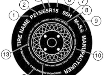
Information on “P” type tires P215/65R15 95H is an example of a tire size, load index and speed rating. The definitions of these items are listed below. (Note that the tire size, load index and speed rating for your vehicle may be different from this example.) 1. P: Indicates a tire, designated by the Tire and Rim Association (T&RA), that may be used for service on cars, SUVs, minivans and light trucks. Note: If your tire size does not begin with a letter this may mean it is designated by either ETRTO (European Tire and Rim Technical Organization) or JATMA (Japan Tire Manufacturing Association). 2. 215: Indicates the nominal width of the tire in millimeters from sidewall edge to sidewall edge. In general, the larger the number, the wider the tire. 3. 65: Indicates the aspect ratio which gives the tire’s ratio of height to width. 4. R: Indicates a “radial” type tire. 5. 15: Indicates the wheel or rim diameter in inches. If you change your wheel size, you will have to purchase new tires to match the new wheel diameter. 6. 95: Indicates the tire’s load index. It is an index that relates to how much weight a tire can carry. You may find this information in your Owner’s Guide. If not, contact a local tire dealer. Note: You may not find this information on all tires because it is not required by federal law. 7. H: Indicates the tire’s speed rating. The speed rating denotes the speed at which a tire is designed to be driven for extended periods of time under a standard condition of load and inflation pressure. The tires on your vehicle may operate at different conditions for load and inflation pressure. These speed ratings may need to be adjusted for the difference in conditions. The ratings range from 81 mph (130 km/h) to 186 mph (299 km/h). These ratings are listed in the following chart.
143
2006 F-250/350/450/550 (f23) Owners Guide (post-2002-fmt) USA (fus)
Tires, Wheels and Loading
Note: You may not find this information on all tires because it is not required by federal law.
Letter rating
Speed rating - mph (km/h)
81 mph (130 km/h) 87 mph (140 km/h) 99 mph (159 km/h) 106 mph (171 km/h) 112 mph (180 km/h) 118 mph (190 km/h) 124 mph (200 km/h) 130 mph (210 km/h) 149 mph (240 km/h) 168 mph (270 km/h) 186 mph (299 km/h) Note: For tires with a maximum speed capability over 149 mph (240 km/h), tire manufacturers sometimes use the letters ZR. For those with a maximum speed capability over 186 mph (299 km/h), tire manufacturers always use the letters ZR. 8. U.S. DOT Tire Identification Number (TIN): This begins with the letters “DOT” and indicates that the tire meets all federal standards. The next two numbers or letters are the plant code designating where it was manufactured, the next two are the tire size code and the last four numbers represent the week and year the tire was built. For example, the numbers 317 mean the 31st week of 1997. After 2000 the numbers go to four digits. For example, 2501 means the 25th week of 2001. The numbers in between are identification codes used for traceability. This information is used to contact customers if a tire defect requires a recall. 9. M+S or M/S: Mud and Snow, or AT: All Terrain, or AS: All Season. 10. Tire Ply Composition and Material Used: Indicates the number of plies or the number of layers of rubber-coated fabric in the tire tread and sidewall. Tire manufacturers also must indicate the ply materials in the tire and the sidewall, which include steel, nylon, polyester, and others.
144
2006 F-250/350/450/550 (f23) Owners Guide (post-2002-fmt) USA (fus)
Tires, Wheels and Loading
11. Maximum Load: Indicates the maximum load in kilograms and pounds that can be carried by the tire. Refer to the Tire Label or Safety Compliance Certification Label, which is located on the B-Pillar or the edge of the driver’s door, for the correct tire pressure for your vehicle. 12. Treadwear, Traction and Temperature Grades • Treadwear: The treadwear grade is a comparative rating based on the
wear rate of the tire when tested under controlled conditions on a specified government test course. For example, a tire graded 150
would wear one and one-half (11⁄2) times as well on the government course as a tire graded 100. • Traction: The traction grades, from highest to lowest are AA, A, B,and C. The grades represent the tire’s ability to stop on wet pavement as measured under controlled conditions on specified government test surfaces of asphalt and concrete. A tire marked C may have poor traction performance.
• Temperature: The temperature grades are A (the highest), B and C, representing the tire’s resistance to the generation of heat and its ability to dissipate heat when tested under controlled conditions on a specified indoor laboratory test wheel.
13. Maximum Permissible Inflation Pressure: Indicates the tire manufacturers’ maximum permissible pressure and/or the pressure at which the maximum load can be carried by the tire. This pressure is normally higher than the manufacturer’s recommended cold inflation pressure which can be found on either the Tire Label or Safety Compliance Certification Label which is located on the B-Pillar or the edge of the driver’s door. The cold inflation pressure should never be set lower than the recommended pressure on the vehicle label. The tire suppliers may have additional markings, notes or warnings such as standard load, radial tubeless, etc.
145
2006 F-250/350/450/550 (f23) Owners Guide (post-2002-fmt) USA (fus)
Tires, Wheels and Loading
Additional information contained on the tire sidewall for “LT” type tires “LT” type tires have some additional information beyond those of “P” type tires; these differences are described below: 1. LT: Indicates a tire, designated by the Tire and Rim Association (T&RA), that is intended for service on light trucks. 2. Load Range/Load Inflation Limits: Indicates the tire’s load-carrying capabilities and its inflation limits. 3. Maximum Load Dual lb. (kg) at psi (kPa) cold: Indicates the maximum load and tire pressure when the tire is used as a dual; defined as four tires on the rear axle (a total of six or more tires on the vehicle). 4. Maximum Load Single lb. (kg) at psi (kPa) cold: Indicates the maximum load and tire pressure when the tire is used as a single; defined as two tires (total) on the rear axle.
146
2006 F-250/350/450/550 (f23) Owners Guide (post-2002-fmt) USA (fus)
Tires, Wheels and Loading
Information on “T” type tires “T” type tires have some additional information beyond those of “P” type tires; these differences are described below: T145/80D16 is an example of a tire size. Note: The temporary tire size for your vehicle may be different from this example. 1. T: Indicates a type of tire, designated by the Tire and Rim Association (T&RA), that is intended for temporary service on cars, SUVs, minivans and light trucks. 2. 145: Indicates the nominal width of the tire in millimeters from sidewall edge to sidewall edge. In general, the larger the number, the wider the tire. 3. 80: Indicates the aspect ratio which gives the tire’s ratio of height to width. Numbers of 70 or lower indicate a short sidewall. 4. D: Indicates a “diagonal” type tire. R: Indicates a “radial” type tire. 5. 16: Indicates the wheel or rim diameter in inches. If you change your wheel size, you will have to purchase new tires to match the new wheel diameter.
Location of the Tire Label or Safety Compliance Certification Label You will find a Tire Label or Safety Compliance Certification Label containing tire inflation pressure by tire size and other important information located on the B-Pillar or the edge of the driver’s door. Refer to the payload description and graphic in the Vehicle loading — with and without a trailer section.
147
2006 F-250/350/450/550 (f23) Owners Guide (post-2002-fmt) USA (fus)
Tires, Wheels and Loading
SNOW TIRES AND CHAINS
Snow tires must be the same size and grade as the tires you currently have on your vehicle.
Note: If your vehicle is equipped with 20” tires, do not use snow chains on the front tires. The tires on your vehicle have all weather treads to provide traction in rain and snow. However, in some climates, you may need to use snow tires and chains. If you need to use chains, it is recommended that steel wheels (of the same size and specifications) be used, as chains may chip aluminum wheels. Follow these guidelines when using snow tires and chains: • Use only SAE Class S chains. • Install chains securely, verifying that the chains do not touch any • Drive cautiously. If you hear the chains rub or bang against your
wiring, brake lines or fuel lines.
vehicle, stop and re-tighten the chains. If this does not work, remove the chains to prevent damage to your vehicle.
• If possible, avoid fully loading your vehicle. • Remove the tire chains when they are no longer needed. Do not use • The suspension insulation and bumpers will help prevent vehicle damage. Do not remove these components from your vehicle when using snow tires and chains.
tire chains on dry roads.
VEHICLE LOADING – WITH AND WITHOUT A TRAILER This section will guide you in the proper loading of your vehicle and/or trailer, to keep your loaded vehicle weight within its design rating capability, with or without a trailer. Properly loading your vehicle will provide maximum return of vehicle design performance. Before loading your vehicle, familiarize yourself with the following terms for determining your vehicle’s weight ratings, with or without a trailer, from the vehicle’s Tire Label or Safety Compliance Certification Label: Base Curb Weight – is the weight of the vehicle including a full tank of fuel and all standard equipment. It does not include passengers, cargo, or optional equipment.
148
2006 F-250/350/450/550 (f23) Owners Guide (post-2002-fmt) USA (fus)
Tires, Wheels and Loading
Vehicle Curb Weight – is the weight of your new vehicle when you picked it up from your authorized dealer plus any aftermarket equipment.
Payload – is the combined weight of cargo and passengers that the vehicle is carrying. The maximum payload for your vehicle can be found on the Tire Label (vehicles exported outside the U.S. and Canada may not have a Tire Label) on the B-Pillar or the edge of the driver’s door. Look for “THE COMBINED WEIGHT OF OCCUPANTS AND CARGO SHOULD NEVER EXCEED XXX kg OR XXX lb.” for maximum payload. The payload listed on the Tire Label or Safety Compliance Certification Label is the maximum payload for the vehicle as built by the assembly plant. If any aftermarket or authorized dealer installed equipment has been installed on the vehicle, the weight of the equipment must be subtracted from the payload listed on the Tire Label or Safety Compliance Certification Label in order to determine the new payload.
The appropriate loading capacity of your vehicle can be limited either by volume capacity (how much space is available) or by payload capacity (how much weight the vehicle should carry). Once you have reached the maximum payload of your vehicle, do not add more cargo, even if there is space available. Overloading or improperly loading your vehicle can contribute to loss of vehicle control and vehicle rollover.
149
2006 F-250/350/450/550 (f23) Owners Guide (post-2002-fmt) USA (fus)
Tires, Wheels and Loading
Example only:
Cargo Weight – includes all weight added to the Base Curb Weight, including cargo and optional equipment. When towing, trailer tongue load or king pin weight is also part of cargo weight. GAW (Gross Axle Weight) – is the total weight placed on each axle (front and rear) – including vehicle curb weight and all payload.
150
2006 F-250/350/450/550 (f23) Owners Guide (post-2002-fmt) USA (fus)
Tires, Wheels and Loading
GAWR (Gross Axle Weight Rating) – is the maximum allowable weight that can be carried by a single axle (front or rear). These numbers are shown on the Tire Label or Safety Compliance Certification Label located on the B-Pillar or the edge of the driver’s door. The total load on each axle must never exceed its GAWR.
Exceeding the Tire Label or Safety Compliance Certification Label axle weight rating limits could result in substandard
vehicle handling or performance, engine, transmission and/or structural damage, serious damage to the vehicle, loss of control and personal injury.
Note: For trailer towing information refer to Trailer towing found in this chapter or the RV and Trailer Towing Guide provided by your authorized dealer.
GVW (Gross Vehicle Weight) – is the Vehicle Curb Weight + cargo + passengers.
151
2006 F-250/350/450/550 (f23) Owners Guide (post-2002-fmt) USA (fus)
Tires, Wheels and Loading
GVWR (Gross Vehicle Weight Rating) – is the maximum allowable weight of the fully loaded vehicle (including all options, equipment, passengers and cargo). The GVWR is shown on the Tire Label or Safety Compliance Certification Label located on the B-Pillar or the edge of the driver’s door. The GVW must never exceed the GVWR.
Exceeding the Tire Label or Safety Compliance Certification Label vehicle weight rating limits could result in substandard
vehicle handling or performance, engine, transmission and/or structural damage, serious damage to the vehicle, loss of control and personal injury.
GCW (Gross Combined Weight) – is the weight of the loaded vehicle (GVW) plus the weight of the fully loaded trailer. GCWR (Gross Combined Weight Rating) – is the maximum allowable weight of the vehicle and the loaded trailer – including all cargo and passengers – that the vehicle can handle without risking damage. (Important: The towing vehicles’ braking system is rated for operation at GVWR, not at GCWR. Separate functional brakes should be used for safe control of towed vehicles and for trailers where the GCW of the towing vehicle plus the trailer exceed the GVWR of the towing vehicle. The GCW must never exceed the GCWR.
152
2006 F-250/350/450/550 (f23) Owners Guide (post-2002-fmt) USA (fus)
Tires, Wheels and Loading
Maximum Loaded Trailer Weight – is the highest possible weight of a fully loaded trailer the vehicle can tow. It assumes a vehicle with only mandatory options, no cargo (internal or external), a tongue load of 10–15% (conventional trailer) or king pin weight of 15–25% (fifth wheel trailer), and driver only (150 lb. [68 kg]). Consult your authorized dealer (or the RV and Trailer Towing Guide provided by your authorized dealer) for more detailed information. Tongue Load or Fifth Wheel King Pin Weight – refers to the amount of the weight that a trailer pushes down on a trailer hitch. Examples: For a 5,000 lb. (2,268 kg) conventional trailer, multiply 5,000
by 0.10 and 0.15 to obtain a proper tongue load range of 500 to 750 lb. (227 to 340 kg). For an 11,500 lb. (5,216 kg) fifth wheel trailer, multiply by 0.15 and 0.25 to obtain a proper king pin load range of 1,725 to 2,875 lb. (782 to 1,304 kg)Do not exceed the GVWR or the GAWR specified on the Tire Label or Safety Compliance Certification Label.
Do not use replacement tires with lower load carrying capacities than the originals because they may lower the vehicle’s GVWR and GAWR limitations. Replacement tires with a higher limit than the originals do not increase the GVWR and GAWR limitations.
Exceeding any vehicle weight rating limitation could result in serious damage to the vehicle and/or personal injury.
Steps for determining the correct load limit: 1. Locate the statement “The combined weight of occupants and cargo should never exceed XXX kg or XXX lbs.” on your vehicle’s placard. 2. Determine the combined weight of the driver and passengers that will be riding in your vehicle. 3. Subtract the combined weight of the driver and passengers from XXX kg or XXX lbs. 4. The resulting figure equals the available amount of cargo and luggage load capacity. For example, if the “XXX” amount equals 1,400 lbs. and there will be five 150 lb. passengers in your vehicle, the amount of available cargo and luggage load capacity is 650 lbs. (1,400–750 (5 x 150) = 650 lb.). In metric units (635–340 (5 x 68) = 295 kg.)
153
2006 F-250/350/450/550 (f23) Owners Guide (post-2002-fmt) USA (fus)
Tires, Wheels and Loading
5. Determine the combined weight of luggage and cargo being loaded on the vehicle. That weight may not safely exceed the available cargo and luggage load capacity calculated in Step 4. 6. If your vehicle will be towing a trailer, load from your trailer will be transferred to your vehicle. Consult this manual to determine how this reduces the available cargo and luggage load capacity of your vehicle. The following gives you a few examples on how to calculate the available amount of cargo and luggage load capacity: • Another example for your vehicle with 1,400 lb. (635 kg) of cargo and
luggage capacity. You decide to go golfing. Is there enough load capacity to carry you, 4 of your friends and all the golf bags? You and four friends average 220 lb. (99 kg) each and the golf bags weigh approximately 30 lb. (13.5 kg) each. The calculation would be: 1,400 – (5 x 220) – (5 x 30) = 1,400 – 1,100 – 150 = 150 lb. Yes, you have enough load capacity in your vehicle to transport four friends and your golf bags. In metric units, the calculation would be: 635 kg — (5
x 99 kg) — (5 x 13.5 kg) = 635 — 495 — 67.5 = 72.5 kg. • A final example for your vehicle with 1,400 lb. (635 kg) of cargo and luggage capacity. You and one of your friends decide to pick up cement from the local home improvement store to finish that patio you have been planning for the past 2 years. Measuring the inside of the vehicle with the rear seat folded down, you have room for 12-100
lb. (45 kg) bags of cement. Do you have enough load capacity to transport the cement to your home? If you and your friend each weigh 220 lb. (99 kg), the calculation would be: 1,400 – (2 x 220) – (12 x 100) = 1,400 – 440 – 1,200 = – 240 lb. No, you do not have enough cargo capacity to carry that much weight. In metric units, the calculation would be: 635 kg — (2 x 99 kg) — (12 x 45 kg) = 635 — 198 — 540 = —103 kg. You will need to reduce the load weight by at least 240 lb. (104 kg). If you remove 3-100 lb. (45 kg) cement bags, then the load calculation would be: 1,400 – (2 x 220) – (9 x 100) = 1,400 – 440 – 900 = 60 lb. Now you have the load capacity to transport the cement and your friend home. . In metric units, the calculation would be: 635 kg — (2 x 99 kg) — (9
x 45 kg) = 635 — 198 — 405 = 32 kg.The above calculations also assume that the loads are positioned in your vehicle in a manner that does not overload the Front or the Rear Gross Axle Weight Rating specified for your vehicle on the Tire Label or Safety Compliance Certification Label found on the edge of the driver’s door.
154
2006 F-250/350/450/550 (f23) Owners Guide (post-2002-fmt) USA (fus)
Tires, Wheels and Loading
Special loading instructions for owners of pickup trucks and utility-type vehicles
For important information regarding safe operation of this type of vehicle, see the Preparing to drive your vehicle section in
the Driving chapter of this owner guide.
Loaded vehicles may handle differently than unloaded vehicles. Extra precautions, such as slower speeds and increased stopping
distance, should be taken when driving a heavily loaded vehicle.
Your vehicle can haul more cargo and people than most passenger cars. Depending upon the type and placement of the load, hauling cargo and people may raise the center of gravity of the vehicle.
TRAILER TOWING Your vehicle may tow a Conventional/Class IV trailer or fifth wheel trailer provided the maximum trailer weight is less than or equal to the maximum trailer weight listed for your engine and rear axle ratio on the following charts. To calculate your maximum trailer weight: For pickup trucks: Take curb weight, hitch hardware and the driver’s weight, then subtract them from the GCWR listed for your vehicle series, engine, transmission and drive axle ratio (refer to the chart/table in the following text). This calculation will give you the maximum trailer weight possible for your vehicle. For chassis cabs and pickup trucks with aftermarket equipment: Weigh your vehicle at a certified scale and subtract this actual curb weight, hitch hardware, and the driver’s weight from the GCWR listed for your vehicle series, engine, transmission and drive axle ratio (refer to the chart/table in the following text). This calculation will give you the maximum trailer weight possible for your vehicle. The weight of all additional cargo and passengers must be subtracted from the maximum trailer weight calculated above. Further trailer/hitch restrictions and limitations exist depending on the type of trailer and hitch used. These additional maximum trailer weight and tongue load limitations are listed in the chart/table that follows the listing of GCWRs.
155
2006 F-250/350/450/550 (f23) Owners Guide (post-2002-fmt) USA (fus)
Tires, Wheels and Loading
Towing a trailer places an additional load on your vehicle’s engine, transmission, axle, brakes, tires and suspension. Inspect these components carefully prior to and after any towing operation. Refer to Transmission temperature gauge in the Instrument Cluster chapter for the transmission fluid temperature information. The following trailer towing charts apply to vehicles equipped with gasoline engines; for vehicles equipped with diesel engines, refer to your 6.0 Liter Power Stroke Direct Injection Turbo Diesel Owner’s Guide Supplement. Note: Do not exceed the GCWR listed for your vehicle on the following chart/table, or the GVWR, GAWR or tire ratings specified on the Tire Label or Safety Compliance Certification Label.
Towing trailers beyond the maximum recommended trailer weight which exceeds the limit of the vehicle’s GCWR, GVWR,
GAWR or tire ratings could result in engine damage, transmission damage, structural damage, loss of vehicle control, vehicle rollover and personal injury.
Maximum GCWR - lb. (kg.)
Engine
Rear axle ratio
Manual
transmission
Automatic
transmission
F–250/F–350 Single Rear Wheel (SRW)
5.4L
6.8L (F-250)
6.8L (F-350)
5.4L
6.8L
3.73
4.10
4.10
4.30
4.10
4.3015000 (6804) 17000 (7711) 20000 (9072) 22000 (9979) 20000 (9072) 22000 (9979)
F–350 Dual Rear Wheel (DRW)
3.73
4.10
4.10
4.3015000 (6804) 17500 (7938) 20500 (9299) 22500 (10206)
F–450/F–550
16000 (7257) 18000 (8165) 21000 (9525) 22500 (10206) 21000 (9525) 23000 (10433)
16500 (7484) 18500 (8391) 21500 (9752) 23000 (10433)
6.8L
4.88/5.38
26000 (11793)
26000 (11793)
156
2006 F-250/350/450/550 (f23) Owners Guide (post-2002-fmt) USA (fus)
Tires, Wheels and Loading
Preparing to tow Use the proper equipment for towing a trailer and make sure it is properly attached to your vehicle. See your authorized dealer or a reliable trailer dealer if you require assistance.
Hitches Do not use hitches that clamp onto the vehicle’s bumper or attach to the axle. You must distribute the load in your trailer so that 10%–15% for conventional towing or 15%-25% fifth-wheel towing of the total weight of the trailer is on the tongue. Integrated hitch rating The standard integrated hitch has two ratings depending on mode of operation: • Weight carrying - requires a draw bar and hitch ball. The draw bar • Weight distributing - requires an aftermarket weight distributing system which includes draw bar, hitch ball, spring bars and snap-up brackets. The vertical tongue load of the trailer is distributed between the truck and the trailer by this system.
supports all the vertical tongue load of the trailer.
Hitch Type
Maximum
Gross Trailer Weight — lb.
(kg)
Maximum
Tongue Weight
— lb. (kg)
6.8L DRW Pickup 2.5” ID without adapter (requires 2.5” drawbar) 6.8L DRW Pickup 2.5” ID with adapter (requires 2” drawbar) All SRW Pickups and 5.4L DRW Pickups 2” receiver
Weight carrying
8000 (3629)
800 (363)
Weight distributing
15000 (6804)
1500 (680)
Weight carrying
6000 (2721)
600 (272)
Weight distributing
12500 (5670)
1250 (567)
Weight carrying
6000 (2721)
600 (272)
Weight distributing
12500 (5670)
1250 (567)
157
2006 F-250/350/450/550 (f23) Owners Guide (post-2002-fmt) USA (fus)
Tires, Wheels and Loading
Towing trailers beyond the maximum tongue weight exceeds the limit of the towing system and could result in vehicle structural
damage, loss of vehicle control and personal injury.
Load equalizing hitch When hooking up a trailer using a load equalizing hitch, always use the following procedure: 1. Park the unloaded vehicle on a level surface. With the ignition on and all doors closed, allow the vehicle to stand for several minutes so that it can level. 2. Measure the height of a reference point on the front and rear bumpers at the center of the vehicle. 3. Attach the trailer to the vehicle and adjust the hitch equalizers so that the front bumper height is within 1⁄2” (13 mm) of the reference point. After proper adjustment, the rear bumper should be no higher than in Step 2. Note: Adjusting an equalizing hitch so the rear bumper of the vehicle is higher than it was unloaded will defeat the function of the load equalizing hitch and may cause unpredictable handling.
Safety chains Always connect the trailer’s safety chains to the frame or hook retainers of the vehicle hitch. To connect the trailer’s safety chains, cross the chains under the trailer tongue and allow slack for turning corners. If you use a rental trailer, follow the instructions that the rental agency gives to you. Do not attach safety chains to the bumper.
Trailer brakes Electric brakes and manual, automatic or surge-type trailer brakes are safe if installed properly and adjusted to the manufacturer’s specifications. The trailer brakes must meet local and Federal regulations.
If you own a trailer with a hydraulic brake system, do not connect the trailer’s hydraulic brake system directly to your
vehicle’s brake system. The vehicle’s brake system is only designed to carry the appropriate amount of brake fluid for the vehicle alone. Connecting a hydraulic trailer braking system could adversely affect your vehicle’s braking performance.
158
2006 F-250/350/450/550 (f23) Owners Guide (post-2002-fmt) USA (fus)
Tires, Wheels and Loading
The braking system of the tow vehicle is rated for operation at the GVWR not GCWR. Integrated trailer brake controller (if equipped) Your vehicle may be equipped with a fully integrated electronic Trailer Brake Controller (TBC). When used properly, the TBC helps ensure smooth and effective trailer braking by powering the trailer’s electric brakes with a proportional output based on the towing vehicle’s brake pressure.
The Ford TBC has only been verified to be compatible with trailers having electric-actuated drum brakes (one to four axles) and not hydraulic surge or electric-over-hydraulic types. It is the responsibility of the customer to ensure that the trailer brakes are adjusted appropriately, functioning normally and all electric connections are properly made.
The TBC user interface consists of the following: 1. +/- (GAIN adjustment buttons): Pressing these buttons will adjust the TBC’s power output to the trailer brakes (in 0.5
increments). The GAIN setting can be increased to a maximum of 10.0
or decreased to a minimum of 0 (no trailer braking). Pressing and holding a button will raise or lower the setting continuously. 2. Trailer connection indicator: This lamp indicates trailer electrical connection status. • When a successful trailer connection is detected, the indicator will be • If the electrical connection is lost, the indicator will flash red. If thegreen.
connection is lost while the vehicle is stationary, the indicator will turn off after 30 seconds. If the connection is lost while the vehicle is moving, the indicator will flash until the ignition is turned off, then on again. • If no electrical connection is detected after the ignition is turned on, pressing a GAIN adjustment button will display the GAIN setting. Sliding the manual control will display the GAIN setting, OUTPUT bar graph and light the trailer indicator red.
159
2006 F-250/350/450/550 (f23) Owners Guide (post-2002-fmt) USA (fus)
Tires, Wheels and Loading
3. GAIN setting display: Shows the current GAIN setting. This will illuminate when a trailer is connected, flash if the trailer becomes disconnected, or remain off if no trailer is connected. 4. OUTPUT bar graph: When the vehicle’s brake pedal is pushed, or when the manual control is activated, green bar indicators will illuminate to indicate the amount of power going to the trailer brakes relative to the brake pedal or manual control input. 5. Manual control lever: Slide the control lever to the left to activate power to the trailer’s electric brakes independent of the tow vehicle’s brakes (see the following Procedure for adjusting GAIN section for instructions on proper use of this feature). If the manual control is activated while the brake is also applied, the greater of the two inputs determines the power sent to the trailer brakes. • Stop Lamps: Activating the TBC manual control lever will illuminate both the trailer brake lamps and the tow vehicle brake lamps (presuming proper trailer electrical connection). Pressing the vehicle brake pedal will also illuminate both trailer and vehicle brake lamps.
GAIN The GAIN setting is used to set the TBC for the specific towing condition and should be changed as towing conditions change. Changes to towing conditions include trailer load, vehicle load, road conditions and weather. The GAIN should be set to provide the maximum trailer braking assistance while ensuring the trailer wheels do not lock when braking. Locked trailer wheels may lead to trailer instability. Procedure for adjusting GAIN: Note: This should only be performed in a traffic free environment at speeds of approximately 20 – 25 mph (30 – 40 km/h). 1. Make sure the trailer brakes are in good working condition, functioning normally, and properly adjusted. See your trailer dealer if necessary. 2. Hook-up the trailer and make the electrical connections according to the trailer manufacturer’s instructions. 3. When a trailer with electric brakes is plugged in, the trailer connection indicator will illuminate green on the TBC and the GAIN setting display will illuminate. 4. Use the GAIN adjustment (+/-) buttons to increase or decrease the GAIN setting to the desired starting point. (A GAIN setting of 6.0 is a good starting point for heavier loads.)
160
2006 F-250/350/450/550 (f23) Owners Guide (post-2002-fmt) USA (fus)
Tires, Wheels and Loading
5. In a traffic-free environment, tow the trailer on a dry, level surface at a speed of 20 – 25 mph (30 – 40 km/h) and squeeze the manual control lever completely. 6. If the trailer wheels lock-up (indicated by squealing tires), reduce the GAIN setting; if the trailer wheels turn freely, increase the GAIN setting. Repeat Steps 5 and 6 until the GAIN setting is at a point just below trailer wheel lock-up. If towing a heavier trailer, trailer wheel lockup may not be attainable even with the maximum GAIN setting of 10. Explanation of instrument cluster messages: The TBC interacts with the instrument cluster message center. These messages, accompanied by a single chime, will be displayed when the TBC determines a malfunction in the trailer connection, TBC system, or in the trailer. These messages are listed below: TRAILER DISCONNECTED (if equipped with message center) or CHECK TRAILER (if equipped with mini message center): This message is displayed when a trailer connection was determined and then a disconnection, either intentionally or unintentionally, has been sensed during a given ignition cycle. It is also displayed if a trailer fault occurs causing the trailer to appear disconnected. This message is also displayed during manual activation without a trailer connected. TBC FAULT: This message is displayed in response to faults sensed by the TBC. In the event this message is seen, please take your vehicle to an authorized dealer for diagnosis and repair. The TBC may still function, but performance may be degraded. TRAILER FAULT: The TBC is capable of determining certain faults in the vehicle wiring and trailer wiring/brake system. These faults do not mean there is anything wrong with the TBC. This message is displayed when one of the following faults has occurred: • Short circuit on the electric brake output wire: If the TRAILER FAULT message is displayed with no trailer connected, the problem is with the vehicle wiring from the TBC to the 7–pin connector in the bumper. If the message is only displayed with a trailer connected, the problem is related to the trailer wiring; consult your trailer dealer for assistance. This can be a short to ground (i.e., chaffed wire) or a short to voltage (i.e., pulled pin on trailer emergency break-away battery).
• Trailer brake overload: The trailer brakes are drawing too much
current; consult your trailer dealer for assistance.
Note: Your TBC can be diagnosed by your authorized dealer to determine exactly which trailer fault has occurred; however, if the fault is with the trailer this diagnosis is not covered under your Ford warranty.
161
2006 F-250/350/450/550 (f23) Owners Guide (post-2002-fmt) USA (fus)
Tires, Wheels and Loading
Points to Remember: • Remember to adjust gain setting before using the TBC for the first • Readjust GAIN setting on the TBC (according to procedure above)
time.
whenever road, weather and trailer or vehicle loading conditions change from those that existed when the gain was initially set. • The sliding lever on the TBC should be used only for manual
activation of trailer brakes to assist with proper adjustment of the GAIN. Misuse, such as application during trailer sway, could cause instability of trailer and/or tow vehicle.
• Avoid towing in adverse weather conditions. The TBC does not provide anti-lock control of the trailer wheels. Trailer wheels can lock-up on slippery surfaces, resulting in reduced stability of trailer and tow vehicle. • The TBC interacts with the brake system of the vehicle, including
ABS, in order to reduce the likelihood of trailer wheel lockup. Therefore, if these systems are not functioning properly the TBC may not function at full performance.
• When the vehicle is turned off, the TBC Output is disabled and the display is shut down. Reactivation of the ignition from 3 (OFF) to 4
(ON) will awaken the TBC module.• The TBC is only a factory or dealer installed item. Ford is not
responsible for warranty or performance of the TBC due to misuse or customer installation.
Trailer lamps Trailer lamps are required on most towed vehicles. Make sure all running lights, brake lights, turn signals and hazard lights are working. See your authorized dealer or trailer rental agency for proper instructions and equipment for hooking up trailer lamps.
Using a step bumper (if equipped) The rear bumper is equipped with an integral hitch and only requires a ball with a one inch (25.4 mm) shank diameter. The bumper has a 5,000
lb. (2,270 kg) trailer weight and 500 lb. (227 kg) tongue weight capacity. If it is necessary to relocate the trailer hitch ball position, a frame-mounted trailer hitch must be installed.162
2006 F-250/350/450/550 (f23) Owners Guide (post-2002-fmt) USA (fus)
Tires, Wheels and Loading
Driving while you tow When towing a trailer: • Do not drive faster than 70 mph (112 km/h) during the first 500 miles (800 km) of trailer towing and don’t make full-throttle starts. • Turn off the speed control. The speed control may shut off automatically when you are towing on long, steep grades. • Consult your local motor vehicle speed regulations for towing a trailer. • To eliminate excessive transmission shifting, activate the Tow/Haul feature. This will also assist in transmission cooling. (For additional information, refer to the Understanding the positions of the 5–speed automatic transmission section in this chapter.
• Anticipate stops and brake gradually. • Do not exceed the GCWR rating or transmission damage may occur. • Your vehicle may be equipped with a temporary or conventional spare tire. If the spare tire is different in size (diameter and/or width), tread type (All-Season or All-Terrain) or is from a different manufacturer other than the road tires on your vehicle, your spare tire is considered “temporary”. Consult information on the spare Tire Label or Safety Compliance Certification Label for limitations when using.
Servicing after towing If you tow a trailer for long distances, your vehicle will require more frequent service intervals. Refer to your scheduled maintenance information for more information.
are securely fastened.
Trailer towing safety tips General • Ensure that the trailer, safety chains and 7–pin electrical connectors • Make sure the truck receiver, draw bar, and coupler are properly • Check rear view and side mirrors for proper visibility especially when • When towing, operate the vehicle at lower speeds than you would
towing trailer wider than the truck.
connected and adjusted.
when not towing a trailer. The likelihood of trailer sway is greater at higher speeds.
163
2006 F-250/350/450/550 (f23) Owners Guide (post-2002-fmt) USA (fus)
Tires, Wheels and Loading • If you will be towing a trailer frequently in hot weather, hilly
conditions, at GCW, or any combination of these factors, consider refilling your rear axle with synthetic gear lubricant if not already so equipped. Refer to Lubricant Specifications in the Maintenance and specifications chapter for the proper axle lubricant. Remember that regardless of the rear axle lubricant used, do not tow a trailer for the first 500 miles (800 km) of a new vehicle, and that the first 500
miles of towing be done at no faster than 70 mph (112 km/h) with no full-throttle starts. • When turning make wide turns to allow trailer tires to properly clear • Be prepared for trailer sway due to buffeting when larger vehiclesany obstacles.
pass in either direction.
Loading • Keep the center-of-gravity low for best handling. • Trailer loads should be evenly distributed front to back and left to • The load distribution within the trailer should be such that 10% – 15%
right.
of the trailer weight is on the hitch. (15% – 25% for 5th-wheel or gooseneck towing.) • Never exceed truck, trailer, receiver, ball, tongue, tire or coupler
loading recommendations.
Braking • The trailer brakes must be inspected and serviced at intervals
specified by the manufacturer. This includes the shoes, drum and trailer brake magnets. • Electric brakes also require periodic adjustment to keep the shoes