- Download PDF Manual
-
the instrument panel switch is pushed past the detent and when any of the remote entry controls are pressed while the ignition is off. The reading lamps can be turned on by pressing the rocker controls next to each lamp.
MAP LAMPS (IF EQUIPPED) To turn on the map lamps, press the control next to each lamp.
BULBS
Headlamp condensation The headlamps are vented to equalize pressure. When moist air enters the headlamp(s) through the vents, there is a possibility that condensation can occur. This condensation is normal and will clear within 45 minutes of headlamp operation.
45
2006 F-250/350/450/550 (f23) Owners Guide (post-2002-fmt) USA (fus)
Lights
Replacing exterior bulbs Check the operation of all the bulbs frequently.
Function
Number of
bulbs
Trade number
194
H6054
H13/9008
4157K/3157
4157K/3157
3157AK or 3157A
Headlamps (aerodynamic) Headlamps (sealed beam) Park lamp with aerodynamic headlamp Park lamp with sealed beam headlamp Sidemarker Tail/stop/turn/sidemarker Backup High-mount stoplamp Foglamp License plate lamp Cargo lamp Front clearance lamps (2) and Front identification lamps (3) Rear fender clearance* Interior visor lamp (if equipped) Rear identification All replacement bulbs are clear in color except where noted. To replace all instrument panel lights - see your authorized dealer * Dual rear wheels, or if equipped.
922
9145
194
906
1943156K or 3156
W5W 194
194
46
2006 F-250/350/450/550 (f23) Owners Guide (post-2002-fmt) USA (fus)
Lights
Replacing headlamp bulbs (aerodynamic) 1. Make sure that the headlamp control is in the OFF position and open the hood. 2. Remove the four screws from the top and bottom front of the headlamp assembly. 3. Press the retaining clip at the top of the headlamp assembly while pulling the assembly straight out. If removing the lamp is difficult, removing the four screws along the top of the grill will help provide more clearance. 4. Disconnect the electrical connector by squeezing the release tab and pushing the connector forward and then pulling it rearward.
5. Remove the bulb assembly by turning it counterclockwise and pulling it straight out.
Handle a halogen headlamp bulb carefully and keep out of children’s reach. Grasp the bulb only by its plastic base and do not touch the glass. The oil from your hand could cause the bulb to break the next time the headlamps are operated.
Install the new bulb(s) in reverse order.
47
2006 F-250/350/450/550 (f23) Owners Guide (post-2002-fmt) USA (fus)
Lights
Replacing park/turn and sidemarker lamp bulbs (aerodynamic) 1. Make sure that the headlamp control is in the OFF position and open the hood. 2. Remove the four screws from the top and bottom front of the headlamp assembly. 3. Press the retaining clip at the top of the headlamp assembly while pulling the assembly straight out. If removing the lamp is difficult, removing the four screws along the top of the grill will help provide more clearance.
4. Remove the bulb assembly, (1) sidemarker or (2) park/turn by turning it counterclockwise and pulling it straight out. 5. Pull the old bulb out from the socket.
Install the new bulb(s) in reverse order.
48
2006 F-250/350/450/550 (f23) Owners Guide (post-2002-fmt) USA (fus)
Lights
Replacing headlamp bulbs (sealed beam) 1. Make sure that the headlamp control is in the OFF position and open the hood. 2. Remove the four screws from the top and bottom front of the headlamp assembly. 3. Press the retaining clip at the top of the headlamp assembly while pulling the assembly straight out. If removing the lamp is difficult, removing the four screws along the top of the grill will help provide more clearance. 4. Disconnect the electrical connector from the park lamp/bezel. 5. Remove the four screws and the headlamp retaining ring from headlamp.
Install the new bulb(s) in reverse order.
49
2006 F-250/350/450/550 (f23) Owners Guide (post-2002-fmt) USA (fus)
Lights
Replacing park/turn/sidemarker bulbs (sealed beam) 1. Make sure that the headlamp control is in the OFF position and open the hood. 2. Remove the four screws from the top and bottom front of the headlamp assembly. 3. Press the retaining clip at the top of the headlamp assembly while pulling the assembly straight out. If removing the lamp is difficult, removing the four screws along the top of the grill will help provide more clearance.
4. Remove the bulb assembly, (1) sidemarker or (2), park/turn by turning it counterclockwise. 5. Pull the old bulb out from the socket.
Install the new bulb(s) in reverse order.
50
2006 F-250/350/450/550 (f23) Owners Guide (post-2002-fmt) USA (fus)
Lights
Replacing tail lamp/turn/backup lamp bulbs — F–250/F–350 only 1. Make sure the headlamp switch is in the OFF position and then open the tailgate to expose the lamp assemblies. 2. Remove the two bolts from the tail lamp assembly and carefully pull the lamp assembly from the tailgate pillar by releasing the two retaining tabs. 3. Rotate the bulb socket counterclockwise and remove from lamp assembly. 4. Pull the bulb straight out of the socket. Install the new bulb(s) in reverse order. Replacing brake/tail/backup lamp bulbs — F–450/F–550 only 1. Make sure the headlamp switch is in the OFF position. 2. Remove the four screws and the lamp lens from lamp assembly. 3. Carefully pull the bulb straight out of the socket and push in the new bulb.
51
2006 F-250/350/450/550 (f23) Owners Guide (post-2002-fmt) USA (fus)
Lights
Replacing cargo lamp and high-mount brakelamp bulbs 1. Make sure the headlamp switch is in the OFF position. 2. Remove the two screws and lamp assembly from vehicle as wiring permits. 3. Remove the bulb socket by rotating counterclockwise. 4. Pull the bulb straight out of the socket.
Front clearance and identification lamp bulbs 1. Make sure the headlamp switch is in the OFF position. 2. Remove the screw and lens from the lamp assembly. 3. Pull the bulb straight out of the socket.
Install the bulb(s) in reverse order. Replacing foglamp bulbs (if equipped) 1. Make sure the headlamp switch is in the OFF position. 2. Remove the bulb socket from the foglamp by turning counterclockwise. 3. Disconnect the electrical connector from the foglamp bulb. Install the new bulb(s) in reverse order.
52
2006 F-250/350/450/550 (f23) Owners Guide (post-2002-fmt) USA (fus)
Lights
Replacing license plate lamp bulbs The license plate bulbs are located behind the rear bumper. To change the license plate lamp bulbs: 1. Reach behind the rear bumper to locate the bulb. 2. Twist the bulb socket counterclockwise and carefully pull to remove it from the lamp assembly. 3. Pull out the old bulb from the socket and push in the new bulb. 4. Install the bulb socket in lamp assembly by turning it clockwise.
53
2006 F-250/350/450/550 (f23) Owners Guide (post-2002-fmt) USA (fus)
Driver Controls
MULTI-FUNCTION LEVER Windshield wiper: Rotate the end of the control away from you to increase the speed of the wipers; rotate towards you to decrease the speed of the wipers.
Windshield washer: Push the end of the stalk: • briefly: causes a single swipe of the wipers without washer fluid. • a quick push and hold: the wipers
will swipe three times with washer fluid.
• a long push and hold: the wipers
and washer fluid will be activated for up to ten seconds.
TILT STEERING WHEEL (IF EQUIPPED) To adjust the steering wheel: 1. Pull and hold the steering wheel release control toward you. 2. Move the steering wheel up or down until you find the desired location. 3. Release the steering wheel release control. This will lock the steering wheel in position.
Never adjust the steering wheel when the vehicle is moving.
54
2006 F-250/350/450/550 (f23) Owners Guide (post-2002-fmt) USA (fus)
Driver Controls
TRANSMISSION CONTROL Tow/Haul feature (5–speed automatic transmission) (if equipped) To activate, press the transmission control switch (TCS) located on the gearshift. The TOW/HAUL indicator light will illuminate in the instrument cluster. The transmission will operate in all gears. Press the transmission control switch again to deactivate Tow/Haul mode. When you shut off and re-start your vehicle, the transmission will automatically return to normal mode with Tow/Haul feature deactivated, refer to the Driving chapter for more information.
Do not use the Tow/Haul feature when driving in icy or slippery conditions as the increased engine braking can cause the rear
wheels to slide and the vehicle to swing around with the possible loss of vehicle control..
ILLUMINATED VISOR MIRROR (IF EQUIPPED) Lift the mirror cover to turn on the visor mirror lamps.
OVERHEAD CONSOLE (IF EQUIPPED) The appearance of your vehicle’s overhead console will vary according to your option package. If your vehicle is equipped with a moonroof, refer to Moonroof later in this chapter for information on its operation.
55
2006 F-250/350/450/550 (f23) Owners Guide (post-2002-fmt) USA (fus)
Driver Controls
Storage compartment (if equipped) Press the release on the door to open the storage compartment. The storage compartment may be used to secure sunglasses or a similar object and the front tab can be used for holding tickets, paper, envelopes, etc. The front bin may be used to store small objects.
AUXILIARY POWER POINT (12VDC) Power outlets are designed for accessory plugs only. Do not insert any other object in the power outlet for this will damage the outlet and blow the fuse. Do not hang any type of accessory or accessory bracket from the plug. Improper use of the power outlet can cause damage not covered by your warranty. The auxiliary power point is located on the instrument panel. Do not use the power point for operating the cigarette lighter element (if equipped). To prevent the fuse from being blown, do not use the power point(s) over the vehicle capacity of 12 VDC/180W. To prevent the battery from being discharged, do not use the power point longer than necessary when the engine is not running. Always keep the power point caps closed when not being used. Cigar lighter (if equipped) Do not plug optional electrical accessories into the cigarette lighter socket. Do not hold the lighter in with your hand while it is heating, this will damage the lighter element and socket. The lighter will be released from its heating position when it is ready to be used. Improper use of the lighter can cause damage not covered by your warranty.
56
2006 F-250/350/450/550 (f23) Owners Guide (post-2002-fmt) USA (fus)
Driver Controls
POWER WINDOWS (IF EQUIPPED)
Do not leave children unattended in the vehicle and do not let children play with the power windows. They may seriously injure
themselves.
When closing the power windows, you should verify they are free of obstructions and ensure that children and/or pets are not in
the proximity of the window openings.
Press and hold the bottom part of the rocker switch to open the window. Press and hold the top part of the rocker switch to close the window.
One touch down Allows the driver’s window to open fully without holding the control down. Press completely down on AUTO and release quickly. Press again to stop.
Window lock (if equipped) The window lock feature allows only the driver to operate the power windows. To lock out all the window controls except for the driver’s press the left side of the control. Press the right side to restore the window controls.
2006 F-250/350/450/550 (f23) Owners Guide (post-2002-fmt) USA (fus)
57
Driver Controls
Power rear slider window (if equipped) • Press and hold the open arrow side of control to open window. • Press and hold the closed arrow side of control to close window.
Accessory delay (if equipped) With accessory delay, the window switches may be used for up to ten minutes after the ignition switch is turned to the OFF position or until any door is opened.
AUTOMATIC DIMMING INSIDE REAR VIEW MIRROR (IF EQUIPPED) Your vehicle may be equipped with an inside rear view mirror with an auto-dimming function. The electronic day/night mirror will change from the normal state to the non-glare state when bright lights (glare) reach the mirror. When the mirror detects bright light from front or behind, it will automatically adjust to minimize glare. Do not clean the housing or glass of any mirror with harsh abrasives, fuel or other petroleum-based cleaning products.
POWER SIDE VIEW MIRRORS (IF EQUIPPED) To adjust your mirrors: 1. Rotate the control clockwise to adjust the right mirror and rotate the control counterclockwise to adjust the left mirror. 2. Move the control in the direction you wish to tilt the mirror. 3. Return to the center position to lock mirrors in place.
58
2006 F-250/350/450/550 (f23) Owners Guide (post-2002-fmt) USA (fus)
Driver Controls
(if equipped)
Heated outside mirrors The main mirror glass is heated automatically to remove ice, mist and fog and activates when the vehicle is started. Note: The mirrors may be hot to the touch but will not burn. This is a normal condition. Type A The mirror heating elements are designed to operate regardless of the geographic location of the vehicle. There is no switch to turn on, or other operator involvement required other than to start the vehicle. Type B The spotter mirror, below the main mirror, is not heated and must be adjusted manually.
Do not remove ice from the mirrors with a scraper or attempt to readjust the mirror glass if it is frozen in place. These actions could cause damage to the glass and mirrors.
Mirror mounted side turn signal indicator (if equipped) When the vehicle turn signals are activated, the outer portion of the mirror housing will blink amber. The turn signal feature can be seen by other drivers who may approach from the rear of the vehicle.
59
2006 F-250/350/450/550 (f23) Owners Guide (post-2002-fmt) USA (fus)
Driver Controls
Clearance lamps (if equipped) Illuminates when the headlamps or parking lamps are switched on. This provides additional visibility of your vehicle to other drivers on the road.
Fold-away mirrors The mirrors can be manually folded forward or backwards for narrow spaces like driving through an automatic car wash or backing out of a garage with the trailer tow mirror.
The telescoping feature (if equipped) allows the mirror to extend approximately 3.15 inches (80 mm). This feature is especially useful to the driver when towing a trailer.
60
2006 F-250/350/450/550 (f23) Owners Guide (post-2002-fmt) USA (fus)
Driver Controls
POWER ADJUSTABLE FOOT PEDALS (IF EQUIPPED) The accelerator and brake pedal should only be adjusted when the vehicle is stopped and the gearshift lever is in the P (Park) position. Press and hold the rocker control to adjust accelerator and brake pedal toward you or away from you.
The adjustment allows for approximately 2.75 inches (70 mm) of maximum travel.
Never adjust the accelerator and brake pedal with feet on the pedals while the vehicle is moving.
SPEED CONTROL (IF EQUIPPED) With speed control set, you can maintain a speed of 30 mph (48 km/h) or more without keeping your foot on the accelerator pedal. Speed control does not work at speeds below 30 mph (48 km/h).
Do not use the speed control in heavy traffic or on roads that are winding, slippery or unpaved.
Setting speed control The controls for using your speed control are located on the steering wheel for your convenience. 1. Press the ON control and release it. 2. Accelerate to the desired speed.
2006 F-250/350/450/550 (f23) Owners Guide (post-2002-fmt) USA (fus)
ON
OFF
61
Driver Controls
3. Press the SET ACCEL control and release it. 4. Take your foot off the accelerator pedal. 5. The indicator instrument cluster will turn on.
light on the
RES
SET
ACCEL
COAST
steep hill.
Note: • Vehicle speed may vary momentarily when driving up and down a • If the vehicle speed increases above the set speed on a downhill, you • If the vehicle speed decreases more than 10 mph (16 km/h) below
may want to apply the brakes to reduce the speed.
your set speed on an uphill, your speed control will disengage.
Resuming a set speed Press the RES/RESUME control and release it. This will automatically return the vehicle to the previously set speed. The RES/RESUME control will not work if the vehicle speed is not faster than 30 mph (48 km/h).
RES
SET
ACCEL
COAST
Increasing speed while using speed control There are two ways to set a higher speed: • Press and hold the SET ACCEL control until you get to the desired speed, then release the control. You can also use the SET ACCEL control to operate the Tap-Up function. Press and release this control to increase the vehicle set speed in small amounts by 1 mph (1.6 km/h).
• Use the accelerator pedal to get to the desired speed. When the
vehicle reaches that speed press and release the SET ACCEL control.
ACCEL
COAST
RES
SET
62
2006 F-250/350/450/550 (f23) Owners Guide (post-2002-fmt) USA (fus)
Driver Controls
Reducing speed while using speed control There are two ways to reduce a set speed: • Press and hold the COAST control until you get to the desired speed, then release the control. You can also use the COAST control to operate the Tap-Down function. Press and release this control to decrease the vehicle set speed in small amounts by 1 mph (1.6 km/h).
ACCEL
COAST
RES
SET
• Depress the brake pedal until the desired vehicle speed is reached, press the SET ACCEL control.
RES
SET
ACCEL
COAST
Turning off speed control There are two ways to turn off the speed control: • Depress the brake pedal or the clutch pedal (if equipped). This will • Press the speed control OFF
not erase your vehicle’s previously set speed.
control.
Note: When you turn off the speed control or the ignition, your speed control set speed memory is erased.
ON
OFF
Indicator light (if equipped) This light comes on when either the SET ACCEL or RES controls are pressed. The vehicle speed must be at or above 48 km/h (30 mph). It turns off when the speed control OFF control is pressed, the brake or clutch is applied, or the ignition is turned to the OFF position.
63
2006 F-250/350/450/550 (f23) Owners Guide (post-2002-fmt) USA (fus)
Driver Controls
UPFITTER CONTROLS (IF EQUIPPED) Your vehicle may be equipped with the Upfitter option package which will provide four switches, mounted in the center of the instrument panel, labeled AUX 1, AUX 2, AUX 3
and AUX 4. These switches will only operate while the ignition is in the 4
(ON) position, whether the engine is running or not. It is, however, recommended that the engine remain running to maintain battery charge when using the Upfitter switches for extended duration or higher current draws. (This is even more important for vehicles with diesel engines since the glow plugs are also draining battery power when the ignition key is in the 4 [ON] position.) When switched on by the operator they provide 10 amps or 30 amps of electrical battery power for a variety of personal or commercial uses. If your vehicle is equipped with this option, there will also be a relay box with a fuse located inside the glove box.64
2006 F-250/350/450/550 (f23) Owners Guide (post-2002-fmt) USA (fus)
Driver Controls
The relays and fuse in the glove box are coded as shown in the accompanying illustration. There will also be one power lead for each switch found as a blunt-cut and sealed wire located behind the passenger compartment fuse panel.
They are coded as follows:
Switch
Circuit number Wire color
AUX 1
AUX 2
AUX 3AUX 4
1936
1933
19341935
Orange with Light Green Trace Orange Orange with Yellow Trace Orange with Light Blue Trace
Fuse 30A
30A 10A
10A
More detailed information about the Upfitter switches can be found in the Electrical Wiring section of the Ford Truck Body Builders Layout Book, found at www.fleet.ford.com/truckbbas.
65
2006 F-250/350/450/550 (f23) Owners Guide (post-2002-fmt) USA (fus)
Driver Controls
STEERING WHEEL CONTROLS (IF EQUIPPED) These controls allow you to operate some radio and climate control features.
Radio control features • Press MODE to select AM, FM1, FM2, TAPE or CD (if equipped). In Radio mode: • Press NEXT to seek/scan to the
next strong station.
In Tape mode: • Press NEXT to listen to the next
selection on the tape.
In CD mode: • Press NEXT to listen to the next
track on the disc.
In any mode: • Press VOL up or down to adjust
the volume.
NEXT
MODE
Climate control features • Press TEMP up or down to adjust temperature. • Press FAN up or down to adjust fan speed. ONE-TOUCH MOON ROOF (IF EQUIPPED) The moon roof control is located on the overhead console. Note: The moon roof will open to the “comfort” position first before opening all the way. The “comfort” position helps to alleviate rumbling wind noise which may happen in the vehicle with the roof fully opened. To open the moon roof: The moon roof is equipped with a one-touch open feature. Press and release the AUTO control. The moon roof will open to the “comfort” position.
66
2006 F-250/350/450/550 (f23) Owners Guide (post-2002-fmt) USA (fus)
Driver Controls
control again.
control until the glass
Press and release the control again to fully open. To stop the one-touch open feature press either the AUTO or To close the moon roof: Press and hold the panel stops at the “comfort” position. Press and hold the control again until the glass stops moving. When fully closed, the rear portion of the glass panel will appear higher than the front portion. control. The moon To vent the moon roof: Press and hold the roof must be in the closed position in order to move it into the vent position. To close, press and hold the AUTO control until the glass panel stops moving. The moon roof has a built-in sliding shade that can be manually opened or closed when the glass panel is shut. To close the shade, pull it toward the front of the vehicle.
Do not let children play with the moon roof or leave children unattended in the vehicle. They may seriously hurt themselves.
When closing the moon roof, you should verify that it is free of obstructions and ensure that children and/or pets are not in the
proximity of the moon roof opening.
CENTER CONSOLE (IF EQUIPPED) Your vehicle may be equipped with a variety of console features. These include: • Utility compartment with • Coin holder • Pen holder • Writing surface
cassette/CD holder
Use only soft cups in the cupholder. Hard objects can
injure you in a collision.
67
2006 F-250/350/450/550 (f23) Owners Guide (post-2002-fmt) USA (fus)
Driver Controls
MINI-MESSAGE CENTER (IF EQUIPPED) With the ignition in the ON position, the mini message center, located on your instrument cluster, displays text messages that alert you to possible problems or malfunctions in your vehicle’s operating systems. Note: The following warning messages will reappear after an ignition OFF-ON cycle has been completed. Door ajar: Displays when the ignition is in the ON position and any door is open.
Check fuel cap: Displays when the fuel cap may not be properly installed. Continued driving with this display on may cause the Service engine soon warning light to come on. Refer to Fuel filler cap under the Fuel Information section in the Maintenance and Specifications chapter. Trailer fault (if equipped): Displayed if there is a short circuit on the electric brake output wire or the trailer brakes are drawing too much current. Refer to Integrated trailer brake controller in the Tires, Wheels and Loading chapter for more information. TBC fault (if equipped): Displays in response to faults sensed by the TBC. In the event this message is seen, please take your vehicle to an authorized dealer for diagnosis and repair. Refer to Integrated trailer brake controller in the Tires, Wheels and Loading chapter for more information. Note: The following warning messages will reappear on the display every ten minutes. Low fuel: Displays when the fuel level in the fuel tank is at or near empty (refer to Fuel gauge in this chapter).
68
2006 F-250/350/450/550 (f23) Owners Guide (post-2002-fmt) USA (fus)
Driver Controls
is high.
Check gauge: Displays when any of the following conditions has occurred: • The engine coolant temperature • The engine oil pressure is low. • The fuel gauge is at or near empty. Check trailer (if equipped): Displayed when a trailer connection becomes disconnected, either intentionally or unintentionally, and has been sensed during a given ignition cycle. Refer to Integrated trailer brake controller in the Tires, Wheels and Loading chapter for more information. Language The language options are English and French. The feature works as follows: 1. If present language is English, press and hold the SELECT/RESET button for 15 seconds or greater to convert the language selection to French. The word ⬙FRENCH⬙ will be displayed for 4 seconds as a confirmation that language has been changed. 2. If present language is French, press and hold the SELECT/RESET button for 15 seconds or greater to convert the language selection to English. The word ⬙ENGLISH⬙ will be displayed for 4 seconds as a confirmation that language has been changed.
MESSAGE CENTER (IF EQUIPPED) With the ignition in the ON position, the message center, located on your instrument cluster, displays important vehicle information through a constant monitor of vehicle systems. You may select display features on the message center for a display of status preceded by a brief indicator chime. The system will also notify you of potential vehicle problems with a display of system warnings followed by a long indicator chime.
69
2006 F-250/350/450/550 (f23) Owners Guide (post-2002-fmt) USA (fus)
Driver Controls
Selectable features Reset Press this control to select and reset functions shown in the INFO menu and SETUP menu.
Empty/Odometer/Compass
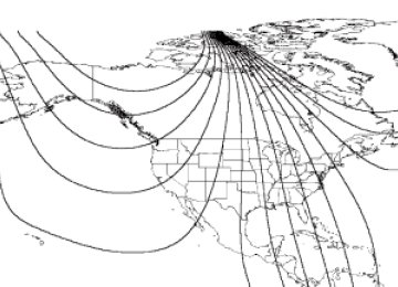
Info menu This control displays the following control displays: • Odometer/Compass • Trip odometer/Odometer/Compass • Distance to • Average Fuel Economy/Odometer/Compass • Engine hour meter/Odometer/Compass Odometer/Trip odometer Refer to Gauges in the Instrument Cluster chapter. Compass display The compass heading is displayed as one of N, NE, E, SE, S, SW, W and NW in the message center display. The compass reading may be affected when you drive near large buildings, bridges, power lines and powerful broadcast antenna. Magnetic or metallic objects placed in, on or near the vehicle may also affect compass accuracy. Usually, when something affects the compass readings, the compass will correct itself after a few days of operating your vehicle in normal conditions. If the compass still appears to be inaccurate, a manual calibration may be necessary. Refer to Compass zone/calibration adjustment. Most geographic areas (zones) have a magnetic north compass point that varies slightly from the northerly direction on maps. This variation is four degrees between adjacent zones and will become noticeable as the vehicle crosses multiple zones. A correct zone setting will eliminate this error. Refer to Compass zone/calibration adjustment.
70
2006 F-250/350/450/550 (f23) Owners Guide (post-2002-fmt) USA (fus)
Driver Controls
23
15
14
13
127 8 9 1011
Compass zone/calibration adjustment 1. Determine your magnetic zone by referring to the zone map. 2. Turn ignition to the ON position. 3. Start the engine.
4. From Info menu, press and hold the SETUP and RESET controls simultaneously until the message center display changes to show the current zone setting (XX). 5. Press the SETUP control repeatedly until the correct zone setting for your geographic location is displayed on the message center. The range of zone values are from 01 to 15 and “wraps” back to 01. 6. To exit the zone setting mode, and to “lock in” your change, press and release the RESET control.
Perform compass calibration in an open area free from steel structures and high voltage lines. For optimum calibration, turn off all electrical accessories (heater/air conditioning, wipers, etc.) and make sure all vehicle doors are shut. 7. Press the RESET control to start the compass calibration function. 8. Slowly drive the vehicle in a circle (less than 3 mph [5 km/h]) until the CIRCLE SLOWLY TO CALIBRATE display changes to CALIBRATION COMPLETED. It will take up to five circles to complete calibration.
71
2006 F-250/350/450/550 (f23) Owners Guide (post-2002-fmt) USA (fus)
Driver Controls
9. The compass is now calibrated.
Distance to empty (DTE) Selecting this function from the INFO menu estimates approximately how far you can drive with the fuel remaining in your tank under normal driving conditions. Remember to turn the ignition OFF when refueling to allow this feature to correctly detect the added fuel. The DTE function will display LOW FUEL LEVEL and sound a tone for one second when you have approximately 50 miles (80 km) to empty. If you RESET this warning message, this display and tone will return within 10 minutes. DTE is calculated using a running average fuel economy, which is based on your recent driving history of 500 miles (800 km). This value is not the same as the average fuel economy display. The running average fuel economy is reinitialized to a factory default value if the battery is disconnected. Average fuel economy (AFE) Select this function from the INFO menu to display your average fuel economy in miles/gallon or liters/100
km. If you calculate your average fuel economy by dividing miles traveled since last fill-up by gallons of fuel used (multiply liters used by 100, then divide by kilometers traveled), your figure may be different than displayed for the following reasons: • Your vehicle was not perfectly level during fill-up • Differences in the automatic shut-off points on the fuel pumps at • Variations in top-off procedure from one fill-up to another • Rounding of the displayed values to the nearest 0.1 gallon (liter)service stations
72
2006 F-250/350/450/550 (f23) Owners Guide (post-2002-fmt) USA (fus)
Driver Controls
1. Drive the vehicle at least 5 miles (8 km) with the speed control system engaged to display a stabilized average. 2. Record the highway fuel economy for future reference. It is important to press the RESET control after setting the speed control to get accurate highway fuel economy readings. Engine hour meter Select this function from the INFO menu to display the accumulated running time of the engine.
Setup menu Press this control for the following displays: • System Check • Units (English/Metric) • Autolock • Autolamp Delay • Language System check Selecting this function from the SETUP menu causes the message center to cycle through each of the systems being monitored. For each of the monitored systems, the message center will indicate either an OK message or a warning message for three seconds. Pressing the RESET control cycles the message center through each of the systems being monitored. The sequence of the system check report and how it appears in the message center is as follows: 1. ENGINE TEMP 2. TRANS TEMP 3. OIL PRESSURE 4. BRAKE FLUID LEVEL
73
2006 F-250/350/450/550 (f23) Owners Guide (post-2002-fmt) USA (fus)
Driver Controls
5. DOOR AJAR 6. FUEL CAP (gasoline engine only) 7. AIR FILTER (diesel engine only) 8. FUEL LEVEL Units (English/Metric) 1. Select this function from the SETUP menu for the current units to be displayed. 2. Press the RESET control to change from English to Metric. Autolocks This feature automatically locks all vehicle doors when the vehicle is shifted into any gear, putting the vehicle in motion. 1. To disable/enable the autolock feature, select this function from the SETUP control for the current display mode. 2. Press the RESET control to turn the autolocks ON or OFF. Autolamp delay This feature keeps your headlights on for up to three minutes after the ignition is switched off. 1. To disable/enable the autolamp delay feature, select this function from the SETUP control for the current display mode. 2. Press the RESET control to select the new Autolamp delay values of >0, >10, >20, >30, >60, >90, >120 or >180.
74
2006 F-250/350/450/550 (f23) Owners Guide (post-2002-fmt) USA (fus)
Driver Controls
Language 1. Select this function from the SETUP menu for the current language to be displayed.
2. Pressing the RESET control cycles the message center through each of the language choices.
3. Press and hold the RESET control to set the language choice.
System warnings System warnings alert you to possible problems or malfunctions in your vehicle’s operating systems. In the event of a multiple warning situation, the message center will cycle the display to show all warnings by displaying each one for 4
seconds. The message center will display the last selected feature if there are no more warning messages. This allows you to use the full functionality of the message center after you acknowledge the warning by pressing the RESET control and clearing the warning message. Warning messages that have been reset are divided into three categories: • They will not disappear until a condition is changed. • They will reappear on the display ten minutes from the reset. • They will not reappear until an ignition OFF-ON cycle has beencompleted.
75
2006 F-250/350/450/550 (f23) Owners Guide (post-2002-fmt) USA (fus)
Driver Controls
Warning returns after 10 minutes
Status Warning cannot be reset
Warning returns after the ignition key is turned from OFF to ON.
This acts as a reminder that these warning conditions still exist within the vehicle. Warning display Reduced engine power Stop engine safely Low fuel level Low brake fluid level Low oil pressure Check engine temperature Trailer disconnected Water in fuel (diesel only) Check air filter (diesel only) Door ajar Check fuel cap Engine failsafe mode Check compass module Trailer fault TBC fault DOOR AJAR. Displayed when a door is not completely closed. CHECK ENGINE TEMPERATURE. Displayed when the engine coolant is overheating. Stop the vehicle as soon as safely possible, turn off the engine and let it cool. Check the coolant and coolant level. Refer to Engine coolant in the Maintenance and Specifications chapter. If the warning stays on or continues to come on, contact your authorized dealer as soon as possible. REDUCED ENGINE POWER. Displayed when the engine is overheating. Stop the vehicle as soon as safely possible, turn off the engine. If the warning stays on followed by an indicator chime or continues to come on, contact your authorized dealer as soon as possible. STOP ENGINE SAFELY. Displayed when the engine is overheating. Stop the vehicle as soon as safely possible, turn off the engine. If the warning stays on followed by an indicator chime or continues to come on, contact your authorized dealer as soon as possible. LOW FUEL LEVEL. Displayed as an early reminder of a low fuel condition.
76
2006 F-250/350/450/550 (f23) Owners Guide (post-2002-fmt) USA (fus)
Driver Controls
LOW BRAKE FLUID LEVEL. Indicates the brake fluid level is low and the brake system should be inspected immediately. Refer to Checking and adding brake fluid in the Maintenance and Specifications chapter. LOW OIL PRESSURE. Displayed when the engine oil pressure is low. If this warning message is displayed, check the level of the engine oil. Refer to Engine oil in the Maintenance and Specifications chapter for information about adding engine oil. If the oil level is OK and this warning persists, shut down the engine immediately and contact your authorized dealer for service. CHECK FUEL CAP. Displayed when the fuel filler cap is not properly installed. Check the fuel filler cap for proper installation. Refer to Fuel filler cap under the Fuel Information section in the Maintenance and Specifications chapter. ENGINE FAILSAFE MODE. Displayed when the engine has defaulted to a ’limp-home’ operation. If the warning stays on or continues to come on, contact your authorized dealer as soon as possible. CHECK COMPASS MODULE. Displayed when the compass is not operating properly. If the warning stays on or continues to come on, contact your authorized dealer as soon as possible. TRAILER DISCONNECTED (if equipped): Displayed when a trailer connection becomes disconnected, either intentionally or unintentionally, and has been sensed during a given ignition cycle. Refer to Integrated trailer brake controller in the Tires, Wheels and Loading chapter for more information. TRAILER FAULT (if equipped): Displayed if there is a short circuit on the electric brake output wire or the trailer brakes are drawing too much current. Refer to Integrated trailer brake controller in the Tires, Wheels and Loading chapter for more information. TBC FAULT (if equipped): Displayed in response to faults sensed by the TBC. In the event this message is seen, please take your vehicle to an authorized dealer for diagnosis and repair. Refer to Integrated trailer brake controller in the Tires, Wheels and Loading chapter for more information. WATER IN FUEL (diesel only): Refer to Instrumentation in your 6.0
Liter Power Stroke Direct Injection Turbo Diesel Owner’s Guide Supplement. CHECK AIR FILTER (diesel only): Refer to Instrumentation in your 6.0 Liter Power Stroke Direct Injection Turbo Diesel Owner’s Guide Supplement.77
2006 F-250/350/450/550 (f23) Owners Guide (post-2002-fmt) USA (fus)
Driver Controls
DATA ERR. These messages indicate improper operation of the vehicle network communication between electronic modules. • Odometer • Fuel flow • Fuel level • Trans temp • Fuel cap • Engine sensor • Brake fluid • Auto lock • Auto lamp delay Contact your authorized dealer as soon as possible if these messages occur on a regular basis.
TAILGATE LOCK (IF EQUIPPED) Your vehicle may be equipped with a tailgate lock designed to prevent theft of the tailgate. • Insert ignition key and turn to the • Turn ignition key to the left to
right to engage lock.
unlock.
78
2006 F-250/350/450/550 (f23) Owners Guide (post-2002-fmt) USA (fus)
Driver Controls
Tailgate removal Your tailgate is removable to allow more room for loading. 1. Lower the tailgate. 2. Use a screwdriver to pry the spring clip (on each connector) past the head of the support screw. Disconnect cable. 3. Disconnect the other cable. 4. Lift tailgate to a 45–degree angle. 5. Lift right side off of its hinge. 6. Lift left side off of its hinge. To install, follow the removal procedures in reverse order.
79
2006 F-250/350/450/550 (f23) Owners Guide (post-2002-fmt) USA (fus)
Locks and Security
KEYS The key operates all locks on your vehicle. You should always carry a second key with you in a safe place in case you require it in an emergency. Your keys are programmed to your vehicle; using a non-programmed key will not permit your vehicle to start. If you lose your authorized dealer supplied keys, replacement keys are available through your authorized dealer.
POWER DOOR LOCKS (IF EQUIPPED) Press control to unlock all doors.
Press control to lock all doors.
Smart locks (if equipped) This feature prevents you from locking yourself out of the vehicle if your key is still in the ignition. When you open the driver’s door and you lock the vehicle with the power door lock control, all the doors will lock, then the driver’s door will automatically unlock reminding you that your key is still in the ignition. The vehicle can still be locked, with the key in the ignition, using the manual lock button on the door, locking the driver’s door with a key, by simultaneously pressing button 7 • 8 and the 9 • 0 controls on the remote entry keypad (if equipped), or using the lock button on the remote entry transmitter (if equipped).
80
2006 F-250/350/450/550 (f23) Owners Guide (post-2002-fmt) USA (fus)
Locks and Security
CHILDPROOF DOOR LOCKS (IF EQUIPPED) • When these locks are set, the
rear doors cannot be opened from the inside.
• The rear doors can be opened
from the outside when the doors are unlocked.
The childproof locks are located on rear edge of each rear door and must be set separately for each door. Setting the lock for one door will not automatically set the lock for both doors. • Move lock control up to engage • Move lock control down to
the childproof lock.
disengage the childproof lock.
REMOTE ENTRY SYSTEM (IF EQUIPPED) This device complies with part 15 of the FCC rules and with RS-210 of Industry Canada. Operation is subject to the following two conditions: (1) This device may not cause harmful interference, and (2) This device must accept any interference received, including interference that may cause undesired operation. Changes or modifications not expressly approved by the party responsible for compliance could void the user’s authority to operate the equipment. The typical operating range for your remote entry transmitter is approximately 33 feet (10 meters). A decrease in operating range could be caused by: • weather conditions, • nearby radio towers, • structures around the vehicle, or • other vehicles parked next to your vehicle.
81
2006 F-250/350/450/550 (f23) Owners Guide (post-2002-fmt) USA (fus)
Locks and Security
a key.
Your vehicle is equipped with a remote entry system which allows you to: • unlock the vehicle doors without • lock all the vehicle doors without • activate the personal alarm.
a key.
If there are problems with the remote entry system, make sure to take ALL remote entry transmitters with you to the authorized dealer in order to aid in troubleshooting the problem.
Unlocking the doors 1. Press lamps will illuminate. 2. Press doors.
and release to unlock the driver’s door. Note: The interior
and release again within three seconds to unlock all the
and release to lock all the doors. The parking lamps will flash
Locking the doors 1. Press if all the doors are closed and locked. 2. Press doors are closed and locked. Note: The doors will lock again, the horn will chirp once, and the parking lamps will flash once more. If any of the doors are not properly closed the horn will make two quick chirps.
and release again within three seconds to confirm that all the
feature on your power door locks will not work from
Power door lock disable feature (if equipped) The UNLOCK inside the vehicle when: • the ignition has been turned to the 3 (OFF) position, and • 20 seconds elapse after all vehicle doors are closed and locked using the remote entry transmitter, or the power door lock control (while the accompanying door is open).
82
2006 F-250/350/450/550 (f23) Owners Guide (post-2002-fmt) USA (fus)
Locks and Security
feature will work again after:
The UNLOCK • a door has become ajar, • the ignition is turned to the 4 (ON) position, • unlocking the vehicle using the keyless entry keypad, • or using the UNLOCK
control on your remote entry transmitter (if
equipped).
This feature is initially deactivated, but may be activated by taking your vehicle to an authorized dealer.
to activate the alarm. Press again or turn the ignition to 4
Sounding a panic alarm Press (ON) to deactivate. Note: The panic alarm will only operate when the ignition is in the 2
(LOCK) or 3 (OFF) position.Replacing the battery The remote entry transmitter uses one coin type three-volt lithium battery CR2032 or equivalent. To replace the battery: 1. Twist a thin coin between the two halves of the remote entry transmitter near the key ring. DO NOT TAKE THE RUBBER COVER AND CIRCUIT BOARD OFF THE FRONT HOUSING OF THE REMOTE ENTRY TRANSMITTER.
83
2006 F-250/350/450/550 (f23) Owners Guide (post-2002-fmt) USA (fus)
Locks and Security
2. Do not wipe off any grease on the battery terminals on the back surface of the circuit board.
3. Remove the old battery. Note: Please refer to local regulations when disposing of transmitter batteries. 4. Insert the new battery. Refer to the diagram inside the remote entry transmitter for the correct orientation of the battery. Press the battery down to ensure that the battery is fully seated in the battery housing cavity. 5. Snap the two halves back together. Note: Replacement of the battery will not cause the remote transmitter to become deprogrammed from your vehicle. The remote transmitter should operate normally after battery replacement.
Replacing lost remote entry transmitters If you would like to have your remote entry transmitter reprogrammed because you lost one, or would like to buy additional remote entry transmitters, you can either reprogram them yourself, or take all remote entry transmitters to your authorized dealer for reprogramming. How to reprogram your remote entry transmitters You must have all remote keyless entry keypads and remote entry transmitters (maximum of four) available before beginning this procedure.
84
2006 F-250/350/450/550 (f23) Owners Guide (post-2002-fmt) USA (fus)
Locks and Security
To program the keyless entry keypads remote entry transmitters yourself: 1. Ensure the vehicle is electronically unlocked. 2. Put the key in the ignition. 3. Turn the key from the 2 (LOCK) position to 3 (OFF). 4. Cycle eight times rapidly (within 10 seconds) between the 3 (OFF) position and 4 (ON). Note: The eighth turn must end in the 4 (ON) position. 5. The doors will lock, then unlock, to confirm that the programming mode has been activated. 6. Within 20 seconds, program the keyless entry keypad by pressing the 7 • 8 and the 9 • 0 controls at the same time. 7. The doors will lock, then unlock, to confirm that the keypad programming mode has been activated. 8. Within 20 seconds, program the remote entry transmitter by pressing any button on the transmitter. Note: If more than 20 seconds have passed you will need to start the procedure over again. 9. The doors will again lock, then unlock, to confirm that this remote entry transmitter has been programmed. 10. Repeat Step 8 to program each additional remote keypad or entry transmitter. 11. Turn the ignition to the 3 (OFF) position after you have finished programming all of the remote entry transmitters. Note: If more than 20
seconds have passed you will need to start the procedure over again. 12. The doors will once again lock, then unlock, to confirm that the programming mode has been exited.85
2006 F-250/350/450/550 (f23) Owners Guide (post-2002-fmt) USA (fus)
Locks and Security
pressed, or
Illuminated entry The interior lamps illuminate when the remote entry system is used to unlock the door(s). The illuminated entry system will turn off the interior lights if: • the ignition switch is turned to the 4 (ON) position, or • the remote transmitter lock control is pressed, or • the 7 • 8 and the 9 • 0 controls on the keyless entry keypad are • after 25 seconds of illumination. The dome lamp control (if equipped) must not be set to the off position for the illuminated entry system to operate. The inside lights will not turn off if: • they have been turned on with the dimmer control, or • any door is open. The battery saver will shut off the interior lamps 30 minutes after the ignition has been turned to the 3 (OFF) position, 10 minutes after if the dome lamp is off, and 30 minutes after if the dome lamp switch is left on.
KEYLESS ENTRY SYSTEM You can use the keyless entry keypad to lock or unlock the doors without using a key. The keypad can be operated with the factory set 5–digit entry code; this code is located on the owner’s wallet card in the glove box, is marked on the computer module, and is available from your authorized dealer. You can also create your own 5–digit personal entry code. When pressing the controls on the keypad, press the middle of the controls to ensure a good activation.
Programming a personal entry code To create your own personal entry code: 1. Enter the factory set code. 2. Within five seconds press the 1 • 2 on the keypad.
86
2006 F-250/350/450/550 (f23) Owners Guide (post-2002-fmt) USA (fus)
Locks and Security
code.
3. Enter your personal 5-digit code. Each number must be entered within five seconds of each other. 4. The doors will again lock then unlock to confirm that your personal keycode has been programmed to the module. Tips: • Do not set a code that uses five of the same number. • Do not use five numbers in sequential order. • The factory set code will work even if you have set your own personal • If you set a second personal code it will erase your first personal code. Erasing personal code 1. Enter the factory set 5–digit code. 2. Within five seconds, press the 1 • 2 on the keypad and release. 3. Press and hold the 1 • 2 for two seconds. This must be done within five seconds of completing Step 2. Your personal code is now erased and only the factory set 5–digit code will work.
control on the remote entry transmitter.
Anti-scan feature If an incorrect code has been entered 7 times (35 consecutive button presses), the keypad will go into an anti-scan mode. This mode disables the keypad for one minute and the keypad lamp will flash during this time. The anti-scan feature will turn off after: • one minute of keypad inactivity. • pressing the • the ignition is turned to the 4 (ON) position. Unlocking and locking the doors using keyless entry To unlock the driver’s door, enter the factory set 5-digit code or your personal code. Each number must be pressed within five seconds of each other. The interior lamps will illuminate after entering a valid keypad entry code. To unlock all doors, press the 3 • 4 control within five seconds. To lock all doors, press the 7 • 8 and the 9 • 0 at the same time. You do not need to enter the keypad code first. Note: The interior lamps will turn off.
87
2006 F-250/350/450/550 (f23) Owners Guide (post-2002-fmt) USA (fus)
Locks and Security
position,
Autolock (if equipped) This feature automatically locks all vehicle doors when the following conditions are met: • the ignition key is in the 4 (ON) position, • all the doors are closed, • the brake is pressed before reaching 5 mph (8 km/h), and • the vehicle is traveling more than 5 mph (8 km/h). Relock The autolock feature repeats when the following conditions are met: • the vehicle’s speed is less than 5 mph (8 km/h), • any door is opened then closed while the ignition is in the 4 (ON) • the brake is pressed before reaching 5 mph (8 km/h), and • the vehicle is traveling more than 5 mph (8 km/h). To deactivate/reactivate the autolock feature using the keypad Your vehicle comes with the autolock feature activated. To deactivate/reactivate this feature: 1. Ensure that the anti-theft system is not armed. 2. Turn the ignition to the 3 (OFF) position. 3. Close all the doors, liftgate and cargo doors. 4. Enter the 5-digit entry code. 5. Press and hold the 7 • 8. While holding the 7 • 8, press and release the 3 • 4. 6. Release the 7 • 8. The horn will chirp once when the system has been successfully deactivated. The horn will chirp twice (one short and one long chirp) when the system has been successfully reactivated.
88
2006 F-250/350/450/550 (f23) Owners Guide (post-2002-fmt) USA (fus)
Locks and Security
To deactivate/reactivate the autolock feature using the power door unlock control You must complete Steps 1-7 within 30 seconds or the procedure will have to be repeated. If the procedure needs to be repeated, you must wait 30 seconds. 1. Insert the key and turn the ignition to the 4 (ON) position. 2. Press the power door unlock control three times. 3. Turn the ignition from the 4 (ON) position to the 3 (OFF) position. 4. Press the power door unlock control three times. 5. Turn the ignition back to the 4 (ON) position. The horn will chirp. 6. Press the unlock control, then press the lock control. The horn will chirp once if autolock was deactivated or twice (one short and one long chirp) if autolock was activated. Note: Pressing the power door UNLOCK/LOCK button again will toggle between activating and deactivating the autolock feature. 7. Turn the ignition to the 3 (OFF) position. The horn will chirp once to confirm the procedure is complete.
89
2006 F-250/350/450/550 (f23) Owners Guide (post-2002-fmt) USA (fus)
Seating and Safety Restraints
SEATING Notes:
Reclining the seatback can cause an occupant to slide under the seat’s safety belt, resulting in severe personal injuries in the
event of a collision.
Do not pile cargo higher than the seatbacks to reduce the risk of injury in a collision or sudden stop.
Head restraints The purpose of these head restraints is to help limit head motion in the event of a rear collision. To properly adjust your head restraints, lift the head restraint so that it is located directly behind your head or as close to that position as possible. The head restraints can be moved up and down. Lift the head restraint so that it is located directly or as close as possible behind your head.
Push control to lower head restraint.
90
2006 F-250/350/450/550 (f23) Owners Guide (post-2002-fmt) USA (fus)
Seating and Safety Restraints
Full bench seat (if equipped) • Lift the release bar to move the seat forward or backward. Ensure that the seat is relatched into place. • Pull up on the lever located at the bottom of the seatback to quickly fold the seatback forward. • Pull up on the lever located at the side of the seat cushion to recline the seatback and to return the seat to the upright position.
40/20/40 split bench seat (if equipped) • Lift the track release bar to move the seat forward or backward. Ensure the seat is relatched into place. • Pull the handle on the side of the • Push down the lever located at the bottom of the seatback to quickly fold the seatback forward.
seat up to recline the seat.
91
2006 F-250/350/450/550 (f23) Owners Guide (post-2002-fmt) USA (fus)
Seating and Safety Restraints
40/20/40 front seat armrest and console (if equipped) To release the armrest, pull forward on the strap and pull the armrest down.
To gain access to the storage compartment in your armrest, lift the latch to open the lid. The lid cannot be opened in the upright position.
Lift up armrest to return it to a center seatback.
92
2006 F-250/350/450/550 (f23) Owners Guide (post-2002-fmt) USA (fus)
Seating and Safety Restraints
Captain’s chair (if equipped) • Lift the bar to move the seat forward or rearward. Make sure that the seat is relatched into place.
• To recline the seatback, pull the release lever handle located on the side of the seat up. • Push down the lever (if
equipped) located at the bottom of the seatback to quickly fold the seatback forward.
Adjusting the front power seat (if equipped) The control is located on the outboard side of the seat cushion. Your vehicle will only be equipped with one of the two controls shown. Press to raise or lower the front portion of the seat cushion. • Type A
• Type B
93
2006 F-250/350/450/550 (f23) Owners Guide (post-2002-fmt) USA (fus)
Seating and Safety Restraints
Press to raise or lower the rear portion of the seat cushion. • Type A
• Type B
• Type A
Press the control to move the seat forward, backward, up or down.
• Type B
Press the control to move the seat forward or backward.
94
2006 F-250/350/450/550 (f23) Owners Guide (post-2002-fmt) USA (fus)
Seating and Safety Restraints
Using the manual lumbar support For more lumbar support, turn the lumbar support control toward the front of vehicle. For less lumbar support, turn the lumbar support control toward the rear of vehicle.
Heated seats (if equipped) To operate the heated seats, do the following: • Push control to activate. • Push again to deactivate.
The indicator light on the control will illuminate when activated. The system will not automatically shut off unless control is pushed to deactivate. If system is not manually terminated at last use, then system will remain active at next ignition key cycle.
95
2006 F-250/350/450/550 (f23) Owners Guide (post-2002-fmt) USA (fus)
Seating and Safety Restraints
REAR FOLDING SEAT SYSTEM WITH LOAD FLOOR (IF EQUIPPED) The rear seatback has a split 60/40 seat. Each seat cushion can be flipped up into the seatback position. 1. Pull down the latch lever located on the bottom seat back to fold the seat back forward.
2. Pull up on the lever located on the side of the seat cushion to rotate the cushion up until it locks into a vertical storage position, gaining access to the grocery hook located on the underside of the driver-side seat cushion. The maximum load is 25 lb. (11 kg).
Returning the seat to seating position • Pull lever on the side of the seat to release seat cushion from storage • Push seat cushion down until it locks into horizontal position.
position.
Before returning the seatback to its original position, make sure that cargo or any objects are not trapped underneath the
seatback. After returning the seatback to its original position, pull on the seatback to ensure that it has fully latched. An unlatched seat may become dangerous in the event of a sudden stop or collision.
96
2006 F-250/350/450/550 (f23) Owners Guide (post-2002-fmt) USA (fus)
Seating and Safety Restraints
To gain access to the cupholders and tray, pull down on the armrest.
To gain access to the 60/40 load floor, store the cushion in the upright locked position. Pull up on the straps located at the sides of the load floor, and rotate forward until resting on the carpet.
SAFETY RESTRAINTS
Safety restraints precautions
Always drive and ride with your seatback upright and the lap belt snug and low across the hips.
To reduce the risk of injury, make sure children sit in the back seat where they can be properly restrained.
Never let a passenger hold a child on his or her lap while the vehicle is moving. The passenger cannot protect the child from
injury in a collision.
All occupants of the vehicle, including the driver, should always properly wear their safety belts, even when an air bag
supplemental restraint system (SRS) is provided.
97
2006 F-250/350/450/550 (f23) Owners Guide (post-2002-fmt) USA (fus)
Seating and Safety Restraints
It is extremely dangerous to ride in a cargo area, inside or outside of a vehicle. In a collision, people riding in these areas
are more likely to be seriously injured or killed. Do not allow people to ride in any area of your vehicle that is not equipped with seats and safety belts. Be sure everyone in your vehicle is in a seat and using a safety belt properly.
In a rollover crash, an unbelted person is significantly more likely to die than a person wearing a safety belt.
Each seating position in your vehicle has a specific safety belt assembly which is made up of one buckle and one tongue that
are designed to be used as a pair. 1) Use the shoulder belt on the outside shoulder only. Never wear the shoulder belt under the arm. 2) Never swing the safety belt around your neck over the inside shoulder. 3) Never use a single belt for more than one person.
Always transport children 12 years old and under in the back seat and always properly use appropriate child restraints.
Safety belts and seats can become hot in a vehicle that has been closed up in sunny weather; they could burn a small child. Check
seat covers and buckles before you place a child anywhere near them.
Combination lap and shoulder belts 1. Insert the belt tongue into the proper buckle (the buckle closest to the direction the tongue is coming from) until you hear a snap and feel it latch. Make sure the tongue is securely fastened in the buckle.
98
2006 F-250/350/450/550 (f23) Owners Guide (post-2002-fmt) USA (fus)
Seating and Safety Restraints
2. To unfasten, push the release button and remove the tongue from the buckle.
The front outboard and rear outboard safety restraints in the vehicle are combination lap and shoulder belts. The front outboard passenger and rear seat outboard safety belts have two types of locking modes described below:
Vehicle sensitive mode This is the normal retractor mode, which allows free shoulder belt length adjustment to your movements and locking in response to vehicle movement. For example, if the driver brakes suddenly or turns a corner sharply, or the vehicle receives an impact of approximately 5 mph (8
km/h) or more, the combination safety belts will lock to help reduce forward movement of the driver and passengers. On SuperCab and Crew Cab models, the front seat belt system can also be made to lock manually by quickly pulling on the shoulder belt. Rear seat belts (if equipped) cannot be made to lock up by pulling quickly on the belt.Automatic locking mode When to use the automatic locking mode In this mode, the shoulder belt is automatically pre-locked. The belt will still retract to remove any slack in the shoulder belt. The automatic locking mode is not available on the driver safety belt. This mode should be used any time a child safety seat is installed in a passenger front or outboard rear seating position (if equipped). Children 12 years old and under should be properly restrained in the rear seat whenever possible. Refer to Safety restraints for children or Safety seats for children later in this chapter.
99
2006 F-250/350/450/550 (f23) Owners Guide (post-2002-fmt) USA (fus)
Seating and Safety Restraints
How to use the automatic locking mode • Buckle the combination lap and
shoulder belt.
• Grasp the shoulder portion and pull downward until the entire belt is pulled out.
• Allow the belt to retract. As the belt retracts, you will hear a clicking sound. This indicates the safety belt is now in the automatic locking mode.
How to disengage the automatic locking mode Disconnect the combination lap/shoulder belt and allow it to retract completely to disengage the automatic locking mode and activate the vehicle sensitive (emergency) locking mode.
After any vehicle collision, the front passenger and rear outboard seat belt systems must be checked by your authorized dealer to
verify that the “automatic locking retractor” feature for child seats is still functioning properly. In addition, all seat belts should be checked for proper function.
100
2006 F-250/350/450/550 (f23) Owners Guide (post-2002-fmt) USA (fus)
Seating and Safety Restraints
BELT AND RETRACTOR ASSEMBLY MUST BE REPLACED if the seat belt assembly “automatic locking retractor” feature or any other seat belt function is not operating properly when checked according to the procedures in the Workshop Manual. Failure to replace the belt and retractor assembly could increase the risk of injury in collisions.
Energy Management Feature • This vehicle has a seat belt system with an energy management
feature at the front outboard seating positions to help further reduce the risk of injury in the event of a head-on collision. • The front outboard seat belt systems have a retractor assembly that is designed to pay out webbing in a controlled manner. This feature is designed to help reduce the belt force acting on the occupant’s chest.
Front safety belt height adjustment The front outboard seats are equipped with belt height adjusters. If your vehicle is equipped with seat integrated restraints (SIR), you will not have a safety belt height adjuster. Adjust the height of the shoulder belt so the belt rests across the middle of your shoulder. • Regular Cab and 4–door Crew
Cab
101
2006 F-250/350/450/550 (f23) Owners Guide (post-2002-fmt) USA (fus)
Seating and Safety Restraints • 4–door Super Cab
To adjust the shoulder belt height, push the button and slide the height adjuster up or down. Release the button and pull down on the height adjuster to make sure it is locked in place.
Position the safety belt height adjusters so that the belt rests across the middle of your shoulder. Failure to adjust the safety
belt properly could reduce the effectiveness of the seat belt and increase the risk of injury in a collision.
Lap belts
Adjusting the lap belt
The lap belt should fit snugly and as low as possible around the hips, not across the waist.
• 1st row center seating position The lap belt does not adjust automatically.
102
2006 F-250/350/450/550 (f23) Owners Guide (post-2002-fmt) USA (fus)
Seating and Safety Restraints
Insert the tongue into the correct buckle (the buckle closest to the direction the tongue is coming from). To lengthen the belt, turn the tongue at a right angle to the belt and pull across your lap until it reaches the buckle. To tighten the belt, pull the loose end of the belt through the tongue until it fits snugly across the hips.
Shorten and fasten the belt when not in use.
• 2nd row center seating position (if equipped) The lap belt will not adjust automatically. To fasten, grasp the tongue, and with a continuous motion, pull out enough webbing to buckle the tongue into the correct buckle. If you did not pull out enough webbing to reach the buckle, allow the tongue to retract fully before trying to pull it out again.
Safety belt warning light and indicator chime The safety belt warning light illuminates in the instrument cluster and a chime sounds to remind the occupants to fasten their safety belts.
103
2006 F-250/350/450/550 (f23) Owners Guide (post-2002-fmt) USA (fus)
Seating and Safety Restraints
Conditions of operation If... The driver’s safety belt is not buckled before the ignition switch is turned to the ON position... The driver’s safety belt is buckled while the indicator light is illuminated and the warning chime is sounding... The driver’s safety belt is buckled before the ignition switch is turned to the ON position...
Then... The safety belt warning light illuminates 1-2 minutes and the warning chime sounds 4-8 seconds.
The safety belt warning light and warning chime turn off.
The safety belt warning light and indicator chime remain off.
BeltMinder姞 The BeltMinder威 feature is a supplemental warning to the safety belt warning function. This feature provides additional reminders to the driver that the driver’s safety belt is unbuckled by intermittently sounding a chime and illuminating the safety belt warning lamp in the instrument cluster. If... The driver’s safety belt is not buckled before the vehicle has reached at least 3 mph (5 km/h) and 1-2 minutes have elapsed since the ignition switch has been turned to ON... The driver’s safety belt is buckled while the safety belt indicator light is illuminated and the safety belt warning chime is sounding... The driver’s safety belt is buckled before the ignition switch is turned to the ON position...
Then... The BeltMinder威 feature is activated - the safety belt warning light illuminates and the warning chime sounds for 6
seconds every 30 seconds, repeating for approximately 5 minutes or until safety belt is buckled. The BeltMinder威 feature will not activate.The BeltMinder威 feature will not activate.
104
2006 F-250/350/450/550 (f23) Owners Guide (post-2002-fmt) USA (fus)
Seating and Safety Restraints
The following are reasons most often given for not wearing safety belts (All statistics based on U.S. data): Reasons given... “Crashes are rare events”
Consider... 36700 crashes occur every day. The more we drive, the more we are exposed to “rare” events, even for good drivers. 1 in 4 of us will be seriously injured in a crash during our lifetime. 3 of 4 fatal crashes occur within 25
miles (40 km) of home. We design our safety belts to enhance comfort. If you are uncomfortable - try different positions for the safety belt upper anchorage and seatback which should be as upright as possible; this can improve comfort. Prime time for an accident. BeltMinder威 reminds us to take a few seconds to buckle up. Safety belts, when used properly, reduce risk of death to front seat occupants by 45% in cars, and by 60% in light trucks. Nearly 1 of 2 deaths occur in single-vehicle crashes, many when no other vehicles are around. Possibly, but a serious crash can do much more than wrinkle your clothes, particularly if you are unbelted. Set the example, teen deaths occur 4
times more often in vehicles with TWO or MORE people. Children and younger brothers/sisters imitate behavior they see.“I’m not going far”
“Belts are uncomfortable”
“I was in a hurry”
“Safety belts don’t work”
“Traffic is light”
“Belts wrinkle my clothes”
“The people I’m with don’t wear belts”
105
2006 F-250/350/450/550 (f23) Owners Guide (post-2002-fmt) USA (fus)
Seating and Safety Restraints