- 2004 Dodge Sprinter Owners Manuals
- Dodge Sprinter Owners Manuals
- 2007 Dodge Sprinter Owners Manuals
- Dodge Sprinter Owners Manuals
- 2006 Dodge Sprinter Owners Manuals
- Dodge Sprinter Owners Manuals
- 2008 Dodge Sprinter Owners Manuals
- Dodge Sprinter Owners Manuals
- 2005 Dodge Sprinter Owners Manuals
- Dodge Sprinter Owners Manuals
- Download PDF Manual
-
Fold down the seat cushion of the folding seat.
UNDERSTANDING THE FEATURES OF YOUR VEHICLE 63
WARNING!
When folding down the seat cushion, make sure that nobody can become trapped. The risk of injury to the front-passenger is increased the event of sharp steering movements or an accident if a key is inserted in the passenger/cargo area sliding door lock. Remove the key from the load compartment sliding door before using the folding seat.
in
SEAT HEATER (OPTIONAL) The seat heater switch is located on the center section of the dashboard. The seat heater only works when the key is in position 2 in the ignition lock .
Low heating output, press top of the seat heater switch. The left indicator lamp in the switch illuminates. High heating output, press bottom of seat heater switch. The right indicator lamp in the switch illuminates.
64 UNDERSTANDING THE FEATURES OF YOUR VEHICLE
REAR SEAT BENCH REMOVAL AND INSTALLATION
WARNING!
The integrated seat belt can only offer the degree of protection for which it is designed if you install the specified rear bench seats correctly. Never op- erate vehicle unless all rear bench seats are prop- erly installed and all release levers are locked. When retrofitting seat benches, make sure that the exterior seat shells have four cross-ribs. Keep the seat bench mounting cups in the vehicle floor free from dirt and foreign objects. This is the only way locking that mechanisms will engage securely.
to guarantee
the
Unlocked (1) Locked (2) To remove: 1. Turn all release levers on the legs of the appropriate rear bench seat up. The rear bench seat can then move in the seat mounting cups.
2. Lift the rear bench seat up and out of the seat
mounting cups.
UNDERSTANDING THE FEATURES OF YOUR VEHICLE 65
To install: 1. With the rear bench seat facing in the direction of travel, insert the legs of the rear bench seat in the respective seat mounting cups on the floor.
2. Slide the rear bench seat forwards with some force as far as it will go, until the release levers are heard to engage and all release levers are parallel to the vehicle floor.
66 UNDERSTANDING THE FEATURES OF YOUR VEHICLE
HOOD
To open:
WARNING!
When the hood is open, there is a risk of injury due to very hot engine components. When the engine is running or the key is in position 2 in the ignition lock, there is a risk of injury due to moving engine components and the electrical system. The engine is equipped with a transistorized ignition system. Because of the high voltage it is dangerous to touch any components (ignition coils, spark plug sockets, diagnostic socket) of the ignition system with the engine running, while starting or if the ignition is on and the engine is turned manually. To help prevent severe personal injuries and death, stay clear of moving parts when the hood is open and the engine is running. If you see flames or smoke coming from the engine compartment, or if the coolant\temperature gauge indicates that the engine is overheated, do not open the hood. Move away from vehicle and do not open the hood until the engine has cooled. If necessary, call the fire department.
1. Pull the release lever (1).
The hood then opens slightly and is restrained by the safety catch.
WARNING!
Do not pull the release lever (1) while the vehicle is in motion. Otherwise the hood could be forced open by passing air flow.
UNDERSTANDING THE FEATURES OF YOUR VEHICLE 67
To close:
2. Open the safety catch (2). 3. Swing the hood up until the support strut (3)
engages.
1. Lift the hood up slightly. 2. Press the support strut (3) down. 3. Swing the hood down and make sure that it
engages in its retaining catch.
4. Check that the hood is engaged properly by pulling
on the front edge.
68 UNDERSTANDING THE FEATURES OF YOUR VEHICLE
WARNING!
Be sure the hood is properly closed before driving. If the hood is not fully latched, it could fly up when the vehicle is moving and block your for- ward vision. Be sure all hood latches are latched fully before driving. When closing the hood, use extreme caution not to catch hands or fingers.
HEADLAMP RANGE CONTROL See Section 4, Understanding Your Instrument Panel, for switch locations.
The range of the headlamps can be adjusted to the load in the vehicle. Turn the thumbwheel down to headlamp beam down. Turn headlamp beam up.
thumbwheel up
the
to
When the vehicle is not loaded (driver only), the thumbwheel must be in position 0.
Where necessary, adjust the headlamp range with the thumbwheel to 82 yards (75 m). Always keep the headlamp range less than 110 yards (100 m), so that oncoming traffic is not blinded. FOG LAMP SWITCH (OPTIONAL) See Section 4, Understanding Your Instrument Panel, for switch locations.
Lamp switch position õ To switch on: Press the upper section of the switch. To switch off: Press the lower section.
INTERIOR LIGHTING Interior Lamps in the Driver and Rear-Seat Passenger Area/Cargo Area
UNDERSTANDING THE FEATURES OF YOUR VEHICLE 69
Interior Lamps with Interior Sensor Protection (Optional)
Permanently on (1) Off (2) Interior lamps are switched on/off by the door contact switches (3)
Interior lamp switch (1) Reading lamp switch (2)
Interior Lighting with Reading Lamp, Front Passenger Space Only
70 UNDERSTANDING THE FEATURES OF YOUR VEHICLE
Operation of Interior Lamps
Position 1: Continuous operation Position 2: The door contact switches are used to switch the interior lamps on and off Position 3: Switched off
Operation of Reading Lamps Position 1: Left-hand reading lamp switched on Position 2: Switched off Position 3: Right-hand reading lamp switched on
Continuous operation (1) The door contact switches are used to switch the interior lamps on and off (2) Switched off (3) Reading lamp (4)
Interior Cargo Area Lighting (Optional)
The switch is located on the center section of the dashboard. To switch on: Press top of switch:
The indicator lamp in the switch will illuminate.
To switch off: Press bottom of switch.
UNDERSTANDING THE FEATURES OF YOUR VEHICLE 71
The switch (1) is located on the right side of the cargo area at the entrance for the sliding door. To switch on: Press top of switch – the indicator lamp in the switch will illuminate. To switch off: Press bottom of switch.
72 UNDERSTANDING THE FEATURES OF YOUR VEHICLE
MULTIFUNCTION SWITCH
The switch (2) is located in the right rear of the cargo area. To switch on: Press top of switch, the indicator lamp in the switch will illuminate. To switch off: Press bottom of switch. NOTE: The interior cargo area lighting will shut off automatically after 15 min.
Turn signal indicator lamp, right (1) Turn signal indicator lamp, left (2) Short turn signal, press combination switch to pressure point. Continuous turn signal, engage combination switch. If a turn signal on the vehicle fails, the indicator lamp in the instrument cluster flashes at twice the normal rate.
UNDERSTANDING THE FEATURES OF YOUR VEHICLE 73
High beam headlamps (lamp switch positionõ) (4) Headlamp flasher (also when turn signals are on) (5) NOTE: When the key is in the ignition lock in the 0
position and the driver’s or passenger’s door is open, a warning buzzer sounds, if the vehicle exterior lighting (except for the marker lamps) has been switched on. On vehicles with automatic switching-off of high beam, with the key in 0 position and the lamp switch position õ on low and high beam, parking lamps are automatically switched on. When the driver’s or passenger’s door is opened, a warning buzzer also sounds. For high beam (4) and headlamp flasher (5), the indicator lamp A in the combination instrument lights up.Lamp switch (3)
C Side lamps, license plate and instrument
lighting
õ Low
beam
headlamps,
high
beam
headlamps
ƒ Marker lamps, right, combination switch
lamps,
left, combination switch
up (1) Marker down (2)
74 UNDERSTANDING THE FEATURES OF YOUR VEHICLE
WINDOW OPERATION Mechanical Window Operation
Electric Window Operation (Optional)
The window operation switches are located on the driver’s and front- passenger doors.
WARNING!
Make certain that no one gets caught when the side windows are closed. The key should be removed from the ignition lock even if the vehicle will only be left for a short time to prevent situations such as children or unauthorized persons opening and closing the windows and becoming caught.
the manual window
To open the window: Turn counterclockwise direction. To close the window: Turn the manual window control in a clockwise direction.
control
in
Place the key in position 2 in the ignition lock. To open the window: Keep switch pressed downward until the window has reached the desired position.
To close the window: Keep switch pressed upward until the window has reached the desired position.
UNDERSTANDING THE FEATURES OF YOUR VEHICLE 75
WINDSHIELD WIPER SWITCH
Intermittent wipe and rain sensor (optional) (1) Normal wipe (2) Rapid wipe (3) Windshield wiper system and headlamp cleaning system (optional) (4)
76 UNDERSTANDING THE FEATURES OF YOUR VEHICLE
WARNING!
Sudden loss of visibility through the windshield caused by e. g. ice, steam, fog or water could lead to an accident. You might not see other vehicles or other obstacles. To avoid sudden icing of the windshield during freezing weather, warm the windshield with the defroster or with the wind- shield heater (optional) before and during wind- shield washer use. Follow the recommended settings for de-fogging and de-icing the front windows given in Section 4.
Touch-wipe: Press the windshield wiper switch up to the pressure point. NOTE: Smears may form on the glass when the windshield wipers are in use. In this case, operate the windshield washer, even in rainy weather. Check wiper blades regularly for damage and contamination.
Windshield wipers with rain sensor (Optional) To switch on: Turn the windshield wiper switch to Intermittent wipe. When switched on, the windshield wipers wipe one time. After that the wiping interval and wiping speed (normal and rapid), depend on wetness of the windshield and are controlled automatically.
CAUTION!
Do not leave windshield wipers in intermittent setting when vehicle is taken to an automatic car wash or during windshield cleaning and/or de- icing. Wipers will operate if the windshield gets wet, and wipers may be damaged as a result.
Headlamp Cleaning System (Optional) The headlamps will be cleaned with a high-pressure water jet when (cid:127) the headlamps are switched on and (cid:127) the windshield wipers operate with washer fluid. NOTE: Fluid for the headlamp cleaning system is also supplied from the washer system fluid reservoir.
UNDERSTANDING THE FEATURES OF YOUR VEHICLE 77
SPEED CONTROL (OPTIONAL)
Set/accelerate speed (1) Set/decelerate speed (2) Off (3) Resume set speed (4)
78 UNDERSTANDING THE FEATURES OF YOUR VEHICLE
The speed control allows you to drive in a more relaxed manner, for example over long distances, as it automatically maintains the set speed by actively regulating the throttle setting. The speed control lever on the steering column is used to activate and operate the speed control. NOTE: The responsibility for the driving speed is always that of the driver. The cruise control is only an aid for the driver. NOTE: A change of gear does not shut off the cruise control. Every speed traveled above 25 mph (40 km/h) can be set. Once the speed is set, it is maintained constant by the speed control, the accelerator pedal can be released.
WARNING!
Leaving the Speed Control on when not in use is dangerous. You could accidently set the system or cause it to go faster than you want. You could lose control and have an accident. Always turn the system off when you are not using it.
Setting momentary speed Briefly push speed control lever up (1) or down (2). Cancel speed control Push speed control lever forwards (3) or step on the brake pedal. Increase set speed Push up speed control lever (1) briefly – speed increase of 0.6 mph (1 km/h) each time. To increase speed steadily = hold the speed control lever in the push-up position.
Decrease set speed Push down speed control lever (2) briefly – speed decrease of 0.6 mph (1 km/h) each time. To decrease speed steadily, hold the speed control lever in the push-down position. Resume set speed (after shutting off) Push speed control lever back (4). With the accelerator pedal the set speed can be increased (for passing). When the accelerator pedal is released again, the set speed regulates itself again. With the key in position 0 or 1 in the ignition lock the set speed is cancelled.
UNDERSTANDING THE FEATURES OF YOUR VEHICLE 79
WARNING!
The speed control does not adapt itself automati- cally to road conditions; therefore do not use cruise control on icy roads. There is a risk of skid- ding and loss of vehicle control. This could cause an accident resulting in severe personal injuries, death and property damage.
NOTE: On uphill and downhill grades it may not be possible to maintain set speed.
80 UNDERSTANDING THE FEATURES OF YOUR VEHICLE
SUNROOF (OPTIONAL)
Manual Sun Roof (Optional)
WARNING!
In an accident, there is a greater risk of being thrown from a vehicle with an open sun roof. You could also be seriously injured or killed. Always fasten your seatbelt properly and make sure all passengers are properly secured too. Do not allow small children to operate the electric sun roof. Never allow fingers or other body parts, or any object to project through the sun roof opening. Injury may result. Make certain that no one gets caught when the electric sun roof is closed. The key should be removed from the ignition lock even if the vehicle will only be left for a short time to prevent situations such as children or unauthorized persons opening and closing the electric sun roof and becoming caught.
(cid:127) To open, turn the handwheel counterclockwise.
Maximum opening = turn until the stop is reached. (cid:127) To close, turn the handwheel clockwise until the
stop is reached.
UNDERSTANDING THE FEATURES OF YOUR VEHICLE 81
Mechanical Operation of Electric Sun Roof The sun roof does not open or close: Check electrical fuse. Electrical fuses refer to “Electrical Fuses“. If the fuse works correctly, the sun roof can also be closed or opened manually.
WARNING!
Never allow fingers or other body parts, or any ob- ject to project through the sun roof opening. Inju- ry may result. Make sure that nobody can be trapped when closing the sun roof.
Electric Sun Roof (Optional) See Section 4, Understanding Your Instrument Panel, for switch locations.
Place the key in position 2 in the ignition lock. To open the electric sun roof: Keep switch pressed upward until the sun roof has reached the desired position or the end position.
To close the electric sun roof: Keep switch pressed downward until the sun roof has reached the desired position or is completely closed.
82 UNDERSTANDING THE FEATURES OF YOUR VEHICLE
ASHTRAY/CIGAR LIGHTER
Remove cover (1) at the front frame of the sun roof. Remove tool (2) from the cover (1) and insert. Open manually: Press in tool (2) and turn counterclockwise (3). Close manually: Press in tool (2) and turn clockwise (4). Have malfunctions rectified by an authorized Sprinter Dealer.
Ashtray in the driver’s compartment. Ashtray (1) Cigar lighter (2)
To open the ashtray (1): Pull the ashtray (1) out until it locks into place.
To close the ashtray (1): Push the ashtray (1) forward over the working point until it reaches the stop.
To switch on the cigar lighter (2): Press in the cigar lighter (2), it will automatically spring back as soon as the filament begins to glow.
UNDERSTANDING THE FEATURES OF YOUR VEHICLE 83
Ashtray in the rear passenger compartment.
The ashtrays are located in the side linings in the passenger compartment.
84 UNDERSTANDING THE FEATURES OF YOUR VEHICLE
ELECTRICAL OUTLET The electrical outlet is located on the lower right in the center of the dashboard.
NOTE: Maximum capacity: 180 VA
CAUTION!
(cid:127) Many accessories that can be plugged in draw power from the vehicle’s battery, even when not in use (i.e. cellular phones, etc.). Eventually, if plugged in long enough, the vehicle’s battery will discharge sufficiently to degrade battery life and/or prevent engine starting.
(cid:127) Accessories that draw higher power (i.e., coolers, vacuum cleaners, lights, etc.), will degrade the battery even more quickly. Only use these intermittently and with greater caution.
(cid:127) After the use of high power draw accessories, or long periods of the vehicle not being started (with accessories still plugged in), the vehicle must be driven a sufficient length of time to allow the alternator to recharge the vehicle’s battery.
CONTROL AND OPERATION OF RADIO TRANSMITTERS Radio, Telephone and Two Way Radio
WARNING!
Please do not forget that your primary responsi- bility is to drive the vehicle. Only operate the ra- dio, telephone, navigation system, two-way radio or fax when road and traffic conditions permit. Otherwise you could be distracted from the traffic and cause an accident. Always obey local laws and regulations. Remember that at a speed of just 30 mph (about 50
km/h), your vehicle is covering a distance of 50
feet (about 14 m) every second.UNDERSTANDING THE FEATURES OF YOUR VEHICLE 85
CUP HOLDER The cup holder in the driver’s compartment is located below the instrument panel between the driver’s and front passenger’s seats.
MOBILE AND TWO WAY RADIO AND FAX MACHINES
WARNING!
Never operate radio transmitters equipped with a built-in or attached antenna (i.e., without being connected to an external antenna) from inside the vehicle while the engine is running. Doing so could lead to a malfunction of the vehicle’s elec- tronic system, possibly resulting in severe person- al injuries and death.
Radio transmitters, such as a mobile phone or a citizens band unit should only be used inside the vehicle they are connected to an antenna that is installed on the outside of the vehicle. Refer to the radio transmitter operation instructions regarding use of an external antenna.
86 UNDERSTANDING THE FEATURES OF YOUR VEHICLE
The cup holders in the passenger compartment are located in the center below the seat benches.
Pull out cup holder in the direction of arrow.
WARNING!
Your primary responsibility is to drive the vehicle. Do not use cup holder while the vehicle is in motion. Otherwise you could be distracted from traffic and cause an accident or liquid could spill from the containers due to for example breaking or other vehicle movement. Place only containers that fit into the cup holder to prevent spills. Do not fill containers to a height where the contents could spill, especially hot liquids. Otherwise you may scald yourself.
GLOVE COMPARTMENT
COMPARTMENTS IN FRONT DOORS
UNDERSTANDING THE FEATURES OF YOUR VEHICLE 87
To open glove compartment: Pull handle (1)
Locked (1) Unlocked (2)
UNDERSTANDING YOUR INSTRUMENT PANEL
CONTENTS
(cid:81) Instruments and Controls . . . . . . . . . . . . . . . . . . . . 91
(cid:81) Instrument Cluster and Indicator Lamps . . . . . . . 93
(cid:133) Indicator Lamp Symbols . . . . . . . . . . . . . . . . . . . 95
(cid:133) Multi-Function Indicator . . . . . . . . . . . . . . . . . . . 96
(cid:133) Clock . . . . . . . . . . . . . . . . . . . . . . . . . . . . . . . . . . . 98
(cid:133) Odometer and Trip Meter . . . . . . . . . . . . . . . . . . 99
(cid:133) Instrument and Display Lighting . . . . . . . . . . . 99
(cid:133) Outside Temperature Display . . . . . . . . . . . . . 100
(cid:133) Reversing Aid Distance Display (Optional) . . 101
(cid:133) Tachometer (Engine rpm) . . . . . . . . . . . . . . . . . 103
(cid:133) Coolant Temperature Gauge . . . . . . . . . . . . . . 103
(cid:133) Fuel Gauge with Reserve FuelIndicator Lamp . . . . . . . . . . . . . . . . . . . . . . . . . . 105
(cid:133) Battery Charge Indicator Lamp . . . . . . . . . . . . 106
(cid:133) Water in Fuel Indicator Lamp . . . . . . . . . . . . . 106
(cid:133) Engine Oil Level Indicator Lamp . . . . . . . . . . . 107
(cid:133) Coolant Level Indicator Lamp . . . . . . . . . . . . . 108
(cid:133) Engine Control Unit Indicator Lamp . . . . . . . 109(cid:81) Switch Locations . . . . . . . . . . . . . . . . . . . . . . . . . . . 110
(cid:81) ASSYST Maintenance Computer (Optional). . . . 112(cid:133) Engine Oil Level – Display in Instrument
Cluster (Vehicles with ASSYST Maintenance Computer only) . . . . . . . . . . . . . . . . . . . . . . . . . 114
(cid:133) Displaying Engine Oil Level with
Engine Off . . . . . . . . . . . . . . . . . . . . . . . . . . . . . . 115
(cid:81) Engine Oil Level Indicator in Instrument
Cluster (Vehicles without ASSYST Maintenance Computer) . . . . . . . . . . . . . . . . . . . . 117
(cid:81) Heating, Ventilation . . . . . . . . . . . . . . . . . . . . . . . . 118
(cid:133) Ventilation . . . . . . . . . . . . . . . . . . . . . . . . . . . . . . 119
(cid:133) Air Recirculation . . . . . . . . . . . . . . . . . . . . . . . . . 119
(cid:133) Heating . . . . . . . . . . . . . . . . . . . . . . . . . . . . . . . . . 120
(cid:133) De-Fogging and De-Icing The FrontWindows . . . . . . . . . . . . . . . . . . . . . . . . . . . . . . . 121
(cid:133) Side Air Vents and Center Air Vents . . . . . . . . 12290 UNDERSTANDING YOUR INSTRUMENT PANEL
(cid:133) Upper Air Vents . . . . . . . . . . . . . . . . . . . . . . . . . 122
(cid:133) Heated Rear Window (Optional) . . . . . . . . . . . 123
(cid:133) Windshield Heater (Optional) . . . . . . . . . . . . . 123
(cid:133) Residual Engine Heat Utilization (REST) . . . . 124
(cid:81) Air Conditioning, Regulated (Optional) . . . . . . 124(cid:133) Climate Control (on Vehicles with
Air Conditioning) . . . . . . . . . . . . . . . . . . . . . . . . 125
(cid:133) Dehumidification
(on Vehicles with Air Conditioning) . . . . . . . . 126
(cid:133) Air Conditioner for the Rear Passenger
Compartment (Optional) . . . . . . . . . . . . . . . . . 127
(cid:133) Air Recirculation . . . . . . . . . . . . . . . . . . . . . . . . 128
(cid:133) Air Strainer . . . . . . . . . . . . . . . . . . . . . . . . . . . . . 129
(cid:81) Electric Blower (Optional) . . . . . . . . . . . . . . . . . . . 130(cid:81) Heater Booster . . . . . . . . . . . . . . . . . . . . . . . . . . . . . 131
(cid:81) Auxiliary Heater – Water or Air Heater(Optional) . . . . . . . . . . . . . . . . . . . . . . . . . . . . . . . . . 132
(cid:133) Auxiliary Heater Switch . . . . . . . . . . . . . . . . . . 134
(cid:133) Timer Auxiliary Heater . . . . . . . . . . . . . . . . . . . 134
(cid:133) Settings with the Auxiliary Heaterswitched on . . . . . . . . . . . . . . . . . . . . . . . . . . . . . 138
(cid:81) Auxiliary Heat Exchanger in Load Compartment,
only with Auxiliary Heater (Optional) . . . . . . . . 139
(cid:81) Auxiliary Heater – Tips for Coping
with Problems . . . . . . . . . . . . . . . . . . . . . . . . . . . . . 140
(cid:133) Overheating . . . . . . . . . . . . . . . . . . . . . . . . . . . . . 140INSTRUMENTS AND CONTROLS
UNDERSTANDING YOUR INSTRUMENT PANEL 91
92 UNDERSTANDING YOUR INSTRUMENT PANEL
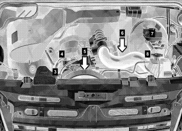
Legend For Instruments And Controls 1. Left-hand air vent. 2. Multifunction switch. 3. Speed control. 4. Hood release lever. 5.
Instrument cluster, refer to "Instrument Cluster and Indicator Lamps".
6. Hazard warning flasher switch. 7. Steering wheel with horn, front driver airbag. 8. Fuse box. 9. Windshield wiper switch, refer to "Windshield
Wiper Switch".
10. Ignition lock/starter switch. 11. Center air vents. 12. Upper air vents. 13. Radio, see individual manual.
14. Temperature control switch. 15. Airflow control switch. 16. Air distribution switch. 17. Temperature sensor, automatic heating
control/air conditioning, regulated.
18. Air conditioning switch. 19. Heater booster switch. 20. Residual engine heat utilization switch. 21. Gear selector lever (automatic transmission) 22. Timer for auxiliary heater. 23. Electrical outlet. 24. Ashtray. 25. Cup holder. 26. Front passenger airbag. 27. Right-hand air vent. 28. Glove compartment. NOTE: For layout of switches, see previous page.
INSTRUMENT CLUSTER AND INDICATOR LAMPS
UNDERSTANDING YOUR INSTRUMENT PANEL 93
94 UNDERSTANDING YOUR INSTRUMENT PANEL
Legend For Instrument Cluster And Indicator Lamps 1. Tachometer (Engine rpm), refer to "Tachometer
(Engine rpm)". 2. Turn signal
indicator
3. Turn signal
"Multifunction Switch". indicator "Multifunction switch".
lamp
(left), refer
to
lamp (right), refer to
4. ASR warning lamp or ESP®* warning lamp. 5. Speedometer. 6. Multi-function indicator, refer to "Multi-Function
Indicator".
7. Gear selector lever position. 8. Coolant temperature gauge, refer to "Coolant
Temperature Gauge". * 2500 Type vehicles only
9. Fuel gauge with reserve fuel indicator lamp (yellow), refer to "Fuel Gauge with Reserve Fuel Indicator Lamp".
10. Warning and indicator lamps. 11. Odometer/trip meter selector, refer to "Odometer
and Trip Meter". Clock/outside temperature display selector, refer to "Clock and Outside Temperature Display".
12. Instrument lighting brighter/dimmer, refer to
"Instrument Lighting".
Indicator Lamp Symbols v Acceleration skid control (ASR)
or electronic stability program (ESP®)* or slippery surface warning.
1 Airbag Malfunction (USA only).
Parking brake applied.
A High beam on, refer to "Multifunction Switch". # Battery not being charged,
refer to "Battery Charge Indicator Lamp". Water in fuel filter, refer to "Water in Fuel Indicator Lamp". 2 Brake pads worn. : Engine oil level too low,
refer to "Engine Oil Level Indicator Lamp".
/ Coolant level too low,
refer to "Coolant Level Indicator Lamp".
; Brake fluid level too low and electronic brake force
distribution (EBD) malfunction (USA only).
*2500 Type Vehicles only.
UNDERSTANDING YOUR INSTRUMENT PANEL 95
3 Brake fluid level too low and electronic brake force
distribution (EBD) malfunction (Canada only).
< Seat belt warning lamp. - Anti-lock brake system (ABS) malfunction. # Electronic stability program (ESP®)* malfunction.
± Engine control unit malfunction.
k Acceleration skid control (ASR) malfunction and brake assist system (BAS)1 malfunction.
™ Constant RPMs on. W Fluid level in windshield washer low. q Preheating.
96 UNDERSTANDING YOUR INSTRUMENT PANEL
Multi-Function Indicator
WARNING!
Never operate buttons (1, 2, 3 and 4) in the multi- function indicator while driving. To operate these buttons the driver must reach through the steering wheel, which could significantly impede its movement. Your attention will also be diverted from the road and traffic conditions. This could cause you to lose control of the vehicle and could lead to an accident and result in severe personal injuries or death. For this reason, make sure that the traffic conditions are safe before pressing the buttons, so that nobody may be endangered. When possible, reach around the steering wheel to operate the multi-function indicator buttons. Do not rest your head or chest on the steering wheel or dashboard when operating the buttons.
The multi-function indicator can be used to call up the odometer, trip meter, clock and outside temperature, or information such as remaining time/distance until the next service is due, or the engine oil level. If your vehicle is equipped with reversing aid, the multi-function indicator also displays the distance between your vehicle and a detected obstacle. The multi-function indicator is activated by: Turning the key to position 2 in the ignition lock, opening the driver’s door, pressing one of the buttons æ, switching the side lights on, refer to "Combination Switch".
(‘), I, ç or
UNDERSTANDING YOUR INSTRUMENT PANEL 97
1. Press the button
(‘) to switch between the odometer and the trip meter, and to reset the trip meter. Press the button maintenance computer.
(‘) to activate the ASSYST
2. Press the I button to switch between the time and outside temperature and to activate the time adjustment.
3. Press the ç to adjust (dim) the display and
instrument lighting and to adjust the clock.
4. Press the æ to adjust (brighten) the display and
instrument lighting and to adjust the clock.
98 UNDERSTANDING YOUR INSTRUMENT PANEL
Clock
Activate the multi-function indicator, refer to "Multi- Function Indicator". Button I – to reverse the time adjustment/ switch between hours and minutes (1) Button ç – to turn the time back (2) Button æ – to advance the time (3)
To switch between Time and Outside Temperature Display (Optional) Press the I button briefly.
If button I is pressed twice within one second, the display will revert to the original mode after 20 seconds.
To Adjust the Time Call up time display: 1. Press button I and hold – the hours display will
flash. To change the time by one hour = briefly press button æ or ç. To change the time by several hours = press and hold button æ or ç.
2. Briefly press button I – the minutes display will
flash. To change the time by one minute = briefly press button æ or ç. To change the time by several minutes = press and hold button æ or ç.
3. Briefly press button I – the set time is accepted.
Odometer and Trip Meter
Instrument and Display Lighting
UNDERSTANDING YOUR INSTRUMENT PANEL 99
Display lighting: 3. Press button ç, to display lighting dimmer 4. Press button æ, to display lighting brighter
the multi-function
Activate distance covered by the vehicle will be shown. 1. To switch between the odometer and the trip meter,
indicator. The
total
press button (1) briefly.
2. To reset the trip meter, call up trip meter. Press button (1) and hold until the trip meter shows 0000.
NOTE: Odometer and trip meter display – "mi" in USA only. – "km" in Canada only.
100 UNDERSTANDING YOUR INSTRUMENT PANEL
Instrument and display lighting: 1. Switch on the marker lamps, refer to "Combination
Switch"
2. Press button ç, to make instrument and display
lighting dimmer
3. Press button æ, to make instrument display
lighting brighter
Outside Temperature Display
Clock/outside temperature display selector (1) Press button I briefly. The display will switch to the required mode. If button I is pressed twice within one second, the display will revert to the original mode after 20 seconds.
The outside temperature is displayed when the multi- function indicator is activated. Sudden changes in temperature, for instance when leaving a garage, are only shown after a certain delay. NOTE: Outside temperature display °F in USA only. °C in Canada only.
WARNING!
Even if the display still reads a few degrees above 32°F (0°C), the road surface may be icy, particular- ly in woods or on bridges. You could skid and lose control over your vehicle and thereby cause an ac- cident. Adapt your speed and driving style to the prevailing road and weather conditions to prevent an accident and possible personal injury or property damage.
UNDERSTANDING YOUR INSTRUMENT PANEL 101
in
Reversing Aid Distance Display (Optional) When the key is in position 2 in the ignition lock and the reverse gear is engaged, the reversing aid automatically begins to monitor the area to the rear of the vehicle.
102 UNDERSTANDING YOUR INSTRUMENT PANEL
The following display appears if the reversing aid does not detect an obstacle.
When a continuous warning signal sounds for approximately three seconds and the error code
NOTE: Distance display (cid:127) "in" in USA only. (cid:127) "cm" in Canada only. The distance between the sensors and an obstacle detected within the monitoring range is displayed in increments of 2 in (5 cm). If the distance is less than 40 in (100 cm), a warning signal also sounds, which is repeated increasingly frequently as the vehicle approaches the obstacle. A continuous warning signal sounds if the distance undershoots 20 in (50 cm).
appears in the multi-function indicator, the reversing aid is malfunctioning. Maneuver with particular care, if interference from an external source of ultrasonic waves (compressed-air brakes of trucks, a car wash or a pneumatic drill) is causing the reversing aid to malfunction. Dirty reversing aid sensors or malfunctioning backup lamps could also cause to malfunction. Clean the reversing aid sensors and check the backup lamps. Otherwise have the malfunction traced and rectified by an authorized Sprinter Dealer.
the reversing aid
Tachometer (Engine rpm)
Coolant Temperature Gauge
UNDERSTANDING YOUR INSTRUMENT PANEL 103
Do not exceed the maximum permissible engine speed. NOTE: To protect the engine, its fuel supply is interrupted when the maximum rpm is reached. Despite this, the maximum rpm can still be exceeded in overrun mode (e.g. when driving downhill).
The coolant temperature is displayed when the key is in position 2 in the ignition lock. If corrosion inhibitor/antifreeze is present in the correct concentration in the coolant, the coolant temperature will be between 185 °F (+85 °C) and 250 °F (+120 °C), depending on operating conditions. If the needle reaches the red section, do not continue to drive the vehicle.
104 UNDERSTANDING YOUR INSTRUMENT PANEL
CAUTION!
Do not leave your vehicle unattended with the engine running as you would not be able to react to the temperature indicator if the engine overheats. This would lead in turn to engine damage.
For coolant level indicator lamp /, refer to "Coolant Level Indicator Lamp". NOTE: Coolant temperature display °F in USA only. °C in Canada only.
WARNING!
Driving when your engine is badly overheated can cause some fluids which may have leaked into the engine compartment to catch fire. You could be seriously burned. Steam from an overheated engine can cause serious burns and can occur just by opening the engine hood. Stay away from the engine if you see or hear steam coming from it. Turn off the engine, get out of the vehicle and do not stand near the vehicle until it cools down.
Fuel Gauge with Reserve Fuel Indicator Lamp
The fuel level is displayed when the key is in position 2 in the ignition lock.
UNDERSTANDING YOUR INSTRUMENT PANEL 105
The reserve fuel indicator lamp (1) lights up for about 2 seconds. If the reserve fuel indicator lamp remains on or lights up again when the engine is running, the fuel in the tank hasreached reserve level. Reserve level: about 2.8 US gal (10.5 liters). NOTE: If the fuel gauge sensor is damaged, the reserve fuel indictor lamp (1) will light up and the needle will vary its position between the maximum and minimum marks. Have the malfunction traced and rectified by an authorized Sprinter Dealer.
106 UNDERSTANDING YOUR INSTRUMENT PANEL
Battery Charge Indicator Lamp
Water in Fuel Indicator Lamp
When the key is in position 2 in the ignition lock, the battery charge indicator lamp # will light up in the instrument cluster. It must go out when the engine is running. If the battery charge indicator lamp # remains on or lights up again while the vehicle is moving, a fault has developed in the battery charge circuit. Do not drive on. Take your vehicle to an authorized Sprinter Dealer to have the problem corrected.
indicator
When the key is turned to position 2 in the ignition lock, the fuel filter in the instrument cluster lights up for about 2 seconds. It must go out when the engine is running. If water in fuel indicator lamp does not go out or comes on with the engine running, drain the water from the fuel filter as soon as possible.
lamp
NOTE: Should the water in fuel indicator lamp still not go out after the fuel filter has been drained, the cause should be examined by an authorized Sprinter Dealer. does not light up for about If the indicator lamp 2 seconds with the key in the ignition lock in position 2, there is a malfunction in the water separator system. Have the cause rectified by an authorized Sprinter Dealer.
UNDERSTANDING YOUR INSTRUMENT PANEL 107
Engine Oil Level Indicator Lamp
The engine oil level indicator lamp : lights up in the instrument cluster when the key is turned to position 2 in the ignition lock. It must go out when the engine is running.
108 UNDERSTANDING YOUR INSTRUMENT PANEL
If the engine oil level indicator lamp : does not go out, or if it lights up again while the vehicle is moving, the engine oil level has dropped to a point close to the minimum level mark on the dipstick. The indicator lamp : lights up only briefly at first, becoming permanent as the oil level drops further. Stop the engine immediately and check the engine oil level. If no obvious leak is visible, correct the oil level. If the engine oil level indicator lamp : lights up, even if the engine oil level is sufficient, have the cause traced and rectified by an authorized Sprinter Dealer. For approved engine oils, please contact your authorized Sprinter Dealer.
Coolant Level Indicator Lamp
When the key is turned to position 2 in the ignition lock, the coolant level indicator lamp / in the instrument cluster lights up for about 2 seconds. It must go out when the engine is running. If the coolant level indicator lamp / remains on or lights up again when the engine is running, the coolant level is too low. Do not drive on. Switch the engine off and add coolant.
If a large quantity of coolant is being lost, or if smaller amounts are lost at regular intervals, have the engine cooling system examined by an authorized Sprinter Dealer.
CAUTION!
Never run the engine if the coolant level is too low. This could cause the engine to overheat, leading in turn to engine damage.
WARNING!
Driving when your engine is badly overheated can cause some fluids which may have leaked into the engine compartment to catch fire. You could be seriously burned. Steam from an overheated engine can cause serious burns and can occur just by opening the engine hood. Stay away from the engine if you see or hear steam coming from it. Turn off the engine, get out of the vehicle and do not stand near the vehicle until it cool downs.
UNDERSTANDING YOUR INSTRUMENT PANEL 109
Engine Control Unit Indicator Lamp
When the key is in position 2 in the ignition lock, the engine control unit indicator lamp ± will light up in the instrument cluster. It must go out when the engine is running. If the engine control unit indicator lamp± remains on or lights up again while the vehicle is moving, the fuel tank was run empty or a fault has developed in the engine control unit. The engine’s power output may be reduced. Refuel and bleed the fuel system or have the cause traced and rectified by an authorized Sprinter Dealer.
110 UNDERSTANDING YOUR INSTRUMENT PANEL
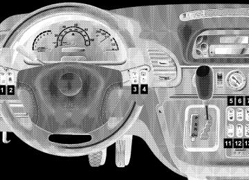
SWITCH LOCATIONS
Legend for Switch Locations 1. Fog lamp switch (Optional), refer to "Fog Lamp
Switch".
2. Headlamp range control, refer to "Headlamp
Range Control".
3. Auxiliary heat exchanger switch (Optional). 4. Heated rear window (Optional). 5. Left-hand seat heater switch (Optional). 6. Central locking switch with load compartment lock
(Optional).
7. Alarm pushbutton. 8. Deactivate Acceleration skid control (ASR) switch.
UNDERSTANDING YOUR INSTRUMENT PANEL 111
9. Switch for auxiliary heater (Optional) 10. Right-hand seat heater switch (Optional), 11. Sun roof operation switch (Optional). 12. Interior cargo area lighting (Optional), refer to "Interior Cargo Area Lighting".
13. Towing/passenger compartment protection switch
(Optional).
14. Airflow switch for the air conditioner for rear
passenger compartment (Optional).
15. Temperature control (Optional). 16. Electric blower switch (Optional). 17. Windshield heater switch (Optional). 18. Constant RPM switch (Optional).
112 UNDERSTANDING YOUR INSTRUMENT PANEL
ASSYST MAINTENANCE COMPUTER (OPTIONAL)
If additional maintenance operations are due, the maintenance indicator
Symb N00.00-2388-00
or
Symb N00.00-2157-00
lights up when the key is turned to position 2 in the ignition lock. For additional maintenance operations, see Sprinter Service Booklet. If a service deadline is exceeded, the display will flash with a minus sign in front when the key is turned to position 2 in the ignition lock. The display will button 10 seconds. The remaining time or remaining distance can also be called up manually. To manually call up the remaining time/distance: Activate the multi-function indicator, refer to "Multi- Function Indicator". Briefly press the button
the (‘) is pressed, or automatically after
cancelled when
(‘) twice.
be
Function button Approximately one month or 2,000 miles (3,000 km) before a service is due, the maintenance symbol
(‘) (1)
Symb N00.00-2387-00
or
Symb N00.00-2156-00
lights up when the key is turned to position 2 in the ignition lock. If the remaining time (in days) is shown, the additional symbol È also appears in the multi-function indicator.
be
the (‘) is pressed, or automatically after
Depending on the driving style, the mileage covered and the operating conditions, the next service due is displayed either as a remaining distance in "mi" (in km) or as a remaining time in "days". The length of time between services should not exceed 2 years. The display will cancelled when button 10 seconds. When a service has been performed, have the ASSYST maintenance computer reset by an authorized Sprinter Dealer. Should your Sprinter for any reason not be serviced by an the ASSYST maintenance exceptional can, circumstances, be reset as follows: Turn the key to position 2 in the ignition lock and immediately press the button Within 10 seconds, return the key to position 0 in the ignition lock. Press and hold the button position 2 button
(‘). Turn the key to the
authorized Sprinter Dealer,
in (‘) pressed.
lock. Keep
(‘) twice.
computer
ignition
the
in
UNDERSTANDING YOUR INSTRUMENT PANEL 113
The maintenance indicator with the current remaining time/distance is shown. After about 10 seconds, an acoustic signal will sound and the maintenance indicator is displayed with the new remaining time/distance. Release the button (‘). NOTE: The ASSYST maintenance computer provides information on the optimum maintenance requirements. If maintenance intervals are not observed, resulting damage will not be covered by Warranty. The ASSYST maintenance computer is not an engine oil gauge. Engine oil level – for display in instrument cluster, see next page. If the engine oil level indicator lamp lights up, refer to "Engine Oil Level Indicator Lamp". If the battery is disconnected, the time is not recorded by the ASSYST maintenance computer. Such periods must be considered if maintenance intervals are measured by time.
114 UNDERSTANDING YOUR INSTRUMENT PANEL
Engine Oil Level – Display in Instrument Cluster (Vehicles with ASSYST Maintenance Computer only)
If no engine oil is added and the engine oil level drops further, a warning buzzer will also sound and
Symb N00.00-2384-00
qt
will appear in the multi-function indicator. 2.0 quarts (about 1.9 liters) of oil must be added. NOTE: Engine oil level display – "qt" in USA only. – "l" in Canada only.
CAUTION!
If the : indicator lamp lights up, the warning symbol in the multi-function indicator appears and the warning buzzer sounds, the operating safety of the engine is endangered (possibility of engine damage). A sudden decrease or absence of oil pressure may indicate a mechanical failure. Bring the vehicle to a safe stop, and investigate the cause to prevent further damage. Do not operate the engine until the cause has been determined and corrected.
If the : indicator lamp lights up briefly when the engine is running, the engine oil level has dropped to the minimum mark. Check the engine oil level without delay and add oil to the upper mark on the dipstick.
If the warning
Symb N00.00-2150-00
is displayed in the multi-function indicator while the engine is running, the engine oil level is above maximum.
CAUTION!
Do not operate the engine if the oil level is above maximum. There is a danger of damage to the engine or catalytic converter.
Siphon or drain off engine oil until the engine oil level is between the lower and upper marks on the dipstick. Check the engine oil level again.
Symb N00.00-2151-00
must be displayed. NOTE: If the oil level is correct and a fault warning is still given, have the fault traced and rectified by an authorized Sprinter Dealer.UNDERSTANDING YOUR INSTRUMENT PANEL 115
Displaying Engine Oil Level with Engine Off
the engine has
If reached normal operating temperature, the engine oil level can be displayed on the multi-function indicator for about 5 minutes after the engine has been switched off. The vehicle must be standing on a level surface when the engine oil is being checked. Turn the key to position 2 in the ignition lock and wait about 10 seconds until the multi-function indicator shows the : symbol.
116 UNDERSTANDING YOUR INSTRUMENT PANEL
Briefly press button (1) twice within 1 second. The following displays can then appear in the multi- function indicator:
Symb N00.00-2151-00
Symb N00.00-2385-00
qt
Symb N00.00-2386-00
qt
It is not necessary to add engine oil.
1 quart (about 1 liter) of engine oil must be added.
1.5 quarts (about 1.4 liters) of engine oil must be added.
Symb N00.00-2384-00
qt
2 quarts (about 1.9 liters) of engine oil must be added.
Excess engine oil must be drained or siphoned off.
NOTE: Engine oil level display – "qt" in USA only. – "l" in Canada only.
CAUTION!
If the engine oil level is too high or too low the engine can be damaged. Add engine oil or siphon or drain off engine oil until the engine oil level is between the lower and upper marks on the dipstick. Only add engine oil up to the upper mark-do not overfill. If the engine oil level is above maximum, there is a danger of damage to the engine or catalytic converter.
NOTE: If the engine oil level is correct and a warning that the engine oil level is too high or too low is still given, have the fault traced and rectified by an authorized Sprinter Dealer. If it is not possible to measure the engine oil level correctly, the È symbol will flash in the multi- function indicator – repeat the measurement after waiting a short time. If no engine oil level reading is shown again, the engine oil level can still be checked with the dipstick. Consult an authorized Sprinter Dealer to have the system checked.
UNDERSTANDING YOUR INSTRUMENT PANEL 117
CAUTION!
If the : indicator lamp lights up, the warning symbol in the multi-function indicator appears and the warning buzzer sounds, the operating safety of the engine is endangered (possibility of engine damage). Safely pull off the road and turn off the engine (do not restart the engine). Determine the cause of the problem. If there are no obvious signs of leakage, add engine oil. The engine oil level must be between the lower and upper marks on the dipstick. Only add engine oil up to the upper mark – do not overfill. If the engine oil level is above maximum, there is a danger of damage to the engine or catalytic converter.
ENGINE OIL LEVEL INDICATOR IN INSTRUMENT CLUSTER (VEHICLES WITHOUT ASSYST MAINTENANCE COMPUTER) If the : indicator lamp lights up when the engine is running, the engine oil level has dropped to the minimum mark. Check the engine oil level without delay and add engine oil up to the upper mark on the dipstick. If there is no engine oil in the oil sump, a warning buzzer will sound if the key is turned to position 2 in the ignition lock or if the vehicle is being driven, and the warning
Symb N00.00-2384-00
qt
will appear in the multi-function indicator. About 2
quarts (1.9 liters) of oil must be added. Check the engine oil level without delay and add engine oil to the upper mark on the dipstick. NOTE: Engine oil level display (cid:127) "qt" in USA only. (cid:127) "l" in Canada only.118 UNDERSTANDING YOUR INSTRUMENT PANEL
HEATING, VENTILATION
Temperature control (1) Airflow control (2) Air distribution control (3)
Z Air to the windshield and from the air vents X Air to the windshield and footwell and from
the air vents
Y Air to the footwell and from the air vents h Air from the air vents
NOTE: If the vehicle interior has been heated up by intense sunlight, ventilate the interior briefly before driving the vehicle. Only with automatic heater control (Optional): The selected temperature is reached as quickly as possible in heater mode and then held constant.
WARNING!
Follow the recommended settings for heating and cooling given on the following pages. Otherwise the windows could fog up, impairing visibility and endangering you and others.
Ventilation
Air Recirculation
UNDERSTANDING YOUR INSTRUMENT PANEL 119
1. Set the airflow control (2) to position 3 or 4. 2. Set the temperature control (1) as illustrated (heater
switched off).
3. Set the air distribution control (3) to h. NOTE: Adjust the air vents as required, refer to "Side Air Vents and Center Air Vents".
Air recirculation indicator lamp (1) Air recirculation button (2) To switch on air recirculation: (cid:127) Press the air recirculation button – the indicator
lamp lights up.
To switch off air recirculation: (cid:127) Press the air rescirculation button again – the
indicator lamp goes out.
120 UNDERSTANDING YOUR INSTRUMENT PANEL
Select air recirculation if dust or unpleasant odors enter the vehicle. NOTE: Prolonged air recirculation can worsen the air quality and lead to fogging up of the windows. Shut off air recirculation as soon as possible. Only with automatic heat regulation and regulated air conditioning (Optional): Air recirculation is automatically switched off after about 15 minutes or when engine is shut off.
Heating
1. Set the airflow control (2) as required. 2. Set the temperature control (1) as required. 3. Set the air distribution control (3) between Y
and X.
4. Switch off air
Recirculation".
recirculation,
refer
to
"Air
5. Adjust the air vents as required, refer to "Side Air
Vents and Center Air Vents".
UNDERSTANDING YOUR INSTRUMENT PANEL 121
to
in
the
"Auxiliary Heat Exchanger
NOTE: On vehicles with auxiliary heater (water heater): The additional heat exchanger load compartment should be switched off to quickly de-fog and de-ice the windshield and front side windows, refer in Load Compartment". For how to switch on heater booster mode, refer to "Heater Booster". On vehicles with air conditioner (Optional): At outside temperatures above 41 °F (+5 °C), switch on the air conditioner for quicker dehumidification, refer to "Air Conditioning, Regulated".
De-Fogging and De-Icing The Front Windows
1. Set the airflow control (2) to position 3 or 4. 2. Set the temperature control (1)
to P.
3. Set the air distribution control (3) to Z. refer 4. Switch off air
recirculation,
Recirculation".
to
"Air
122 UNDERSTANDING YOUR INSTRUMENT PANEL
Side Air Vents and Center Air Vents
Upper Air Vents
To open, turn the thumbwheel outwards. To close, turn the thumbwheel inwards. Intermediate settings are possible.
The upper air vents supply fresh air (not heated) to the passenger/load compartment. To open, turn the thumbwheel forwards. To close, turn the thumbwheel rearwards.
Heated Rear Window (Optional)
Windshield Heater (Optional)
UNDERSTANDING YOUR INSTRUMENT PANEL 123
The switch for the heated rear window is located on the right-hand side next to the steering column. It can be used only when the engine is running.
The switch for the windshield heater is located on the center section of the dashboard. It can be used only when the engine is running.
To switch it on: (cid:127) Press upward; the indicator lamp in the switch will
light up.
To switch off: (cid:127) Press upward one more time. NOTE: The heated rear window will automatically switch off after about 15 minutes or when the engine is turned off.
To switch it on: (cid:127) Press upward; the indicator lamp in the switch will
light up.
To switch off: (cid:127) Press upward one more time. NOTE: The windshield heater will automatically switch off after about 5 minutes or when the engine is turned off.
124 UNDERSTANDING YOUR INSTRUMENT PANEL
Residual Engine Heat Utilization (REST)
The REST switch (1) is located on the center section of the dashboard. The residual engine heat utilization system can be used to keep the vehicle interior warm for some time after the engine is switched off.
Turn the key to position 0 in the ignition lock or remove it altogether. To switch on: 1. Press the residual engine heat utilization switch (1),
the indicator lamp (2) lights up. The blower will run at speed 1 regardless of the setting of the airflow control.
2. Set the temperature control as required, refer to
"Heating, Ventilation".
To switch off: Press the residual engine heat utilization switch (1) again, the indicator lamp (2) goes out.
the key is turned to position 2 in the ignition lock,
The residual engine heat utilization is automatically switched off if: 1. 2. after about 30 minutes, 3. AIR CONDITIONING, REGULATED (OPTIONAL)
if the battery voltage is too low.
The air conditioning switch (1) is located on the center section of the dashboard. The air conditioning can be used to cool or dehumidify the air in the vehicle. The selected temperature is reached as quickly as possible and then held constant.
The air conditioning is only operational when the engine is running.
To switch on: Press switch (1), the indicator lamp (2) in the switch lights up. To switch off: Press switch (1) again, the indicator lamp (2) goes out. NOTE: Run the air conditioning at least once a month for about 10 minutes. It the air conditioning will automatically switch off at outside temperatures below 41 °F (+5 °C). Dehumidification is then also not possible. Condensation may emerge from the underside of the vehicle. The air conditioner only uses the refrigerant R-134a. This refrigerant does not damage the earth’s ozone layer.
is possible
that
WARNING!
UNDERSTANDING YOUR INSTRUMENT PANEL 125
Climate Control (on Vehicles with Air Conditioning)
1. Set the airflow control (2) to position 1 to 4.
Position 4 gives maximum cooling.
temperature
2. Set the temperature switch (1) as required (The interior the Tempmatik. If the interior temperature falls below the preset temperature, warm air is automatically supplied).
regulated by
is
While driving, deactivate the air conditioning only temporarily to prevent window fogging.
3. Set the air distribution control (3) to h. 4. To switch on air conditioning, press switch (4).
126 UNDERSTANDING YOUR INSTRUMENT PANEL
NOTE: Open and adjust the air vents as required, refer to "Side Air Vents and Center Air Vents". At high outside temperatures, a better cooling performance is achieved by switching on air recirculation. For note on air recirculation, refer to "Air Recirculation".
Dehumidification (on Vehicles with Air Conditioning)
1. Set the airflow control (2) to position 3 or 4. 2. Set the temperature control (1) as required. 3. Set the air distribution control (3) between X
and Z.
NOTE: It is possible that the air conditioning will automatically switch off at outside temperatures below 41 °F (+5 °C). Dehumidification is then also not possible. To switch on air conditioner, press switch (4). Open the side air vents as required, refer to "Side Air Vents and Center Air Vents". Air Conditioner for the Rear Passenger Compartment (Optional)
The air conditioner for the rear passenger compartment must be used in conjunction with “Air Conditioning, Regulated”, refer to “Air Conditioning, Regulated”.
UNDERSTANDING YOUR INSTRUMENT PANEL 127
1. Air conditioning, regulated switch 2. Air conditioning,
regulated indicator lamp 3. Airflow switch 4. Temperature
control
128 UNDERSTANDING YOUR INSTRUMENT PANEL
To switch it on: 1. Press switch (1) on air conditioning, regulated.
The indicator lamp (2) will light up.
2. Operate the airflow switch (3).
level 1, press
the airflow switch (3) Blower upwards; the left-hand indicator lamp will light up. Blower the airflow switch (3) downwards; the right-hand indicator lamp will light up.
level 2, press
3. Set temperature control (4) as needed.
Increase cooling turn upwards. Decrease cooling turn downwards.
To switch off: 1. Switch the airflow switch (3) to the center position. 2. Press switch (1) air conditioning, regulated; the
indicator lamp (2) will go out.
Air Recirculation Recirculation mode can now be assisted by the air conditioner for rear passenger compartment. To switch it on: Operate the airflow switch (3) Blower level 1, press the airflow switch (3) upwards; the left-hand indicator lamp will light up. Blower switch (3) airflow downwards; the right-hand indicator lamp will light up. To switch off: Switch the airflow switch (3) to the center position.
level 2, press
the
Air Strainer
Removing and Cleaning the Air strainer
UNDERSTANDING YOUR INSTRUMENT PANEL 129
To lock fasteners (1) To unlock fasteners (2) The air strainer is located at the rear of the air conditioner for rear passenger compartment. Increased quantities of sand or dust may settle on the air conditioner for rear passenger compartment air strainer when driving on dusty or sandy streets. The air strainer must be either cleaned or replaced in the event of visible contamination.
1. Unlock all quick-acting fasteners (2). 2. Remove the cover and air strainer (3). 3. Remove the Velcro closure (4) from the cover (6)
and the grating (5).
4. Remove the air strainer (3) from the grating. 5. Wash out the air strainer (3) with clean water. 6. Let the air strainer (3) dry. NOTE: The air strainer (3) must not be cleaned or dried by machine.
130 UNDERSTANDING YOUR INSTRUMENT PANEL
Installing the Air Strainer 1. Affix the air strainer (3) to the grating (5) (make
certain that the ends project evenly).
2. Replace the air strainer (3) and grating (5) on the cover and press the Velcro closure (4) on the cover (6). Insert the air strainer (3) with the cover and grating (5).
3.
4. Lock (1) all quick-acting fasteners.
CAUTION!
Never operate the air conditioner for rear passenger compartment without an air strainer. Never install a damaged air strainer. If the air strainer with visible contamination is neither cleaned nor replaced, damage to the air conditioner for rear passenger compartment may result; such damage is not covered by the Warranty.
ELECTRIC BLOWER (OPTIONAL) See Section 4, Understanding Your Instrument Panel, for switch locations.
The electric blower can be used to aerate or deaerate the cargo area. This feeds fresh air into the cargo area or extracts warm air.
Deaeration: Press switch upward. Aeration: Press switch downward. To switch off: Switch the airflow switch to the center position.
HEATER BOOSTER
The switch (1) for activating the heater booster system is located in the center section of the dashboard. The heater booster system can be switched on while the vehicle is being driven to help the engine to reach operating temperature more quickly, which will help to heat up the passenger compartment as quickly as possible when the heating is switched on.
normal
its
UNDERSTANDING YOUR INSTRUMENT PANEL 131
To switch on with the engine running: Press switch (1), the indicator lamp (2) lights up. To switch off: Press switch (1) again or switch the engine off. The heater booster will then switch to run-on mode (about 2 minutes). NOTE: When the vehicle is being driven and a coolant temperature of over 185 °F (+80 °C) is reached, the heater booster system will switch to regulation mode. If the coolant temperature drops to below 167 °F (+75 °C) with the heater booster system switched on, heat output is increased again. If the key is turned to position 0 in the ignition lock (run-on for about 2 minutes), the last setting selected at switch (1) is retained when the engine is restarted (memory function). The operation of the heater booster system is usually not required at outside temperatures above 41 °F (+5 °C).
132 UNDERSTANDING YOUR INSTRUMENT PANEL
AUXILIARY HEATER – WATER OR AIR HEATER (OPTIONAL)
WARNING!
The auxiliary heating must not be operated at gas stations due to the risk of fire and explosion. For this reason, switch off the auxiliary heating before refuelling. Auxiliary heaters emit fumes when in operation, including carbon monoxide. Inhaling carbon monoxide is a health hazard and can result in unconsciousness and death. For this reason, do not operate auxiliary heating in enclosed spaces without ventilation or an extractor system, e.g. in a garage. Otherwise you could endanger yourself and others. Always keep the ground under the vehicle as clear as possible so that the auxiliary heater can receive enough combustion air and exhaust fumes can escape. Otherwise you could endanger yourself and others.
WARNING!
Vehicles for transporting hazardous goods: Observe the relevant safety regulations.
NOTE: The auxiliary heater (water or air heating device) can be used whether or not the engine is running. After you have filled your vehicle’s gas tank with winterized diesel fuel for the first time, is recommended that you operate the auxiliary heater before beginning a journey or operating the heater continuously so that any summer diesel fuel left in the auxiliary heater can combust. Before switching the auxiliary heater on make sure that that the battery is sufficiently charged and that there is enough fuel in the tank. At least a quarter of the tank should be filled up. See Fuel Gauge.
it
NOTE: After three successive attempts to start the heater, a malfunction will be recorded in the integrated diagnostic system and no further operation on auxiliary heater will be available (lock-out). The work to annul the lock-out must be carried out at an authorized Sprinter Dealer. The auxiliary heater should be run at least once a month for about 10 minutes. The maximum heating period is 120 minutes. For more information, refer to "Switching the Auxiliary Heater On and Off - Ignition On". The auxiliary heater will automatically switch off if the fuel level is under about 4 US gal (15 l). In case of faults, refer to "Auxiliary Heater – Tips for Coping with Problems".
UNDERSTANDING YOUR INSTRUMENT PANEL 133
WARNING!
Aerosals, gas cartridges and other pressurized containers transported in the vehicle may be high- ly flammable and could explode when heated. Make sure, particularly on vehicles with an air heater, that such containers are not placed in the flow of hot air of the auxiliary heating system Otherwise there is a risk of severe personal injuries, death and property damage due to explosion.
WARNING!
Vehicles with air heater: For safety reasons, we strongly recommend that the heat exchanger be replaced by an authorized Sprinter Dealer after 10 years of use. If the vehicle is sold, the owner is required to inform the buyer of this requirement. This should be done when is transferred to the buyer.
the Operator’s Manual
134 UNDERSTANDING YOUR INSTRUMENT PANEL
Auxiliary Heater Switch
Timer Auxiliary Heater
To switch it on: Press the switch upward. The indicator lamp in the switch will light up. The will automatically switch off after about 120 minutes. The auxiliary heater will switch over to after-running mode (about 2 minutes). To switch off: Press the switch downward. The indicator lamp in the switch will go out.
auxiliary
heater
NOTE: The timer water heater has no adjustable temperature selection transformer (10). Memory location (1 – 3) (1) Current day or preselected day (2) Current time or preselected time (3) Symbol ö – Status display (4) Button ” – Set time and day (5)
Button H – Select memory (1 – 3), activate preselected time (6) Button ö – Switch on heater (7) Button ý – Set time, day, and preselected time; shorten heating period (min. 1 minute) (8) Button þ – Set time, day, and preselected time; lengthen heating period (max. 120 minutes) (9) Air Heater only, adjustable temperature selection transformer – adjustment range from 50 °F to 86 °F (+10 °C to +30 °C) (10) NOTE: All symbols and digits in the display will flash if the battery voltage has been interrupted over a longer period of time. The timer must be reset. The heater cannot be switched on until the time of day has been set. The timer lights up when the heater is switched on.
UNDERSTANDING YOUR INSTRUMENT PANEL 135
Switching the Auxiliary Heater On and Off - Ignition Off To switch it on: Press button ö. The vehicle-side blower automatically switches on. Display: Symbol ö and remaining heating period. The remaining heating period can be lengthened by using the button þ (max. of 120 minutes); it may be shortened by using the button ý (min. of 1 minute). To switch off: Press button ö again. The blower inside the vehicle automatically switches off. The auxiliary heater will automatically switch off after about 3 minutes. Display: Current time and current day of the week (about 15 seconds). Switching the Auxiliary Heater On and Off - Ignition On To switch it on: Press the button ö.
136 UNDERSTANDING YOUR INSTRUMENT PANEL
The auxiliary heater is running. Display: Symbol ö, current time and current day of the week. If the ignition is switched off, the auxiliary heater will remain on for another 15 minutes before automatically switching off. The remaining heating period can be lengthened by using the button þ (max. of 120 minutes); it may be shortened by using the button ý (min. of 1 minute). To switch off: Press the button ö again. The auxiliary heater will automatically switch off after about 3 minutes. Display: Current time and current day of the week. Setting the time and day Press the button ” until the "Time" display begins to flash. Use either the button ý or þ to set the current time. The current time has been saved when the display stops flashing or the button ” is used for confirmation.