- Download PDF Manual
-
lower control arm as shown below.
WHAT TO DO IN EMERGENCIES 425
1500 4X2 Jacking Location
426 WHAT TO DO IN EMERGENCIES
1500 4X4 Jacking Location
† For 2500/3500 4x2 series trucks, when changing a front wheel, place the bottle jack under the frame rail behind the wheel. Locate the jack as far forward as possible on the straight part of the frame.
4X2 Jacking
† Operate the jack using the jack drive tube and the wheel wrench. The tube extension, may be used, but is not required.
† For 2500/3500 4x4 series trucks, when changing the front wheel, assemble the jack drive tube to the jack and connect the drive tube to the extension tube. Place the jack under the axle as close to the tire as possible with the drive tubes extending to the front. Connect the jack tube extension and wheel wrench.
WHAT TO DO IN EMERGENCIES 427
† For all trucks, when changing a rear wheel, as- semble the jack drive tube to the jack and connect the drive tube to the extension tube. Place the jack under the axle between the spring and the shock absorber with the drive tubes extending to the rear.
Rear Jacking Location (All)
428 WHAT TO DO IN EMERGENCIES
† Connect the jack tube extension and wheel wrench. Before raising the wheel off the ground, make sure that the jack will not damage surrounding truck parts and adjust the jack position as required.
If the 2500/3500 bottle jack will not lower by NOTE: turning the dial (thumbwheel) by hand, it may be neces- sary to use the jack drive tube in order to lower the jack. 4. By rotating the wheel wrench clockwise, raise the vehicle until the wheel just clears the surface.
WARNING!
Raising the vehicle higher than necessary can make the vehicle unstable and cause an accident. It could slip off the jack and hurt someone near it. Raise the vehicle only enough to remove the tire.
5. Remove the wheel nuts and pull the wheel off. Install the spare wheel and wheel nuts with the cone shaped end of the nuts toward the wheel on 1500/2500/3500 single rear-wheel (SRW) models. On 3500 dual rear-wheel mod- els (DRW) the lug nuts are a two-piece assembly with a flat face. Lightly tighten the nuts. To avoid risk of forcing the vehicle off the jack, do not fully tighten the nuts until the vehicle has been lowered. 6. Using the wheel wrench, finish tightening the nuts using a crisscross pattern. Correct nut tightness is 135 ft lbs (183 N·m) torque for 1500/2500/3500 single-rear wheel (SRW) models, and 145 ft lbs (197 N·m) for 3500
dual rear-wheel models. If in doubt about the correct tightness, have them checked with a torque wrench by your authorized dealer or at a service station.WARNING!
A loose tire or jack thrown forward in a collision or hard stop could injure someone in the vehicle. Al- ways stow the jack parts and the extra tire and wheel in the places provided.
7. Install wheel center cap and remove wheel blocks. Do not install chrome or aluminum wheel center caps on the spare wheel. This may result in cap damage. 8. Lower the jack to its fully closed position. If the bottle jack will not lower by turning the dial (thumbwheel) by hand, it may be necessary to use the jack drive tube in order to lower the jack. Stow the replaced tire, jack, and tools as previously described. 9. Adjust the tire pressure when possible.
WHAT TO DO IN EMERGENCIES 429
NOTE: Do not oil wheel studs. For chrome wheels, do not substitute with chrome plated wheel nuts. Hub Caps/Wheel Covers The hub caps must be removed before raising the vehicle off the ground. For 2500/3500 single rear-wheel (SRW) models, use the blade on the end of the lug wrench to pry the hub cap off. Insert the blade end into the pryoff notch and carefully pop off the hub cap with a back-and-forth motion. On 3500 models with dual rear wheels (DRW), you must first remove the hub caps. The jack handle driver has a hook at one end that will fit in the pry off notch of the rear hub caps. Position the hook and pull out on the ratchet firmly. The hub cap should pop off. The wheel skins can now be removed. For the front hub cap on 3500
models use the blade on the end of the lug wrench to pry the caps off. The wheel skin can now be removed.430 WHAT TO DO IN EMERGENCIES
CAUTION!
Use a back-and-forth motion to remove the hub cap. Do not use a twisting motion when removing the hub cap, damage to the hub cap finish may occur.
CAUTION!
The rear hub caps on the dual rear wheel has two pry-off notches. Make sure that the hook of the jack handle driver is located squarely in the cap notch before attempting to pull off.
You must use the flat end of the lug wrench to pry off the wheel skins. Insert the flat tip completely and using a back-and-forth motion, loosen the wheel skin. Repeat this procedure around the tire until the skin pops off. Replace the wheel skins first using a rubber mallet. When replacing the hub caps, tilt the cap retainer over the lugnut bolt circle and strike the high side down with a rubber mallet. Be sure that the hub caps and wheel skins are firmly seated around the wheel.
8-Stud — Dual Rear Wheels Dual wheels are flat-mounted and center-piloted. The lug nuts are a two-piece assembly. When the tires are being rotated or replaced, clean these lug nuts and add two drops of oil at the interface between the hex and the washer.
WHAT TO DO IN EMERGENCIES 431
Slots in the wheels will assist in properly orienting the inner and outer wheels. Align these slots when assem- bling the wheels for best access to the tire valve on the inner wheel. The tires of both dual wheels must be completely off the ground when tightening, to ensure wheel centering and maximum wheel clamping. Dual wheel models require a special heavy-duty lug nut tightening adapter (included with the vehicle) to cor- rectly tighten the lug nuts. Also, when it is necessary to remove and install dual rear wheels, use a proper vehicle lifting device. NOTE: When installing a spare tire as part of a dual rear wheel end combination, the tire diameter of the two individual tires must be compared. If there is a significant difference, the larger tire should be installed in a front location. Correct direction of rotation for dual tire instal- lations must also be observed.
432 WHAT TO DO IN EMERGENCIES
These dual rear wheels should be tightened as follows:
1. Tighten the wheel nuts in the numbered sequence to a snug fit. 2. Retighten the wheel nuts in the same sequence to the torques listed in the table. Go through the sequence a second time to verify that specific torque has been achieved. Retighten to specifications at 100 mi (160 km) and after 500 mi (800 km). It is recommended that wheel stud nuts be kept torqued to specifications at all times. Torque wheel stud nuts to specifications at each lubrication interval. Wheel Nuts All wheel nuts should be tightened occasionally to elimi- nate the possibility of wheel studs being sheared or the bolt holes in the wheels becoming elongated. This is especially important during the first few hundred miles/ kilometers of operation to allow the wheel nuts to become properly set. All nuts should first be firmly seated against the wheel. The nuts should then be
tightened to recommended torque. Tighten the nuts to final torque in increments. Progress around the bolt circle, tightening the nut opposite to the nut just previ- ously tightened until final torque is achieved. Recom- mended torques are shown in the following chart. Disc Wheels
Type Nut Stud Size Torque Ft. Lbs.
Cone Flanged
9/16-18
9/16-18120-150
130-160To Stow The Flat Or Spare
1500 Regular and Quad Cabt vehicles NOTE: equipped with aluminum wheels cannot be stored under the vehicle because the wheel retainer will not fit through the wheel pilot hole. Secure the (flat) tire in the bed of the truck. Have the (flat) tire repaired or replaced immedi- ately.
Torque Newton Meters 160-200
190-220WHAT TO DO IN EMERGENCIES 433
WARNING!
A loose tire thrown forward in a collision or hard stop could injure the occupants in the vehicle. Have the deflated (flat) tire repaired or replaced immediately.
Turn the wheel so that the valve stem is down. Slide the wheel retainer through the center of the wheel and position it properly across the wheel opening. For convenience in checking the spare tire inflation, stow with the valve stem toward the rear of the vehicle. Attach the wheel wrench to the extension tube. Rotate the winch mechanism until the wheel is drawn into place against the underside of the vehicle. Continue to rotate until you feel the winch mechanism slip, or click three or four times. It cannot be overtightened. Push against the tire several times to be sure it is firmly in place.
434 WHAT TO DO IN EMERGENCIES
HOISTING A conventional floor jack may be used at the jacking locations. Refer to the graphics that show jacking loca- tions. However, a floor jack or frame hoist must never be used on any other parts or the underbody.
CAUTION!
Never use a floor jack directly under the differential housing of a loaded truck or damage to your vehicle may result.
JUMP-STARTING PROCEDURES Do not attempt to push or tow your vehicle to get it started. Vehicles equipped with an automatic transmis- sion cannot be started this way. Pushing or towing a vehicle equipped with a manual transmission may over- heat and damage the catalytic converter. Also, there is a greater risk of an accident when a vehicle is being pushed or towed. If the vehicle has a discharged battery, booster cables may be used to obtain a start from a booster battery or the battery in another vehicle. This type of start can be dangerous if done improperly, so follow this procedure carefully.
WARNING!
Battery fluid is a corrosive acid solution; do not allow battery fluid to contact eyes, skin or clothing. Don’t lean over battery when attaching clamps or allow the clamps to touch each other. If acid splashes in eyes or on skin, flush contaminated area immediately with large quantities of water. A battery generates hydrogen gas which is flam- mable and explosive. Keep flame or spark away from the vent holes. Do not use a booster battery or any other booster source that has a greater than 12-volt system, i.e., do not use a 24-volt power source.
1. Remove all metal jewelry such as watch bands or bracelets which might make an unintended electrical contact.
WHAT TO DO IN EMERGENCIES 435
2. Park the booster vehicle within cable reach but with- out letting the vehicles touch. Set the parking brake on both vehicles, place the automatic transmission in PARK or the manual transmission in NEUTRAL, and turn the ignition OFF. 3. Turn off the heater, radio, and all unnecessary electri- cal loads. 4. Connect one end of a jumper cable to the positive terminal of the booster battery. Connect the other end of the same cable to the positive terminal of the discharged battery.
WARNING!
Do not permit vehicles to touch each other as this could establish a ground connection and personal injury could result.
436 WHAT TO DO IN EMERGENCIES
WARNING!
or towing.
† You should not try to start your vehicle by pushing † Do not connect the cable to the negative post of the discharge battery. The resulting electrical spark could cause the battery to explode. † During cold weather when temperatures are be- low freezing point, electrolyte in a discharged battery may freeze. Do not attempt jump-starting because the battery could rupture or explode. The battery temperature must be brought up above freezing point before attempting jump-start.
5. Connect the other cable; first to the negative terminal of the booster battery, and then to the engine of the vehicle with the discharged battery. Make sure you have a good contact on the engine.
6. Start the engine in the vehicle which has the booster battery, let the engine idle a few minutes, then start the engine in the vehicle with the discharged battery.
7. When removing the jumper cables, reverse the above sequence exactly. Be careful of the moving belts and fan.
WARNING!
Any procedure other than above could result in: 1. Personal injury caused by electrolyte squirting out the battery vent; 2. Personal injury or property damage due to battery explosion; 3. Damage to charging system of booster vehicle or of immobilized vehicle.
WHAT TO DO IN EMERGENCIES 437
FREEING A STUCK VEHICLE If the vehicle becomes stuck in snow, sand, or mud, it can often be moved by a rocking motion. Move the gear selector rhythmically between DRIVE and REVERSE (automatic transmissions) or between 1st and REVERSE (manual transmissions), while applying slight pressure to the accelerator. In general, the least amount of accelerator pedal pressure to maintain the rocking motion without spinning the wheels or racing the engine, is most effective. Racing the engine or spinning the wheels, due to the frustration of not freeing the vehicle, may lead to transmission over- heating and failure. Allow the engine to idle with the transmission selector in NEUTRAL for at least one minute after every five rocking-motion cycles. This will minimize overheating and reduce the risk of transmis- sion failure during prolonged efforts to free a stuck vehicle.
438 WHAT TO DO IN EMERGENCIES
EMERGENCY TOW HOOKS — IF EQUIPPED Your vehicle may be equipped with emergency tow hooks. NOTE: For off-road recovery, it is recommended to use both of the front tow hooks to minimize the risk of damage to the vehicle.
WARNING!
Stand clear of vehicles when pulling with tow hooks. Tow straps and chains may break, causing serious injury.
WARNING!
CAUTION!
Chains are not recommended for freeing a stuck vehicle. Chains may break, causing serious injury or death.
Tow hooks are for emergency use only, to rescue a vehicle stranded off-road. Do not use tow hooks for tow truck hookup or highway towing. You could damage your vehicle.
TOWING A DISABLED VEHICLE Proper towing or lifting equipment is required to prevent damage to your vehicle. Use only tow bars and other equipment designed for the purpose, following equip- ment manufacturer’s instructions. Use of safety chains is mandatory. Attach a tow bar or other towing device to the main structural members of the vehicle—not to bumpers or associated brackets. State and local laws applying to vehicles under tow must be observed. 4-Wheel Drive Vehicles
CAUTION!
To avoid damage to the transfer case while towing, always use one of the following methods.
WHAT TO DO IN EMERGENCIES 439
NOTE: The transfer case must be in the neutral position, and the transmission must be in PARK (automatic trans- mission), or in gear (manual transmission) to tow a 4WD vehicle with one end of the vehicle raised. The manufacturer recommends towing with all wheels OFF the ground. Acceptable methods are to tow the vehicle on a flatbed or with one end of vehicle raised and the opposite end on a towing dolly. 2–Wheel Drive Vehicles Provided that the transmission is operable, tow with the transmission in NEUTRAL and the ignition key in the OFF position along with the front wheels raised and the rear wheels on the ground. Speed must not exceed 30
mph (50 km/h) and distance must not exceed 15 mi (25
km).440 WHAT TO DO IN EMERGENCIES
CAUTION!
Towing faster than 30 mph (50 km/h) or for more than 15 mi (25 km) can cause severe damage to the transmission.
If the vehicle is to be towed faster than 30 mph (50 km/h) or more than 15 mi (25 km) the vehicle must be towed with the rear wheels raised and the front wheels on the ground. It may also be towed on a flatbed or with the front wheels raised and the rear wheels on a dolly.
MAINTAINING YOUR VEHICLE
CONTENTS
m Engine Compartment— 3.7L . . . . . . . . . . . . . . . 444
m Engine Compartment— 4.7L . . . . . . . . . . . . . . . 445
m Engine Compartment— 5.7L . . . . . . . . . . . . . . . 446
m Onboard Diagnostic System (OBD II) . . . . . . . . . 447
N Loose Fuel Filler Cap Message . . . . . . . . . . . . 447m Emissions Inspection And Maintenance
Programs
. . . . . . . . . . . . . . . . . . . . . . . . . . . . 448
m Replacement Parts . . . . . . . . . . . . . . . . . . . . . . 449
m Authorized Dealer Service . . . . . . . . . . . . . . . . 450m Maintenance Procedures . . . . . . . . . . . . . . . . . . 450
N Engine Oil . . . . . . . . . . . . . . . . . . . . . . . . . . 451
N Engine Oil Filter . . . . . . . . . . . . . . . . . . . . . . 454
N Drive Belts — Check Condition And Tension . . 454
N Spark Plugs (Gas Engines) . . . . . . . . . . . . . . . 454
N Engine Air Cleaner Filter . . . . . . . . . . . . . . . . 455
N Engine Fuel Filter . . . . . . . . . . . . . . . . . . . . . 455
N Catalytic Converter . . . . . . . . . . . . . . . . . . . . 455
N Emission-Related Components . . . . . . . . . . . . 457442 MAINTAINING YOUR VEHICLE
N Maintenance-Free Battery . . . . . . . . . . . . . . . . 457
N Air Conditioner Maintenance . . . . . . . . . . . . . 459
N Power Steering — Fluid Check . . . . . . . . . . . . 460
N Front Suspension Ball Joints . . . . . . . . . . . . . . 460
N Steering Linkage — Inspection . . . . . . . . . . . . 461
N Half-Shaft Constant Velocity Joints . . . . . . . . . 461
N Front Prop Shaft Lubrication —2500/3500 (4X4) Models
. . . . . . . . . . . . . . . . 462
N Body Lubrication . . . . . . . . . . . . . . . . . . . . . 462
N Windshield Wiper Blades . . . . . . . . . . . . . . . . 463
N Windshield Washers . . . . . . . . . . . . . . . . . . . 463
N Exhaust System . . . . . . . . . . . . . . . . . . . . . . 464N Cooling System . . . . . . . . . . . . . . . . . . . . . . . 465
N Hoses And Vacuum/Vapor Harnesses . . . . . . . 470
N Fuel System Connections . . . . . . . . . . . . . . . . 471
N Brake System . . . . . . . . . . . . . . . . . . . . . . . . 471
N Clutch Hydraulic System . . . . . . . . . . . . . . . . 474
N Clutch Linkage . . . . . . . . . . . . . . . . . . . . . . . 474
N Rear Axle And 4X4 Front Driving AxleFluid Level . . . . . . . . . . . . . . . . . . . . . . . . . . 474
N Transfer Case . . . . . . . . . . . . . . . . . . . . . . . . 475
N Manual Transmission . . . . . . . . . . . . . . . . . . 476
N Automatic Transmission . . . . . . . . . . . . . . . . 476
N Front And Rear Wheel Bearings . . . . . . . . . . . 479N Noise Control System Required Maintenance & Warranty For 3500 2-Wheel Drive And 4-Wheel Drive Models Over 10,000 Lbs. (4 535 Kg) Gross Vehicle Weight Rating.
. . . . . . . . . . . . . 480
N Appearance Care And Protection From
Corrosion . . . . . . . . . . . . . . . . . . . . . . . . . . . 484
m Fuses (Integrated Power Module) . . . . . . . . . . . 489
m Vehicle Storage . . . . . . . . . . . . . . . . . . . . . . . . 493
m Replacement Light Bulbs . . . . . . . . . . . . . . . . . 494
m Bulb Replacement . . . . . . . . . . . . . . . . . . . . . . 495N Headlight (Halogen)/Front Park And Turn
Lights . . . . . . . . . . . . . . . . . . . . . . . . . . . . . 495
N Fog Lights . . . . . . . . . . . . . . . . . . . . . . . . . . 498
N Tail, Stop, Turn And Backup Lights . . . . . . . . . 499MAINTAINING YOUR VEHICLE 443
N Center High-Mounted Stoplight (CHMSL)
With Cargo Light
. . . . . . . . . . . . . . . . . . . . . 502
N Cab Top Clearance Lights — If Equipped . . . . 503
N Tailgate ID Lights (Dual Rear Wheels) —If Equipped . . . . . . . . . . . . . . . . . . . . . . . . . 505
N Rear Light Bar ID Marker (Dual Rear Wheel) —
If Equipped . . . . . . . . . . . . . . . . . . . . . . . . . 506
N Side Marker Lights (Dual Rear Wheels) . . . . . . 507
m Fluids And Capacities . . . . . . . . . . . . . . . . . . . 508
m Fluids, Lubricants And Genuine Parts . . . . . . . . 510
N Engine . . . . . . . . . . . . . . . . . . . . . . . . . . . . . 510
N Chassis . . . . . . . . . . . . . . . . . . . . . . . . . . . . 511444 MAINTAINING YOUR VEHICLE
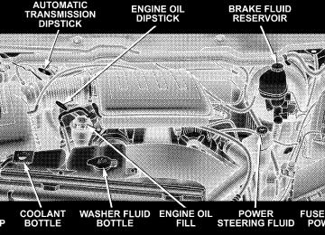
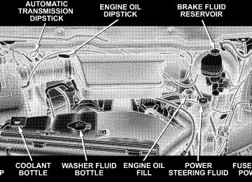
ENGINE COMPARTMENT— 3.7L
ENGINE COMPARTMENT— 4.7L
MAINTAINING YOUR VEHICLE 445
446 MAINTAINING YOUR VEHICLE
ENGINE COMPARTMENT— 5.7L
ONBOARD DIAGNOSTIC SYSTEM (OBD II) Your vehicle is equipped with a sophisticated onboard diagnostic system called OBDII. This system monitors the performance of the emissions, engine, and automatic transmission control systems. When these systems are operating properly, your vehicle will provide excellent performance and fuel economy, as well as engine emis- sions well within current government regulations. If any of these systems require service, the OBD II system will turn on the Malfunction Indicator Light (MIL). It will also store diagnostic codes and other information to assist your service technician in making repairs. Al- though your vehicle will usually be drivable and not need towing, see your authorized dealer for service as soon as possible.
MAINTAINING YOUR VEHICLE 447
CAUTION!
Prolonged driving with the Malfunction Indicator Light (MIL) on could cause further damage to the emission control system. It could also affect fuel economy and drivability. The vehicle must be ser- viced before any emissions tests can be performed. If the Malfunction Indicator Light (MIL) is flashing, severe catalytic converter damage and power loss will soon occur. Immediate service is required.
Loose Fuel Filler Cap Message
If the vehicle’s diagnostic system determines that the fuel filler cap in loose, improperly installed, or damaged, a GASCAP message will be displayed in the instrument cluster. Tighten the gas cap until a “clicking” sound is heard. This is an indication that the gas cap is properly
448 MAINTAINING YOUR VEHICLE
tightened. Press the odometer reset button to turn the message off. If the problem persists, the message will appear the next time the vehicle is started. This might indicate a damaged cap. If the problem is detected twice in a row, turn on the Malfunction Indicator Light (MIL). Resolving the problem will turn the MIL light off.
the system will
EMISSIONS INSPECTION AND MAINTENANCE PROGRAMS In some localities, it may be a legal requirement to pass an inspection of your vehicle’s emissions control system. Failure to pass could prevent vehicle registration.
For states which have an Inspection and Mainte- nance (I/M) requirement, this check verifies the following: the Malfunction Indicator Lamp (MIL) is functioning and is not on when the engine is running, and that the On Board Diagnostic (OBD) system is ready for testing.
Normally, the OBD system will be ready. The OBD system may not be ready if your vehicle was recently serviced, if you recently had a dead battery, or a battery replacement. If the OBD system should be determined not ready for the I/M test, your vehicle may fail the test. Your vehicle has a simple ignition key actuated test which you can use prior to going to the test station. To check if your vehicle’s OBD system is ready, you must do the following: 1. Insert your ignition key into the ignition switch. 2. Turn the ignition to the ON position, but do not crank or start the engine. 3. If you crank or start the engine, you will have to start this test over. 4. As soon as you turn your key to the ON position, you will see your MIL symbol come on as part of a normal bulb check.
MAINTAINING YOUR VEHICLE 449
Regardless of whether your vehicle’s OBD system is ready or not ready, if the MIL symbol is illuminated during normal vehicle operation, you should have your vehicle serviced before going to the I/M station. The I/M station can fail your vehicle because the MIL symbol is on with the engine running.
REPLACEMENT PARTS Use of genuine Mopart parts for normal/scheduled maintenance and repairs is highly recommended to en- sure the designed performance. Damage or failures caused by the use of non-Mopart parts for maintenance and repairs will not be covered by the manufacturer’s warranty.
5. Approximately 15 seconds later, one of two things will happen:
a. The MIL will blink for approximately five seconds and then remain on until the first engine crank or the key is turned off. This means that your vehicle’s OBD system is not ready and you should not proceed to the I/M station. b. The MIL will remain fully illuminated until the first engine crank or the key is turned off. This means that your vehicle’s OBD system is ready and you can proceed to the I/M station.
If your OBD system is not ready, you should see your authorized dealer or repair facility. If your vehicle was recently serviced, or had a battery failure or replacement, you may need to do nothing more than drive your vehicle as you normally would in order for your OBD system to update. A recheck with the above test routine may then indicate that the system is now ready.
450 MAINTAINING YOUR VEHICLE
AUTHORIZED DEALER SERVICE Your authorized dealer has the qualified service person- nel, special tools and equipment to perform all service operations in an expert manner. Service manuals are available which include detailed service information for your vehicle. Refer to these manuals before attempting any procedure yourself. NOTE: systems can result against you.
Intentional tampering with emissions control in civil penalties being assessed
WARNING!
You can be badly injured working on or around a motor vehicle. Do only that service work for which you have the knowledge and the proper equipment. If you have any doubt about your ability to perform a service job, take your vehicle to a competent mechanic.
MAINTENANCE PROCEDURES The pages that follow contain the required maintenance services determined by the engineers who designed your vehicle. Besides the maintenance items for which there are fixed maintenance intervals, there are other items that should operate satisfactorily without periodic maintenance. However, if a malfunction of these items does occur, it could adversely affect the engine or vehicle performance. These items should be inspected if a malfunction is observed or suspected.
Engine Oil
Checking Oil Level To assure proper lubrication of your vehicle’s engine, the engine oil must be maintained at the correct level. The best time to check the engine oil level is about five minutes after a fully warmed up engine is shut off or before starting the engine after it has sat overnight. Checking the oil while the vehicle is on level ground will improve the accuracy of the oil level readings. Always maintain the oil level within the SAFE zone on the dipstick. Adding one quart of oil when the reading is at the bottom of the SAFE zone will result in a reading at the top of the safe zone on these engines.
MAINTAINING YOUR VEHICLE 451
CAUTION!
Overfilling or underfilling the crankcase will cause oil aeration or loss of oil pressure. This could damage your engine.
452 MAINTAINING YOUR VEHICLE
Change Engine Oil Follow the Maintenance Schedule for recommended en- gine oil change intervals. Engine Oil Selection For best performance and maximum protection under all types of operating conditions, the manufacturer only recommends engine oils that are API-certified and meet the requirements of DaimlerChrysler Material Standard MS-6395.
American Petroleum Institute (API) Engine Oil Identification Symbol
This symbol means that the oil has been certified by the American Petroleum Institute (API). The manufacturer only recommends API-Certified engine oils.
Engine Oil Viscosity (SAE Grade) SAE 5W-20 engine oil is recommended for all operating temperatures. This engine oil improves low temperature starting and vehicle fuel economy. The engine oil filler cap also shows the recommended engine oil viscosity for your engine. For information on engine oil filler cap location, refer to the “Engine Compartment” illustration in this section.
NOTE: Vehicles equipped with a 5.7L engine must use SAE 5W-20 oil. Failure to do so may result in improper operation of the Multi-Displacement System (MDS). Re- fer to “Multi-Displacement System” under “Starting and Operating” in Section 5. NOTE: For 2500/3500 trucks with a 5.7L engine oper- ating under a gross combined weight rating of 14,000 lbs. or greater, SAE 5W-30 engine oil is recommended for all operating temperatures. Lubricants, which do not have both the engine oil certi- fication mark and the correct SAE viscosity grade num- ber, should not be used. Synthetic Engine Oils You may use synthetic engine oils if the recommended oil quality requirements are met, and the recommended maintenance intervals for oil and filter changes are followed.
MAINTAINING YOUR VEHICLE 453
Materials Added to Engine Oil The manufacturer strongly recommends against the ad- dition of any additives (other than leak detection dyes) to the engine oil. Engine oil is an engineered product and its performance may be impaired by supplemental addi- tives. Disposing of Used Engine Oil and Oil Filters Care should be taken in disposing of used engine oil and oil filters from your vehicle. Used oil and oil filters, indiscriminately discarded, can present a problem to the environment. Contact your authorized dealer, service station, or governmental agency for advice on how and where used oil and oil filters can be safely discarded in your area.
454 MAINTAINING YOUR VEHICLE
Engine Oil Filter The engine oil filter should be replaced at every engine oil change. Engine Oil Filter Selection The manufacturer’s engines have a full-flow type oil filter. Use a filter of this type for replacement. The quality of replacement filters varies considerably. Only high- quality filters should be used to assure most efficient service. Mopar Engine Oil Filters are a high-quality oil filter and are recommended. Drive Belts — Check Condition and Tension Belt tension is controlled by means of an automatic tensioner. No belt tension adjustments are required. However, belt and belt tensioner condition should be inspected at the specified intervals and replaced if re- quired. See your authorized dealer for service.
At the mileage indicated in the maintenance schedule, all belts and tensioner should be checked for condition. Improper belt tension can cause belt slippage and failure. Belts should be inspected for evidence of cuts, cracks, glazing or frayed cords and replaced if there is indication of damage which could result in belt failure. Low gen- erator belt tension can cause battery failure. Also check belt routing to make sure there is no interfer- ence between the belts and other engine components. Spark Plugs (Gas Engines) Spark plugs must fire properly to assure engine perfor- mance and emission control. New plugs should be in- stalled at the specified mileage. The entire set should be replaced if there is any malfunction due to a faulty spark plug. Malfunctioning spark plugs can damage the cata- lytic converter. For proper type of replacement spark plugs, refer to the “Spark Plugs” under “Fluids, Lubri- cants and Genuine Parts” in Section 7.
Engine Air Cleaner Filter Follow the Maintenance Schedule for recommended En- gine Air Cleaner Filter change intervals.
WARNING!
The air induction system (air cleaner, hoses, etc.) can provide a measure of protection in the case of engine backfire. Do not remove the air induction system (air cleaner, hoses, etc.) unless such removal is necessary for repair or maintenance. Make sure that no one is near the engine compartment before starting the vehicle with the air induction system (air cleaner, hoses, etc.) removed. Failure to do so can result in serious personal injury.
MAINTAINING YOUR VEHICLE 455
Engine Fuel Filter A plugged fuel filter can cause stalling, limit the speed at which a vehicle can be driven or cause hard starting. Should an excessive amount of dirt accumulate in the fuel tank, frequent filter replacement may be necessary. Catalytic Converter The catalytic converter requires the use of unleaded fuel only. Leaded gasoline will destroy the effectiveness of the catalyst as an emission control device. Under normal operating conditions, the catalytic con- verter will not require maintenance. However, it is im- portant to keep the engine properly tuned to assure proper catalyst operation and prevent possible catalyst damage.
456 MAINTAINING YOUR VEHICLE
CAUTION!
WARNING!
Damage to the catalytic converter can result if your vehicle is not kept in proper operating condition. In the event of engine malfunction, particularly involv- ing engine misfire or other apparent loss of perfor- mance, have your vehicle serviced promptly. Contin- ued operation of your vehicle with a severe malfunction could cause the converter to overheat, resulting in possible damage to the converter and the vehicle.
NOTE: systems can result against you.
Intentional tampering with emissions control in civil penalties being assessed
A hot exhaust system can start a fire if you park over materials that can burn. Such materials might be grass or leaves coming into contact with your exhaust system. Do not park or operate your vehicle in areas where your exhaust system can contact anything that can burn.
In unusual situations involving grossly malfunctioning engine operation, a scorching odor may indicate severe and abnormal catalyst overheating. If this occurs, the vehicle should be stopped, the engine shut off and the vehicle allowed to cool. Thereafter, service, including a tune-up to manufacturer’s specifications, should be ob- tained immediately.
To minimize the possibility of catalyst damage: † Do not shut off the engine or interrupt the ignition when the transmission is in gear and the vehicle is in motion. † Do not try to start the engine by pushing or towing the † Do not idle the engine with any spark plug wires disconnected or removed, such as when diagnostic testing, or for prolonged periods during very rough idling or malfunctioning operating conditions.
vehicle.
MAINTAINING YOUR VEHICLE 457
Emission-Related Components
the intervals specified.
Positive Crankcase Valve (PCV) Proper operation of the crankcase ventilation system requires that the PCV valve be free of sticking or plug- ging from deposits. Deposits can accumulate in the PCV valve and passages with increasing mileage. Have the PCV valve, hoses, and passages checked for proper operation at the valve is plugged or sticking, replace with a new valve— do not attempt to clean the old PCV valve! Check the ventila- tion hoses for indications of damage, weepage or plug- ging with deposits. Replace if necessary. Maintenance-Free Battery The top of the maintenance-free battery is permanently sealed. You will never have to add water, nor is periodic maintenance required.
If
458 MAINTAINING YOUR VEHICLE
WARNING!
† Battery fluid is a corrosive acid solution and can burn or even blind you. Don’t allow battery fluid to contact your eyes, skin or clothing. Don’t lean over a battery when attaching clamps. If acid splashes in eyes or on skin, flush the area imme- diately with large amounts of water. † Battery gas is flammable and explosive. Keep flame or sparks away from the battery. Don’t use a booster battery or any other booster source with an output greater than 12 volts. Don’t allow cable clamps to touch each other. † Battery posts, terminals and related accessories contain lead and lead compounds. Wash hands after handling.
CAUTION!
† It is essential when replacing the cables on the battery that the positive cable is attached to the positive post and the negative cable is attached to the negative post. Battery posts are marked (+) positive and (-) negative and identified on the battery case. † If a “fast charger” is used while the battery is in the vehicle, disconnect both vehicle battery cables before connecting the charger to the battery. Do not use a “fast charger” to provide starting voltage.
Air Conditioner Maintenance For best possible performance, your air conditioner should be checked and serviced by an Authorized Dealer at the start of each warm season. This service should include cleaning of the condenser fins and a performance test. Drive belt tension should also be checked at this time. NOTE: Refer to Section 3 of the Warranty Information book for further warranty information.
MAINTAINING YOUR VEHICLE 459
WARNING!
† Use only refrigerants and compressor lubricants approved by the manufacturer for your air condi- tioning system. Some unapproved refrigerants are flammable and can explode, injuring you. Other unapproved refrigerants or lubricants can cause the system to fail, requiring costly repairs. † The air conditioning system contains refrigerant under high pressure. To avoid risk of personal injury or damage to the system, adding refrigerant or any repair requiring lines to be disconnected should be done by an experienced repairman.
NOTE: Use only manufacturer approved A/C System Sealers, Stop Leak Products, Seal Conditioners, Compres- sor Oil, or Refrigerants.
460 MAINTAINING YOUR VEHICLE
Refrigerant Recovery and Recycling R-134a Air Conditioning Refrigerant is a hydrofluoro- carbon (HFC) that is endorsed by the Environmental Protection Agency (EPA) and is an ozone-saving product. However, the manufacturer recommends that air condi- tioning service be performed by authorized dealers or other service facilities using recovery and recycling equipment. Power Steering — Fluid Check Checking the power steering fluid level at a defined service interval is not required. The fluid should only be checked if a leak is suspected, abnormal noises are apparent, and/or the system is not functioning as antici- pated. Coordinate inspection efforts through an autho- rized dealer.
WARNING!
Fluid level should be checked on a level surface and with the engine off to prevent injury from moving parts and to ensure accurate fluid level reading. Do not overfill. Use only manufacturers recommended power steering fluid.
If necessary, add fluid to restore to the proper indicated level. With a clean cloth, wipe any spilled fluid from all surfaces. Refer to “Fluids, Lubricants, and Genuine Parts” in this section for correct fluid type. Front Suspension Ball Joints
4 x 2 Models The ball joints and seals should be inspected whenever the vehicle is serviced for other reasons.
if the seals on the ball
The ball joints originally supplied with the vehicle are permanently lubricated at the factory and do not require service. However, joints are the joints should be replaced. Serviceable damaged, replacement ball joints are available. Front suspension ball joints should be replaced only by a qualified service technician using tools specially de- signed for this purpose. Damage to the joints and/or suspension components may result if improper replace- ment procedures are used. If seals are damaged the ball joints should be replaced to prevent leakage or contamination of the grease. Steering Linkage — Inspection Whenever the vehicle is hoisted, all steering linkage joints should be inspected for evidence of damage. If seals are damaged, parts should be replaced to prevent
MAINTAINING YOUR VEHICLE 461
leakage or contamination of the grease. Lubricate the steering linkage regularly according to the “Maintenance Schedule” in this manual. Half-shaft Constant Velocity Joints All four-wheel drive 1500 models are equipped with four constant velocity joints. Periodic lubrication of these joints is not required. However, the joint boots should be inspected for external leakage or damage, periodically. If external leakage or damage is evident, the joint boot and grease should be replaced immediately. Continued op- eration could result in failure of the joint due to water and dirt contamination of the grease. This would require complete replacement of the joint assembly. Refer to the Service Manual for the detailed replacement procedure.
462 MAINTAINING YOUR VEHICLE
Front Prop Shaft Lubrication — 2500/3500 (4X4) Models Lubricate the front driveshaft grease fitting at each oil change listed in the appropriate Maintenance Schedule for your vehicle. Use Mopart type MS-6560 (lithium- based grease), or equivalent.
Front Driveshaft Grease Fitting
Body Lubrication
Locks and all body pivot points, including such items as seat tracks, doors, liftgate, tailgate, sliding doors and hood hinges, should be lubricated periodically to assure quiet, easy operation and to protect against rust and wear. Prior to the application of any lubricant, the parts concerned should be wiped clean to remove dust and grit. After lubricating, excess oil and grease should be removed. Particular attention should also be given to hood latching components to ensure proper function. When performing other underhood services, the hood latch, release mechanism and safety catch should be cleaned and lubricated. The external lock cylinders should be lubricated twice a year, preferably in the Fall and Spring. Apply a small amount of a high-quality lubricant such as Mopart Lock Cylinder Lubricant di- rectly into the lock cylinder.
Windshield Wiper Blades The rubber edges of the wiper blades and the windshield should be cleaned periodically with a sponge or soft cloth and a mild nonabrasive cleaner. This will remove accu- mulations of salt or road film. Operation of the wipers on dry glass for long periods may cause deterioration of the wiper blades. Always use washer fluid when using the wipers to remove salt or dirt from a dry windshield. Avoid using the wiper blades to remove frost or ice from the windshield. Keep the blade rubber out of contact with petroleum products such as engine oil, gasoline, etc. Windshield Washers The fluid reservoir is located under the hood and should be checked for fluid level at regular intervals. Fill the
MAINTAINING YOUR VEHICLE 463
reservoir with windshield washer solvent only (not ra- diator antifreeze). When refilling the washer fluid reser- voir, take some washer fluid and apply it to a cloth or towel and wipe clean the wiper blades, this will help blade performance. To prevent freeze-up of your windshield washer system in cold weather, select a solution or mixture that meets or exceeds the temperature range of your climate. This rating information can be found on most washer fluid containers. The washer fluid reservoir will hold a full gallon of fluid when the Low Washer Fluid Light illuminates.
464 MAINTAINING YOUR VEHICLE
WARNING!
Commercially available windshield washer solvents are flammable. They could ignite and burn you. Care must be exercised when filling or working around the washer solution.
After the engine has warmed, operate the defroster for a few minutes to reduce the possibility of smearing or freezing the fluid on the cold windshield. Mopart All Weather Windshield Washer Solution, used with water as directed on the container, aids cleaning action, reduces the freezing point to avoid line clogging, and is not harmful to paint or trim.
Exhaust System The best protection against carbon monoxide entry into the vehicle body is a properly maintained engine exhaust system. Whenever a change is noticed in the sound of the exhaust system, when exhaust fumes can be detected inside the vehicle, or when the underside or rear of the vehicle is damaged, have a competent mechanic inspect the com- plete exhaust system and adjacent body areas for broken, damaged, deteriorated, or mispositioned parts. Open seams or loose connections could permit exhaust fumes to seep into the passenger compartment. In addition, inspect the exhaust system each time the vehicle is raised for lubrication or oil change. Replace as required.
WARNING!
Cooling System
MAINTAINING YOUR VEHICLE 465
Exhaust gases can injure or kill. They contain carbon monoxide (CO) which is colorless and odorless. Breathing it can make you unconscious and can eventually poison you. To avoid breathing CO, refer to Exhaust Gas in the Safety Tips section of this manual.
Exhaust System Rubber Isolator and Loop-Type Hanger — If Equipped Inspect surfaces whenever the vehicle is hoisted for rubber to metal separation or deep cracks. SLIGHT CRACKING DUE TO WEATHERING DOES NOT AD- VERSELY AFFECT PERFORMANCE. If, however, exces- sively deep localized cracks are present, or any part of the exhaust system abnormally contacts the underbody hard- ware, the isolator and/or hanger should be replaced.
WARNING!
You or others can be badly burned by hot coolant or steam from your radiator. If you see or hear steam coming from under the hood, don’t open the hood until the radiator has had time to cool. Never try to open a cooling system pressure cap when the radiator is hot.
Engine Coolant Checks Check the engine coolant (antifreeze) protection every 12
months (before the onset of freezing weather, where applicable). If coolant is dirty or rusty in appearance, the system should be drained, flushed and refilled with fresh coolant. Check the front of the A/C condenser for any466 MAINTAINING YOUR VEHICLE
accumulation of bugs, leaves, etc. If dirty, clean by gently spraying water from a garden hose vertically down the face of the condenser. Check the coolant recovery bottle tubing for brittle rub- ber, cracking, tears, cuts and tightness of the connection at the bottle and radiator. Inspect the entire system for leaks. With the engine at normal operating temperature (but not running), check the cooling system pressure cap for proper vacuum sealing by draining a small amount of coolant from the radiator drain cock. If the cap is sealing properly, the engine coolant (antifreeze) will begin to drain from the coolant recovery bottle. DO NOT RE- MOVE THE COOLANT PRESSURE CAP WHEN THE COOLING SYSTEM IS HOT.
Cooling System — Drain, Flush and Refill At the intervals shown on the Maintenance Schedules, the system should be drained, flushed and refilled. If the solution is dirty or contains a considerable amount of sediment, clean and flush with a reliable cooling system cleaner. Follow with a thorough rinsing to remove all deposits and chemicals. Properly dispose of old antifreeze solution. Selection Of Coolant Use only the manufacturer’s recommended coolant; for correct coolant type, refer to “Engine Coolant” under “Fluids, Lubricants and Genuine Parts” in this section.
CAUTION!
† Mixing of coolants other than specified HOAT engine coolants, may result in engine damage and may decrease corrosion protection. If a non-HOAT coolant is introduced into the cooling system in an emergency, it should be replaced with the speci- fied coolant as soon as possible. † Do not use plain water alone or alcohol-base engine coolant (antifreeze) products. Do not use additional rust inhibitors or antirust products, as they may not be compatible with the radiator engine coolant and may plug the radiator. † This vehicle has not been designed for use with Propylene Glycol based coolants. Use of Propy- lene Glycol based coolants is not recommended.
MAINTAINING YOUR VEHICLE 467
Adding Coolant Your vehicle has been built with an improved engine coolant that allows extended maintenance intervals. This coolant can be used up to 5 Years or 100,000 miles (160
000 km) before replacement. To prevent reducing this extended maintenance period, it is important that you use the same coolant throughout the life of your vehicle. Please review these recommendations for using Hybrid Organic Additive Technology (HOAT) coolant. When adding coolant: † The manufacturerrecommends using Mopart Antifreeze/Coolant 5 Year/100,000 Mile Formula HOAT (Hybrid Organic Additive Technology). † Mix a minimum solution of 50% HOAT engine coolant and distilled water. Use higher concentrations (not to exceed 70%) if temperatures below -34°F (-37°C) are anticipated.
468 MAINTAINING YOUR VEHICLE
† Use only high purity water such as distilled or deion- ized water when mixing the water/engine coolant solution. The use of lower quality water will reduce the amount of corrosion protection in the engine cooling system.
Please note that it is the owner’s responsibility to main- tain the proper level of protection against freezing ac- cording to the temperatures occurring in the area where the vehicle is operated. NOTE: Mixing coolant types will decrease the life of the engine coolant and will require more frequent coolant changes. Cooling System Pressure Cap The cap must be fully tightened to prevent loss of coolant, and to ensure that coolant will return to the radiator from the coolant recovery bottle.
The cap should be inspected and cleaned if there is any accumulation of foreign material on the sealing surfaces.
WARNING!
† The warning words “DO NOT OPEN HOT” on the cooling system pressure cap are a safety pre- caution. Never add coolant when the engine is overheated. Do not loosen or remove the cap to cool an overheated engine. Heat causes pressure to build up in the cooling system. To prevent scald- ing or injury, do not remove the pressure cap while the system is hot or under pressure. † Do not use a pressure cap other than the one specified for your vehicle. Personal injury or en- gine damage may result.
Disposal of Used Engine Coolant Used ethylene glycol-based engine coolant is a regulated substance requiring proper disposal. Check with your local authorities to determine the disposal rules for your community. To prevent ingestion by animals or children do not store ethylene glycol-based engine coolant in open containers or allow it to remain in puddles on the ground. If ingested by a child, contact a physician immediately. Clean up any ground spills immediately. Coolant Level The coolant bottle provides a quick visual method for determining that the coolant level is adequate. With the engine cold, the level of the coolant in the coolant recovery bottle should be between the ranges indicated on the bottle. The radiator normally remains completely full, so there is no need to remove the radiator cap unless checking for coolant freeze point or replacing coolant. Advise your
MAINTAINING YOUR VEHICLE 469
service attendant of this. As long as the engine operating temperature is satisfactory, the coolant bottle need only be checked once a month. When additional coolant is needed to maintain the proper level, it should be added to the coolant bottle. Do not overfill. Points To Remember NOTE: When the vehicle is stopped after a few miles (a few kilometers) of operation, you may observe vapor coming from the front of the engine compartment. This is normally a result of moisture from rain, snow, or high humidity accumulating on the radiator and being vapor- ized when the thermostat opens, allowing hot coolant to enter the radiator. If an examination of your engine compartment shows no evidence of radiator or hose leaks, the vehicle may be safely driven. The vapor will soon dissipate.
470 MAINTAINING YOUR VEHICLE
† Do not overfill the coolant recovery bottle. † Check coolant freeze point in the radiator and in the coolant recovery bottle. If antifreeze needs to be added, contents of coolant recovery bottle must also be protected against freezing. † If frequent coolant additions are required, or if the level in the coolant recovery bottle does not drop when the engine cools, the cooling system should be pres- sure tested for leaks. † Maintain coolant concentration at 50% HOAT engine coolant (minimum) and distilled water for proper corrosion protection of your engine, which contains aluminum components. † Make sure that the radiator and coolant recovery bottle overflow hoses are not kinked or obstructed.
† Keep the front of the radiator clean. If your vehicle is equipped with air conditioning, keep the front of the condenser clean, also. † Do not change the thermostat for Summer or Winter operation. If replacement is ever necessary, install ONLY the correct type thermostat. Other designs may result in unsatisfactory coolant performance, poor gas mileage, and increased emissions.
Hoses And Vacuum/Vapor Harnesses Inspect surfaces of hoses and nylon tubing for evidence of heat and mechanical damage. Hard or soft spots, brittle rubber, cracking, tears, cuts, abrasions, and exces- sive swelling indicate deterioration of the rubber. Pay particular attention to those hoses nearest to high heat sources such as the exhaust manifold. Inspect hose routing to be sure hoses do not come in contact with any heat source or moving component which may cause heat damage or mechanical wear.
Ensure nylon tubing in these areas has not melted or collapsed. Inspect all hose connections such as clamps and cou- plings to make sure they are secure and no leaks are present. Components should be replaced immediately if there is any evidence of wear or damage that could cause failure. Fuel System Connections Electronic Fuel Injection high pressure fuel systems are designed with tubes and special connects, connections and clamps which have unique material characteristics to provide adequate sealing and resist attack by deterio- rated gasoline. You are urged to use only the manufacture’s specified tubes, connections and clamps, or their equivalent in material and specification, in any fuel system servicing.
MAINTAINING YOUR VEHICLE 471
Brake System
Power Disc Brakes (Front and Rear) Disc brakes do not require adjustment; however, several hard stops during the break-in period are recommended to seat the linings and wear off any foreign material. Brake and Power Steering Hoses When the vehicle is serviced for scheduled maintenance, inspect surface of hoses and nylon tubing for evidence of heat and mechanical damage. Hard and brittle rubber, cracking, tears, cuts, abrasion, and excessive swelling indicate deterioration of the rubber. Particular attention should be made to examining those hose surfaces nearest to high heat sources, such as the exhaust manifold. Ensure nylon tubing in these areas has not melted or collapsed.
472 MAINTAINING YOUR VEHICLE
Inspect all hose connections such as clamps and cou- plings to make sure they are secure and no leaks are present. NOTE: Often, fluid such as oil, power steering fluid, and brake fluid are used during assembly plant opera- tions to facilitate the assembly of hoses to couplings. Therefore, oil wetness at the hose-coupling area is not necessarily an indication of leakage. Actual dripping of hot fluid when systems are under pressure (during vehicle operation), should be noted before hose is re- placed based on leakage. Inspection of brake hoses should be performed NOTE: whenever the brake system is serviced and every engine oil change. Inspect hydraulic brake hoses for surface cracking, scuffing, or worn spots. If there is any evidence of cracking, scuffing, or worn spots, the hose should be replaced immediately! Eventual deterioration of the hose can take place resulting in a possibility of a burst failure.
WARNING!
Worn brake hoses can burst and cause brake failure. You could have an accident. If you see any signs of cracking, scuffing, or worn spots, have the brake hoses replaced immediately.
Brake Master Cylinder — Brake Fluid Level Check The fluid level of the master cylinder should be checked when performing under the hood service, or immedi- ately if the brake system warning lamp indicates system failure. The brake master cylinder has a translucent plastic reservoir. On the outboard side of the reservoir, there is a “MAX” dot and an “MIN” dot. The fluid level must be kept within these two dots. Do not add fluid above the MAX mark, because leakage may occur at the cap.
With disc brakes the fluid level can be expected to fall as the brake linings wear. However, an unexpected drop in fluid level may be caused by a leak and a system check should be conducted. For correct fluid type, refer to ”Brake Master Cylinder” under “Fluids, Lubricants and Genuine Parts” in this section.
WARNING!
Use of a brake fluid that may have a lower initial boiling point, or is unidentified as to specification, may result in sudden brake failure during hard prolonged braking. You could have an accident.
MAINTAINING YOUR VEHICLE 473
WARNING!
Overfilling the brake fluid reservoir can result in spilling brake fluid on hot engine parts and the brake fluid catching fire.
Use only brake fluid that has been in a tightly-closed container to avoid contamination from foreign matter or moisture.
CAUTION!
Do not allow a petroleum-base fluid to contaminate the brake fluid. Seal damage may result.
474 MAINTAINING YOUR VEHICLE
Clutch Hydraulic System
The clutch hydraulic system is a sealed maintenance-free system. In the event of leakage or other malfunction, the system must be replaced. Clutch Linkage If the clutch pedal linkage begins to squeak or grunt, the clutch pedal pivot bushings should be lubricated. For the correct lubricant type, refer to “Fluids, Lubricants and Genuine Parts” in this Section. Rear Axle And 4x4 Front Driving Axle Fluid Level For the correct Fluid type, refer to “Fluids, Lubricants and Genuine Parts” in this Section. For normal service, periodic fluid level checks are not required. When the vehicle is serviced for other reasons the exterior surfaces of the axle assembly should be inspected. If gear oil leakage is suspected inspect the fluid level.
This inspection should be made with the vehicle in a level position. The fluid level should be even with the bottom of the fill hole for the Manufacturer’s C205F HD front axles. The fluid level should be 5/8 in (16 mm) below the fill hole on 9 1/4 in manufacturer’s rear axles. For all 2500/3500 Model axles, the fluid level should be 1/4” ± 1/4 in(6.4 mm ± 6.4 mm) below the fill hole on the 9.25 in front and 3/4 in ± 1/4 in (19 mm ± 6.4 mm) on 10.5 in rear axles. The 11.5 in rear axle level should be 1/4
in ± 1/4 in (6.4 mm ± 6.4 mm) below the fill hole. Drain and Refill Follow the Maintenance Schedule for recommended front and rear axle fluid change intervals. Lubricant Selection For the correct fluid type, refer to “Fluids, Lubricants and Genuine Parts” in this Section.NOTE: The presence of water in the gear lubricant will result in corrosion and possible failure of differential components. Operation of the vehicle in water, as may be encountered in some off-highway types of service, will require draining and refilling the axle to avoid damage. Limited-Slip Differentials in 1500 Model vehicles re- quire that 4 oz. (118 ml) Mopart limited slip additive be added to the gear lubricant. Refer to Fluids, Lubricants and Genuine Parts for correct fluid type. The Mopart Limited Slip Additive should be added to the gear lubricant whenever a fluid change is made. 2500/3500 Model Axles DO NOT REQUIRE any limited slip oil additive (friction modifiers).
MAINTAINING YOUR VEHICLE 475
Transfer Case
Drain And Refill Follow the Maintenance Schedule for recommended transfer case fluid change intervals. Lubricant Selection For the correct Fluid type, refer to “Fluids, Lubricants and Genuine Parts” in this Section. Fluid Level Check This fluid level can be checked by removing the filler plug. The fluid level should be to the bottom edge of the filler plug hole with the vehicle in a level position.
476 MAINTAINING YOUR VEHICLE
Manual Transmission
Lubricant Selection G238 (6-Speed Manual Transmission — If Equipped) This transmission is filled with manual transmission fluid at the factory. This fluid does not require periodic changing. If it is necessary to add or change fluid in this transmission refer to Fluids, Lubricants and Genuine Parts for correct fluid type. This is the only lubricant recommended for use in the Getrag 238 transmission. Lubricant Selection G56 (6-Speed Manual Transmission — If Equipped) Follow the Maintenance Schedule for recommended transmission fluid change intervals. If it is necessary to add or change fluid in this transmission refer to “Fluids, Lubricants and Genuine Parts” for correct fluid type. This is the only lubricant recommended for use in the G56
transmission.Fluid Level Check – All Manual Transmissions This fluid level can be checked by removing the fill plug. If the level of the lubricant is more than 1/4 in(6.4 mm) below the bottom of the filler hole while the vehicle is on level ground, enough lubricant should be added to bring the level to the bottom of the filler hole. Automatic Transmission
Selection Of Lubricant It is important that the proper lubricant is used in the transmission to assure optimum transmission perfor- mance. Use only manufacturer’s recommended transmis- sion fluid; refer to “Fluids, Lubricants and Genuine Parts” in this section for correct fluid type. It is important that the transmission fluid be maintained at the pre- scribed level using the recommended fluid.
CAUTION!
Using a transmission fluid other than the manufac- turer’s recommended fluid may cause deterioration in transmission shift quality and/or torque converter shudder. Using a transmission fluid other than the manufacturer’s recommended fluid will result in more frequent fluid and filter changes. Refer to “Fluids, Lubricants and Genuine Parts” in this sec- tion for correct fluid type.
Fluid Level Check If equipped with a dipstick, use the following procedure. If your vehicle has a capped dipstick tube, it is sealed and should not be tampered with. Your authorized dealer has the proper tools to ensure that the fluid level is set properly. The fluid level should be checked when the
MAINTAINING YOUR VEHICLE 477
engine is fully warmed up and the fluid in the transmis- sion is at normal operating temperature. Operation of the transmission with an improper fluid level will greatly reduce the life of the transmission and of the fluid. Check the fluid level whenever the vehicle is serviced. Fluid Level Check – 545RFE/42RLE Check the fluid level while the transmission is at normal operating temperature 82°C (180°F). This occurs after at least 15 mi (25 km) of driving. At normal operating temperature the fluid cannot be held comfortably be- tween the fingertips. To check the automatic transmission fluid level properly, the following procedure must be used: 1. Operate the engine at idle speed and normal operating temperature. 2. The vehicle must be on level ground.
478 MAINTAINING YOUR VEHICLE
3. Fully apply the parking brake and press the brake pedal. 4. Place the gear selector momentarily in each gear position ending with the lever in PARK. 5. Remove the dipstick, wipe it clean and reinsert it until seated. 6. Remove the dipstick again and note the fluid level on both sides. The fluid level should be between the “HOT” (upper) reference holes on the dipstick at normal operat- ing temperature. Verify that solid coating of oil is seen on both sides of the dipstick. If the fluid is low, add as required into the dipstick tube. Do not overfill. After adding any quantity of oil through the oil fill tube, wait a minimum of two minutes for the oil to fully drain into the transmission before rechecking the fluid level.
If it is necessary to check the transmission below NOTE: the operating temperature, the fluid level should be between the two “COLD” (lower) holes on the dipstick with the fluid at approximately 70°F (21°C) (room tem- perature). If the fluid level is correctly established at room temperature, it should be between the “HOT” (upper) reference holes when the transmission reaches 180°F (82°C). Remember it is best to check the level at the normal operating temperature.
CAUTION!
Be aware that if the fluid temperature is below 50°F (10°C) it may not register on the dipstick. Do not add fluid until the temperature is elevated enough to produce an accurate reading.
7. Check for leaks. Release parking brake. To prevent dirt and water from entering the transmission after checking or replenishing fluid, make certain that the dipstick cap is properly reseated. It is normal for the dipstick cap to spring back slightly from its fully seated position, as long as its seal remains engaged in the dipstick tube. Automatic Transmission Fluid and Filter Change Follow the Maintenance Schedule for recommended transmission fluid and filter change intervals. NOTE: reason, the fluid and filter(s) should be changed. It is important that proper lubricant is used in the transmission. For the correct Fluid type, refer to “Fluids, Lubricants and Genuine Parts” in this Section.
If the transmission is disassembled for any
MAINTAINING YOUR VEHICLE 479
Special Additives Automatic Transmission Fluid (ATF) is an engineered product and its performance may be impaired by supple- mental additives. Therefore, do not add any fluid addi- tives to the transmission. The only exception to this policy is the use of special dyes to aid in detecting fluid leaks. In addition, avoid using transmission sealers as they may adversely affect seals. Front and Rear Wheel Bearings
Front Wheel Bearings Front wheel bearings for all vehicles are sealed-for-life. They do not require greasing or seal replacement. In some instances, these bearings will “purge” excess grease and the bearing will look slightly wet. This is normal. Periodic inspection for excess play is recommended.
can be identified by the Noise Emission Control Label located in the operator’s compartment.
480 MAINTAINING YOUR VEHICLE
Rear Wheel Bearings — Manufacturer’s Axles These bearings are normally considered permanently lubricated. Cleaning and repacking is required only when axle shafts are removed or in case of extreme water or dust contamination. Noise Control System Required Maintenance & Warranty For 3500 2-Wheel Drive and 4-Wheel Drive models over 10,000 lbs. (4 535 kg) Gross Vehicle Weight Rating. All vehicles built over 10,000 lbs (4 535 kg) Gross Vehicle Weight Rating and manufactured for sale and use in the United States are required to comply with the Federal Government’s Exterior Noise Regulations. These vehicles
In addition,
Required Maintenance for Noise Control Systems The following maintenance services must be performed every six months or 6,000 mi (9 600 km), whichever comes first, to assure proper operation of the noise control systems. inspection and service should be performed anytime a malfunction is observed or suspected. Proper maintenance of the entire vehicle will help the effectiveness of the noise control systems. Air Cleaner Assembly Inspect air cleaner housing for proper assembly and fit. Make certain that the air cleaner is properly positioned and the cover is tight. Check all hoses leading to the cleaner for tightness. The gasket between the air cleaner housing and throttle body must be intact and in good condition. The engine air cleaner filter must also be clean and serviced according to the instructions outlined in the appropriate maintenance schedule.
MAINTAINING YOUR VEHICLE 481
Tampering with Noise Control System Prohibited Federal law prohibits the following acts or the causing thereof: (1) the removal or rendering inoperative by any person, other than for purposes of maintenance, repair, or replacement, of any device or element of design incorpo- rated into any new vehicle for the purpose of noise control prior to its sale or delivery to the ultimate purchaser or while it is in use, or (2) the use of the vehicle after such device or element of design has been removed or rendered inoperative by any person. Among those acts presumed to constitute tampering are the acts listed below. AIR CLEANER † Removal of the air cleaner. † Inverting the air cleaner lid. † Removal of the air ducting.
482 MAINTAINING YOUR VEHICLE
EXHAUST SYSTEM † Removal or rendering inoperative exhaust system
components including the muffler or tailpipe.
ENGINE COOLING SYSTEM † Removal or rendering inoperative the fan clutch. † Removal of the fan shroud. Noise Emission Warranty The manufacturer warrants that this vehicle as manufac- tured by the manufacturer, was designed, built and equipped to conform at the time it left the manufacturer’s control with all applicable U.S. EPA Noise Control Regu- lations.
This warranty covers this vehicle as designed, built and equipped by the manufacturer, and is not limited to any particular part, component or system of the vehicle manufactured by the manufacturer. Defects in design, assembly or in any part, component or system of the vehicle as manufactured by the manufacturer, which, at the time it left the manufacturer’s control, caused noise emissions to exceed Federal standards, are covered by this warranty for the life of the vehicle.
MAINTAINING YOUR VEHICLE 483
Noise Systems Maintenance Chart and Service Log Insert Month, Day, Year under column mileage closest to the mileage at which service was performed. MILES KILOMETERS Exhaust system-inspect Air cleaner assembly-inspect ODOMETER READING PERFORMED BY PERFORMED AT
12,000
19 00018,000
29 00024,000
39 00030,000
48 00036,000
58 00042,000
68 00048,000
77 0006,000
10 00054,000
87 00060,000
97 00066,000
106 00072,000
116 00078,000
126 00084,000
135 00090,000
145 00096,000
154 000MILES KILOMETERS Exhaust system-inspect Air cleaner assembly-inspect ODOMETER READING PERFORMED BY PERFORMED AT
484 MAINTAINING YOUR VEHICLE
Appearance Care and Protection from Corrosion
Protection of Body and Paint from Corrosion Vehicle body care requirements vary according to geo- graphic locations and usage. Chemicals that make roads passable in snow and ice, and those that are sprayed on trees and road surfaces during other seasons, are highly corrosive to the metal in your vehicle. Outside parking, which exposes your vehicle to airborne contaminants, road surfaces on which the vehicle is operated, extreme hot or cold weather and other extreme conditions will have an adverse affect on paint, metal trim, and under- body protection. The following maintenance recommendations will enable you to obtain maximum benefit from the corrosion resistance built into your vehicle. What Causes Corrosion? Corrosion is the result of deterioration or removal of paint and protective coatings from your vehicle.
The most common causes are: † Road salt, dirt and moisture accumulation. † Stone and gravel impact. † Insects, tree sap and tar. † Salt in the air near seacoast localities. † Atmospheric fallout/industrial pollutants. Washing † Wash your vehicle regularly. Always wash your ve- hicle in the shade using Mopart Car Wash or a mild car wash soap, and rinse the panels completely with clear water. † If insects, tar or other similar deposits have accumu- lated on your vehicle, use Mopart Super Kleen Bug and Tar Remover to remove.
† Use Mopart Cleaner Wax to remove road film, stains and to protect your paint finish. Take care never to scratch the paint. † Avoid using abrasive compounds and power buffing that may diminish the gloss or thin out the paint finish.
CAUTION!
Do not use abrasive or strong cleaning materials such as steel wool or scouring powder, which will scratch metal and painted surfaces.
Special Care † If you drive on salted or dusty roads, or if you drive near the ocean, hose off the undercarriage at least once a month.
MAINTAINING YOUR VEHICLE 485
† It is important that the drain holes in the lower edges of the doors, rocker panels and trunk be kept clear and open. † If you detect any stone chips or scratches in the paint, touch them up immediately. The cost of such repairs is considered the responsibility of the owner. † If your vehicle is damaged due to an accident or similar cause which destroys the paint and protective coating, have your vehicle repaired as soon as pos- sible. The cost of such repairs is considered the respon- sibility of the owner. † If you carry special cargo such as chemicals, fertilizers, de-icer salt, etc., be sure that such materials are well packaged and sealed. † If a lot of driving is done on gravel roads, consider
mud or stone shields behind each wheel.
486 MAINTAINING YOUR VEHICLE
† Use Mopart touch up paint on scratches as soon as possible. Your authorized dealer has touch up paint to match the color of your vehicle.
Wheel and Wheel Trim Care All wheels and wheel trim, especially aluminum and chrome plated wheels should be cleaned regularly with a mild soap and water to prevent corrosion. To remove heavy soil and/or excessive brake dust, use Mopart Wheel Cleaner (05066247AB) or equivalent, or select a nonabrasive, non-acidic cleaner. Do not use scouring pads, steel wool, a bristle brush, or metal polishes. Only Mopart or equivalent is recommended. Do not use oven cleaner. Avoid automatic car washes that use acidic solutions or harsh brushes that may damage the wheels’ protective finish.
with a clean, dry towel.
YES Essentialst Fabric Cleaning Procedure – If equipped YES Essentialst seats may be cleaned in the following manner: † Remove as much of the stain as possible by blotting † Blot any remaining stain with a clean, damp towel. † For tough stains, apply Mopart Total Clean or a mild soap solution to a clean, damp cloth and remove stain. Use a fresh, damp towel to remove soap residue. † For grease stains, apply Mopart Multipurpose cleaner to a clean, damp cloth and remove stain. Use a fresh, damp towel to remove soap residue. † Do not use any solvents or protectants on Yes Essen-
tials products.
Interior Care Use Mopart Total Clean to clean fabric upholstery and carpeting. Use Mopart Total Clean to clean vinyl upholstery. Mopart Total Clean is specifically recommended for leather upholstery. Your leather upholstery can be best preserved by regular cleaning with a damp soft cloth. Small particles of dirt can act as an abrasive and damage the leather upholstery and should be removed promptly with a damp cloth. Stubborn soils can be removed easily with a soft cloth and Mopart Total Clean. Care should be taken to avoid soaking your leather upholstery with any liquid. Please do not use polishes, oils, cleaning fluids, solvents, deter- gents, or ammonia-based cleaners to clean your leather upholstery. Application of a leather conditioner is not required to maintain the original condition.
MAINTAINING YOUR VEHICLE 487
WARNING!
Do not use volatile solvents for cleaning purposes. Many are potentially flammable, and if used in closed areas they may cause respiratory harm.
Cleaning Headlights Your vehicle has plastic headlights that are lighter and less susceptible to stone breakage than glass headlights. Plastic is not as scratch resistant as glass and therefore different lens cleaning procedures must be followed. To minimize the possibility of scratching the lenses and reducing light output, avoid wiping with a dry cloth. To remove road dirt, wash with a mild soap solution fol- lowed by rinsing. Do not use abrasive cleaning components, solvents, steel wool or other aggressive material to clean the lenses.
488 MAINTAINING YOUR VEHICLE
Glass Surfaces All glass surfaces should be cleaned on a regular basis with Mopart Glass Cleaner or any commercial household-type glass cleaner. Never use an abrasive type cleaner. Use caution when cleaning the inside rear win- dow equipped with electric defrosters or the right rear quarter window equipped with the radio antenna. Do not use scrapers or other sharp instruments which may scratch the elements. When cleaning the rearview mirror, spray cleaner on the towel or rag that you are using. Do not spray cleaner directly on the mirror. Cleaning Plastic Instrument Cluster Lenses The lenses in front of the instruments in this vehicle are molded in clear plastic. When cleaning the lenses, care must be taken to avoid scratching the plastic.
1. Clean with a wet soft rag. A mild soap solution may be used, but do not use high alcohol content or abrasive cleaners. If soap is used, wipe clean with a clean damp rag. 2. Dry with a soft tissue. Seat Belt Maintenance Do not bleach, dye or clean the belts with chemical solvents or abrasive cleaners. This will weaken the fabric. Sun damage can also weaken the fabric. If the belts need cleaning, use a mild soap solution or lukewarm water. Do not remove the belts from the car to wash them. Replace the belts if they appear frayed or worn or if the buckles do not work properly. Dry with a soft tissue.
FUSES (INTEGRATED POWER MODULE) An integrated power module is located in the engine compartment near the battery. This center contains car- tridge fuses and mini fuses. A description of each fuse and component may be stamped on the inside cover, otherwise the cavity number of each fuse is stamped on the inside cover that corresponds to the following chart.
Integrated Power Module Location
Cavity Cartridge
Fuse
MAINTAINING YOUR VEHICLE 489
Mini Fuse 20 Amp Yellow 20 Amp Yellow
— 15 Amp Blue 20 Amp Yellow 10 Amp Red — 10 Amp Red
Description
Power Outlet Console
Cabin Compartment Node (CCN) Door Locks — Aisin Transmission Controls (Diesel Only) Power Sunroof
Vistronic Fan/ Wastegate Solenoid — Heated Mirrors
490 MAINTAINING YOUR VEHICLE
Cavity Cartridge
Fuse 30 Amp Pink
10
11
Mini Fuse
5 Amp Orange
20 Amp Yellow
Description
Off Road Module Power Trx-Off Rd Pkg Sen (Gas Engine Only) NOTE: Insert 5 amp fuse in this cavity to enable the TRX capa- bility (If Equipped). Ignition Off Draw (IOD)-Cabin Com- partment Node (CCN)/Radio/Under Hood Lamp/Wireless Control Module (WCM)/Satellite Digi- tal Audio Receiver (SDARS)/Hands Free Module (HFM)/EOM
12
13
14
15
16
17
1819
Cavity Cartridge
Fuse 30 Amp Pink
Mini Fuse
25 Amp Natural
15 Amp Blue 20 Amp Yellow 15 Amp Blue —
Description
Electric Brake
Power-Battery RWAL/ABS Module Feed Park Lights Left
Trailer Park Lights
Park Lights Right
— ABS Pump
Trailer Tow Battery Feed
40 Amp Green 30 Amp Pink
Cavity Cartridge
Fuse
20
21
22
23
24
25
26
20 Amp Blue
Mini Fuse 10 Amp Red 10 Amp Red 2 Amp Gray 10 Amp Red
10 Amp Red 20 Amp Yellow
Description
Occupant Restraints Controller (ORC) 2
Occupant Restraints/ Pass Disable Switch IGN Switch FeedHVAC
AISIN Relay Feed (Diesel Only) Power Mirror/T-Case Brake Brake Switch/Center High Mount Stop Light (CHMSL)/ Aftermarket CHMSL
Cavity Cartridge
Fuse 40 Amp Green
27
28
29
30
31
MAINTAINING YOUR VEHICLE 491
Mini Fuse
10 Amp Red
10 Amp Red 15 Amp Blue
10 Amp Red
Description
Power Seats
Power Run/Start- PCM/Steering Angle Sensor 4X4 Switch/Pass Dr Switch/EC Mirror Power Run/Start- ABS/RWAL/Smart Bar/YAW Sensor/ Universal Exhaust Gas Oxygen (Uego) Sensor Controller PCM (Gas)/TCM (Diesel 58RFE)
492 MAINTAINING YOUR VEHICLE
Cavity Cartridge
Fuse
32
33
34
3536
37
38
Mini Fuse 10 Amp Red
10 Amp Red — 15 Amp Blue
25 Amp Natural 15 Amp Blue
20 Amp Yellow
Description
Power Ignition Run — Adjustable Pedals LED Power-IGN Run — HVAC — Cabin Compartment Node (CCN) Illumi- nation Audio_Amplifier
Variable Gate Turbo (VGT) — Turbo Die- sel Power Outlet IP
Cavity Cartridge
Fuse
39
40
41
4230 Amp Pink
Mini Fuse 10 Amp Red
20 Amp Yellow
—
Description